


Highlights
What are the main findings?
- A lightweight computer vision algorithm using a depth camera and standard deviation metric can robustly identify flat zones for UAV landing in GPS-denied environments.
- The system performs reliable autonomous landings with minimal computational resources, fully integrated via a direct MAVLink connection.
What are the implications of the main findings?
- This work enables safe UAV landing without relying on GPS, external infrastructure, or heavy processing, making it ideal for low-cost drones.
- The approach supports real-time onboard deployment on constrained hardware, enhancing operational autonomy in unknown environments.
Abstract
This paper presents a safe landing methodology for Unmanned Aerial Vehicles (UAVs) when the GPS-based navigation system fails or is denied or unavailable. The approach relies on the estimation of a flat landing area when landing is required in an unknown area. The proposed system is based on a lightweight computer vision algorithm that enables real-time identification of suitable landing zones using a depth camera and an onboard companion computer. Analysis of small, spatially distributed areas to calculate the mean altitude and standard deviation across regions enables reliable selection of flat surfaces. A robust landing control algorithm is activated when the area meets strict flatness conditions for a continuous period. Real-time experiments confirmed the effectiveness of this approach under disturbances, showing reliable detection of the safe zone and the robustness of the proposed control algorithm in outdoor environments.
1. Introduction
In recent years, interest in improving safe landing techniques for Unmanned Aerial Vehicles (UAVs) has steadily increased. This is largely due to the need for these aircraft to operate autonomously with precision and reliability, even in complex and changing environments. The ability of a UAV to accurately identify a landing zone and approach it with precision is not only key to successfully completing its missions, but also to preventing damage to both the equipment and its surroundings. Traditional navigation and landing methods become insufficient when UAVs operate in GPS-denied environments such as urban areas, forests, or indoor facilities [1]. Factors like sensor noise, unpredictable terrain and limited visibility demand advanced onboard perception and decision-making capabilities. In this context, enhancing landing autonomy involves not only accurate terrain assessment, but also real-time data processing and integration with flight control systems. Developing lightweight, low-cost, and real-time methods for detecting safe landing zones is therefore crucial for extending the operational range and safety of autonomous UAV missions. This paper addresses these challenges by proposing a vision-based solution focused on terrain flatness estimation as a reliable cue for landing decisions.
Regarding the same problem, various approaches have been proposed. For example, in [2,3], Safe Landing Zone detection algorithms are proposed that combine multichannel aerial imagery with external spatial data or depth information, enabling robust terrain classification and reliable identification of landing zones. In [4,5,6], Safe Landing Zone detection techniques are presented that rely on vision-based methods such as homography estimation and adaptive control (HEAC), color segmentation, Simultaneous Localization and Mapping (SLAM), and optical flow. In [7,8,9,10], the focus is on detecting potential Safe Landing Zones using a combination of edge detection and dilation; the edge detection algorithm identifies areas with sharp contrast changes. Zones with a large number of edges are usually unsuitable for landing. In [11,12], UAV landing systems combine vision-based object detection, tracking, and region selection (using YOLO for obstacle/landing target detection, lightweight vision pipelines, and deep learning vision modules) with control strategies to identify safe landing zones even when the designated landing pad is obscured or absent, or when obstacles are present. Recent studies have addressed safe landing in crowded areas by leveraging crowd detection through density maps and deep learning. For instance, refs. [13,14,15] proposed visual-based approaches that generate density or occupancy maps to overestimate people’s locations, ensuring UAVs can autonomously identify Safe Landing Zones without endangering bystanders. Additionally, works such as [16,17,18] address the challenges of achieving full autonomy in UAVs, emphasizing the importance of robust systems capable of responding to unforeseen situations, including multiple potential landing options, nearby obstacles, and complex terrain without prior knowledge.
The combination of these advances, along with solid perception and control strategies, opens new possibilities for achieving more efficient and versatile autonomous landings. However, many of the existing approaches rely on expensive sensors, external infrastructure, or computationally intensive algorithms that are impractical for small UAV platforms. These limitations restrict their deployment in real-world missions where cost, weight, and onboard computational resources are critical constraints [19]. In this context, this research focuses on developing a system that enables multirotor UAVs to descend safely, making the most of the integration between sensors, data processing, and control algorithms. Particular attention is given to ensuring that the proposed solution remains lightweight and computationally efficient, allowing it to run reliably on resource-constrained onboard hardware without sacrificing real-time performance.
- Motivation
As UAVs become increasingly integrated into critical applications the ability to operate autonomously in unstructured or GPS-denied environments becomes essential. Yet, current high-accuracy landing solutions often depend on expensive hardware, external infrastructure, or high computational resources, which limits their scalability and applicability in real-world missions.
In this paper, we present a framework that is motivated by the need to develop a low-cost, lightweight, and robust method for autonomous landing that leverages onboard sensors and minimal computation by focusing on computer vision and simple statistical metrics. This work offers a practical solution that can be easily adapted to a wide range of UAV platforms and environments.
- Novelty
This paper presents a computer vision-based navigation and robust control approaches implemented in a UAV to ensure an autonomous landing when the GPS signal is lost due to sensor failure or jamming. Unlike prior works that depend on SLAM or deep learning frameworks, the proposed approach uses a simple Mean Standard Deviation (STD) metric to assess floor flatness and trigger safe landing decisions. The proposed control algorithm is robust to model uncertainties and adverse environmental conditions, such as wind gusts.
2. Modeling and Control
The Unmanned Aerial Vehicle (UAV) has a hexarotor configuration and is capable of Vertical TakeOff and Landing (VTOL). All rotors generate downward thrust relative to the vehicle body. The dynamic model representing the six rotor vehicle and the control algorithm that commands its attitude and position is presented below.
2.1. Modeling
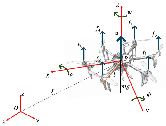
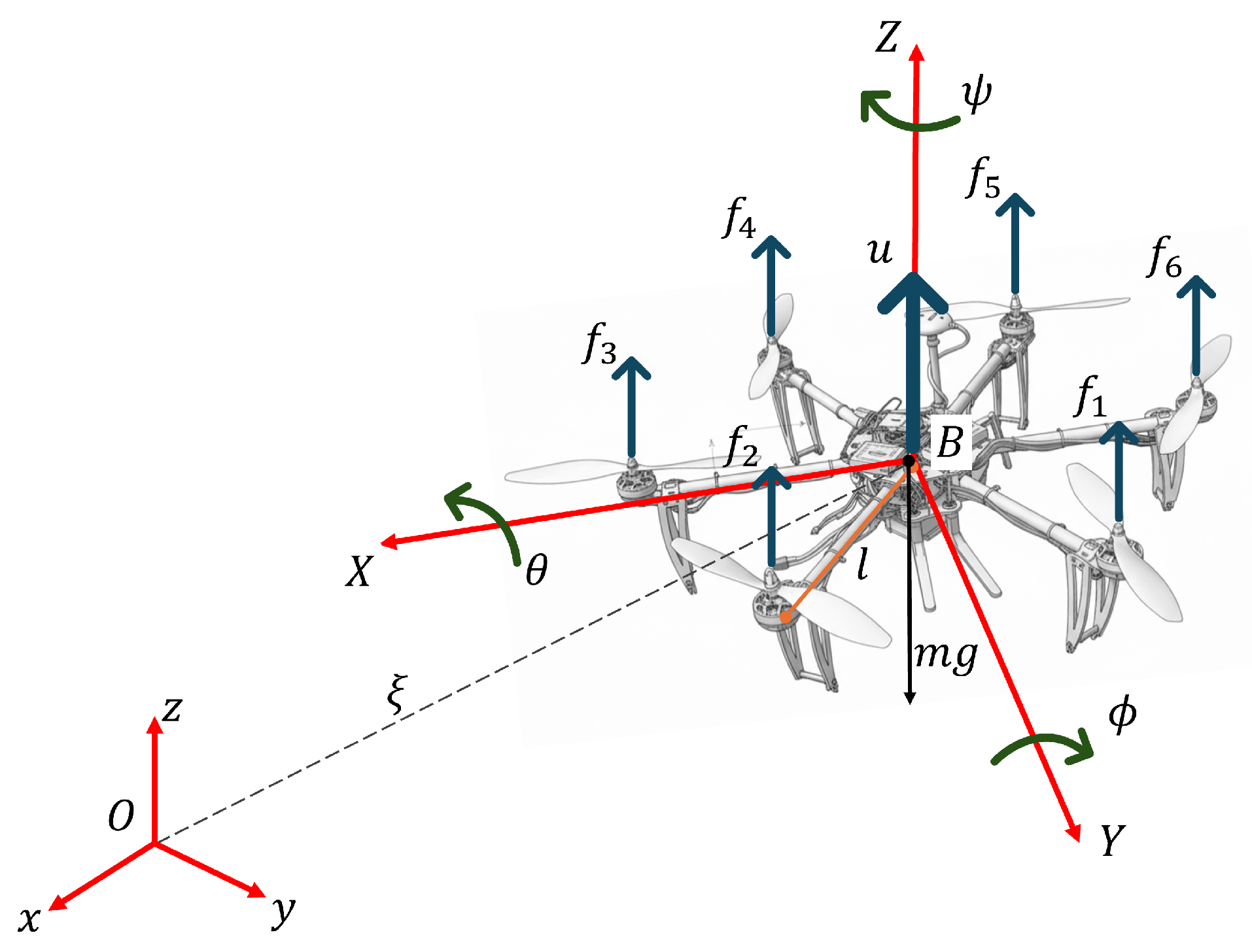
According to [20] the UAV can be modeled as a rigid body as follows. The UAV generalized system are where and are the traslational and rotational coordinates. Figure 1 represents the hexarotor aircraft diagram where the longitudinal, lateral and vertical axes are represented in the inertial frame and the body fixed coordinate frame is presented as . represents the force generated by i-rotor where . A set of aerodynamic constants are represented by k, the angular velocity of each rotor is represented by , the distance from the center of the mass to the rotors is represented by d and m represents the UAV mass and the acceleration due gravity is represented by g.
Figure 1.
Hexarotor aircraft diagram.
The total thrust is defined as and the torque is defined as follows:
where and . Therefore, the translational subsystem dynamical model is represented as follows:
and the rotational subsystem dynamical model is represented as follows
where inertia matrix is represented by and represents the Coriolis, centrifugal and centripetal forces vector.
2.1.1. Altitude Control
From (2) it is clear that the altitude z can be stabilized using the following linearizing control input:
Substituting (4) into the altitude dynamics of (2) yields
where is the input of the linearized system which can be selected as
where and is the desired altitude. After that, to stabilize the dynamics of x and y, we proceed to introduce (4) into the horizontal dynamics of (2) and assuming that and leads to
For the horizontal model (6) and (7), and are the corresponding control inputs of the system, these inputs also represent the trajectories to be tracked by attitude angles in order to regulate the horizontal motion, then let us define the desired trajectory as
where with and with . Assuming that and the state feedback controls (8) and (9) will transform the horizontal dynamic model (6) and (7) into
2.1.2. Robust Position Control Algorithm
Position control is the core function that enables Unmanned Aerial Vehicles (UAV), also known as drones, to perform specific tasks autonomously and precisely. In this case, a robust control technique is developed.
The UAV’s navigation depends on the position and speed estimate obtained from GPS. A state feedback control algorithm is used for aircraft position control. From (2), the lateral, longitudinal, and altitude control algorithms are proposed below. Therefore, the position control algorithm aims to track the trajectories provided by desired angles . For this purpose, let us introduce into a change of the input variables as follows:
resulting in the following dynamics:
The Lyapunov function is proposed as
where represents the ith element of the vector , and represent the ith diagonal elements of the positive matrices and , respectively. The Lyapunov function candidate is positive definite since and is a positive radially unbounded function. The time derivative of (12) is given as
which can be rewritten as
where Tanh is used to denote the vector containing the satured Euler angles, this vector is written as follows:
Using Property 2 leads to
Now, we introduce the saturated PD control:
where , are positive diagonal matrices. Notice that the controller’s saturation level is fixed through and while the state’s speed convergence is controlled trhough and . Substituting the control law in (15) leads to
Finally it follows that . Therefore, the origin is stable and the solutions and are bounded.
2.1.3. Safe Landing
In the event of a position estimate failure due to a loss of GPS signal, a safe zone search mode (a flat area) is activated, and then a safe landing algorithm is activated. The UAV holds its altitude using the height estimate from the depth camera ().
where s is the standard deviation of the UAV height. The differential depth algorithm evaluates the standard deviation of the UAV’s height relative to the ground.
3. Materials and Methods
The purpose of this article is to enable a drone perform an autonomous landing in GPS-denied environments by detecting a flat or regular terrain using a depth camera with an onboard companion computer. The system is designed to operate with low computational cost, ensuring online performance on resource-constrained hardware.
The landing decision is triggered when a flat surface is detected for at least 4 s, based on depth information captured by the camera. The onboard computer handles all processing and communicates with the Flight Controller Unit (FCU) through a MAVLink connection.
As illustrated in Figure 2, the vehicle begins the process by executing a predefined mission or normal flight mode. A condition is then evaluated to determine the availability of GPS. If GPS is available, the vehicle continues its mission. Otherwise, the depth camera begins capturing ground information.
Figure 2.
Flowchart of system operation.
Five ROIs (Regions of Interest) are defined in the depth image, and the mean distance within each region is calculated. Using these values, the system computes the standard deviation across all ROIs. A low standard deviation indicates that the terrain is sufficiently flat to permit landing, whereas a high deviation suggests irregular or unsafe landing conditions.
3.1. Safe Landing Zone Prediction
Two strategies were examined to estimate surface flatness for safe UAV landing. Among them, the ROI-based approach demonstrated higher reliability, making it the preferred method for real-time implementation during flight experiments.
The first, and not implemented approach, involved dividing the depth image into 16 equally sized grid cells. Each pixel within a grid measured the distance between the surface and the camera. The STD of the pixel distances was computed for each grid, and a color-coded message was displayed on the visual interface: green for grids with low STD (flat regions), and red for those with high STD (irregular regions). However, this method proved to be overly sensitive, as minor variations in depth, often caused by lighting artifacts or small surface irregularities, significantly increased the standard deviation, leading to false negatives for otherwise regular surfaces.
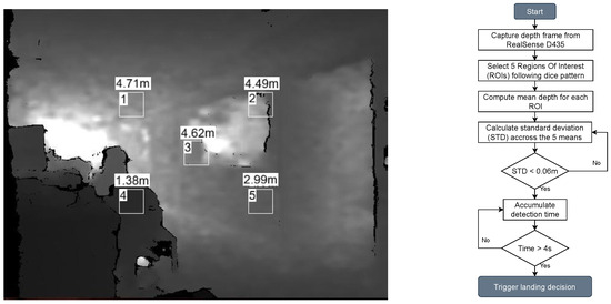
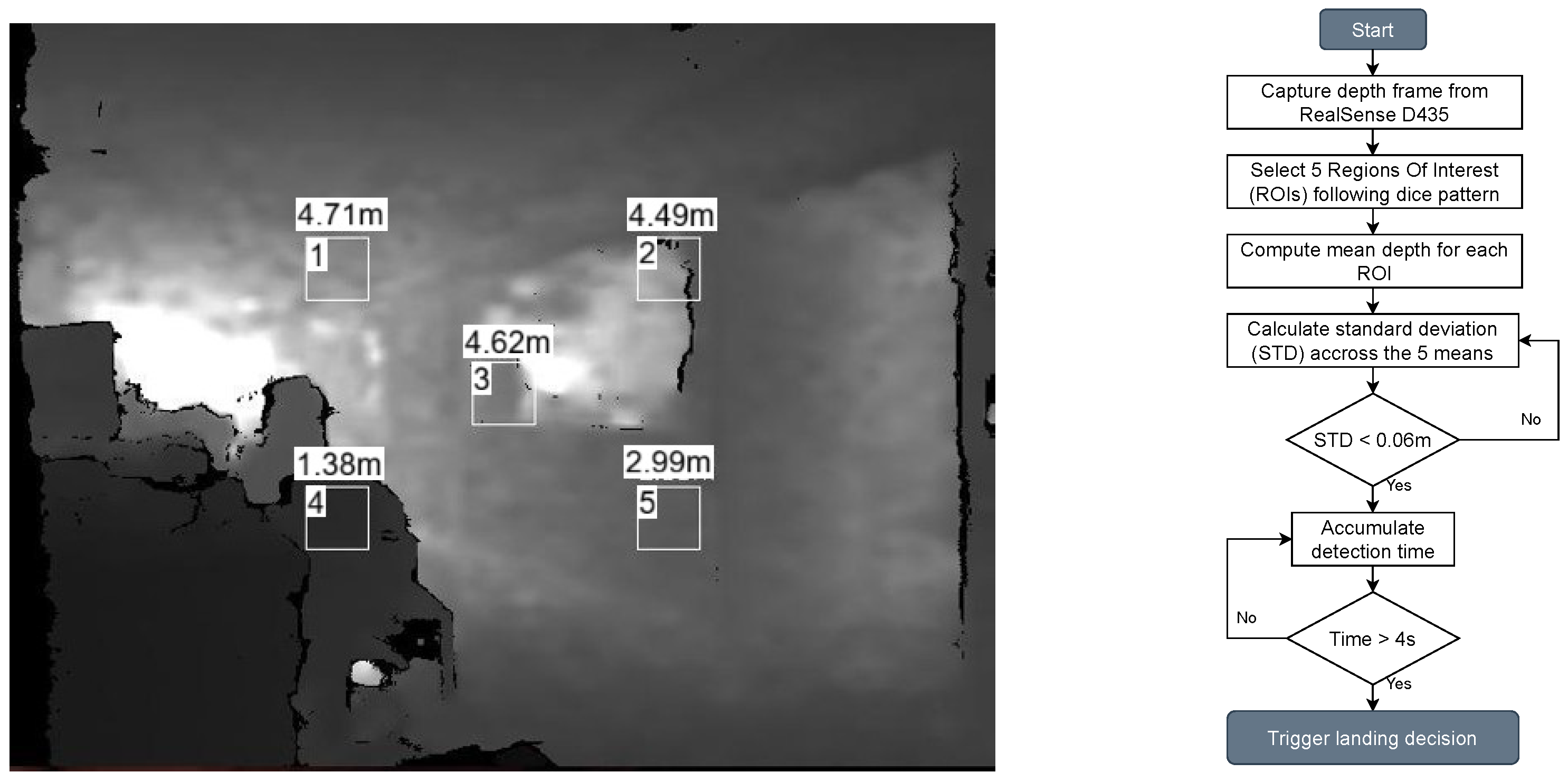
To address this issue, a second, more robust approach was implemented where five ROIs were selected based on a pattern resembling the number five on a dice with dimensions of pixels each, as shown in Figure 3. As before, each pixel measured the distance to the surface, but unlike the first method, the mean depth for each ROI was calculated and a single standard deviation value across the five means was then computed. Although the spatial STD for each ROI is calculated instantaneously at every depth frame, a temporal confirmation window is employed to ensure stability in the flatness estimate. The depth camera provides depth frames at 30 Hz; therefore, a 4 s confirmation period corresponds to approximately 120 consecutive frames. A landing command is triggered only if the global STD condition (STD m) remains satisfied throughout this time window. This temporal criterion prevents false detections caused by transient noise, vibrations, or momentary motion of the UAV.
Figure 3.
ROI approach on the left, which shows the five labeled image patches (1–5) with their respective mean distances above each square. Flat surface estimation flowchart on the right.
This revised method was significantly less sensitive to noise and more effective in identifying flat surfaces under real-world conditions.
3.2. Software Interfaces
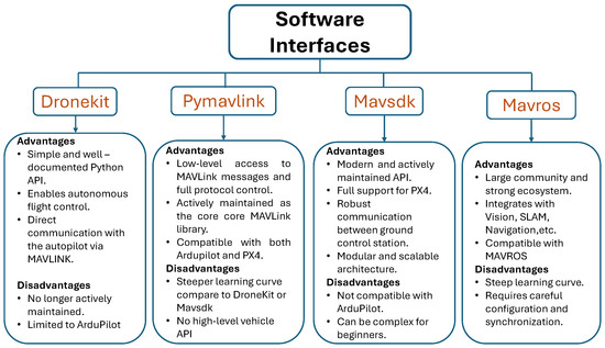
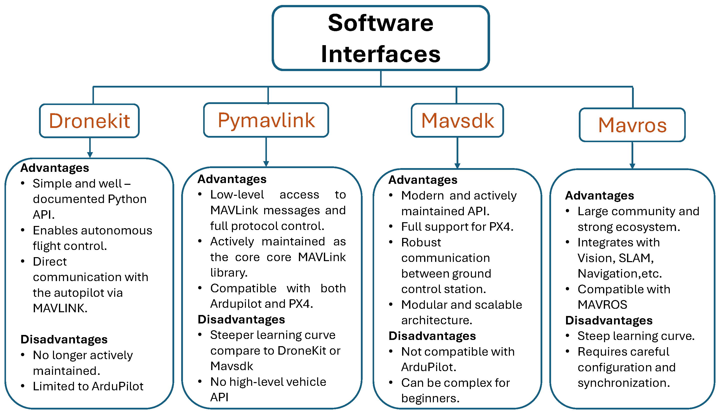
For the interaction between components a software interface that allows communication between the flight controller and the companion computer must be selected. Figure 4 shows the main software interfaces and some of their advantages and disadvantages to select one. Dronekit is a well-documented API, however it is not longer actively maintained. Mavsdk is a modern API but is not compatible with Ardupilot. Mavros is a good choice due to its large community and strong ecosystem, however it requires careful configuration when the purpose of this article is to keep the research work simple and with low computational cost. Therefore pymavlink was chosen due to its compatibility with both Ardupilot and PX4 and its active maintenance
Figure 4.
Software interfaces analysis chart.
A lightweight Python 3.6.9 script using the pyrealsense2 and pymavlink libraries extracts real-time distance measurements from the depth image’s pixels and formats them as MAVLink messages. These messages are transmitted at 5 Hz to the FCU over a direct USB serial connection. This approach eliminates the overhead of ROS-based pipelines, offering a minimal, reproducible, and low-latency integration path.
3.3. CNN-Based Landing Zone Classification
A lightweight Convolutional Neural Network (CNN) was trained using the mean depth values from the five ROIs as input features, with the label determined by the flatness condition (STD < 0.06 → safe). The dataset consisted of 743 samples (612 safe, 131 unsafe). The proposed 1-D CNN architecture included one convolutional layer (8 filters, kernel = 2), a fully connected layer of 8 neurons, and a sigmoid output neuron.
Input features were standardized to zero mean and unit variance, and the dataset was divided into 80% for training and 20% for validation. The network was trained for 20 epochs using the Adam optimizer and binary cross-entropy loss fucntion.
where is the true label and the predicted probability.
The model achieved a validation accuracy of 96.6%, demonstrating that the CNN can accurately classify surface flatness based solely on numerical ROI data. This confirms the feasibility of integrating a small, computationally efficient neural model into the onboard landing-decision module.
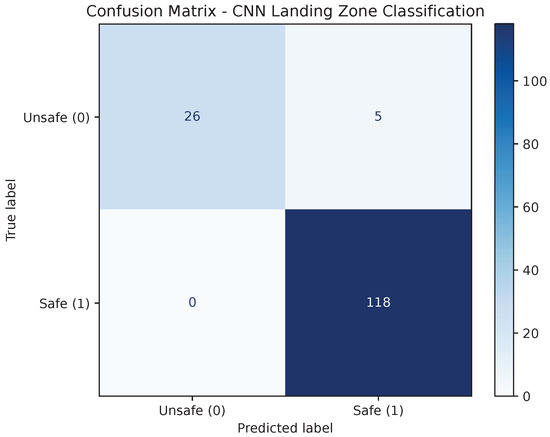
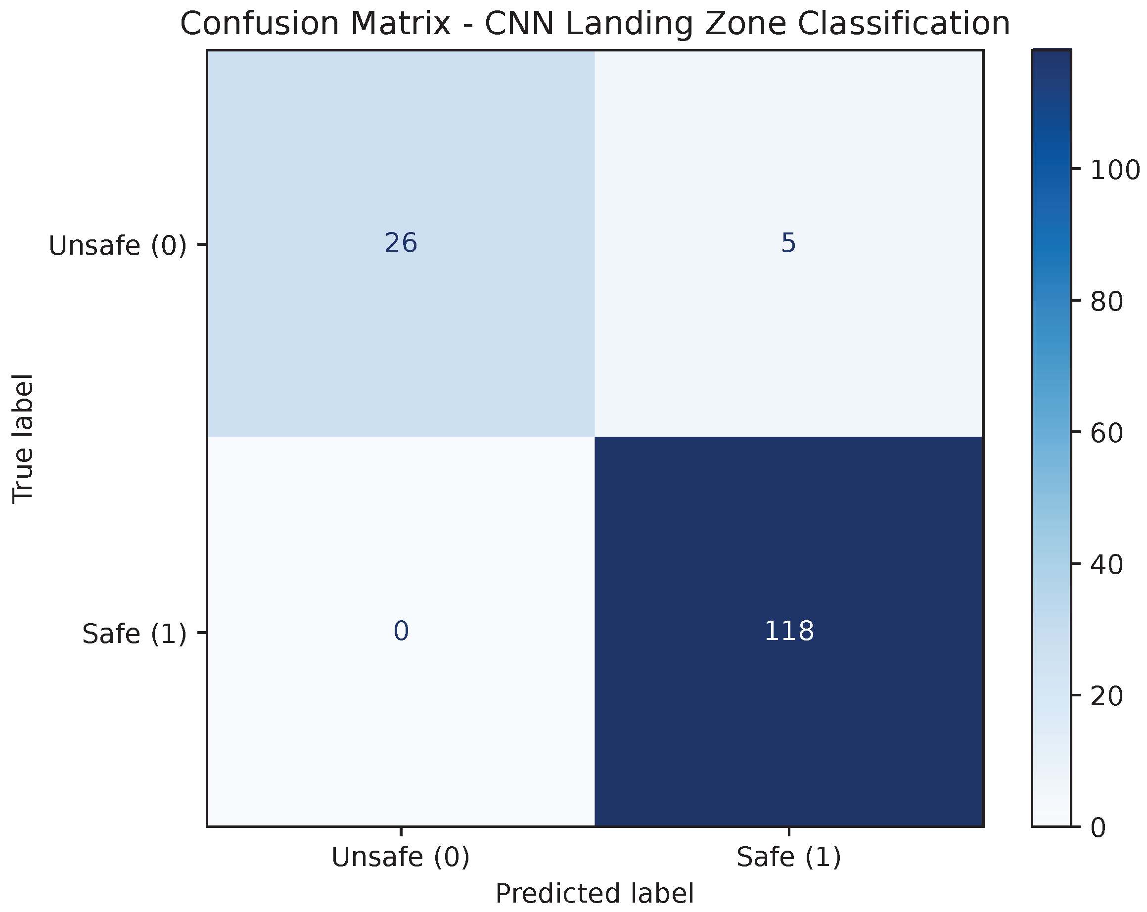
Figure 5 shows the confusion matrix for the CNN classifier. The model correctly identified 118 of 118 safe samples and 26 of 31 unsafe samples, reaching an overall accuracy of 96.6%. The network achieved a precision of 95.9% and a recall of 100% for the safe class as shown in the second row of Table 1, indicating that it never misclassified a safe landing area as unsafe. The few misclassifications corresponded to marginal cases where the surface standard deviation was near the decision threshold (STD ≈ 0.06 m). These results confirm that the proposed lightweight CNN can reliably infer landing safety using only numerical depth-derived features, with minimal computational cost.
Figure 5.
Confusion matrix of the CNN classifier for landing zone detection.
Table 1.
Performance metrics of the CNN classifier on the held-out test set ().
4. Results
A series of experimental tests were conducted to evaluate the proposed landing-zone detection system under diverse operating conditions. The experiments included flights over both flat and irregular surfaces, at different ground altitudes and UAV altitudes, as well as trials performed under external disturbances such as wind gusts and low-light (night) environments. The objective was to assess the robustness of the proposed method in terms of precision, recall and false-trigger rate. Results from repeated trials demonstrated consistent detection performance across varying conditions. It was observed that the UAV altitude plays the most critical role in maintaining reliable flatness estimation, as the spatial resolution of the depth camera decreases with increasing altitude, reducing the sensitivity of surface variation detection. Nevertheless, the proposed approach remained stable and responsive within the tested operational envelope, accurately identifying safe landing zones even in the presence of environmental disturbances.
4.1. Experimental Hardware Setup
All experiments were conducted using a custom-built hexacopter equipped with a Holybro Pixhawk 6X flight controller (Hong Kong, China) running the ArduPilot firmware. The onboard companion computer was an NVIDIA Jetson Nano (4 GB), responsible for executing the depth-processing and CNN algorithms in real time. Depth perception was provided by an Intel RealSense D435 camera (Santa Clara, CA, USA) operating at a resolution of pixels and a frame rate of 30 Hz, connected to the Jetson through a USB 3.0 interface. The communication between the companion computer and the flight controller was established via a MAVLink serial connection. This hardware configuration offered sufficient computing capability to run the proposed algorithms onboard without exceeding 40% CPU utilization, ensuring real-time performance during flight tests.
4.2. Experimental Tests
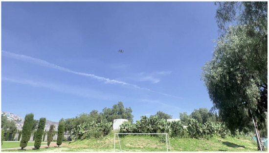
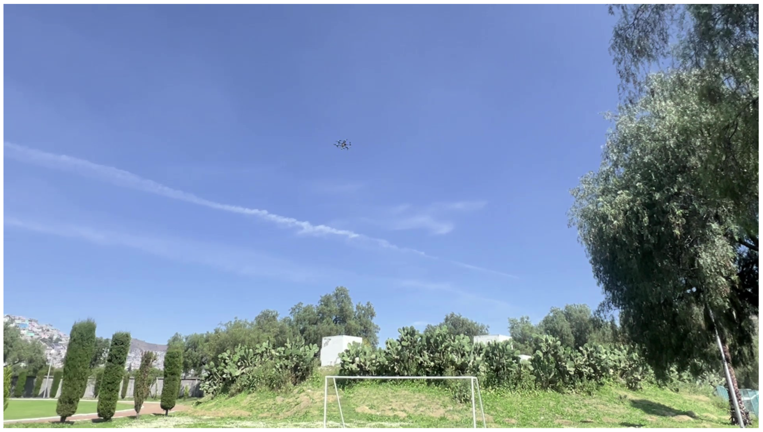
The first section of experimental tests were carried out out to obtain and analyze data purely, where sensor data was captured online during flight and subsequently analyzed offline. For these initial tests, the pilot had control over the drone at all times, and the platform operated without GPS. Prior to outdoor experimentation (see Figure 6), extensive bench tests were conducted to verify the performance of the vehicle, the depth camera, and the responsiveness of the FCU to companion computer commands.
Figure 6.
Actual zone of the second final test with an object in a flat zone.
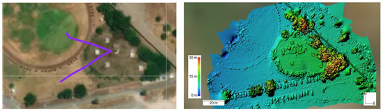
After validating these conditions with pilot-controlled trials, three experiments were performed in full autonomous mode, where the UAV executed the descent and landing without human intervention. These autonomous tests were carried out with 12 m above the ground where the camera’s resolution still works perfectly, and served to confirm the practical functionality of the proposed method. Figure 7 shows the UAV trajectory taken over an uneven surface on the left, and the digital elevation model of the monitored area on the right. The difference in height from the terrain flown over at 15 m to 30 m at the tops of nearby trees.
Figure 7.
Horizontal trajectory is shown by a purple line over the map and Digital Elevation Model (DEM) of the monitored area.
4.2.1. First Initial Test
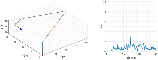
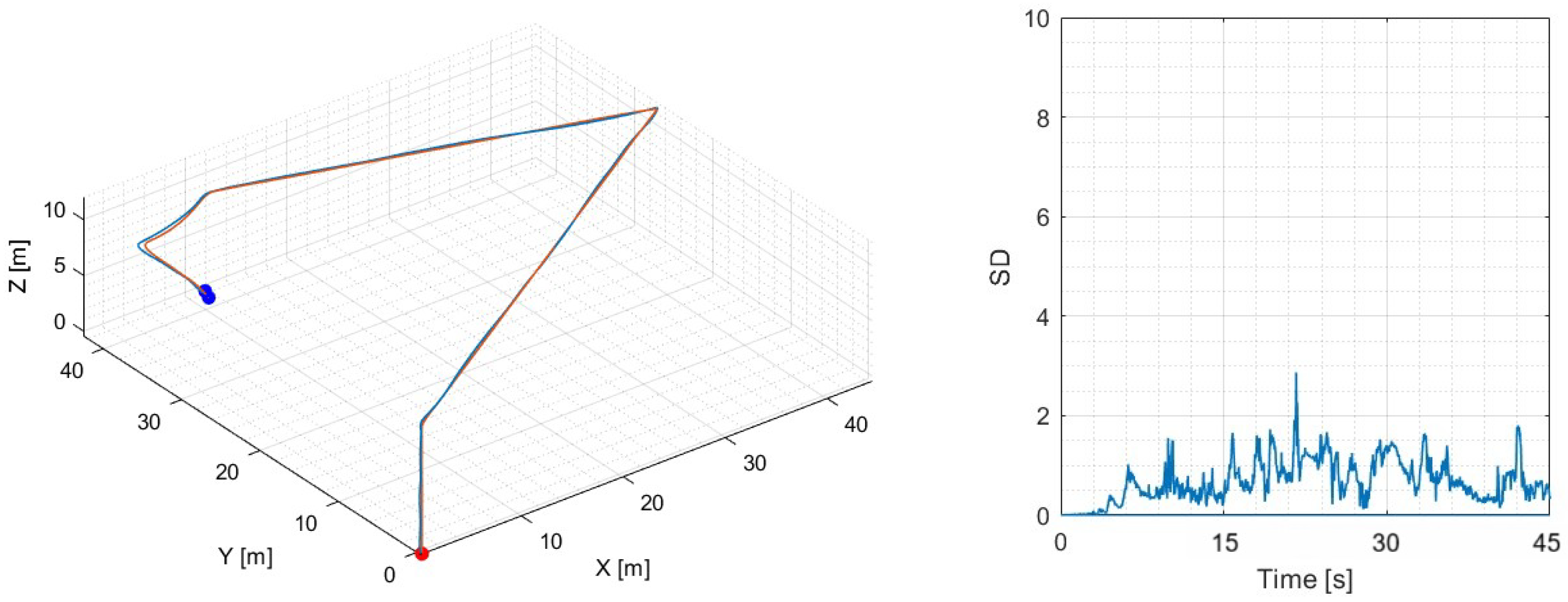
The first flight test consisted of a simple takeoff–hover–land maneuver over a flat surface. During hover, depth data from the surface was captured and later analyzed to verify consistency. For grass surfaces, the expected standard deviation is below 0.09 m, which serves as a baseline for flat but naturally irregular terrain. As shown in Figure 8, the measured standard deviation remained mostly below 0.05 m, confirming the reliability of the method under these conditions. The 3-Dimensional trajectory and the standard deviation of the ground are shown in Figure 8. High values of the standard deviation show that safe landing zones are not found.
Figure 8.
Flight Test 1: UAV trajectory where the orange line is the setpoint trajectory, blue line is the estimated trajectory, red point is the start point, blue point is the end of the trajectory and on the right standard deviation of the monitored area.
4.2.2. Second Initial Test
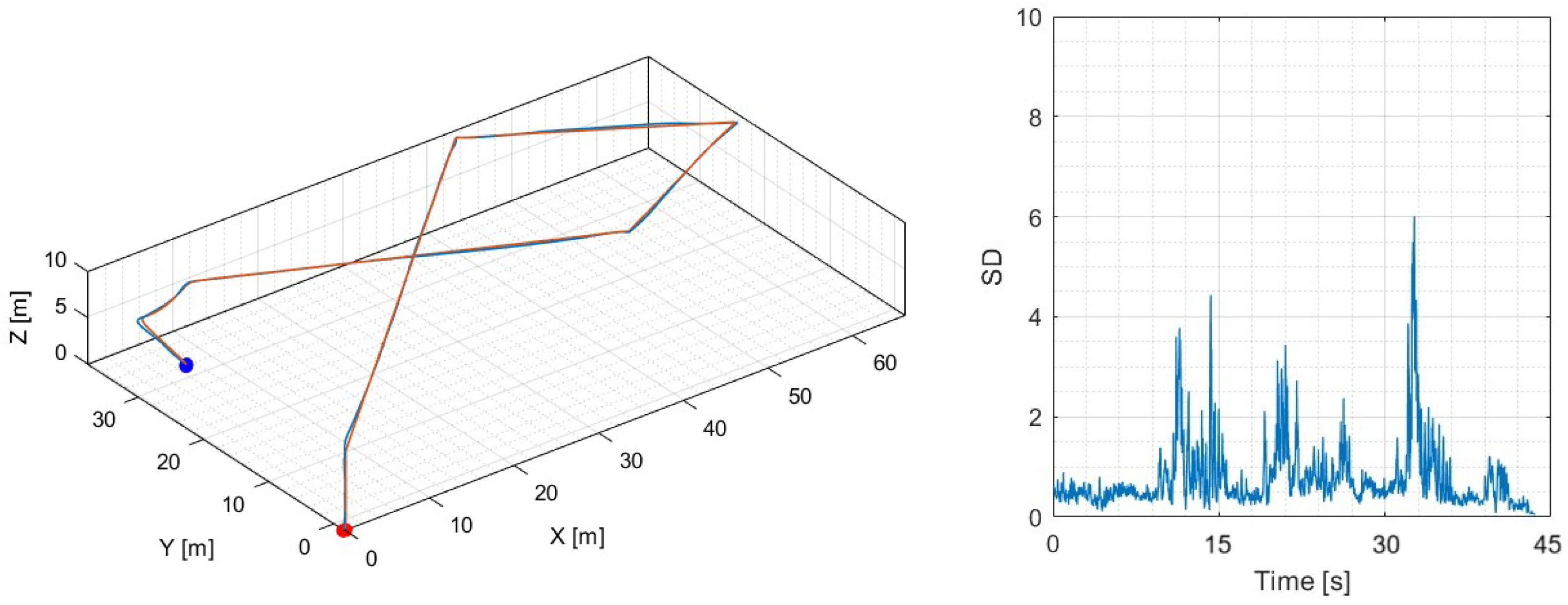
For the second test, the vehicle follows a different trajectory in the same area as the previous one. Figure 9 shows that the standard deviation is affected when the UAV changes its orientation from horizontal to follow the reference trajectory. Unlike a low STD throughout the entire flight, a high STD is now expected at a certain point in the flight, as the presence of objects makes the landing surface uneven. A measurement greater than 0.1 m is considered uneven.
Figure 9.
Flight Test 2:UAV trajectory where the orange line is the setpoint trajectory, blue line is the estimated trajectory, red point is the start point, blue point is the end of the trajectory and on the right standard deviation of the monitored area.
4.2.3. Third Initial Test
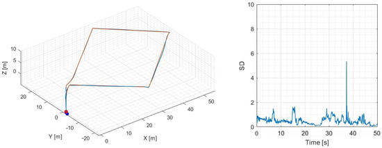
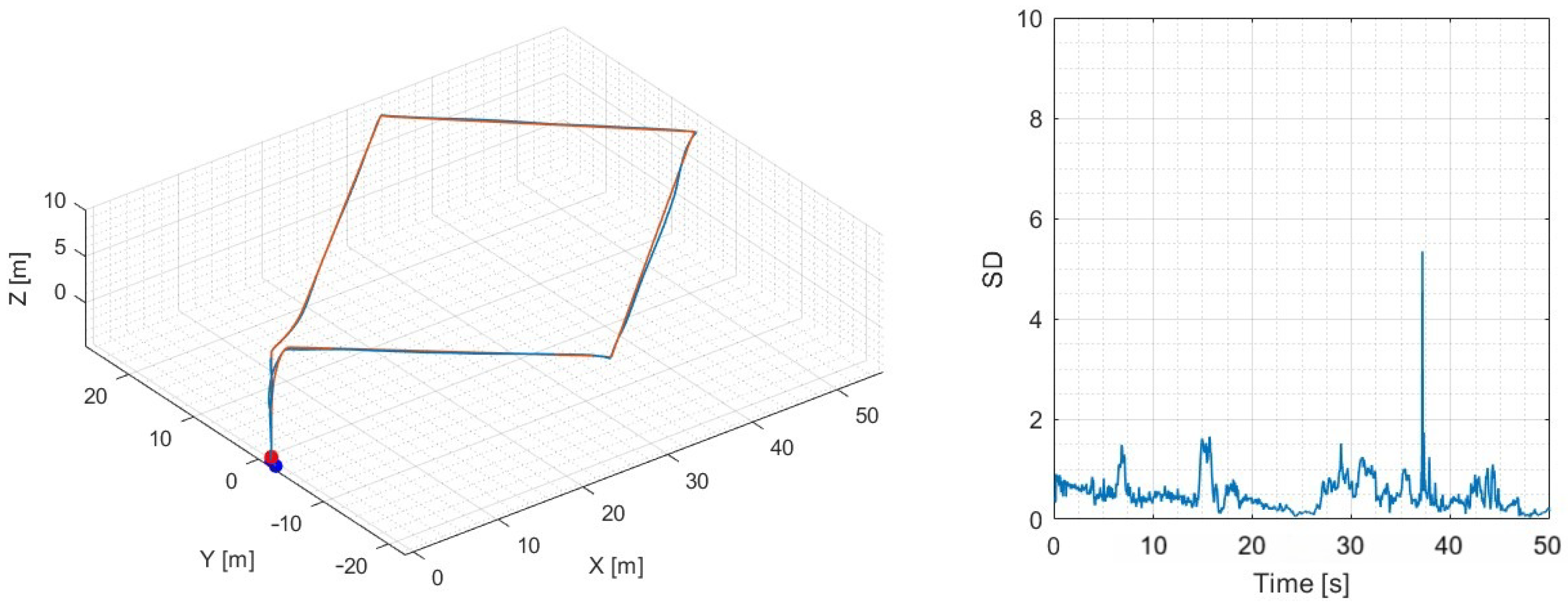
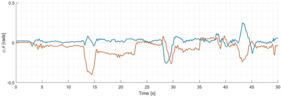
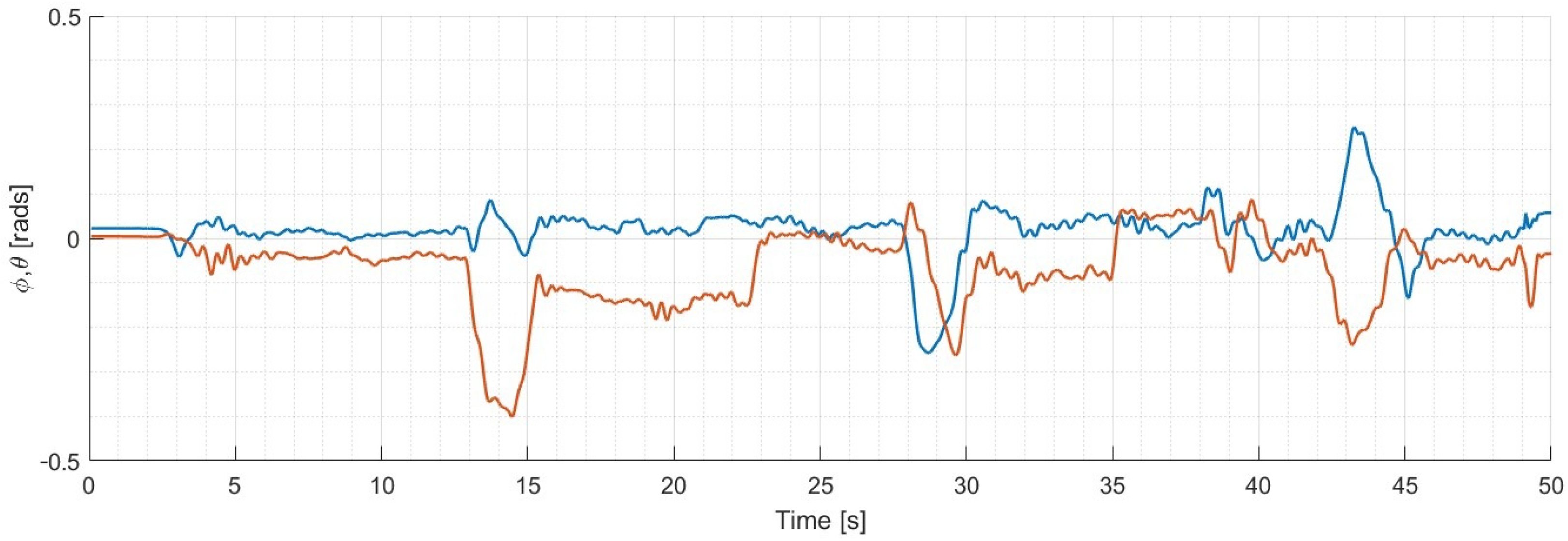
Figure 10 shows the UAV’s trajectory over a regular surface. However, changes in orientation during the maneuvers required for horizontal movement of the UAV also alter the estimation of flat terrain, generating an erroneous and irregular estimate of the monitored area. The UAV’s roll and pitch angles during horizontal movement maneuvers are also shown in Figure 11.
Figure 10.
Flight Test 3: UAV trajectory where the orange line is the setpoint trajectory, blue line is the estimated trajectory, red point is the start point, blue point is the end of the trajectory and on the right standard deviation of the monitored area.
Figure 11.
UAV attitude: the orange line represents the roll angle and the blue line the pitch angle.
4.2.4. Autonomous Mission Flight Test
The UAV hovers on a flat surface. However, the descent is no longer performed by the pilot; it is activated automatically when the vehicle loses GPS signal and detects a standard deviation of less than 0.06 m for at least four seconds, indicating that the drone has found a flat area and activated landing mode.
In the second and final test, a test was performed to differentiate a flat area from an uneven area. The scenario is set up with an object in the middle of a flat area of grass, where the drone must be able to identify if the area is safe to land. The UAV flies over different objects, identifying them as an uneven area; therefore, it should not activate landing mode. However, when moving to a flat area, it should estimate a low standard deviation and descend autonomously.
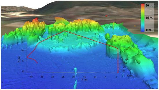
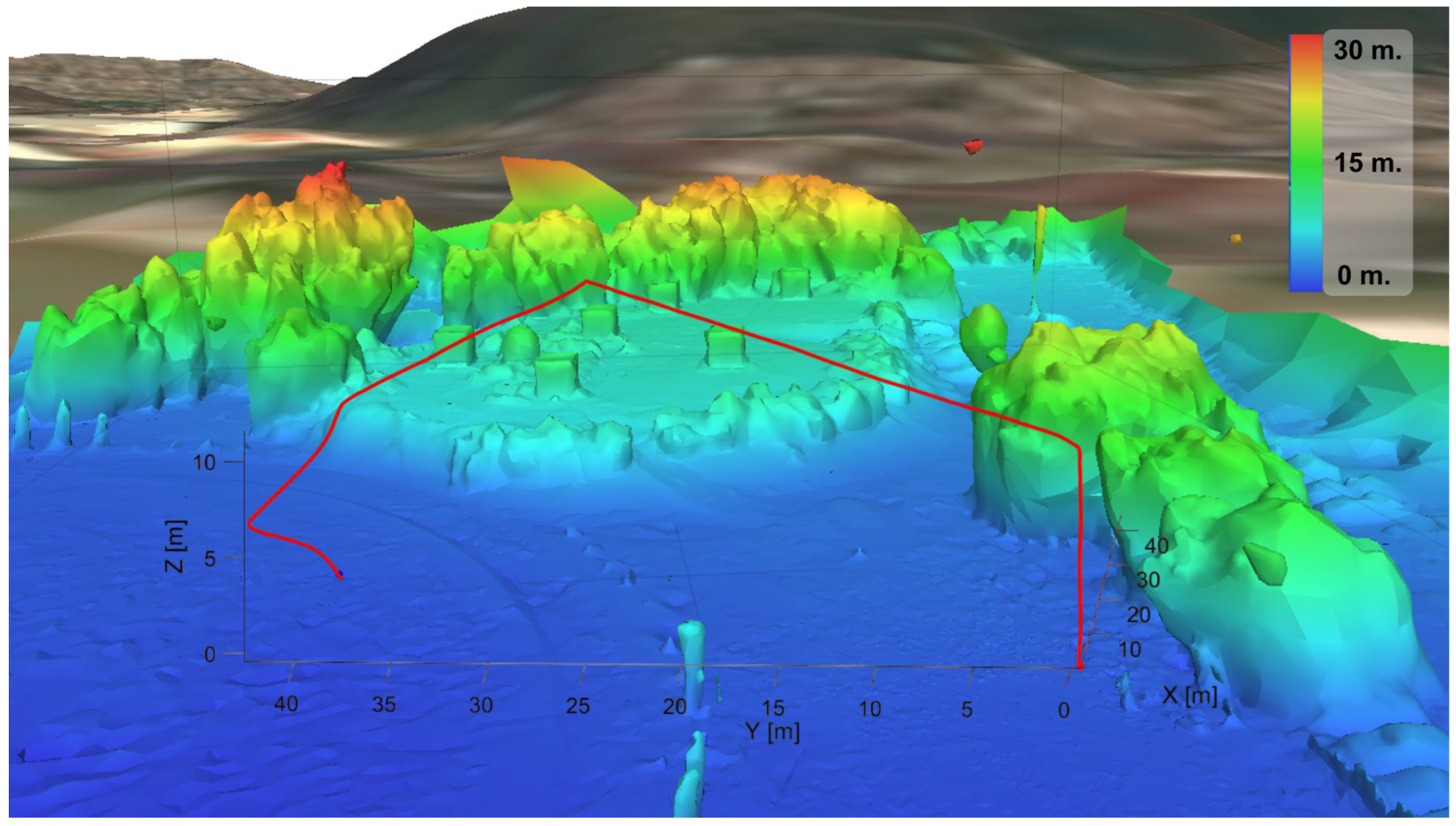
The system was validated with QGroundControl’s MAVLink Inspector, which confirmed the correct flight mode change when the standard deviation is low for more than 4 s, and it subsequently landed autonomously. The distance data was received and processed correctly. Finally, Figure 12 shows the flight path and the estimate of the change in terrain height during the flight.
Figure 12.
UAV trajectory on a reconstruction elevation map.
5. Conclusions
This research work presented a lightweight and effective approach to enable a safe autonomous landing when a flat zone is detected for UAVs in GPS-denied environments, using depth perception and online onboard processing. By evaluating surface flatness with the standard deviation across five selected regions of interest, the proposed method demonstrated robustness against noise while maintaining low computational requirements suitable for resource-constrained companion computers.
The experimental results confirmed that the system can reliably differentiate between flat and irregular terrains, correctly triggering land mode only under safe conditions. The integration of the depth camera and the flight controller unit via a minimal pymavlink-based pipeline ensured real-time responsiveness without the involvement of more complex frameworks. In addition, a compact one-dimensional CNN model was developed to classify surface safety based solely on numerical depth features, achieving a validation accuracy of 96.6%. This neural module complements the rule-based flatness estimator by providing an additional learned perception layer, further improving reliability in diverse environmental conditions. Overall, the proposed system enhances the safety and autonomy of UAV operations in scenarios where GPS is unavailable or unreliable. Future work is discussed in the following subsection.
Future Work
For future developments, the drone is expected to perform an autonomous displacement, having awareness of nearby obstacles to find the most suitable flat area and execute its descent. This will be achieved by integrating different sensors such as LiDAR or stereo vision that will provide enough data for the vehicle to have a good environmental perception. Moreover, optical flow sensors could be integrated to have a better position and altitude estimation in order to perform more reliable flights and have a better stability. This improvements will progressively extend the system toward full autonomy.
Author Contributions
Conceptualization and project administration, S.S. and J.F.; methodology and data curation, I.G.-H.; software and virtualization, M.A.C.; validation and formal analysis, R.L. All authors have read and agreed to the published version of the manuscript.
Funding
This research received no external funding.
Data Availability Statement
The original contributions presented in this study are included in the article. Further inquiries can be directed to the corresponding author.
Acknowledgments
The authors are grateful to Secretariat of Science, Humanities, Technology and Innovation (CECIHTI) for its support.
Conflicts of Interest
The authors declare no conflicts of interest.
Abbreviations
The following abbreviations are used in this manuscript:
| UAVs | Unmanned Aerial Vehicles |
| GPS | Global Positioning System |
| HEAC | Homography Estimation and Adaptive Control |
| ALS | Airborne Laser Scanning |
| DSM | Digital Surface Models |
| FCU | Flight Controller Unit |
| VTOL | Vertical Take-Off and Landing |
| LiDAR | Light Detection and Ranging |
| SLAM | Simultaneous Localization Furthermore, Mapping |
| R-CNN | Regional Convolutional Neural Network |
| ROI | Region Of Interest |
| UGV | Unmanned Ground Vehicle |
| EKF | Extended Kalman Filter |
| POMDP | Partially Observable Markov Decision Process |
| CNN | Convolutional Neural Network |
References
- Lu, Z.; Liu, F.; Lin, X. Vision-based localization methods under GPS-denied conditions. arXiv 2022, arXiv:2211.11988. [Google Scholar]
- Patterson, T.; McClean, S.; Morrow, P.; Parr, G.; Luo, C. Timely autonomous identification of UAV safe landing zones. Image Vis. Comput. 2014, 32, 568–578. [Google Scholar] [CrossRef] [Scilit]
- Kikumoto, C.; Harimoto, Y.; Yoshida, T.; Urakubo, T. Landing Area Detection Using Drone Aerial Images Based on Ground Segmentation and Dense Optical Flow. Trans. Inst. Syst. Control Inf. Eng. 2022, 35, 109–117. [Google Scholar] [CrossRef] [Scilit]
- Alam, M.S.; Oluoch, J. A survey of safe landing zone detection techniques for autonomous unmanned aerial vehicles (UAVs). Expert Syst. Appl. 2021, 179, 115091. [Google Scholar] [CrossRef] [Scilit]
- Sepahvand, S.; Amiri, N.; Masnavi, H.; Mantegh, I.; Janabi-Sharifi, F. A novel fuzzy image-based UAV landing using RGBD data and visual SLAM. Drones 2024, 8, 594. [Google Scholar] [CrossRef] [Scilit]
- Yang, T.; Li, P.; Zhang, H.; Li, J.; Li, Z. Monocular vision SLAM-based UAV autonomous landing in emergencies and unknown environments. Electronics 2018, 7, 73. [Google Scholar] [CrossRef] [Scilit]
- Patterson, T.; McClean, S.; Morrow, P.; Parr, G. Modelling safe landing zone detection options to assist in safety critical UAV decision making. Procedia Comput. Sci. 2012, 10, 1146–1151. [Google Scholar] [CrossRef] [Scilit]
- Singh, J.; Adwani, N.; Kandath, H.; Krishna, K.M. RHFSafeUAV: Real-time heuristic framework for safe landing of UAVs in dynamic scenarios. In Proceedings of the 2023 International Conference on Unmanned Aircraft Systems (ICUAS), Warsaw, Poland, 6–9 June 2023; pp. 863–870. [Google Scholar]
- Chatzikalymnios, E.; Moustakas, K. Landing site detection for autonomous rotor wing UAVs using visual and structural information. J. Intell. Robot. Syst. 2022, 104, 27. [Google Scholar] [CrossRef] [Scilit]
- Loureiro, G.; Dias, A.; Martins, A.; Almeida, J. Emergency landing spot detection algorithm for unmanned aerial vehicles. Remote Sens. 2021, 13, 1930. [Google Scholar] [CrossRef] [Scilit]
- Baidya, R.; Jeong, H. Simulation and real-life implementation of UAV autonomous landing system based on object recognition and tracking for safe landing in uncertain environments. Front. Robot. AI 2024, 11, 1450266. [Google Scholar] [CrossRef] [Scilit] [PubMed]
- Pieczyński, D.; Ptak, B.; Kraft, M.; Piechocki, M.; Aszkowski, P. A fast, lightweight deep learning vision pipeline for autonomous UAV landing support with added robustness. Eng. Appl. Artif. Intell. 2024, 131, 107864. [Google Scholar] [CrossRef] [Scilit]
- González-Trejo, J.; Mercado-Ravell, D.; Becerra, I.; Murrieta-Cid, R. On the visual-based safe landing of UAVs in populated areas: A crucial aspect for urban deployment. IEEE Robot. Autom. Lett. 2021, 6, 7901–7908. [Google Scholar] [CrossRef] [Scilit]
- Gonzalez-Trejo, J.A.; Mercado-Ravell, D.A. Lightweight density map architecture for uavs safe landing in crowded areas. J. Intell. Robot. Syst. 2021, 102, 7. [Google Scholar] [CrossRef] [Scilit]
- Castellano, G.; Castiello, C.; Mencar, C.; Vessio, G. Crowd detection in aerial images using spatial graphs and fully-convolutional neural networks. IEEE Access 2020, 8, 64534–64544. [Google Scholar] [CrossRef] [Scilit]
- Hinzmann, T.; Stastny, T.; Cadena, C.; Siegwart, R.; Gilitschenski, I. Free LSD: Prior-free visual landing site detection for autonomous planes. IEEE Robot. Autom. Lett. 2018, 3, 2545–2552. [Google Scholar] [CrossRef] [Scilit]
- Chen, L.; Yuan, X.; Xiao, Y.; Zhang, Y.; Zhu, J. Robust autonomous landing of UAV in non-cooperative environments based on dynamic time camera-LiDAR fusion. arXiv 2020, arXiv:2011.13761. [Google Scholar]
- Magrisso, Y.; Rivlin, E.; Rotstein, H. Local Trajectory Planning For UAV Autonomous Landing. arXiv 2021, arXiv:2111.00495. [Google Scholar] [CrossRef] [Scilit]
- Xin, L.; Tang, Z.; Gai, W.; Liu, H. Vision-based autonomous landing for the UAV: A review. Aerospace 2022, 9, 634. [Google Scholar] [CrossRef] [Scilit]
- Reyes, S.; Romero, H.; Salazar, S.; Lozano, R.; Santos, O. Outdoor haptic teleoperation of a hexarotor UAV. In Proceedings of the 2015 International Conference on Unmanned Aircraft Systems (ICUAS), Denver, CO, USA, 9–12 June 2015; pp. 972–979. [Google Scholar]




Disclaimer/Publisher’s Note: The statements, opinions and data contained in all publications are solely those of the individual author(s) and contributor(s) and not of MDPI and/or the editor(s). MDPI and/or the editor(s) disclaim responsibility for any injury to people or property resulting from any ideas, methods, instructions or products referred to in the content. |
© 2025 by the authors. Licensee MDPI, Basel, Switzerland. This article is an open access article distributed under the terms and conditions of the Creative Commons Attribution (CC BY) license (https://creativecommons.org/licenses/by/4.0/).