


Highlights
What are the main findings?
- A prescribed-time cooperative control law combining an extended state observer, a dynamic event-triggered mechanism, and a directly specified arrival instant is proposed for multi-UAV cooperative rendezvous/tracking, reducing inter-UAV communication by about 97%.
- The flight-time consensus error, the observer’s estimation error, and the LOS angle errors are each proven to converge within a designer-specified prescribed time, and the event-triggered mechanism is proven to be free of Zeno behavior.
What are the implications of the main findings?
- Designing the guidance gain from the worst-case algebraic connectivity of the candidate topology set keeps the law valid under arbitrary switching without retuning for each topology.
- Compared with existing prescribed-time and fixed-time methods, the proposed law cuts miss distance by about 84% and 42%, respectively, while also allowing the final arrival time to be fixed directly.
Abstract
To address time-varying communication topology, actuator response delay, and limited inter-UAV communication resources in the multi-UAV approach of a maneuvering target, this paper proposes a cooperative rendezvous/tracking control law combining a prescribed-time extended state observer (PTESO) with a dynamic event-triggered mechanism (DET). A three-state PTESO is designed whose observation error converges, within a prescribed time independent of the initial error, into a compact set related to the disturbance upper bound. Along the line-of-sight (LOS) direction, the remaining flight times of the UAVs are driven to consensus within a prescribed time toward a specified arrival instant via a threshold-adaptive DET; along the LOS normal direction, prescribed-time convergence of the elevation and azimuth angle errors is achieved through a time-varying-gain sliding surface. The guidance gains are designed from the worst-case algebraic connectivity of the candidate topology set, ensuring uniform validity under arbitrary switching. After accounting for first-order autopilot inertial dynamics, the command tracking error is proven uniformly ultimately bounded. Simulations of four UAVs cooperatively approaching a maneuvering non-cooperative object under periodic topology switching and actuator delay show an arrival-time deviation below 0.01 s, a terminal position error under 0.08 m, and 75–91 average inter-UAV triggers, outperforming existing prescribed-time/fixed-time cooperative guidance methods.
1. Introduction
As multi-UAV systems are increasingly deployed for time-critical coordination tasks, achieving simultaneous or sequenced arrival of multiple vehicles at a common location or moving object with limited onboard resources has become a practical problem across both civilian and defensive applications. Representative scenarios include cooperative search-and-rescue operations requiring multiple UAVs to reach a survivor location simultaneously from different directions, coordinated low-altitude airspace security tasks in which several UAVs must jointly track and approach a non-cooperative aerial object before it enters a protected zone, and time-synchronized logistics delivery. In all these cases, multiple UAVs converging on a common target simultaneously from different directions, according to a predetermined arrival sequence, improves task robustness and reduces the resource burden on any single vehicle. This is the fundamental reason why the cooperative guidance problem has attracted sustained attention. Around this objective, the design of cooperative guidance laws typically proceeds along two main lines: first, controlling the LOS direction so that the remaining flight times of the individual UAVs converge to consensus, achieving simultaneous or sequenced arrival; second, controlling the LOS normal direction to satisfy a prescribed terminal approach angle constraint. The leader–follower time-cooperation framework proposed by Jeon et al. [1] and the impact-time-control concept [2] laid the foundation for subsequent research, an approach that was later extended to angle-constrained guidance problems; the terminal attitude-angle-constrained guidance problem first proposed by Kim and Grider [3] subsequently gave rise to two main approaches, biased proportional navigation [4] and nonsingular terminal sliding mode [5]. In recent years, research unifying impact-time and terminal-angle constraints within the same framework has also been growing: Wang et al. proposed an impact-time- and angle-constrained guidance law based on a two-stage strategy [6], while Xie and Ma and Gong et al. respectively presented suboptimal guidance schemes accounting for both time and angle constraints against maneuvering targets [7,8].
Early cooperative guidance laws mostly employed sliding-mode control to achieve finite-time convergence of the time-cooperation error and the angle error, but the convergence-time upper bound of finite-time methods depends on the initial system state, making it difficult to specify a definite convergence bound prior to engineering implementation. The introduction of fixed-time and even prescribed-time stability theory resolved this issue [9,10], allowing the convergence time to be directly specified as a design parameter. This theory traces back to the fixed-time stabilization framework proposed by Polyakov [11], the time-varying feedback design that achieves regulation of nonlinear systems in prescribed finite time proposed by Song et al. [12], and the prescribed-time Lyapunov criteria given by Sánchez-Torres et al. and Jiménez-Rodríguez et al. [13,14]. Compared with the classical finite-time stability results of Bhat and Bernstein [15], the latter further eliminates the dependence of the convergence instant on the initial state. In terms of disturbance estimation, Hu et al. designed a generalized super-twisting extended state observer for angle-constrained terminal sliding-mode guidance [16], He et al. introduced prescribed-time convergence properties into nonsingular terminal sliding-mode guidance and validated it in a coordinated multi-agent formation scenario [17], and Yi et al. designed an observation-shared cooperative look-angle tracking guidance law for the case of partial seeker failure [18]. More recently, Ma et al. [19] proposed a robust prescribed-time observer-based sliding-mode control framework validated in a flight-control application, further illustrating the applicability of prescribed-time observer design to aerospace systems; however, none of these works, including [16,17,18,19], considered the practical constraints of inter-UAV communication.
The above works mostly assume that the inter-UAV communication topology is fixed, which departs from engineering reality—communication links may change dynamically due to interference, occlusion, or bandwidth limitations. Consensus theory under switching and directed topologies was first systematically established by Olfati-Saber and Murray [20]. Ning et al. proved that fixed-time consensus can still be maintained under switching topologies for multi-agent systems with discontinuous inherent dynamics [21]; Li et al. further presented a fully distributed consensus protocol design method under directed graphs [22]. In the cooperative guidance problem, a series of explorations of consensus maintenance under switching topologies has already emerged: Sinha and Kumar extended prescribed-time consensus theory to cooperative rendezvous/guidance problems under fixed and switching networks [23]; Hou et al. designed a finite-time cooperative guidance law accounting for both switching topologies and terminal angle constraints [24]; and Ma et al. proved that prescribed-time consensus can still be maintained under switching topologies even with a superimposed dynamic event-triggered communication scheme [25], but this result was established within a general multi-agent-system framework and was not developed for three-channel cooperation in the guidance problem. This direction continues to advance rapidly: Qin et al. designed a bounded-gain prescribed-time cooperative guidance law for jointly strongly connected switching topologies, resolving the engineering-implementation difficulty of traditional methods in which the gain tends to infinity near the convergence instant [26], Ma and Guo designed a prescribed-time cooperative guidance law for intermittent communication scenarios [27], and Xu et al. extended prescribed-time consensus algorithms to multi-agent optimization problems with input disturbances [28]. In a related direction, Ma et al. [29] developed a three-dimensional prescribed-time cooperative guidance strategy based on impulsive pinning control, achieving multi-agent consensus without requiring continuous inter-agent communication. However, neither the guidance-problem explorations of [23,24,25], nor the consensus-theory advances of [26,27,28], nor the impulsive-pinning strategy of [29] took actuator lag into account.
The event-triggered mechanism for reducing inter-UAV communication load has likewise attracted attention. The static-triggering framework proposed by Tabuada [30] and the dynamic-triggering extension proposed by Girard [31]—the latter extending the average inter-event interval and excluding Zeno behavior through the introduction of an internal auxiliary variable—constitute the theoretical foundation of event-triggered control. Ning et al. further combined this mechanism with prescribed-time convergence and provided proofs of its preservation [32,33], while Zhang et al. gave a dynamic time-varying event-triggered consensus scheme with a designable minimum inter-event time [34]. When this theory was introduced into the guidance problem, existing works have mostly remained confined to discussing a single non-ideal factor under a fixed-topology assumption: Zhai and Yang addressed the effect of autopilot lag on trigger error and cooperation accuracy [35], Zhang et al. verified the preservation of prescribed-time convergence properties under event-triggered conditions [36], and Li et al. designed a cooperative guidance law based on a prescribed-time performance function and a fault-tolerance mechanism for false-data-injection-attack scenarios [37]. Zhu et al. are among the few works simultaneously accounting for event-triggered communication and terminal angle cooperation [38]. None of these studies incorporated topology switching, actuator dynamics, and the event-triggered mechanism within a single framework. The effect of actuator lag on guidance accuracy is itself not a new problem—the command-to-actual acceleration deviation caused by first-order or higher-order inertial lag, if left uncompensated, erodes the theoretical convergence guarantee. Xu et al. recently proposed a fixed-time convergent guidance law accounting for both angle constraints and autopilot-lag compensation, but this study addressed only the single-UAV case and did not involve multi-UAV cooperation or topology switching [39]; Zhao et al. studied a multi-constraint cooperative guidance problem without actively controlling speed [40].
In summary, although the three practical engineering factors—switching communication topology, first-order inertial actuator dynamics, and the dynamic event-triggered mechanism—each already have a corresponding research foundation, and results combining event-triggering with prescribed-time convergence have already appeared at the level of general control theory [32,33], work that incorporates all three simultaneously into a unified prescribed-time cooperative guidance framework with rigorous theoretical proof remains scarce. The existing literature either assumes a fixed topology, neglects actuator lag, or confines the event-triggered mechanism to a single constraint or to general multi-agent systems rather than the complete three-channel cooperative guidance problem. To address this gap, this paper proposes a multi-UAV prescribed-time cooperative guidance law under the coexistence of periodic switching among candidate communication topologies and first-order inertial actuator dynamics. The main contributions are as follows.
- (1)
- For target maneuvering disturbance, a three-state prescribed-time extended state observer is constructed, achieving online estimation of the disturbance and its rate of change through a hyperbolic-tangent-type NPTS reaching law. Compared with existing finite-time or fixed-time extended state observers [16], the convergence instant of the proposed observer can be prespecified by the designer and is completely independent of the initial estimation error, providing disturbance compensation with a determinate convergence instant for subsequent guidance-law design.
- (2)
- The LOS-direction guidance law is designed with the specified arrival instant as the target, while the LOS-normal-direction guidance law achieves angle-error convergence through a prescribed-time sliding surface with a time-varying gain; the guidance gain is designed according to the worst-case algebraic connectivity of the candidate topology set, ensuring uniform validity under arbitrary switching within the candidate topology set.
- (3)
- A threshold-adaptive dynamic event-triggered mechanism is introduced to reduce inter-UAV communication load, and it is proven that under the dual non-ideal conditions of arbitrary switching among candidate topologies and first-order inertial actuator lag, the trigger interval still has a positive lower bound independent of the initial condition, no Zeno behavior occurs, and the command tracking error remains uniformly ultimately bounded. Existing event-triggered cooperative guidance research has only been carried out under fixed-topology or ideal-actuator assumptions [35,36,37,38]; this paper incorporates topology switching, actuator dynamics, and dynamic event-triggering into the same prescribed-time theoretical framework and provides rigorous proofs.
The interaction among the three non-ideal factors considered here gives rise to technical difficulties that do not arise from treating each factor in isolation. Topology switching requires the triggering threshold law in (43) to be designed around the worst-case algebraic connectivity rather than the instantaneous available under a fixed topology. The first-order actuator lag introduces a filtering delay between the commanded and actual accelerations that propagates into the trigger error through (42), slowing the decay of the triggering threshold during the transient stage, as discussed in Section 4.3; the layered prescribed-time requirement across the observer, LOS-direction, and LOS-normal-direction channels necessitates the composite Lyapunov construction , which has no counterpart when the three channels are analyzed independently. The remainder of this paper is organized as follows. Section 2 introduces the graph-theoretic foundations and lemmas related to prescribed-time stability and establishes the three-dimensional encounter kinematic model. Section 3 designs prescribed-time extended state observers (PTESOs) for the LOS direction and the LOS normal direction, respectively. Section 4 designs the LOS-direction and LOS-normal-direction cooperative guidance laws under candidate topology switching and actuator lag, introduces a dynamic event-triggered mechanism in the LOS direction, and proves the positive lower bound of the trigger interval as well as the uniform ultimate boundedness of the command tracking error under actuator lag. Section 5 presents numerical simulations of four UAVs cooperatively approaching and compares the results with the existing literature methods to verify the effectiveness and superiority of the proposed method. Section 6 concludes the paper and points out directions for future work.
2. Preliminaries and Problem Description
2.1. Graph Theory
The communication topology among UAVs is represented by the graph , where denotes the set of network nodes, denotes the edge set, and is the adjacency matrix. If information from UAV can be transmitted to UAV , then ; otherwise . For any , if , the graph is said to be undirected. If a connected path exists between any two nodes, the graph is said to be connected. The Laplacian matrix is defined as , expressed as
For an undirected connected graph , the matrix is symmetric positive semi-definite, with eigenvalues satisfying , where denotes the algebraic connectivity of graph . The connection matrix between the leader (virtual leader UAV) and the followers is , where if and only if the -th UAV can receive information from the virtual leader UAV, and otherwise. Define the augmented topology matrix . Then, under the condition that the graph is undirected and connected and at least one UAV is connected to the virtual leader, is positive definite, i.e., . The candidate topology set is assumed to be connected; let denote the worst-case lower bound, so that holds at any switching instant. Table 1 summarizes the key symbols used throughout this paper.
Table 1.
Notation.
2.2. Related Lemmas
Consider the following nonlinear system:
where is the state vector of the system, denotes a nonlinear function that is continuous on , and represents the initial state of the system.
Lemma 1
([10]). For , if
, then
Lemma 2
([27]). Consider the following nonlinear system:
where is the -dimensional state vector, is a nonlinear function, and denotes the initial state of the system. Consider a radially unbounded Lyapunov function with . If
where are constants, and and are time-varying functions expressed as
where
. When
, the following inequality holds:
Theorem 1.
Suppose there exists a radially unbounded function
such that
where and is the prescribed convergence time. Then the system satisfies and as , i.e., the system is prescribed-time stable.
Proof.
Consider the following first-order system:
Design the control law as:
Let , and construct the Lyapunov function:
Taking the time derivative of :
From :
Substituting control law (11) into (14):
Substituting (15) into (13) and using the identity :
Integrating both sides over :
That is
From (12), as , , and hence . Since is continuous in and strictly decreasing to zero, by the intermediate-value theorem for continuous functions, there exists such that .
Hence , and the control input is continuous at the convergence instant. □
2.3. Guidance Model Establishment
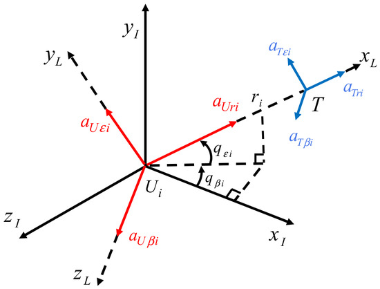
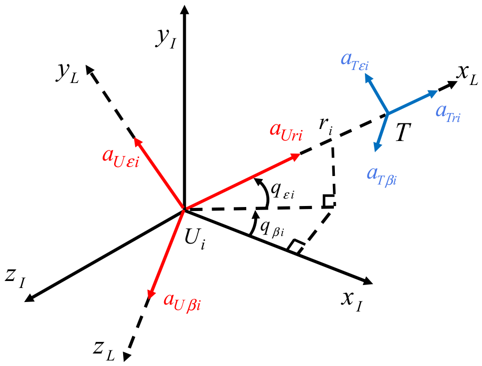
This paper considers UAVs cooperatively approaching a single maneuvering target in three-dimensional space. The encounter geometry is shown in Figure 1, where and denote the inertial coordinate system and the LOS coordinate system, respectively; and denote the -th UAV and the target, respectively; and denote the relative range and relative closing velocity between the UAV and the target, respectively; and denote the LOS elevation angle and LOS azimuth angle, respectively; and and denote the acceleration components of the UAV and the target, respectively, along the LOS, elevation, and azimuth directions in the LOS coordinate system.
Figure 1.
Three-dimensional encounter geometry.
Define the state variables , where are the desired elevation and azimuth angles, respectively. Then the three-dimensional guidance kinematics can be expressed as
where
This paper further considers the dynamics of the actuation mechanism (autopilot/servo loop). In the ideal case, Equation (20) assumes the acceleration command computed by the guidance law can be instantaneously applied to the airframe; however, the real autopilot exhibits response delay to commands. To this end, the following first-order inertial element is introduced to describe the transfer relationship between the commanded and actual accelerations:
where are the commanded accelerations computed and saturated/limited by the guidance law; are the actual accelerations applied to the airframe dynamics Equation (20); and are actuator time constants, whose magnitude is determined by the autopilot hardware bandwidth. The introduction of (21) means that in the dynamics Equation (20) are no longer the instantaneous output of the guidance law, but rather the true actuated quantities after first-order low-pass filtering, making the system model more consistent with engineering reality.
Assumption 1.
The target maneuver satisfies the local Lipschitz condition, i.e.,
Assumption 2.
During the guidance process, the relative range between the UAV and the target satisfies
, and the relative closing velocity satisfies
, where
are known positive constants. The robust gain
is taken as the maximum value of
over all UAVs to ensure
holds for every UAV. Since
is only an upper bound of the derivative of the target’s maneuvering acceleration rather than a precisely known quantity, the observer estimation error can only converge into a bounded neighborhood rather than converging exactly to zero.
Remark 1.
The range and interval specified in Assumption 2 are not imposed independently of the closed-loop dynamics but can be shown to be consistent with them. Defining
and differentiating along (20), the saturated command together with the disturbance bound from Assumption 1 yields so that the rate at which can drift away from its initial value is uniformly bounded by . It follows that once the design parameters satisfy the interval is positively invariant for over . Assumption 2 therefore reduces to a parameter-selection condition guaranteed by the closed-loop trajectory itself, rather than an unverifiable a priori restriction.
This paper designs a three-channel cooperative guidance law to achieve simultaneous rendezvous with a maneuvering target at a desired terminal approach angle, with the following specific objectives: (1) the estimated arrival instants of the individual UAVs converge to consensus within the prescribed time ; (2) the LOS angle errors converge to zero within the prescribed time ; and (3) the proposed guidance law preserves the above prescribed-time convergence properties under candidate topology switching and first-order inertial actuator dynamics, and the dynamic event-triggered mechanism does not exhibit Zeno behavior.
3. Prescribed-Time Extended State Observer (PTESO) Design
3.1. LOS-Direction PTESO Design
In the three-dimensional encounter dynamics system (20), the LOS-direction state equation can be written as
For the above system, based on Theorem 1, the LOS-direction prescribed-time extended state observer (PTESO) is constructed as follows:
where is the velocity estimation error; are the estimates of and , respectively; is the robust gain; and is the NPTS reaching law, defined as
where , is the time-varying prescribed time, .
Remark 2.
in (25) is naturally linearized near the origin, avoiding singularity of the fractional power; at large error,
, so the equivalent gain increases with the error, giving faster reaching than traditional linear observers. Moreover, the convergence time can be freely specified and is independent of the initial error.
3.2. LOS-Normal-Direction PTESO Design
In the three-dimensional encounter dynamics system (20), the LOS-normal-direction state equations can be written as
Define , corresponding to the components of the relative closing velocity along the LOS-normal channels. Based on Theorem 1, the elevation- and azimuth-direction observers are constructed, respectively, as:
where . The robust gains must satisfy , respectively. are the estimates of , respectively.
Theorem 2.
For systems (23) and (26), under the disturbance condition of Assumption 1, through the PTESOs constructed by (24), (27), (28), the disturbance estimation errors along the LOS direction, elevation direction, and azimuth direction,
, uniformly converge within the prescribed time into a compact set , i.e., , and thereafter remain uniformly within this compact set. The arrival instant is independent of the observer’s initial errors and can be freely specified by the designer at the observer-design stage; the compact-set radius is jointly determined by the robust gain , the disturbance upper bound , the total task duration , and the initial disturbance estimation error .
Proof.
Take the LOS direction as an example; the elevation and azimuth directions follow analogously.
Define the estimation error . Taking its derivative and substituting into (24) gives:
Define the disturbance estimation error . Taking its derivative and combining with the third equation of (24) gives:
Integrating the fourth equation of (24), , gives:
where is the upper bound of the total simulation/task duration, satisfying , to ensure that the prescribed-time convergence processes of each channel can be fully realized within the simulation time.
Substituting into (30) and combining with Assumption 1, integrating (30) gives:
Substituting into (29) and constructing the Lyapunov function , when , substituting (25):
Let , and denote
where the three terms ensure, respectively, that the scaling holds when ; the negative term dominates during the stage; and the negative term still dominates after switching to the linear gain when . When , the negative term on the right-hand side of (33) is no less than half of the positive term. By the comparison principle and Theorem 1, must fall below before , and this instant is independent of ; thereafter, by the inequality relation, is a positively invariant set. Therefore,
That is , and the system converges to this compact set within the prescribed time . The residual-set radius monotonically increases with the task duration and is jointly determined by and the initial disturbance estimation error ; the monotonic dependence of on follows directly from (32). Writing and differentiating with respect to gives for all , since . Hence is strictly increasing in on , rigorously confirming the monotonic dependence stated above. With a suitable choice of parameters, this residual can be made negligible. This completes the proof of Theorem 2. □
4. Cooperative Guidance Law Design
4.1. LOS-Direction Cooperative Guidance Law Design
The design objective of the LOS-direction guidance law is to achieve consensus of the remaining flight times of the multiple UAVs within the prescribed time , i.e., for all , . According to the LOS-direction dynamics, the estimated remaining flight time of the i-th UAV is
Taking the derivative of (36) and substituting the LOS-direction dynamics equation, the time derivative of the estimated arrival instants is obtained as
Define the time-cooperation error as follows, jointly accounting for the inter-UAV information exchange and the virtual-leader time constraint:
where is the specified arrival instant. From (38), the cooperation error can be expressed in vector form as . Define the arrival-time deviation vector , i.e., , where . Since is a constant, .
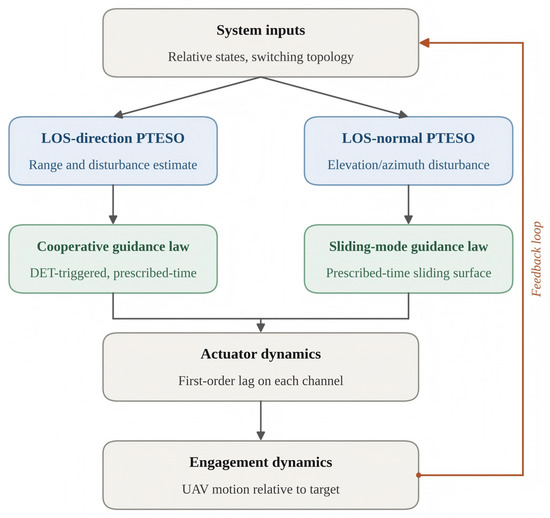
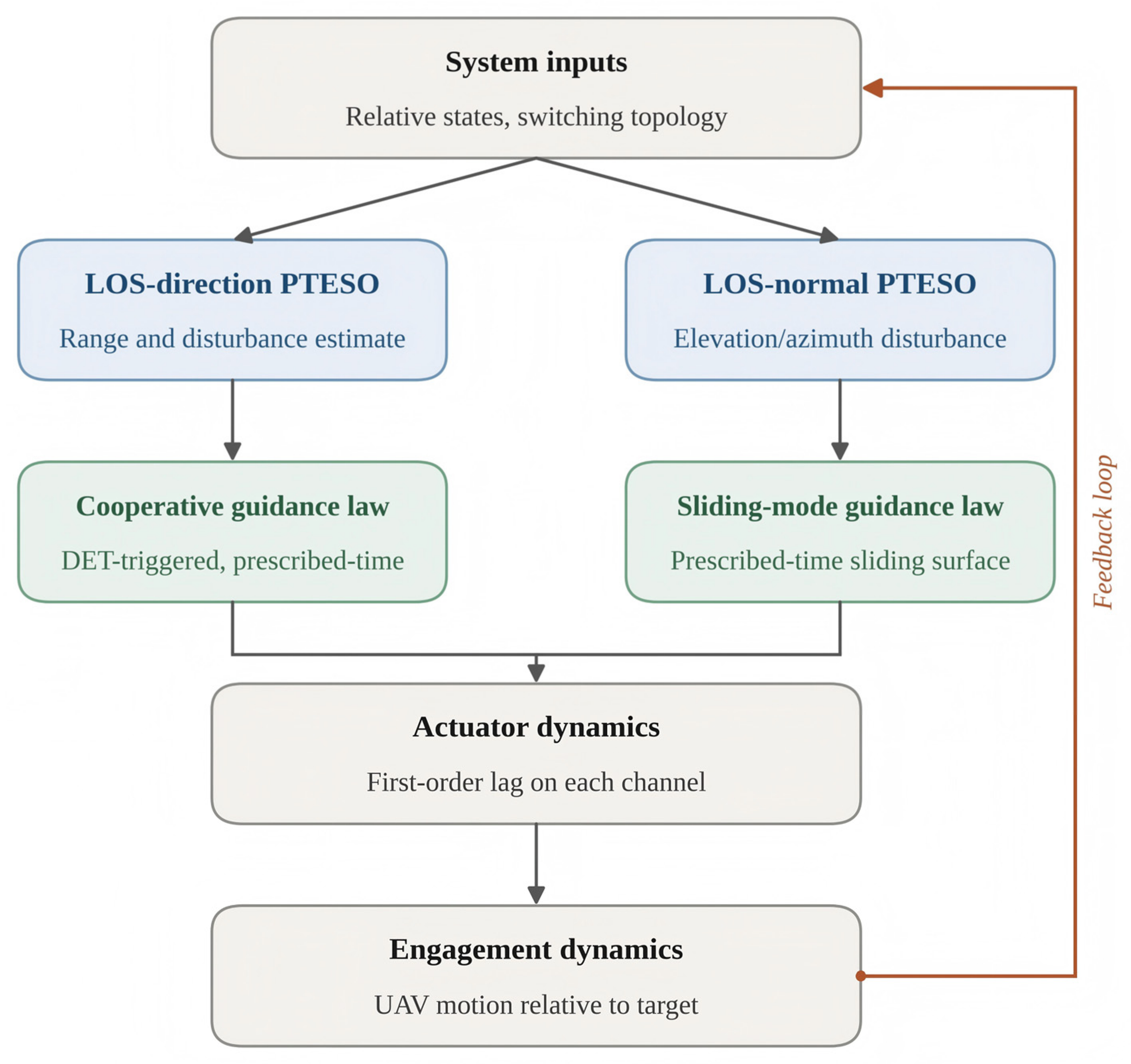
The overall architecture of the proposed three-channel prescribed-time cooperative guidance framework is illustrated in Figure 2, which summarizes how the LOS-direction and LOS-normal-direction PTESOs, the cooperative and sliding-mode guidance laws, the actuator dynamics, and the engagement dynamics are coupled through the feedback loop.
Figure 2.
Overall architecture of the proposed three-channel prescribed-time cooperative guidance framework.
Remark 3.
The specified arrival instant
and the prescribed consensus time are not free parameters; their choice must be compatible with the initial engagement geometry and the achievable maneuvering capability of each UAV. A necessary feasibility condition on is that it does not fall below the acceleration-limited minimum achievable engagement time of any UAV: solving for the smallest positive root gives the fastest time each UAV could reach the target under maximum closing acceleration, , and feasibility requires . Using the numerical scenario adopted later in the simulation study (Table 2, Section 5.1), this bound evaluates to approximately 12.4 s (UAV 1), well below the specified , confirming feasibility with margin. Separately, , where is the coasting (unguided) time-to-go, ensures the consensus time is reached before any UAV would passively reach the target with active guidance intervention absent.
Table 2.
Initial encounter conditions.
Consider the following radially unbounded Lyapunov function:
where . Based on Theorem 1, the LOS-direction prescribed-time cooperative guidance law is designed as
where is the NPTS reaching law defined by (25), with input given by the cooperation error and the time-varying parameter . is a constant gain, ensuring that the cooperation error converges exponentially and is strictly maintained once . At this point, the gain used inside in (40) and (41) is set to in place of the generic in (25), so that the reaching law remains valid for the worst-case topology and is uniformly valid for all candidate topologies.
To avoid a command jump caused by a hard switch between the NPTS law and the asymptotic constant-gain law near , a linearly weighted soft transition is introduced within the neighborhood of the switching instant in the simulation; that is, the LOS-direction reaching term in (40) is replaced by
where is a small positive constant.
To reduce the communication and actuation frequency, a dynamic event-triggered mechanism (DET) is introduced in the LOS direction: let the -th trigger instant be , with the held value updated as after triggering and being maintained unchanged over . The trigger condition is
where , is the ideal command value continuously computed according to (40) at the current state, and is the acceleration value actually held after the -th trigger. The threshold evolution law is
where is the initial threshold value, is the error-feedback gain, is the decay-rate term, and is a fixed lower bound for , avoiding the degeneration of the threshold to zero and thereby continuous triggering. In this triggering mechanism, the threshold evolves dynamically coupled with the trigger error , and the acceleration command is updated when the condition is satisfied, otherwise the previous instant’s output is maintained. in (43) denotes the algebraic connectivity of the currently active topology; in the proof of Theorem 3 below, the worst-case lower bound of the candidate topology set is used to conservatively estimate this quantity, ensuring the decay rate is uniformly valid at any switching instant.
In implementation, the candidate topology set is finite and known in advance, so the actual value of the currently active topology can be computed online and used directly in (43), yielding the tightest decay rate achievable at each instant. The worst-case bound is introduced only for the purpose of the stability guarantee in Theorem 3: since holds for all by definition (Section 2.1), any sufficient condition derived using —in particular the requirement in (46) and (47)—remains valid a fortiori under the actual online value, since . This substitution provides a conservative sufficient condition for the stability guarantee at every possible switching instant, while the implemented law itself uses the exact online value of .
Theorem 3.
For the LOS-direction system, when the PTESO convergence instant satisfies
, adopting the guidance law of (40) and (41) can ensure that the estimated arrival instants of the individual UAVs converge to consensus within the prescribed time and are strictly maintained thereafter for .
Proof.
From the above analysis, the actual acceleration is . From the trigger condition (42), between two consecutive triggers, . Substituting the actual actuated quantity into (30), by Theorem 2, when , the estimation error satisfies , where is given by (32) and is a known finite constant uniquely determined by . In the subsequent analysis, this residual term is treated as an additional Lipschitz-satisfying disturbance, and a sufficiently small parameter is chosen to ensure the composite Lyapunov function is negative definite. The treatment of and below differs because the two quantities are fundamentally different in nature, as explained next. By Theorem 2, is a known finite constant bounded by . whose magnitude can be reduced arbitrarily through the observer parameters ; it is accordingly absorbed into the negative-definite margin through a sufficiently small , in line with the standard treatment of a Lipschitz-bounded additive disturbance. The trigger error , by contrast, is a state-dependent quantity actively constrained in real time by the condition ; it cannot be reduced to a fixed constant and must instead be incorporated into the composite Lyapunov function , so that the decay of the threshold itself offsets its contribution. This yields
Combining the second term with Young’s inequality gives:
where , and is the uniform upper bound given by Assumption 2 (). Construct the composite Lyapunov function . When , taking the derivative of the Lyapunov function and substituting (43):
Choosing parameters such that , the above becomes
Choosing that is sufficiently small so that holds, and substituting into (47):
When :
Let ; by Lemma 1,
By Theorem 1, as , , i.e., converges to consensus.
When , is a fixed value and the trigger error still satisfies , the same Young’s-inequality decomposition applies with replaced by the constant , with the same conclusion, not repeated here. After switching to the constant-gain branch of (40), taking the derivative of :
Hence decreases exponentially and monotonically, and consensus is strictly maintained for . □
Theorem 4.
Under the dynamic event-triggered mechanism (42) and (43), the time interval between consecutive trigger instants
and has a positive lower bound, i.e.,
so that the number of triggers within any finite time interval is finite, and no Zeno behavior occurs.
Proof.
Let the -th trigger instant be , with the held value updated to for . Define the measurement error:
The trigger condition (42) is equivalent to holding throughout , until equality is reached and triggering occurs. By the expression of the guidance law (40), consists of the states and the observer estimate . Under the assumption of bounded trajectories of the closed-loop system , is Lipschitz continuous in time; let the Lipschitz constant be . A computable bound on can be obtained from the closed-loop trajectory. Differentiating with respect to time and applying the chain rule gives . Under Assumption 2 and the observer convergence established in Theorem 2, the following bounds hold along the trajectory: are bounded in terms of the sliding-surface parameters and the range lower bound ; , directly from the fourth equation of the observer in (24). Substituting these bounds together with the partial-derivative magnitudes of derived from (40) produces an explicit constant , which can be evaluated once the design parameters are fixed. While a fully expanded closed-form expression for can in principle be obtained by substituting the explicit partial derivatives of (40) and the trajectory bounds above, its length offers little additional insight; in practice, is evaluated numerically once are fixed, e.g., via symbolic differentiation of (40). Then:
The next trigger condition requires , i.e., . By the triangle inequality:
evolves according to (43) for , with its infimum being the fixed value for ; hence, for any , always holds, and taking this lower bound gives a trigger-interval lower bound independent of the initial condition.
When , , and , so . If , then by the time-continuity of , there exists such that the trigger condition is not satisfied over , so the trigger interval still has a positive lower bound. Hence, in the guidance law (40), , and so has a positive lower bound at the trigger instant. Since , then:
When , is constant and the guidance law switches to the constant-gain form, the Lipschitz continuity of in time still holds, and the derivation of the trigger condition, measurement-error estimate, and lower bound follows exactly the same structure as the stage, giving the same-form trigger-interval lower bound , not repeated here. □
4.2. LOS-Normal-Direction Cooperative Guidance Law Design
The LOS-normal-direction guidance law needs to drive the LOS elevation error and azimuth error to zero within the prescribed time , i.e., satisfying
Construct the prescribed-time sliding surfaces with time-varying gain:
where are constant gain coefficients in the sliding-surface design, and the time-varying function takes the piecewise form:
where is the time-varying gain coefficient, used to adjust the convergence rate of the sliding-surface gain.
Remark 4.
The sliding-surface gain
monotonically increases with time and tends to infinity as it approaches
, which is the key to ensuring that the elevation and azimuth angles can still converge in prescribed time on the sliding surface.
Remark 5.
The piecewise function
defined in (59) is continuous but not first-order differentiable at the three switching instants and , since jumps between terms of the form and zero at each boundary. This is addressed via saturation-based regularization: within a boundary layer of width around each switching instant, is clamped to its boundary value rather than diverging, so that itself remains bounded and continuous at every time instant (though not classically differentiable at the clamp boundary). In the proof of Theorem 5, the Lyapunov analysis is carried out separately on each interval where takes its unclamped or clamped form, and it is connected across switching instants through the continuity of itself rather than its derivative.
Taking the derivatives of and and substituting into the elevation- and azimuth-channel dynamics equations, respectively, gives:
where the feedforward compensation terms are, respectively,
Based on Theorem 1, the elevation-direction guidance law is designed as
where is the NPTS reaching law defined by (25), with input given by the sliding surface and time-varying parameter , where is the time-varying guarded countdown to ; is a constant gain. Once the sliding surface has converged for , the constant-gain law ensures its exponential stability, keeping it near zero thereafter. The azimuth direction has a fully symmetric structure, with its guidance law designed as
Theorem 5.
After PTESO convergence, adopting the guidance laws of (62) and (63) can ensure that the sliding surfaces
converge to zero within the prescribed time , and the LOS angle errors subsequently converge to zero within the prescribed time .
Proof.
Take the elevation channel as an example; the azimuth direction follows analogously. The proof proceeds in two parts.
Part 1: Prescribed-time convergence of the sliding surface. Construct the Lyapunov function and take its time derivative, substituting (25) and the elevation-direction guidance law (62). By Theorem 2, when , the estimation error satisfies ; choosing suitable makes , so after neglecting an arbitrarily small observation residual, when , let , so . Substituting gives:
By Theorem 1, as . When , the stage switches to the constant-gain branch of (62), and we have
Hence, converges exponentially and remains at zero thereafter.
Part 2: Convergence of the LOS angle error. Once the sliding surface has converged, , and from the sliding-surface definition (58):
Construct the Lyapunov function and take the derivative to obtain . When , let , so ; combining with Lemma 2 gives:
From (6), as , , so , i.e., . When , the sliding-surface constraint is now , so the system exponentially maintains stability. The azimuth direction follows analogously. This completes the proof of Theorem 5. □
4.3. Robustness Analysis Under Actuator Dynamics
Theorem 6.
After accounting for the first-order inertial actuator dynamics, if the rate of change of the commanded accelerations
is bounded, i.e., there exist constants
such that
hold for all
. Define the tracking deviations between the commanded and actual accelerations as
; then the three-channel tracking deviations are all uniformly ultimately bounded, i.e., there exists a finite instant
such that for
,
always holds.
Proof.
Take the range channel as an example. Taking the derivative of and substituting into the first-order inertial actuator equation:
Construct the Lyapunov function , and take the derivative:
When , , so converges into the compact set . The elevation- and azimuth-channel derivations follow exactly the same structure as the range channel; by the same reasoning, converges into the compact set , and converges into the compact set . □
Since the tracking deviation is uniformly bounded, it can be regarded as an additional disturbance satisfying the Lipschitz condition; choosing a sufficiently small robust-gain margin can absorb it into the original convergence compact set. Therefore, after introducing the first-order inertial actuator dynamics, the conclusions of prescribed-time convergence and cooperative consensus over the three channels still hold; the lower bound of convergence accuracy is jointly determined by the observation-error upper bound and the corresponding channel’s actuator-tracking-deviation upper bound. Actuator lag also affects the dynamic event-triggered mechanism: since the actual acceleration exhibits filtering delay relative to the ideal command, the convergence rate of the cooperation error is correspondingly slowed, the decay of the trigger error during the transient stage is delayed accordingly, and the trigger frequency rises slightly.
5. Simulation and Analysis
5.1. Simulation Setup and Comparative Results
It is worth emphasizing that the four-UAV maneuvering-target scenario adopted here follows a standard benchmark configuration widely used in the cooperative guidance literature (e.g., Refs. [9,38]) to quantitatively evaluate convergence accuracy, consensus performance, and communication efficiency; it is not intended to represent or optimize a weapon engagement. The same prescribed-time consensus and event-triggered framework applies directly to non-offensive tasks with identical mathematical structure, such as multiple UAVs synchronously arriving at a rescue site, multiple inspection UAVs converging on a moving structural-damage point for coordinated imaging, or multiple counter-UAS platforms cooperatively tracking and shepherding an unauthorized drone out of a protected airspace without any kinetic payload.
This paper conducts numerical simulations of four UAVs cooperatively approaching/tracking a maneuvering target to verify the effectiveness of the designed cooperative guidance law with prescribed-time convergence properties, together with its extended state observer and dynamic event-triggered mechanism. Considering the practical engineering realities that the UAV actuation mechanism exhibits response delay during flight and the inter-UAV communication link may vary with time, this paper further introduces first-order inertial actuator dynamics and switching communication topology in the simulation, in order to examine the robustness and applicability of the proposed method under conditions closer to engineering practice. To verify the superiority of the proposed guidance law, comparison simulations are also performed against [9,41] under identical initial conditions. Considering the limitations of the actuation mechanism, saturation and limiting are applied to the guidance command: the UAV acceleration magnitude does not exceed . The initial encounter conditions are shown in Table 2, with a numerical simulation step size of 0.01 s.
The inter-UAV communication topology switches periodically among the candidate set , corresponding respectively to sparse-ring, chain, and fully connected structures, with a switching period of and switching sequence cycling repeatedly. The adjacency matrices corresponding to the three topologies are, respectively,
The leader connection matrix is taken as . The guidance parameters selected in this paper are as follows:
The target’s initial position is , with velocity and acceleration
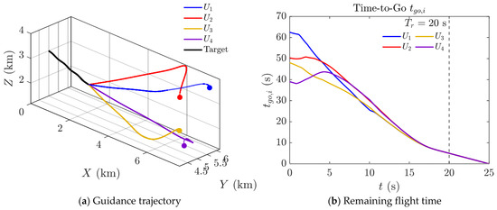
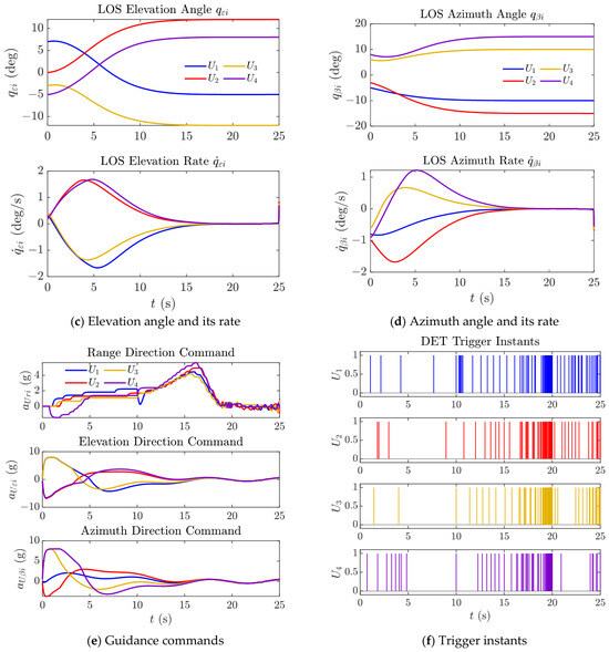
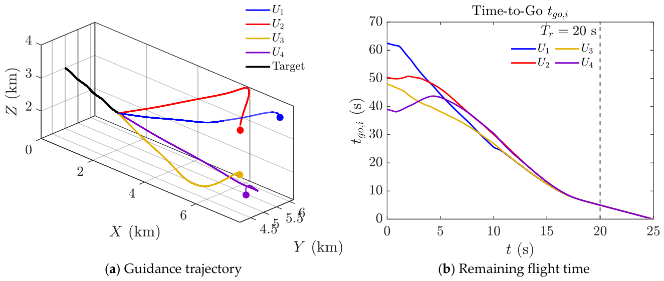
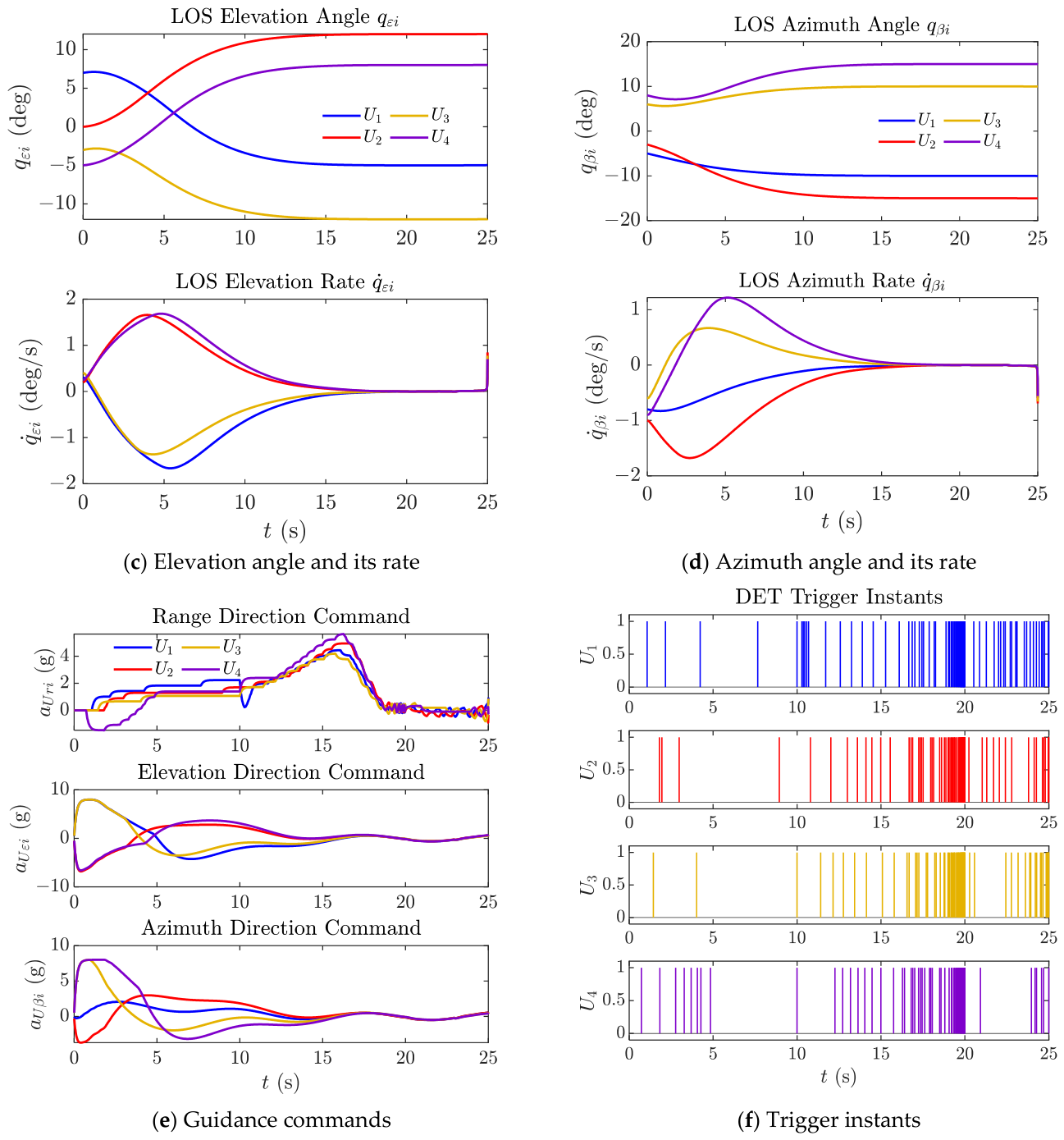
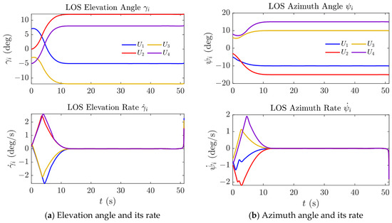
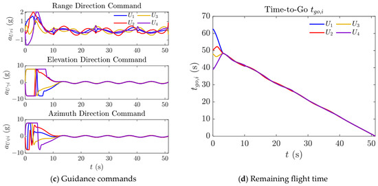
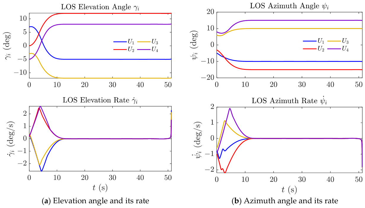
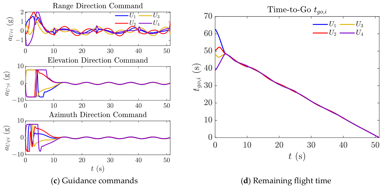
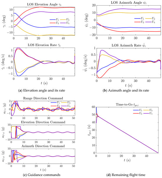
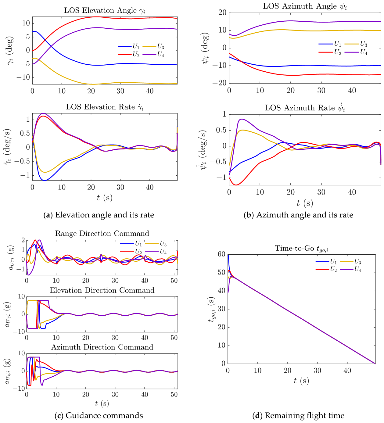
The simulation results of this paper’s method are shown in Table 3 and Figure 3. The results of the comparison methods are shown in Table 3 and Figure 4 and Figure 5.
Table 3.
Simulation results.
Figure 3.
Simulation results of the proposed guidance law.
Figure 4.
Simulation results of Ref. [41].
Figure 5.
Simulation results of Ref. [9].
Figure 3 presents the complete simulation results of the cooperative guidance law designed in this paper under the joint action of periodic candidate-topology switching and first-order inertial actuator dynamics. The initial separation of the four UAVs ranges from 6.8 to 7.8 km, with varying degrees of deviation between the initial LOS angles and the desired approach angle; among them, UAV 2’s elevation angle needs to turn from an initial 0° to the desired 12° and its azimuth angle from −3° to −15°, making it the UAV with the largest total angle adjustment among the four. The three-dimensional trajectories (Figure 3a) show that all four UAVs converge smoothly to the vicinity of the target in the terminal phase, with no evident abrupt maneuvers or high-frequency oscillation throughout. The remaining-flight-time curves (Figure 3b) exhibit considerable dispersion in the early stage of the simulation, gradually converging to consensus over time, essentially coinciding before the prescribed time , after which the four curves decrease approximately linearly and reach zero simultaneously at 25 s, corroborating the fact that all four UAVs’ arrival times in Table 3 equal 25.00 s. The LOS elevation- and azimuth-angle curves (Figure 3c,d) undergo a turning peak around the first 15 s of the simulation and subsequently converge monotonically to near the desired angle, consistent with the design objective of . The three-channel guidance commands (Figure 3e) never exceed the saturation limit throughout; the range-channel command briefly approaches the saturation boundary in the early simulation stage, thereafter gradually decaying to near zero, with the command curves overall smooth. In terms of the number of DET triggers, UAVs 1–4 trigger 91, 76, 83, and 75 times, respectively, during the 25 s cooperative rendezvous process, with a mean value of about 81.25. The trigger counts of UAV 1 and UAV 3 are generally somewhat higher than those of UAV 2 and UAV 4, consistent with the setting of the leader connection matrix —UAV 1 and UAV 3 communicate directly with the virtual leader UAV, so their cooperation error is simultaneously driven by both neighbor feedback and the leader time constraint, making the trigger condition relatively easier to activate, while UAV 2 and UAV 4 obtain time-cooperation information only indirectly through the topology, so their triggers are relatively sparse; nonetheless, the overall difference among the four UAVs is not large. Averaged over the whole process, each UAV triggers about 3.25 times per second, compared with the 2500 updates over the 25 s rendezvous process required for stepwise command updates at a fixed 0.01 s step size—a reduction in communication and actuation frequency of about 97%. This figure is computed relative to updates issued at every fixed 0.01 s numerical integration step, which does not necessarily represent an achievable or intended communication rate for an actual UAV datalink. The relative communication savings against a realistic baseline update rate—for example, 10–50 Hz, typical of tactical datalinks—would accordingly be smaller; nonetheless, the absolute mean inter-event interval of approximately 0.31 s, corresponding to roughly 3.25 triggers per second per UAV, remains a meaningful and hardware-relevant performance indicator. In terms of terminal accuracy, the miss distances of the four UAVs are 0.006 m, 0.007 m, 0.057 m, and 0.072 m (mean 0.036 m), respectively, with elevation angle errors within 0.033° (mean 0.033°) and azimuth angle errors within 0.030° (mean 0.028°). Comparing the proposed method with the two comparison methods under identical initial conditions, the three methods are not entirely equivalent at the level of cooperative-objective design. Ref. [41] is likewise a prescribed-time method, whose time-cooperation error can converge to zero within a designer-specified time. In the simulation, the four UAVs’ arrival times converge to 51.22–51.23 s, with good consistency and an inter-UAV deviation of about 0.01 s; however, what this method achieves is the mutual consensus of the remaining flight times of the individual UAVs—the guidance law itself does not introduce a target arrival instant directly specifiable by the designer, so the final common arrival instant is the result of the coupling between the initial encounter geometry and the internal algorithm dynamics, rather than a preset input quantity. Ref. [9] is a fixed-time method, whose convergence time only has a theoretical upper bound independent of the initial state, with the actual convergence speed still affected by internal gains; the four UAVs’ arrival times converge to 49.42 s, with similarly ideal consistency. The proposed method, by contrast, explicitly introduces the specified arrival instant into the guidance law; the arrival instants of all four UAVs are 25.00 s, exactly matching the preset , that is, while achieving prescribed-time convergence of time-cooperation consensus, it can also directly specify the final arrival instant to a value desired by the designer, an additional capability relative to the two comparison methods above. In terms of accuracy, the proposed method achieves a mean miss distance of 0.036 m, mean elevation error of 0.033°, and mean azimuth error of 0.028°. Ref. [41] achieves a mean miss distance of 0.223 m, with errors of 0.136° and 0.114°; Ref. [9] achieves a mean miss distance of 0.062 m, with errors of 0.137° and 0.132°. The proposed method clearly outperforms both comparison methods on both the miss-distance and angle-error metrics, reducing the miss distance by about 84% relative to Ref. [41] and by about 42% relative to Ref. [9]. As can be seen from Figure 4c, the range-channel and elevation-channel commands of the guidance law in Ref. [41] exhibit relatively pronounced high-frequency switching in the early simulation stage, repeatedly oscillating near the saturation boundary; such high-frequency components not only increase the burden on the actuation mechanism but may also partly explain its larger terminal angle error. In Figure 5, the command curves of Ref. [9]’s guidance law are relatively smooth, close to those of the proposed method, and its terminal accuracy is also markedly better than that of Ref. [41], indicating that the smoothing treatment of the reaching law has a direct impact on terminal accuracy.
Regarding real-time implementation, each UAV must, at every guidance cycle, update the three-state PTESO in (24), (27), and (28), evaluate the three-channel guidance law in (40), (62), and (63), and check the trigger condition in (42)—a computation of modest complexity (a small number of state updates and saturations per cycle). At the 0.01 s (100 Hz) step size used in this study, this computational load lies well within the capability of typical onboard flight-control processors, which commonly execute guidance and control loops at rates of 100–1000 Hz, suggesting that the proposed algorithm is computationally tractable for onboard deployment; hardware-in-the-loop verification is left for future work.
5.2. Robustness and Sensitivity Analysis
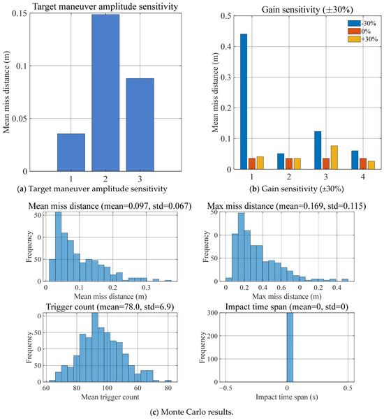
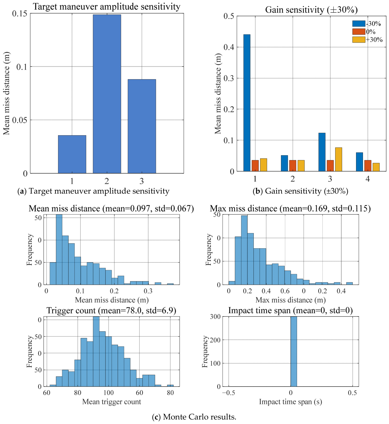
To assess robustness beyond the single deterministic scenario in Table 2, a Monte Carlo evaluation with independent trials was conducted. In each trial, the initial UAV–target ranges and closing velocities were perturbed by independent zero-mean Gaussian noise with 3% standard deviation, and the target maneuver amplitude in (71) was simultaneously scaled by an independent zero-mean Gaussian factor with 10% standard deviation. The resulting statistics were: mean miss distance , maximum miss distance , mean trigger count = 78.0 ± 6.9, and an impact-time span indistinguishable from zero at the 0.01 s temporal resolution of the threshold-based detector (mean = std = 0 s across all 300 trials; see Figure 6c), confirming that prescribed-time convergence and cooperative consensus are preserved under combined initial-condition and disturbance uncertainty.
Figure 6.
Monte Carlo and sensitivity analysis results.
Under a deterministic target-maneuver-amplitude sweep (scale factors of 1.0×, 1.5×, and 2.0× relative to the nominal profile in (71); see Figure 6a), the mean miss distance was 0.036 m, 0.149 m, and 0.088 m, respectively, with corresponding maxima of 0.072 m, 0.253 m, and 0.139 m. The dependence is not monotonic: because the guidance law enforces a prescribed convergence time independent of the disturbance magnitude, the realized miss distance is governed less by the raw amplitude of the target maneuver than by its phase relative to the finite-time convergence window, so an intermediate amplitude can transiently produce a larger tracking mismatch than a larger one. Importantly, across the entire tested range, the miss distance remains below 0.26 m, well within the accuracy tolerance required for the intended rendezvous/tracking tasks, indicating that the disturbance-observer-based compensation keeps the terminal accuracy bounded even as the target maneuver is substantially amplified.
A one-factor-at-a-time sensitivity analysis (±30% perturbation about the nominal value, Table 2 scenario) was performed on the four principal design gains (Table 4, Figure 6b). The closed-loop miss distance is most sensitive to : reducing it by 30% degrades the mean miss distance from 0.036 m to 0.441 m, while increasing it by 30% causes only a mild change (0.041 m), indicating that has a lower bound below which the range-channel convergence guarantee is compromised. The trigger-threshold error-feedback gain (Equation (43)) shows moderate asymmetric sensitivity (0.124 m at −30% versus 0.076 m at +30%), and shows mild, favorable sensitivity toward larger values (0.026 m at +30%, versus 0.060 m at −30%). Arrival-time deviation across all trials remained on the order of 10−4 s regardless of gain perturbation, confirming that the prescribed-time consensus mechanism is decoupled from these gain choices. These results indicate that should not be reduced substantially below its nominal value in practice, whereas the other three gains offer wider tuning margins.
Table 4.
One-factor-at-a-time gain sensitivity analysis results.
Tracking performance of the first-order actuator model was quantified via the RMSE and maximum deviation between commanded and actual acceleration. Across the four UAVs, tracking RMSE ranged from 0.071 g to 0.196 g, with maximum instantaneous lag deviations of 0.575–2.297 g (UAV1 and UAV4 exhibiting the largest transients, consistent with their comparatively larger initial engagement geometry). Despite these transients, closed-loop miss distance and terminal angle errors (below) remained within the required bounds, indicating that the disturbance-observer-based compensation adequately absorbs first-order actuator lag.
At impact, the mean absolute elevation and azimuth angle errors across the formation were 0.033° and 0.028°, respectively (individual UAV errors: elevation 0.032–0.033°, azimuth 0.024° to 0.030°), with an impact-time span indistinguishable from zero at the 0.01 s temporal resolution of the threshold-based detector (consistent with the common 25.00 s arrival time reported for all four UAVs in Table 3) and a mean trigger count of 81.25 per UAV. These results confirm simultaneous, terminal-angle-constrained impact with sub-0.04° angular accuracy across all engagement geometries.
6. Conclusions
Addressing the engineering problem of time-varying communication topology coexisting with actuator response delay in multi-UAV cooperative tracking and rendezvous with maneuvering targets, this paper has proposed a three-dimensional cooperative control method integrating a prescribed-time extended state observer, a prescribed-time cooperative guidance law, and a dynamic event-triggered mechanism. Theoretical analysis shows that the disturbance estimation error, the remaining-flight-time consensus error, and the LOS angle error can all converge within a designer-specified time, with the convergence instant independent of the initial system state; the dynamic event-triggered mechanism has a positive trigger-interval lower bound independent of the initial condition under arbitrary switching of candidate topologies, with no Zeno behavior. After accounting for the first-order inertial dynamics of the autopilot, the command tracking error remains uniformly ultimately bounded, and the prescribed-time convergence properties are still preserved. Numerical simulations have verified the above theoretical results; compared with existing fixed-time and prescribed-time cooperative guidance methods, the proposed method shows a clear improvement in terminal accuracy and convergence properties. Nevertheless, the proposed method still has certain limitations: the terminal accuracy is relatively sensitive to the initial LOS-angle deviation; the compact-set radius is not entirely independent of the initial state; and validation has only been carried out for undirected connected topologies, without considering directed topologies and communication delay. The switching-topology robustness established in Theorem 3 further presupposes that each candidate topology in remains connected at all times; it does not extend to robustness against unplanned link or node failures that could disconnect the communication graph, nor does it account for UAV endurance and range limits or return-to-base feasibility, all of which are practical operational constraints left for future investigation. Future work will focus on early-stage feedforward compensation, adaptive tuning of the trigger gain, and cooperative guidance under directed switching topologies, as well as extension to varying team sizes.
Author Contributions
Conceptualization, F.Y., J.Y. and H.Y.; methodology, F.Y., J.Y. and H.Y.; software, F.Y.; validation, F.Y. and L.Z.; formal analysis, F.Y., J.Y., H.Y. and L.S.; investigation, F.Y.; resources, F.Y., J.Y. and H.Y.; data curation, F.Y. and J.Y.; writing—original draft preparation, F.Y.; writing—review and editing, J.Y. and H.Y.; visualization, F.Y. and L.Z.; supervision, J.Y. and H.Y.; project administration, L.S.; funding acquisition, L.S. All authors have read and agreed to the published version of the manuscript.
Funding
This research was funded by the National Natural Science Foundation of China grant number 62173339, and the APC was funded by L.S.
Data Availability Statement
The data presented in this study are available on request from the corresponding author.
DURC Statement
Current research is limited to prescribed-time cooperative control and event-triggered guidance theory for multi-UAV systems, which is beneficial for non-offensive applications such as cooperative search-and-rescue, coordinated low-altitude airspace security, and time-synchronized logistics delivery and does not pose a threat to public health or national security. The authors acknowledge the dual-use potential of the research involving guidance-law theory with historical roots in missile guidance, and we confirm that all necessary precautions have been taken to prevent potential misuse—this manuscript’s contribution is limited to generic control-theoretic results (a prescribed-time extended state observer, a switching-topology-robust consensus protocol, and an event-triggered communication scheme) containing no weapon-specific, classified, or export-controlled information. As an ethical responsibility, the authors strictly adhere to relevant national and international laws about DURC. The authors advocate for responsible deployment, ethical considerations, regulatory compliance, and transparent reporting to mitigate misuse risks and foster beneficial outcomes.
Conflicts of Interest
The authors declare no conflicts of interest.
References
- Jeon, I.S.; Lee, J.I.; Tahk, M.J. Homing guidance law for cooperative attack of multiple missiles. J. Guid. Control Dyn. 2010, 33, 275–280. [Google Scholar] [CrossRef] [Scilit]
- Jeon, I.S.; Lee, J.I.; Tahk, M.J. Impact-time-control guidance law for anti-ship missiles. IEEE Trans. Control Syst. Technol. 2006, 14, 260–266. [Google Scholar] [CrossRef] [Scilit]
- Kim, M.; Grider, K.V. Terminal guidance for impact attitude angle constrained flight trajectories. IEEE Trans. Aerosp. Electron. Syst. 1973, 9, 852–859. [Google Scholar] [CrossRef] [Scilit]
- Lee, C.H.; Kim, T.H.; Tahk, M.J. Interception angle control guidance using proportional navigation with error feedback. J. Guid. Control Dyn. 2013, 36, 1556–1561. [Google Scholar] [CrossRef] [Scilit]
- Feng, Y.; Yu, X.; Man, Z. Non-singular terminal sliding mode control of rigid manipulators. Automatica 2002, 38, 2159–2167. [Google Scholar] [CrossRef] [Scilit]
- Wang, C.; Yu, H.; Dong, W.; Wang, J. Three-dimensional impact angle and time control guidance law based on two-stage strategy. IEEE Trans. Aerosp. Electron. Syst. 2022, 58, 5361–5372. [Google Scholar] [CrossRef] [Scilit]
- Xie, J.; Ma, K. Suboptimal guidance law against maneuvering target with time and angle constraints. Aerosp. Sci. Technol. 2024, 148, 109111. [Google Scholar] [CrossRef] [Scilit]
- Gong, M.; Zhou, S.; Zhou, D. Optimal sliding mode guidance law against maneuvering target with impact angle constraint. Proc. Inst. Mech. Eng. Part G 2024, 238, 513–528. [Google Scholar] [CrossRef] [Scilit]
- Dong, W.; Wang, C.; Wang, J.; Zuo, Z.; Shan, J. Fixed-time terminal angle-constrained cooperative guidance law against maneuvering target. IEEE Trans. Aerosp. Electron. Syst. 2022, 58, 1352–1366. [Google Scholar] [CrossRef] [Scilit]
- Chen, Z.; Chen, W.; Liu, X.; Cheng, J. Three-dimensional fixed-time robust cooperative guidance law for simultaneous attack with impact angle constraint. Aerosp. Sci. Technol. 2021, 110, 106523. [Google Scholar] [CrossRef] [Scilit]
- Polyakov, A. Nonlinear feedback design for fixed-time stabilization of linear control systems. IEEE Trans. Autom. Control 2012, 57, 2106–2110. [Google Scholar] [CrossRef] [Scilit]
- Song, Y.; Wang, Y.; Holloway, J.; Krstic, M. Time-varying feedback for regulation of normal-form nonlinear systems in prescribed finite time. Automatica 2017, 83, 243–251. [Google Scholar] [CrossRef] [Scilit]
- Sánchez-Torres, J.D.; Gómez-Gutiérrez, D.; López, E.; Loukianov, A.G. A class of predefined-time stable dynamical systems. IMA J. Math. Control Inf. 2018, 35, i1–i29. [Google Scholar] [CrossRef] [Scilit]
- Jiménez-Rodríguez, E.; Muñoz-Vázquez, A.J.; Sánchez-Torres, J.D.; Defoort, M.; Loukianov, A.G. A Lyapunov-like characterization of predefined-time stability. IEEE Trans. Autom. Control 2020, 65, 4922–4927. [Google Scholar] [CrossRef] [Scilit]
- Bhat, S.P.; Bernstein, D.S. Finite-time stability of continuous autonomous systems. SIAM J. Control Optim. 2000, 38, 751–766. [Google Scholar] [CrossRef] [Scilit]
- Hu, Z.; Liang, X.; Yi, W. A generalized super-twisting extended state observer for angle-constrained terminal sliding mode guidance law. Aerospace 2025, 12, 252. [Google Scholar] [CrossRef] [Scilit]
- He, Y.; Guo, F.; Zhang, H.; Chen, S. Pre-defined time convergent non-singular terminal sliding mode guidance law with impact angle constraint. Proc. Inst. Mech. Eng. Part G. 2025, 239, 2482–2495. [Google Scholar] [CrossRef] [Scilit]
- Yi, X.; Wang, C.; Dong, W.; Deng, F. Observation-shared cooperative look-angle tracking guidance for multiple missiles with partial seekers. IEEE Trans. Aerosp. Electron. Syst. 2025, 61, 11586–11599. [Google Scholar] [CrossRef] [Scilit]
- Ma, W.; Liu, S.; Huang, W. Robust prescribed-time observer-based sliding mode control: Theoretical design and flight control applications. ISA Trans. 2025, 167, 1446–1457. [Google Scholar] [CrossRef] [Scilit] [PubMed]
- Olfati-Saber, R.; Murray, R.M. Consensus problems in networks of agents with switching topology and time-delays. IEEE Trans. Autom. Control 2004, 49, 1520–1533. [Google Scholar] [CrossRef] [Scilit]
- Ning, B.; Jin, J.; Zheng, J. Fixed-time consensus for multi-agent systems with discontinuous inherent dynamics over switching topology. Int. J. Syst. Sci. 2017, 48, 2023–2032. [Google Scholar] [CrossRef] [Scilit]
- Li, Z.; Wen, G.; Duan, Z.; Ren, W. Designing fully distributed consensus protocols for linear multi-agent systems with directed graphs. IEEE Trans. Autom. Control 2014, 60, 1152–1157. [Google Scholar] [CrossRef] [Scilit]
- Sinha, A.; Kumar, S.R. Cooperative target capture using predefined-time consensus over fixed and switching networks. Aerosp. Sci. Technol. 2022, 127, 107686. [Google Scholar] [CrossRef] [Scilit]
- Hou, Z.; Lan, X.; Chen, H.; Zhuang, X. Finite-time cooperative guidance law for multiple missiles with impact angle constraints and switching communication topologies. J. Intell. Robot. Syst. 2023, 108, 85. [Google Scholar] [CrossRef] [Scilit]
- Ma, X.; Tan, Y.; Mei, H. Predefined-time consensus of nonlinear multi-agent input delay/dynamic event-triggered under switching topology. IEEE Access 2023, 11, 29883–29895. [Google Scholar] [CrossRef] [Scilit]
- Qin, M.; Wang, L.; Xi, J.; Wang, C.; Luo, S. Bounded-gain prescribed-time robust spatiotemporal cooperative guidance law for UAVs under jointly strongly connected topologies. Drones 2025, 9, 474. [Google Scholar] [CrossRef] [Scilit]
- Ma, W.; Guo, X. Prescribed-time cooperative guidance law for multi-UAV with intermittent communication. Drones 2024, 8, 748. [Google Scholar] [CrossRef] [Scilit]
- Xu, J.Z.; Liu, Z.W.; Ge, M.F.; Yang, T.; Chi, M.; He, D. Distributed predefined-time algorithms for optimal solution seeking in multi-agent systems subject to input disturbances. Automatica 2025, 174, 112139. [Google Scholar] [CrossRef] [Scilit]
- Ma, W.; Fang, Y.; Fu, W.; Liang, X. Three-dimensional prescribed-time impulsive pinning cooperative guidance. Int. J. Aeronaut. Space Sci. 2023, 24, 1375–1388. [Google Scholar] [CrossRef] [Scilit]
- Tabuada, P. Event-triggered real-time scheduling of stabilizing control tasks. IEEE Trans. Autom. Control 2007, 52, 1680–1685. [Google Scholar] [CrossRef] [Scilit]
- Girard, A. Dynamic triggering mechanisms for event-triggered control. IEEE Trans. Autom. Control 2014, 60, 1992–1997. [Google Scholar] [CrossRef] [Scilit]
- Ning, P.; Hua, C.; Li, K.; Meng, R. Event-triggered control for nonlinear uncertain systems via a prescribed-time approach. IEEE Trans. Autom. Control 2023, 68, 6975–6981. [Google Scholar] [CrossRef] [Scilit]
- Ning, P.; Hua, C.; Li, K.; Meng, R. Event-triggered adaptive prescribed-time control for nonlinear systems with uncertain time-varying parameters. Automatica 2023, 157, 111229. [Google Scholar] [CrossRef] [Scilit]
- Zhang, K.; Hu, Z.; Song, F.; Yang, X.; Liu, Y. Consensus of input constrained multi-agent systems by dynamic time-varying event-triggered strategy with a designable minimal inter-event time. IEEE Trans. Circuits Syst. II 2023, 71, 2119–2123. [Google Scholar] [CrossRef] [Scilit]
- Zhai, J.; Yang, J. An event-triggered distributed cooperative guidance law for simultaneous attack with autopilot lag consideration. Trans. Inst. Meas. Control 2023, 45, 2043–2058. [Google Scholar] [CrossRef] [Scilit]
- Zhang, D.; Yu, H.; Dai, K.; Yi, W.; Zhang, H.; Guan, J.; Yuan, S. Three-dimensional event-triggered predefined-time cooperative guidance law. Aerospace 2024, 11, 999. [Google Scholar] [CrossRef] [Scilit]
- Li, G.; Zhong, Q.; Zuo, Z.; Wu, Y.; Lü, J. Performance prescribed cooperative guidance against maneuvering target under malicious attacks. IEEE Trans. Syst. Man Cybern. Syst. 2024, 54, 7770–7782. [Google Scholar] [CrossRef] [Scilit]
- Zhu, H.; Wen, G.; Wang, L.; Lu, J. Impact-angle-constrained cooperative guidance: An event-triggered finite-time strategy. IEEE Trans. Aerosp. Electron. Syst. 2025, 61, 10038–10049. [Google Scholar] [CrossRef] [Scilit]
- Xu, C.; Wang, Y.; Niu, Z.; Luo, S.; Du, F. Fixed-time convergent guidance law with angle constraint and autopilot lag compensation using partial-state feedback. Aerospace 2023, 10, 964. [Google Scholar] [CrossRef] [Scilit]
- Zhao, K.; Song, J.; Yu, J.; Liu, Y. Cooperative guidance under multiple constraints without active speed control. Aerosp. Sci. Technol. 2025, 164, 110446. [Google Scholar] [CrossRef] [Scilit]
- Zhang, L.; Li, D.; Jing, L.; Ju, X.; Cui, N. Appointed-time cooperative guidance law with line-of-sight angle constraint and time-to-go control. IEEE Trans. Aerosp. Electron. Syst. 2023, 59, 3142–3155. [Google Scholar] [CrossRef] [Scilit]

Disclaimer/Publisher’s Note: The statements, opinions and data contained in all publications are solely those of the individual author(s) and contributor(s) and not of MDPI and/or the editor(s). MDPI and/or the editor(s) disclaim responsibility for any injury to people or property resulting from any ideas, methods, instructions or products referred to in the content. |
© 2026 by the authors. Licensee MDPI, Basel, Switzerland. This article is an open access article distributed under the terms and conditions of the Creative Commons Attribution (CC BY) license.