


Highlights
What are the main findings?
- Tube Reconstruction Mechanism: The elastic tube adaptively shifts its boundaries to avoid dynamic obstacles, maintaining global path connectivity and preventing trajectory interruptions in complex environments. By linearizing constraints within local sub-tubes, this mechanism integrates seamlessly with the DMPC framework, significantly enhancing onboard computational efficiency.
- Risk-Aware Collision Avoidance: Incorporating position error models for enhanced safety, this strategy activates collision constraints only upon detecting potential risks, effectively resolving the solution space collapse common in traditional methods. This on-demand activation logic drastically reduces the computational load on the controller, ensuring real-time solving performance even in high-density UAV swarm scenarios.
What are the implications of the main findings?
- A Resilient Technical Foundation for Urban Air Mobility Infrastructure. The proposed dynamic tube framework serves as a resilient digital air highway, capable of automatically adapting to urban environmental shifts such as construction or sudden airspace restrictions.
- Enabling Practical Deployment on Resource-Constrained Systems. The research demonstrates that advanced distributed control algorithms can run efficiently on embedded onboard platforms of lightweight UAVs without relying on expensive ground-based computing.
Abstract
Navigating large-scale Unmanned Aerial Vehicle (UAV) swarms through restricted airspaces requires a delicate balance between rigorous safety guarantees and high mission throughput. To address the limitations of rigid tube structures and over-constrained optimization problems, we present a Dynamic Tube-based Distributed Model Predictive Control (DMPC) approach. Unlike traditional methods, our framework introduces an elastic tube reconstruction mechanism that adaptively shifts boundaries to accommodate dynamic obstacles while maintaining a connected navigable tube. By integrating a predictive risk-triggered constraint activation policy, the proposed controller avoids the curse of over-conservativeness, ensuring recursive feasibility in high-density scenarios. Quantitative results indicate that our method reduces redundant computations while maximizing workspace utilization, providing a scalable solution for future Urban Air Mobility infrastructures (UAM).
1. Introduction
With the burgeoning development of the low-altitude economy and Urban Air Mobility (UAM), Unmanned Aerial Vehicle (UAV) swarms are increasingly deployed in diverse applications, ranging from urban inspection and logistics delivery to emergency search and rescue operations [1,2,3]. To ensure flight safety and maintain traffic order within complex urban environments, constraining UAVs to fly within predefined virtual corridors or tubes has emerged as a mainstream trend in air traffic management [4]. These virtual tubes function as aerial lanes analogous to ground roadways, effectively partitioning flight zones by integrating global paths with real-time local information. This mechanism isolates flights from building complexes and obstacles, thereby efficiently guiding large-scale swarms [5,6].
Regarding the theoretical construction of virtual tubes, research led by Professor Quan’s team has utilized distributed vector field methods to develop various geometries, including linear [7], curved [8], and circular [9] tubes, with a primary focus on designing controllers that ensure stable swarm passage within static, preset environments. Building upon these foundations, researchers further introduced the connected quadrangle virtual tube construction theory [10]. This approach deconstructs complex flight airspace into a series of interconnected trapezoidal safety regions, enabling swarms to navigate smoothly through highly constrained spaces such as narrow corridors, window frames, or gantries.
While the aforementioned studies demonstrate exceptional performance in static environments or specific mission profiles, they encounter significant limitations when applied to the evolving landscape of urban air traffic. Recent progress has been made in online tube generation [11] and rapid replanning methods [12] tailored for sudden environmental shifts, such as fire emergencies. These studies largely emphasize an on-demand generation logic, treating the tube as a dynamic ensemble of trajectories that adjust according to environmental pressures. This mechanism exhibits high flexibility for isolated emergency tasks or low-density obstacle avoidance. However, as UAM evolves toward high-frequency and large-scale operations, the role of virtual tubes must transition from single-mission guidance to long-term operational frameworks [13,14]. In this context, virtual tubes should possess attributes of long-term existence and persistent maintenance, serving as digital skyway infrastructures that sustain global traffic flow order.
How to efficiently coordinate large-scale swarms and resolve conflicts within virtual tubes is one of the essential requirements for ensuring safe airspace accessibility. Distributed Model Predictive Control (DMPC) has become the preferred methodology for intra-tube planning due to its unique spatiotemporal foresight and its inherent capacity to handle multi-variate constraints [15,16]. Compared to traditional reactive planning, DMPC leverages a receding horizon optimization mechanism to identify potential conflicts based on the predicted spatiotemporal trajectories of neighboring agents. It globally orchestrates the current control law and future states within a finite prediction window [17,18]. Simultaneously, DMPC preserves the real-time autonomous decision-making capability of individual agents while achieving distributed coordination through explicit information exchange, such as the sharing of predicted trajectories [19].
However, while DMPC provides a rigorous mathematical framework for trajectory planning, its practical efficacy depends heavily on the design of obstacle avoidance constraints. Conventional avoidance designs predominantly utilize spatial partitioning techniques such as potential functions [20,21], Buffered Voronoi Cells (BVC) [22,23], or safe flight corridors [24,25]. These methods typically adopt an always-on constraint strategy. However, in the spatially restricted environments of virtual tubes, high UAV density often leads to these conservative strategies excessively compressing the feasible region of the optimization problem, ultimately triggering feasible space collapse. To mitigate this bottleneck, researchers have begun exploring more flexible avoidance activation mechanisms to strike a balance between safety and feasibility. For instance, DMPC frameworks integrated with event-triggered mechanisms [26] or on-demand collision avoidance strategies [27,28] have been proposed, where constraints are dynamically activated only when a collision risk is detected within the prediction window. Furthermore, to alleviate pressure on the solution space, enhanced schemes such as relative safe flight corridors [29] and BVCs with warning bands [30] have been developed. These methods utilize dynamic hyperplane patching rather than global path reconstruction to maintain the recursive feasibility of the optimization process.
Nevertheless, in UAM scenarios, obstacle avoidance activation mechanisms cannot guarantee the order of large-scale traffic flows if detached from a stable route structure. Addressing this, we propose a distributed planning framework under persistent virtual tube constraints. This framework treats the virtual tube as long-term digital infrastructure, ensuring the orderliness of global traffic flow. Compared with existing literature, the main contributions of this paper are as follows:
- A dynamic tube update mechanism with persistent maintenance characteristics. Targeting the intrusion of dynamic obstacles, we propose a real-time boundary correction strategy based on an elastic model. This strategy isolates environmental obstacles while ensuring that the global route does not suffer from fractures or large-scale deviations due to temporary disturbances, thereby maintaining the structural continuity of the route as infrastructure.
- A risk-driven on-demand collision avoidance strategy. We introduce a spatiotemporal partitioning method based on trajectory and collision risk. Addressing the issue of solution space compression caused by tube boundaries, this method activates safety constraints on-demand only when potential conflicts are detected. By eliminating redundant constraints, computational overhead is significantly reduced.
- An integrated distributed predictive control scheme for tube constraints and conflict resolution. We construct and validate a DMPC collaborative planning framework covering the full task cycle. The proposed architecture allows individual UAVs to independently optimize control strategies while strictly adhering to boundary safety and inter-agent collision avoidance. Numerical simulations and hardware experiments verify the robustness and recursive feasibility of the algorithm in virtual tube traversal tasks.
The remainder of this paper is organized as follows. Section 2 defines the cooperative planning problem for swarms within persistent virtual tubes, establishing the mathematical descriptions for the virtual tube, UAV dynamics, and multi-agent safety criteria. Section 3 elaborates on the proposed distributed collaborative planning framework, focusing on the collision avoidance strategy and virtual tube maintenance. Section 4 validates the recursive feasibility and robustness of the proposed method through simulation and hardware experiments. Finally, Section 5 concludes the paper and outlines potential directions for future research.
2. Preliminaries
2.1. Robot Model
To address the collaborative trajectory planning problem within the virtual tube, it is essential to model the mobility characteristics of individual UAVs. Consider a swarm of M agents, where each agent is modeled as a rigid body in (). To focus on the high-level coordination algorithm design, the dynamics of each agent i is described by a discrete-time double integrator model:
Let denote the position, velocity, and acceleration (control input) of agent i at time t, respectively. Given a sampling time step h and defining the state vector as , the discrete-time state transition from t to can be expressed in a compact form:
where and denote the identity and zero matrices. The constant system matrices and are given by:
To ensure that the UAV states remain within physical limits and that the resulting trajectories are feasible, the following constraints on velocity and acceleration are imposed:
where and are predefined symmetric positive-definite weighting matrices that characterize the directional importance for velocity and acceleration, respectively. The scalars and denote the maximum allowable limits. This kinematic model serves as the foundation for prediction and optimization within the subsequent DMPC framework.
2.2. Collision Avoidance
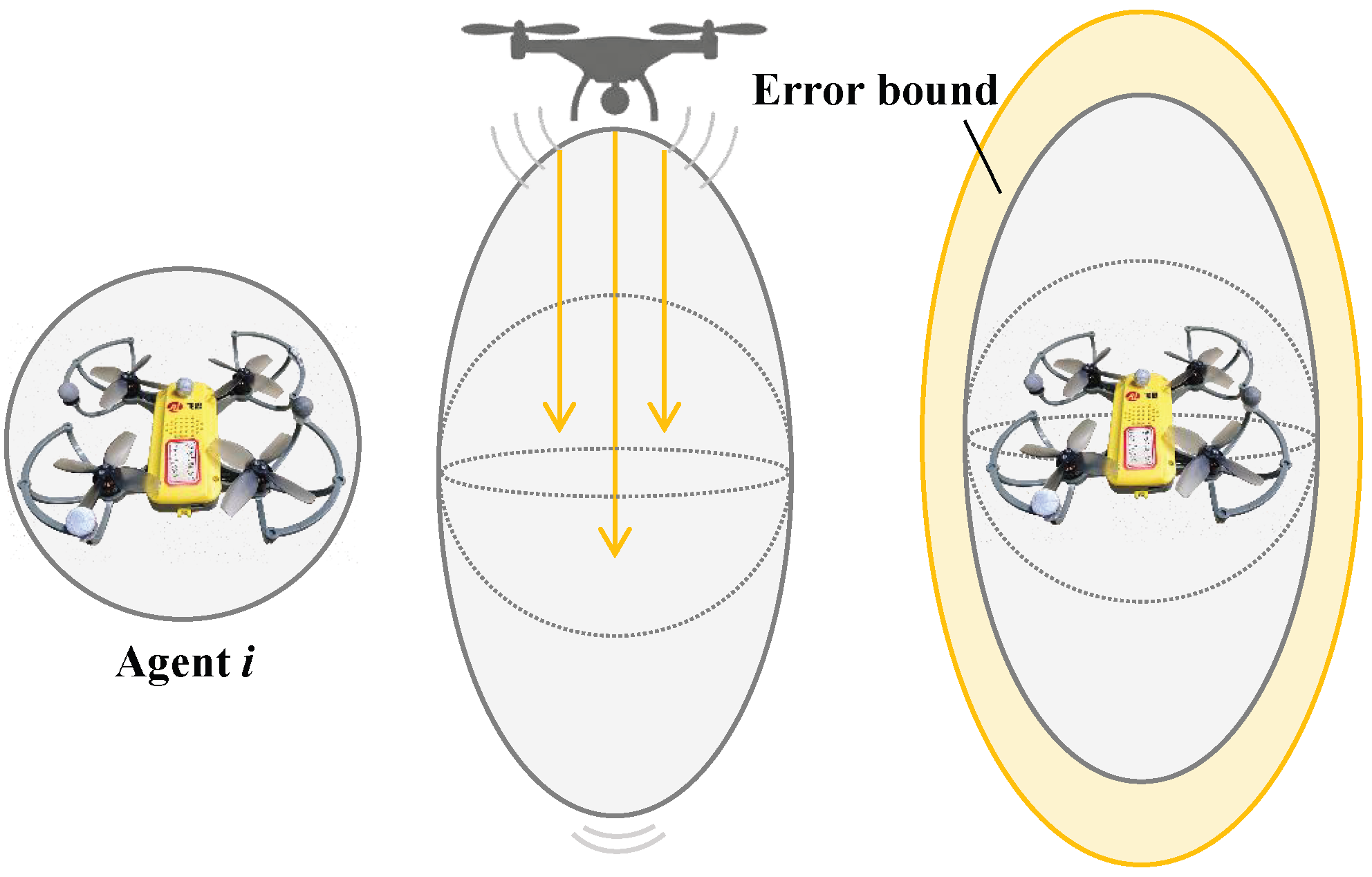
To ensure the safe flight of a UAV swarm, collision avoidance constraints must be strictly defined. The physical occupancy model of a UAV depends on its geometric configuration. For multi-rotor platforms, each UAV can be modeled as a spherical rigid body, with an impenetrable safety physical collision radius defined as . Additionally, the downwash airflow generated by neighboring UAVs can significantly affect flight stability or even lead to loss of control [31]. In this paper, the downwash effect is modeled as an ellipsoid elongated along the vertical direction. Specifically, for any pair with , the deterministic safety condition between the centers of agent i and j is defined as the following formula:
where is the scaling matrix, and is the minimum safety distance in the horizontal direction. According to [28], we define , indicating that the required safety distance in the vertical direction is times that of the horizontal direction. For other flight platforms, such as fixed wing swarms, the primary physical risk stems from wake turbulence generated by wingtip vortices. In such scenarios, the scaling matrix can be reconfigured as anisotropic ellipsoids or conical keep out zones to adapt to different aerodynamic characteristics, involving only updates to the constraint geometry.
Furthermore, considering the localization uncertainty in real-world environments, we introduce probabilistic safety guaranties. Assuming the localization error follows a zero mean Gaussian distribution , and drawing on the relevant probabilistic collision avoidance framework [32], we require the following probabilistic constraint to be satisfied:
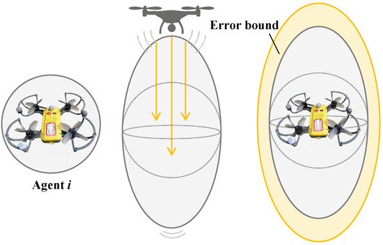
where is the user specified collision probability threshold. By transforming the chance constraint into a deterministic buffer, we can equate the localization uncertainty to an additional safety margin , such that in the aforementioned formula is replaced by . As shown in Figure 1, the final collision avoidance model formulated under spatial position uncertainty is unified into the following form:
where the relationship between and the covariance as well as the probability threshold is defined as .
Figure 1.
UAV collision models. (Left) Physical rigid body representation. (Middle) Model with downwash effect compensation. (Right) Robust safety region under spatial position uncertainty.
2.3. Virtual Tube Model
The virtual tube is a spatial infrastructure designed to provide a continuous safe region for UAV swarm navigation. It defines the admissible flight volume and boundary constraints based on a predefined reference path.
The foundation of the virtual tube is a reference centerline , which can be represented as a continuously differentiable curve fitted from a sequence of discrete waypoints . For any reference point , a local Frenet-Serret frame is established to define the tube’s spatial orientation. Within this frame, denotes the unit tangent vector, and the orientation is further constrained by the unit normal vector , representing the orthogonal direction within the navigation plane [8].
The admissible flight area is constructed by sweeping a cross-sectional geometry along the centerline. At each reference point l, the cross-section is defined as the set of:
To account for the physical dimensions and ensure collision-free navigation, the effective tube radius is derived from the environmental safety margin R and the safety radius . The formulation is refined as to maintain geometric consistency within the constrained space. Here, the upper bound restricts the trajectory of the agent center to ensure the entire safety envelope remains within the tube. Simultaneously, the lower bound serves as a feasibility constraint by preserving the minimum navigable space for at least one UAV in congested environments.
2.4. Problem Formulation
For a swarm consisting of M agents, the mission is to navigate through a persistent virtual tube . The objective is to design a distributed control strategy that simultaneously satisfies two critical requirements: (i) Each agent’s trajectory remains strictly within the tube region . (ii) No inter-agent collisions occur.
Following the DMPC frameworks established in [27,28], each agent independently solves a K-step predictive control problem at each sampling time in a receding horizon fashion. The prediction horizon K is a critical parameter for balancing computational efficiency and motion safety. To provide a rigorous theoretical guarantee for the recursive feasibility of the DMPC optimization, K must satisfy the kinematic braking constraint , where denotes the maximum velocity, represents the maximum deceleration, and h is the sampling interval [30]. This constraint ensures that the prediction horizon K provides a sufficient time horizon for an agent to decelerate from its maximum speed to a complete stop. By maintaining this lookahead horizon, the framework guarantees the existence of at least one feasible braking trajectory even in worst-case scenarios. This prevents violations of tube boundaries or inter-agent collisions, while ensuring that the optimization remains solvable throughout the navigation process.
Problem 1 (Distributed Tube Traversal Optimization): At each time step t, each agent i solves the following constrained optimization problem over the prediction horizon :
Upon obtaining the optimal control sequence , only the first control input is applied during the interval following the receding horizon principle. At the subsequent sampling instance , each agent independently updates its state via sensor feedback and solves its local optimization problem in parallel, utilizing locally perceived tube constraints and neighbors’ predicted trajectories obtained through inter-agent communication. Under this distributed architecture, the tube constraint serves as a persistent spatial infrastructure guiding the navigation. Each agent iteratively executes a closed-loop sequence of optimization, tracking, and update. This real-time receding horizon mechanism empowers the swarm to robustly adapt to environmental disturbances, ensuring that all agents traverse the virtual tube and reach their objectives with high fidelity.
3. Optimization Framework
This section details the proposed DMPC framework. The framework first establishes the foundation for state evolution through a discrete-time linear predictive model. Subsequently, a risk-aware mechanism dynamically triggers inter-agent collision avoidance constraints. Combined with tube reconstruction and linearization, this mechanism provides continuous navigational guidance for the swarm. Finally, the objective function and the constraint set are integrated and transformed into a standardized Quadratic Programming (QP) problem for efficient real-time resolution.
3.1. Linear Predictive Model
Linear prediction models are the core foundation of DMPC. To construct a linear expression over a time horizon of length K based on (11), we denote the symbol as the future state predicted at the time step . Defining the predicted state as , the single-step state update formula can be derived as:
Then, define the position selection matrix and the velocity selection matrix . In addition, four more matrices need to be introduced, namely the position prediction matrix and the velocity prediction matrix , as well as the position coefficient matrix and the velocity coefficient matrix .
To solve for the optimal control commands over the entire horizon in a single optimization cycle, we stack the states and control inputs of agent i at time into high-dimensional vectors. First, the initial state is denoted as . The control input sequence over the prediction horizon K is then defined as the decision vector . Similarly, the predicted position sequence and velocity sequence are constructed as -dimensional column vectors. According to the linear predictive models (16) and (17)–(20), these sequences can be expressed as affine functions with respect to the input sequence .
Furthermore, to enforce the weighted kinematic constraints across the entire prediction horizon, we construct the expanded weighting matrices and . By leveraging these block-diagonal stacking matrices, the single-step velocity and acceleration limits are consistently extended from a local instance to the global horizon. This formulation ensures that the kinematic boundaries are strictly honored at each discrete time step k. Consequently, the dynamic limits originally defined in (13) and (14) are compactly reformulated into the following matrix inequalities:
3.2. Collision Avoidance Constraint Design
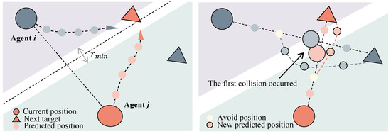
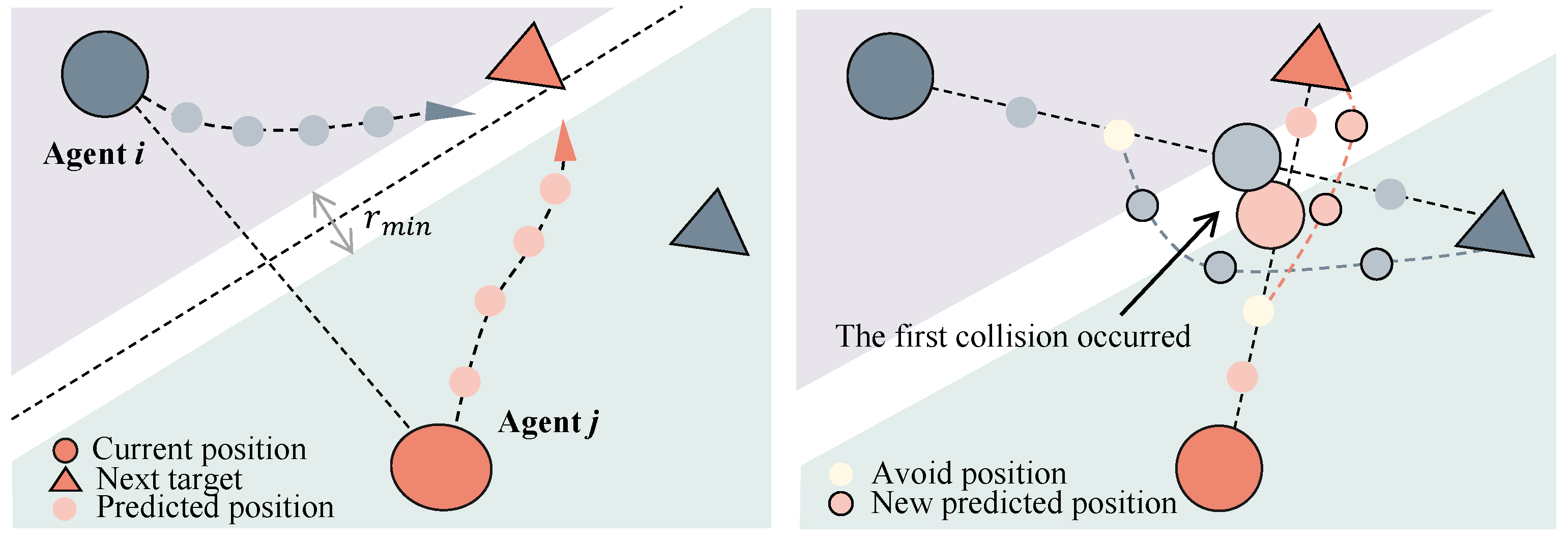
While non-convex distance constraints (8) provide a safety baseline, they impose significant computational burdens in high-density swarms. Traditional BVC methods simplify computation through static linearization, yet often trigger feasible space collapse within narrow tubes, as shown in Figure 2. To address this, we propose a Risk-Aware Activation mechanism. By leveraging predictive state sharing, this strategy dynamically triggers safety constraints only when a collision risk is imminent. This demand-driven approach prevents excessive compression of the feasible region, ensuring the recursive feasibility of the DMPC solver even under stringent spatial limitations.
Figure 2.
Comparison of collision avoidance strategies. (Left) Solution space collapse under static constraints. (Right) Proposed risk-aware activation with dynamic predictive updates.
Let denote the assumed predicted trajectory (APT) neighbor j received by agent i at the current time . Under the assumption of synchronous information exchange, the non-convex reciprocal collision avoidance between agent i and j can be linearized by constructing a hyperplane that bisects the predicted relative distance. Taking into account the scaling effects of downwash and uncertainty, the decoupled safety region for agent i relative to neighbor j is formulated as follows, according to [33].
where the explicit expressions for and are:
Here, and are the known predicted trajectory points, while is the variable to solve. For any pair of interacting agents, the reciprocal safety requirement is decoupled into two symmetric linear constraints: and .
To prevent the collapse of the feasible solution space within constrained virtual tubes, we implement a Risk-Driven On-Demand Activation mechanism. Unlike conventional approaches that impose safety constraints across the entire prediction horizon, this strategy dynamically activates the collision-avoidance constraint only upon detecting an imminent collision risk. The activation set for agent i is defined as:
By evaluating the predicted relative distance throughout the horizon K, this mechanism incorporates a forecast time window of into the risk assessment. Any potential conflict detected within this period triggers immediate constraint activation at the current time step, which ensures proactive safety and reduces numerical complexity by pruning redundant constraints. Once a potential collision is predicted at step , it indicates that the distance between the two drones has entered a danger zone. At this point, not only must that specific step be avoided, but all subsequent planning steps must satisfy the linearized BVC constraint (24). If the above set is empty for all k, it indicates that no collision risk exists.
To integrate these step-wise constraints into the DMPC framework, the inequalities are stacked over the prediction horizon K and mapped to the decision space. The predicted position sequence is expressed as a function of the control sequence and the current state , allowing the local constraints to be reformulated into a compact matrix form:
where and are dynamically constructed based on the anisotropic scaling matrix and the risk trigger step . Specifically, for steps where , corresponding rows are zero-padded to maintain dimensional consistency while disabling the constraints. This formulation enables the DMPC to solve the conflict resolution problem as a high-efficiency QP problem.
3.3. Dynamic Tube Reconstruction and Constraint Design
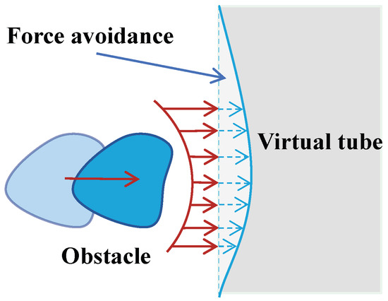
While the virtual tube provides a persistent guidance infrastructure, its static geometry often compromises recursive feasibility in dense, dynamic environments, leading to potential solution-space collapse. To mitigate this, we propose an elastic reconstruction strategy that adaptively deforms the tube’s topology, as shown in Figure 3. By treating the boundary as a flexible string model, this approach enables real-time boundary correction in response to environmental disturbances, ensuring continued feasibility without sacrificing the structural integrity of the guidance.
Figure 3.
Schematic of the adaptive mechanism of the virtual tube under obstacle intrusion. The red solid arrows represent the repulsive force generated by the obstacle, while the blue dashed arrows indicate the adjustment trend of the virtual tube boundary.
At each optimization time step , the discrete waypoint sequence along the tube centerline is treated as a topologically elastic sequence . When a dynamic obstacle intrudes into the safety margin at time while agents are operating nearby, the local centerline waypoint experiences a virtual repulsive force from the obstacle, displacing it away from the obstacle. According to the potential-field principle, this force is defined as the negative gradient of the obstacle potential function:
This local concession mechanism is equivalent to dynamically reconstructing collision-free space through a nonlinear mapping at time . Furthermore, we define the obstacle potential function as follows:
where is the scaling gain that determines the magnitude of the repulsive force and is a small positive constant utilized to prevent numerical singularity when the distance approaches zero. Furthermore, denotes the physical Euclidean distance between the waypoint and the center of obstacle , while represents the normalized distance. is the radius of safety influence that defines the threshold distance to activate the repulsive potential. Specifically, the potential field is activated only when an obstacle enters this range to trigger the adaptive deformation of the tube.
To ensure the structural continuity of the route as infrastructure, we apply a Gaussian-kernel convolution to the deformed sequence, generating a smooth path with continuity:
where denotes the Gaussian weight. For waypoints distal to conflict zones, the system maintains their nominal states to preserve computational efficiency. Throughout the dynamic adjustment process, the following core criteria must be strictly adhered to:
- Constant Spatial Clearance: Throughout the centerline shifting, the safety radius remains constant, ensuring that the re-planned tube still provides sufficient physical clearance for the swarm to occupy and traverse safely.
- Temporal Smoothness Constraint: To prevent instantaneous jumps of the safe spatial region, the update of the centerline must satisfy temporal smoothness. Geometric continuity must be maintained between the original and new centerlines, with fixed endpoints (), ensuring that UAVs do not generate infeasible motion commands due to abrupt constraint changes.
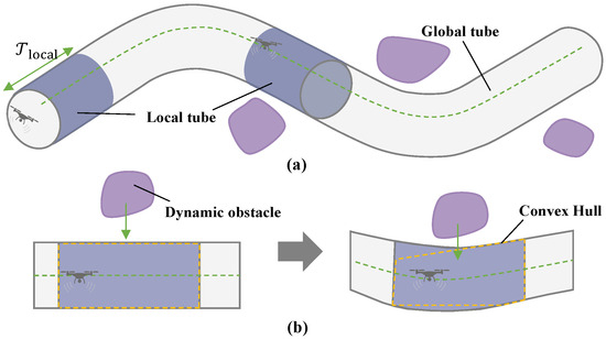
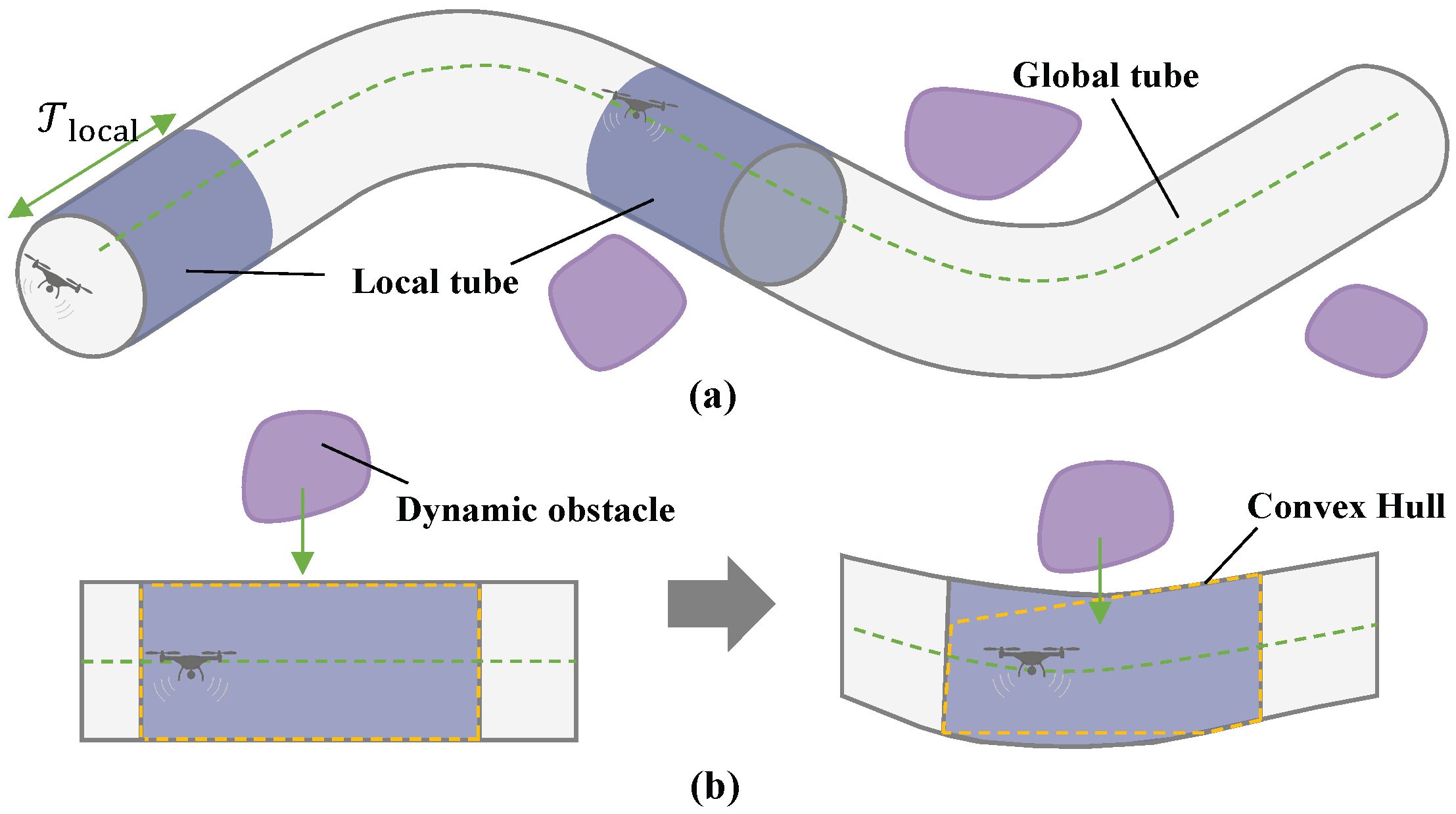
Since the original tube constraint (15) is non-trivial to handle directly in real-time optimization, it must be reformulated into a linear form to facilitate rapid onboard computation. Considering the limited computational power and sensing range of the UAV, a local tube segment is extracted at time step based on the agent’s position within the tube and its field of view (FOV) . By sampling and computing its convex hull, a convex set is obtained, as shown in Figure 4.
Figure 4.
Dynamic extraction and real-time update of the local tube. (a) Intercepting a sub-tube from the global path based on the current sensing horizon. (b) Continuous reconstruction of the tube to accommodate ego-motion and dynamic obstacle trajectories.
Following the extraction of the local convex polyhedron , it must be transformed into a format suitable for optimization solvers. Inspired by [34], by leveraging the geometric properties of hyperplanes, the tube constraints for agent i over the predictive horizon can be equivalently formulated as a set of linear inequalities with respect to the predicted states :
The matrices and characterize the tube boundary for agent i at each discrete predictive time step k as the set . This time-indexed formulation accounts for the spatio-temporal evolution of local constraints as the agent progresses along the tube. To maintain computational efficiency for online operations, the convex hull is deliberately simplified to minimize the number of vertices, thereby reducing the number of constraints and the associated computational overhead.
Typically, for a static tube, the local segment constructed at the current time remains valid throughout the entire predictive horizon h. Furthermore, as long as the agent has not reached the local sub-goal within its FOV, the local tube constraints can be considered persistent for future time steps. Nevertheless, due to the evolving environment and the varying states of the agent, the convex hull must be updated when the following triggering conditions are met:
- Time Trigger: The time-driven mechanism ensures a minimum update frequency to counteract sensor drift or unforeseen environmental disturbances. Even if the agent remains stationary or moves slowly, a re-sampling and convex hull reconstruction are forced once the elapsed time since the last update exceeds a maximum threshold .
- Obstacle Motion Trigger: When the perception system detects a significant deviation in the trajectory of a dynamic obstacle at time , particularly if its predicted path encroaches upon the tube’s safety margin, an immediate re-planning of the local tube segment is triggered.
- Task-Driven Trigger: Addresses look-ahead requirements as the agent approaches the local target . The system updates to extend spatial coverage, ensuring trajectory feasibility and preventing solver failure due to insufficient search space over the next horizon K.
To integrate tube constraints into the DMPC framework, the spatial constraints based on predicted states must be reformulated in terms of the control sequence to be optimized. Based on Formula (21), let and denote the stacked linear constraint matrices over the entire prediction horizon K. By substituting the state transition matrices and , the original constraints can be reformulated as the following affine function of the control input sequence :
3.4. Objective Function
The cost function in (10) is designed to balance navigation progress, energy efficiency, and motion smoothness. It consists of the following three components:
(1) Target attraction penalty: To drive the agent through the virtual tube, this term minimizes the quadratic distance between the predicted terminal position and the current active sub-target . Unlike traditional trajectory tracking that penalizes deviations from a continuous path, this formulation provides a directional incentive for the agent to advance toward successive waypoints. The penalty is expressed as:
where and is a positive definite weight matrix and is the sub-target point. Here, denotes the current active sub-target within the tube. When the agent approaches the vicinity of , the sub-target is updated to the next waypoint within the agent’s sensing horizon. This look-ahead mechanism ensures continuous forward progression, allowing the agent to adapt its local path within the tube’s boundaries until the final destination is reached. Define the matrix , bringing Formula (21) into (33) to get:
(2) Energy consumption penalty: To minimize control effort and prevent excessive actuator wear, a quadratic penalty on the control input sequence is incorporated:
where denotes the control effort weight matrix.
(3) Input variation penalty: To ensure temporal smoothness in control commands and prevent abrupt jumps, a quadratic penalty is incorporated on the input variations. This smoothing term is essential for maintaining the physical stability of the agent and extending the lifespan of its actuators. The penalty is formulated as:
where is the control variation rate weight. The difference relation can be represented by the matrix , while is defined as a reference vector, in which denotes the actual control input executed at the previous time step and all remaining elements are set to zero.
By substituting these definitions, the Formula (36) can be rewritten as:
The complete cost function can be written as:
To construct an optimization framework suitable for real-time processing, the constraints encompassing the virtual tube boundaries, inter-agent collision avoidance, and physical performance limits are vertically stacked into a unified linear expression . By leveraging the linear predictive model defined in (16), the state evolution is implicitly integrated into the constraint set and the objective function as affine mappings of the control sequence . Consequently, the optimal tube traversal planning problem for each agent i can be compactly formulated as a condensed-form QP problem:
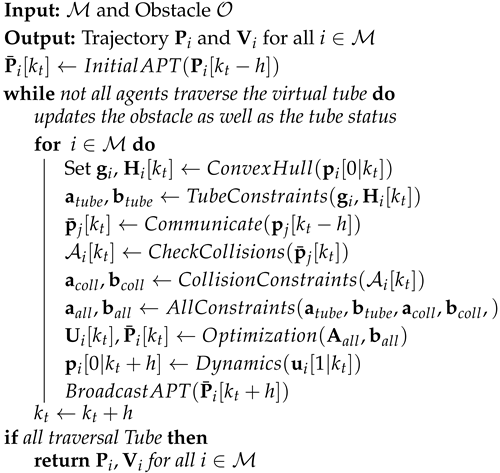
where and encapsulate the stacked constraints from (23), (27), and (32). Note that because the precise future states of neighboring agents are not directly observable, they are approximated using their latest predicted trajectories obtained via inter-agent communication. This estimation maintains consistency within the distributed framework while ensuring real-time computational efficiency. Algorithm 1 outlines the complete procedure of our proposed method.
| Algorithm 1: Trajectory generation and tube-based navigation for UAV swarms. |
 |
4. Experiments
To evaluate the effectiveness and robustness of the proposed dynamic tube-based DMPC framework, both numerical simulations and real-world flight experiments were conducted. All computational tasks were executed on workstations equipped with 13th Gen Intel(R) Core(TM) i7-13700KF (3.40 GHz) processors and 64-bit operating systems, utilizing MATLAB 2022b as the primary development and simulation environment.
4.1. Parameter Settings
To evaluate the proposed algorithm, this section presents two simulation scenarios: swarm traversal within both static and dynamic virtual tubes. The simulations are executed in a synchronous distributed manner following the sequence of Algorithm 1.
The quadrotors are subject to strict physical and kinematic limits to ensure flight feasibility. Each agent has a physical safety radius =0.1 m, with the baseline minimum separation defined as m. To ensure dynamic agility while maintaining stability, the maximum acceleration and velocity are capped at = 2 m/s2 and m/s, respectively. A scaling factor is applied to the vertical dimension of the collision ellipsoid to mitigate downwash disturbances between agents. Following the methodology in [32], the localization uncertainty is modeled with a covariance (0.03 m, 0.03 m)2, corresponding to a standard deviation of m. Assuming the localization error follows a zero-mean Gaussian distribution and given a collision probability threshold corresponding to a confidence level, the uncertainty bound is computed as m. Hence, the final minimum safe distance between two UAVs is m. This value is consistent with the parameters listed in Table 1 and is validated by hardware experiments.
Table 1.
Parameters for UAV swarm trajectory planning.
Regarding the temporal parameters, the simulation employs a sampling time of s and a prediction horizon of , providing a 3.0 s look-ahead window to ensure reactive agility. It is worth noting that the parameters for hardware experiments are set more conservatively compared to the simulation. Specifically, h is increased and is reduced in the hardware tests to accommodate the communication latency of the motion-capture system and the physical response limits of the propulsion system. Despite these numerical differences, the underlying dimensionless coordination logic and safety constraints remain consistent. All simulation results are processed and visualized on the x-y plane at a constant flight altitude.
4.2. Simulation Experiment
To evaluate the performance of the proposed framework, Table 2 summarizes key performance indicators across static and dynamic scenarios. The mission efficiency is reflected by the total time required for the swarm to complete the traversal. To verify the feasibility of the synchronous distributed architecture, we record the maximum and average solving times among all agents, representing peak and mean individual computational demands. Finally, safety integrity is quantified by the minimum inter-agent distance and the relative safety buffer (the percentage of remaining distance beyond the threshold ), which together demonstrate the system’s safety redundancy.
Table 2.
Results of UAV Swarm Trajectory Planning.
4.2.1. Static Virtual Tube Scenarios
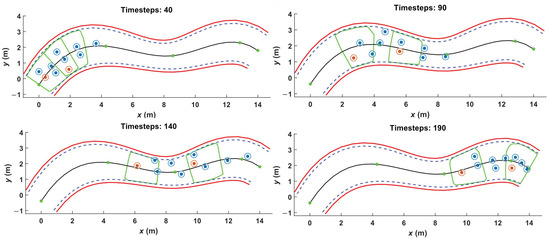
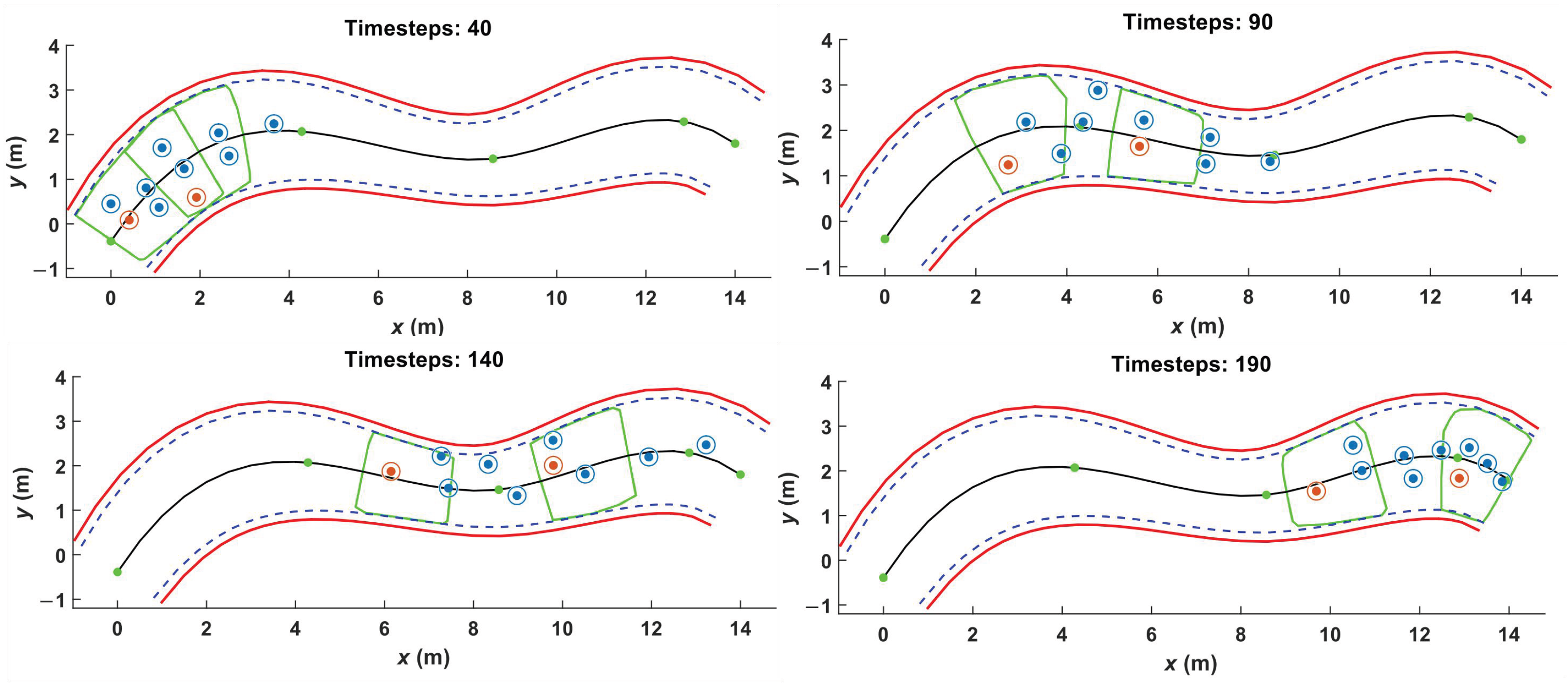
Consider a swarm consisting of agents tasked with traversing a static virtual tube generated from a sequence of predefined discrete waypoints. Figure 5 presents snapshots captured at four distinct temporal instances during the simulation.
Figure 5.
Snapshot of 10 agents in a static tube scenario.
At the initial state, all agents are deployed at the tube entrance, with circular regions representing their respective safety expansion zones. To visualize the morphology of the solution space, two agents are randomly selected and highlighted in red. The green convex hull regions represent the local feasible workspace determined by the current sensor detection range of the marked agents. These regions are dynamically updated according to the agent’s real-time position, tube geometry, and environmental perception. The static tube is defined with a varying width, where the narrowest section has a radius of 0.8 m and the widest section has a radius of 1.2 m. Furthermore, the area bounded by the blue dashed lines indicates the effective navigable tube volume, accounting for the physical occupancy models of the agents.
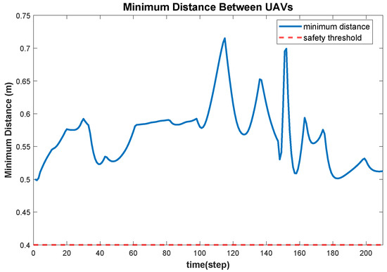
Combined with the parameters in Table 2, a statistical analysis of the inter-agent distances, as shown in Figure 6, indicates that the minimum separation distance is maintained at 0.4985 m. This provides a 24.62% safety margin relative to the prescribed 0.4 m safety threshold. Furthermore, by analyzing the agents’ positions relative to the tube boundaries as shown in Figure 7, it is evident that the clearance between all agents and the inner tube wall remains consistently above 0 m. These results demonstrate that all agents strictly adhere to the virtual tube constraints, with no boundary violations occurring throughout the mission.
Figure 6.
Minimum distance among 10 agents during tube traversal.
Figure 7.
Distance from 10 agents to tube boundary.
As summarized in the computational performance metrics in Table 2, the average execution time for a single optimization problem within the swarm of 10 agents is only 0.97 ms. Although a maximum latency of 226.32 ms was recorded in extreme conflict scenarios primarily due to the warm-start overhead during the initial activation of non-convex constraints—the average solving time remains significantly lower than the 200 ms sampling period.
The occasional peak latency slightly exceeding the sampling interval does not compromise system stability, as the high-frequency low-level controller maintains state consistency during these brief optimization updates. The minimal average computational overhead demonstrates that the distributed architecture effectively disperses the computational load, meeting the real-time online planning requirements for large-scale agent swarms in complex missions. Consequently, the entire swarm successfully completed the traversal task in 42.20 s, achieving high-flow efficiency in the 14 m tube.
4.2.2. Dynamic Virtual Tube Scenarios
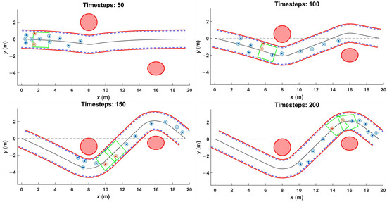
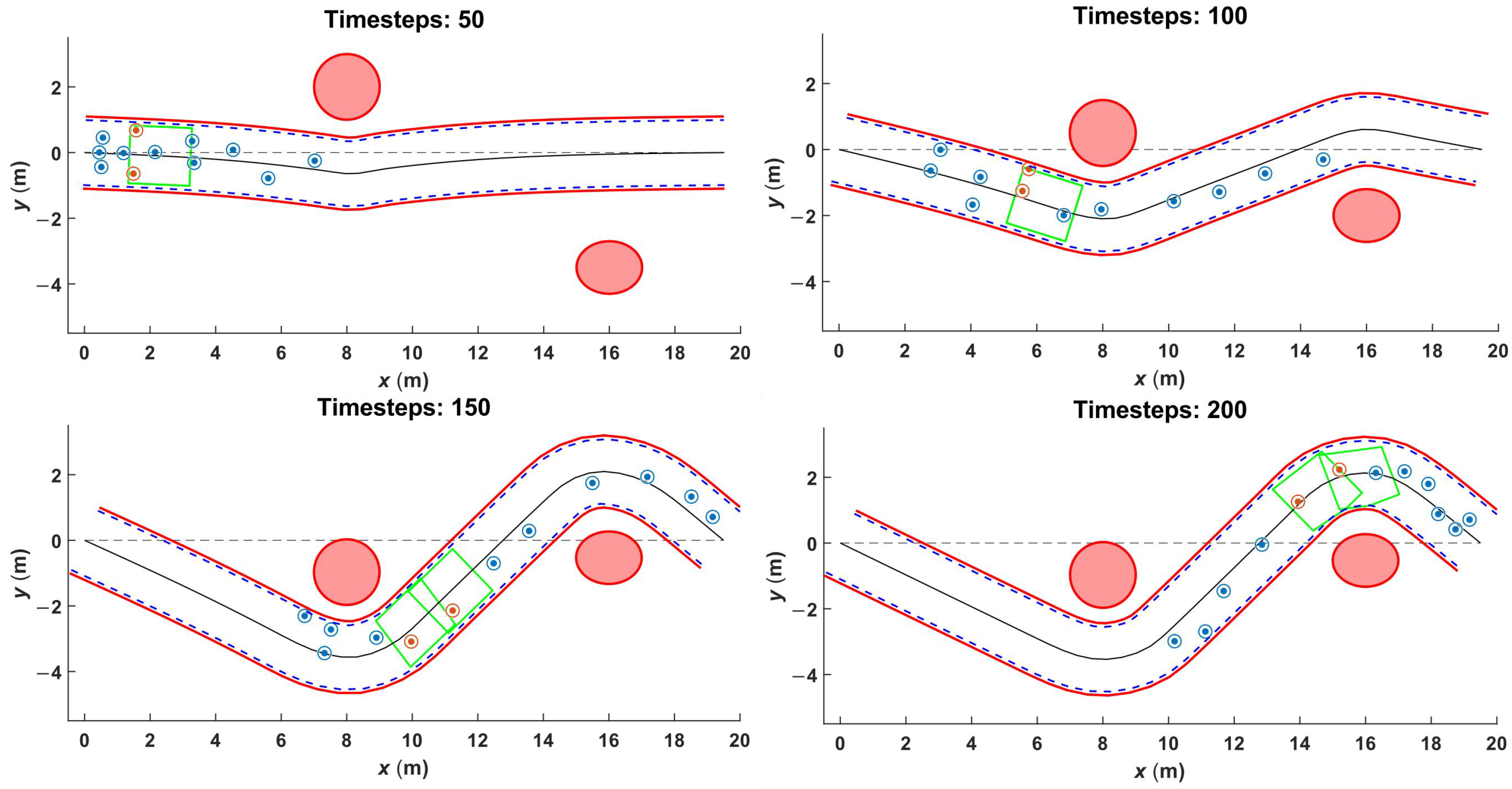
This experiment configures a swarm of agents to traverse a dynamic virtual tube, with Figure 8 presenting four snapshots captured during the simulation.
Figure 8.
Snapshot of 12 agents in a dynamic tube scenario.
The nominal tube radius is set to 1 m, while the effective inner radius is 0.8 m. Two dynamic obstacles, represented by red solid ellipses and moving at a velocity of 0.3 m/s, are introduced to intrude into the predefined tube from different directions. When the distance between the nominal tube and an obstacle falls below a preset threshold of 1.5 m, the boundary undergoes real-time adjustment based on the proposed elastic deformation model. It is worth noting that the proposed mechanism treats these dynamic obstacles as non-cooperative intruders that do not communicate with the cooperative agents. While the local boundaries shift to bypass the intruding obstacles, the global topological continuity of the tube remains strictly preserved throughout the process.
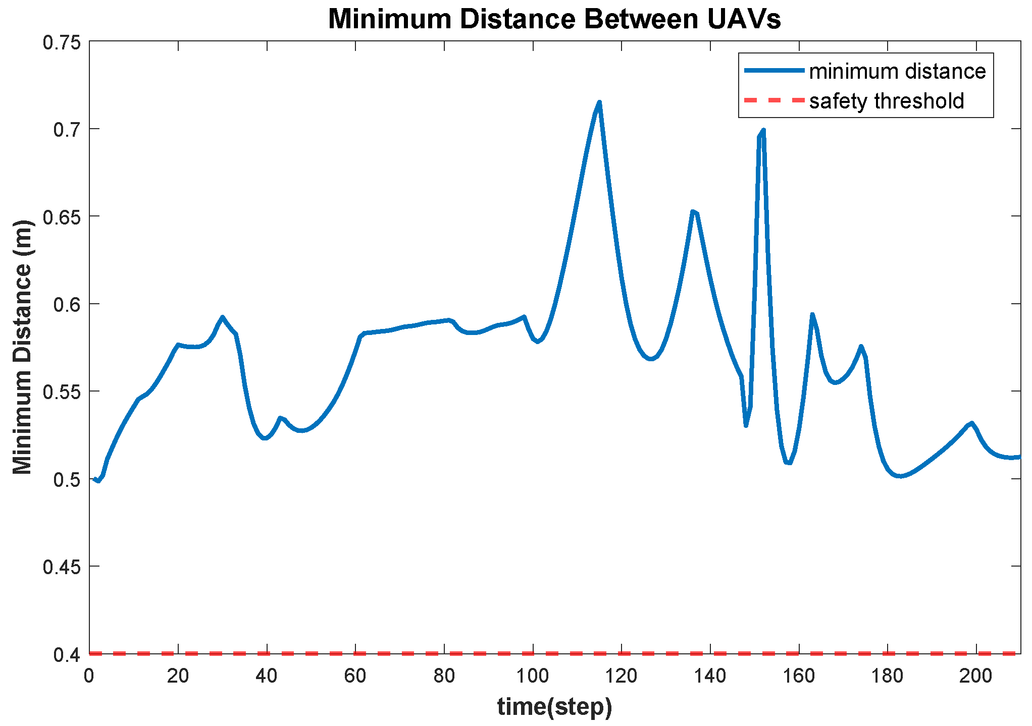
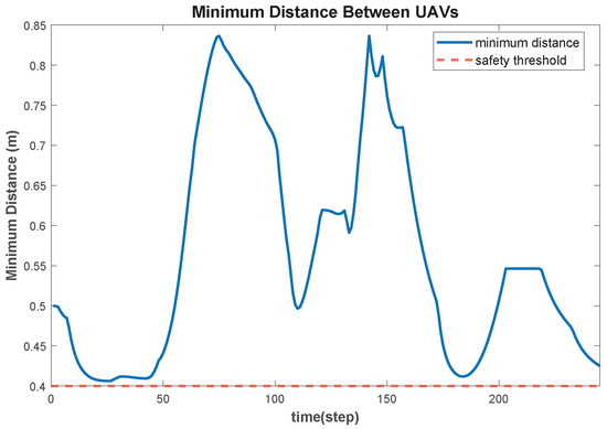
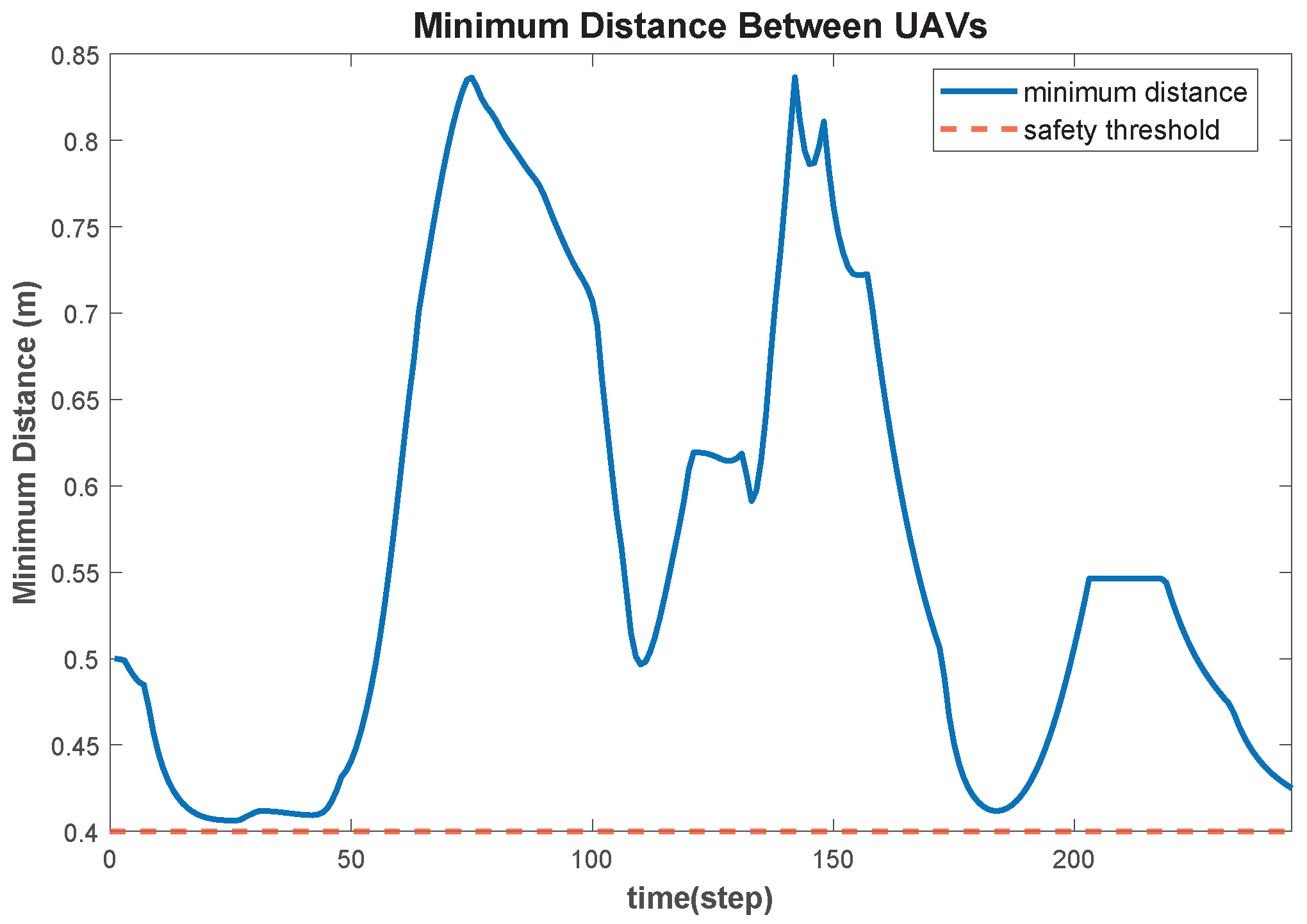
The statistical results of the dynamic simulations further validate the efficacy and robustness of the proposed framework under active spatial competition. As shown in Figure 9 and the data in Table 2, the minimum inter-agents separation distance recorded throughout the entire mission is m, which remains strictly above the m safety threshold.
Figure 9.
Minimum distance among 12 agents during tube traversal.
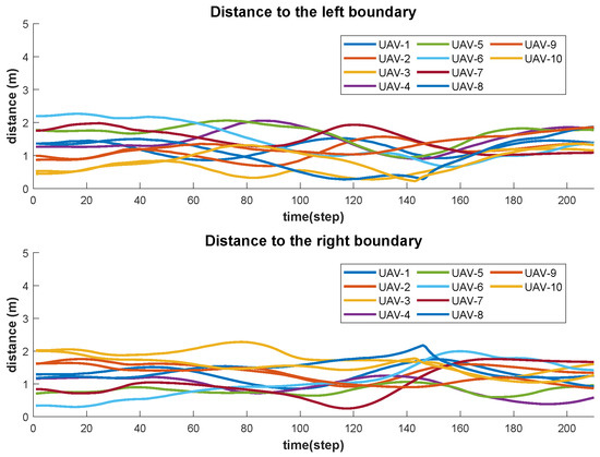
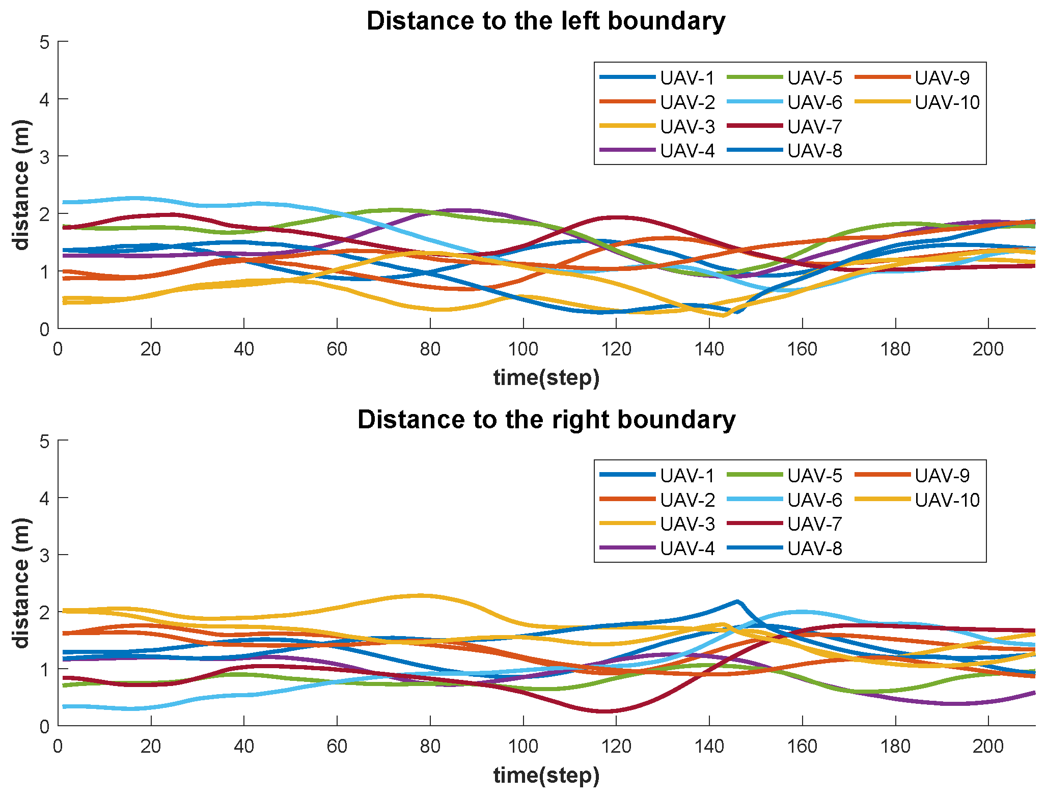
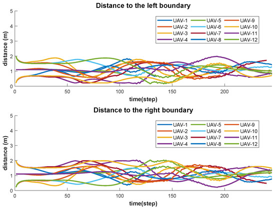
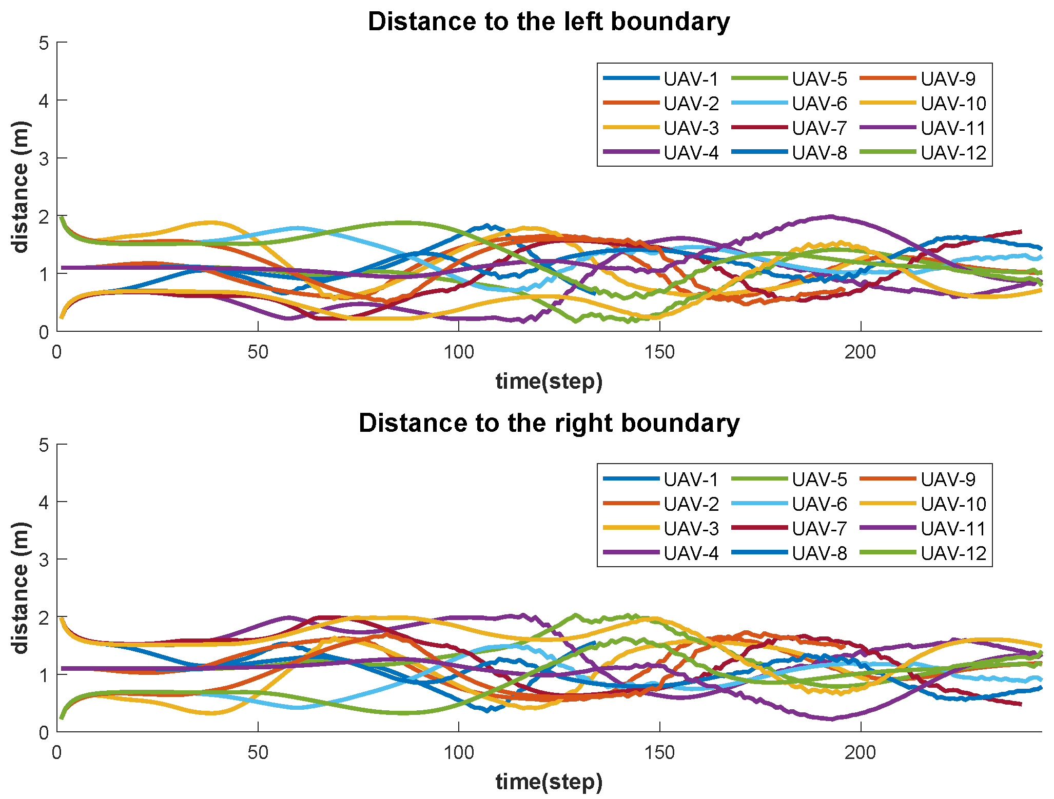
The obstacle avoidance performance is further shown in Figure 10. Throughout the entire navigation mission, the distances between all 12 agents and the left and right boundaries of the dynamic tube are consistently maintained at positive values. This quantitatively confirms that the proposed DMPC framework strictly enforces the spatial constraints, ensuring that no agent violates the tube’s safety boundary even during local deformations triggered by moving obstacles. Notably, the distance curves for several agents terminate before reaching the maximum simulation time step. This behavior is attributed to these agents reaching the goal tolerance area ahead of the rest of the swarm. Upon arriving at the exit of the m tube, these agents transitioned into a terminal hovering state.
Figure 10.
Distance from 12 agents to tube boundary.
Regarding computational efficiency, the decentralized architecture maintains superior performance despite the increased complexity of time-varying constraints. The average optimization solving time is merely ms, with a worst-case peak of ms. Given the sampling period ms, the algorithm utilizes only 1.48% of the available time budget on average. This leaves substantial headroom for auxiliary onboard tasks such as flight control and environmental perception, highlighting the numerical stability of the formulation and its real-time feasibility for embedded deployment. Ultimately, the swarm successfully traversed the m dynamic tube within 49.20 s. These findings confirm that the dynamic tube reconstruction mechanism provides a reliable and computationally tractable workspace, ensuring the safe and efficient coordination of large-scale UAV swarms in highly dynamic and non-convex environments.
4.3. Hardware Experiments
The proposed hardware verification framework primarily consists of a CMTracker motion capture system, a ground station assembly, and a quadrotor swarm. The experiments utilize FS-J150 micro-quadrotors (Zhuoyi Intelligence Technology Co., Ltd., Beijing, China), whose technical specifications are detailed in Table 3. Each UAV is equipped with a Pixhawk based flight control system that supports real-time position feedback. The CMTracker motion capture system, featuring 12 high speed cameras, captures visual data from markers mounted on the quadrotors to resolve high-precision pose information. The ground computing infrastructure consists of two computers linked via a local area network. Computer 1 serves as the data acquisition hub that processes raw motion data to obtain precise state information of the UAVs and transmits these data to computer 2 through the network.
Table 3.
Technical Specifications of the FS-J150 Micro Quadrotor.
Following the established experimental paradigms in multi-UAV research [24,35], computer 2 is configured to simulate a multi processor environment. Specifically, the DMPC algorithm for each UAV is encapsulated within an independent computational thread in a parallel Simulink environment. During each sampling interval, each thread retrieves only the state of its corresponding agent and information from its neighbors to solve the local optimization problem independently without a central coordinator. Control commands are subsequently transmitted to the onboard flight controllers via wireless communication to drive the maneuvers of the quadrotors.
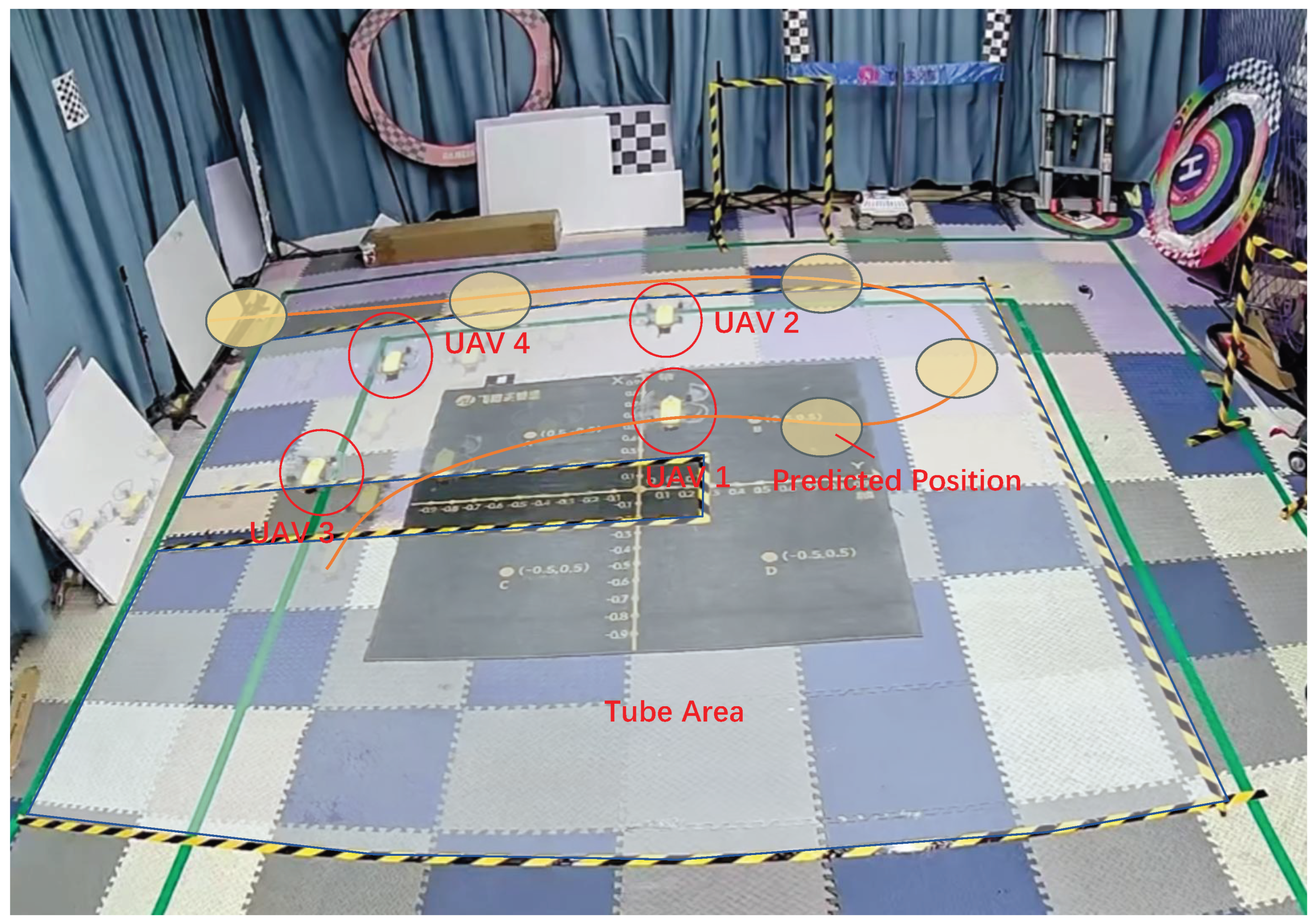
In this implementation, the algorithmic planning frequency is set to 2 Hz (h = 0.5 s), while the low-level control frequency is maintained at 30 Hz. Following the proposed error-aware collision avoidance model, the minimum inter-UAV distance is established at 0.4 m, with other parameters consistent with Table 1. The initial experiment is conducted in a static tube scenario. As shown in Figure 11, the yellow-and-black warning lines on the ground represent the virtual tube projected upward into the flight space. Four quadrotors take off from an initial rectangular formation and navigate within an altitude range of 0.9–1.2 m, planning their motions inside the tube to reach the designated goal. The tube is configured within a spatial volume of m, with a total centerline length of 8 m.
Figure 11.
Quadrotor experiment in static scenario.
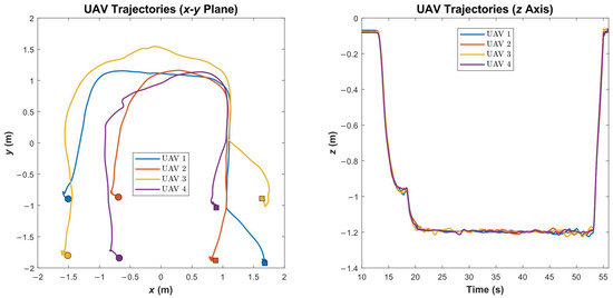
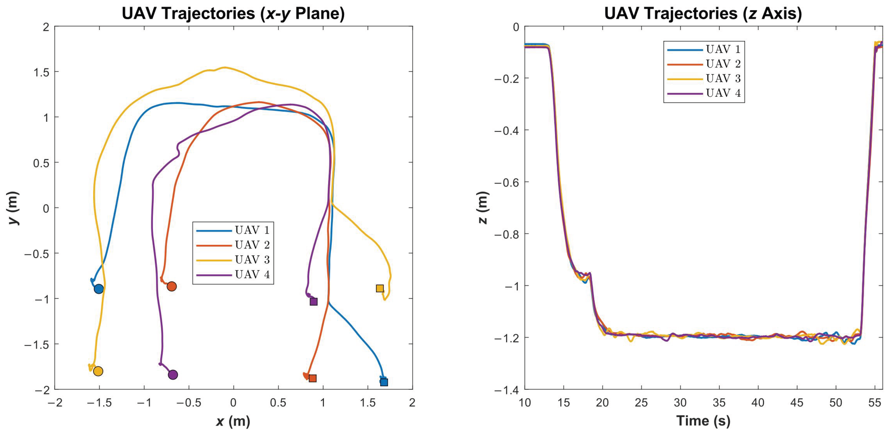
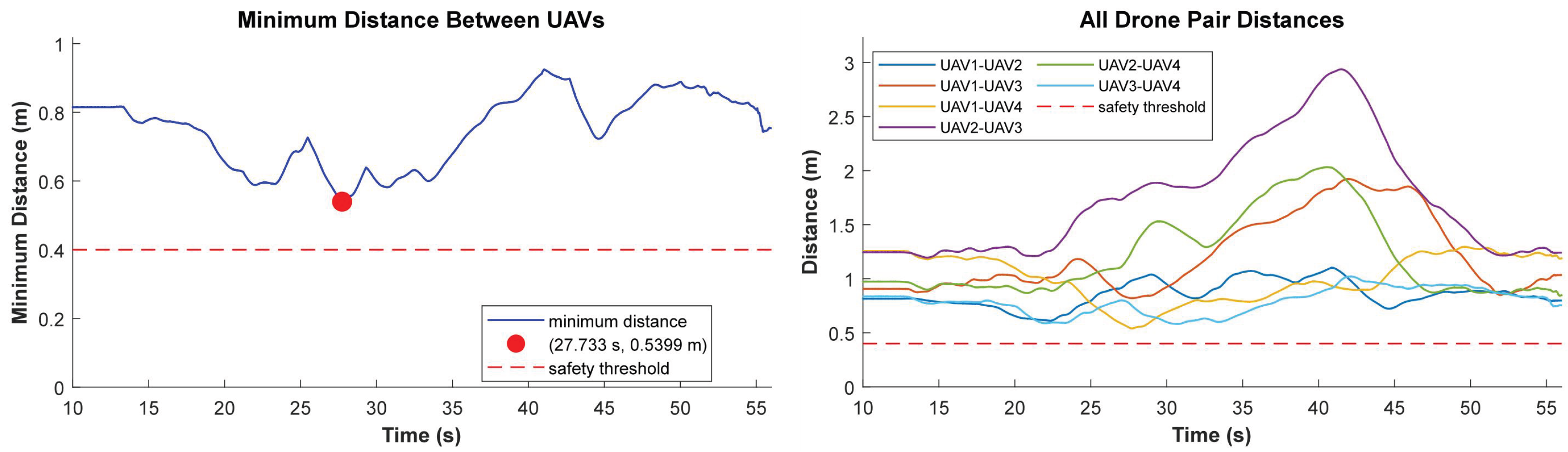
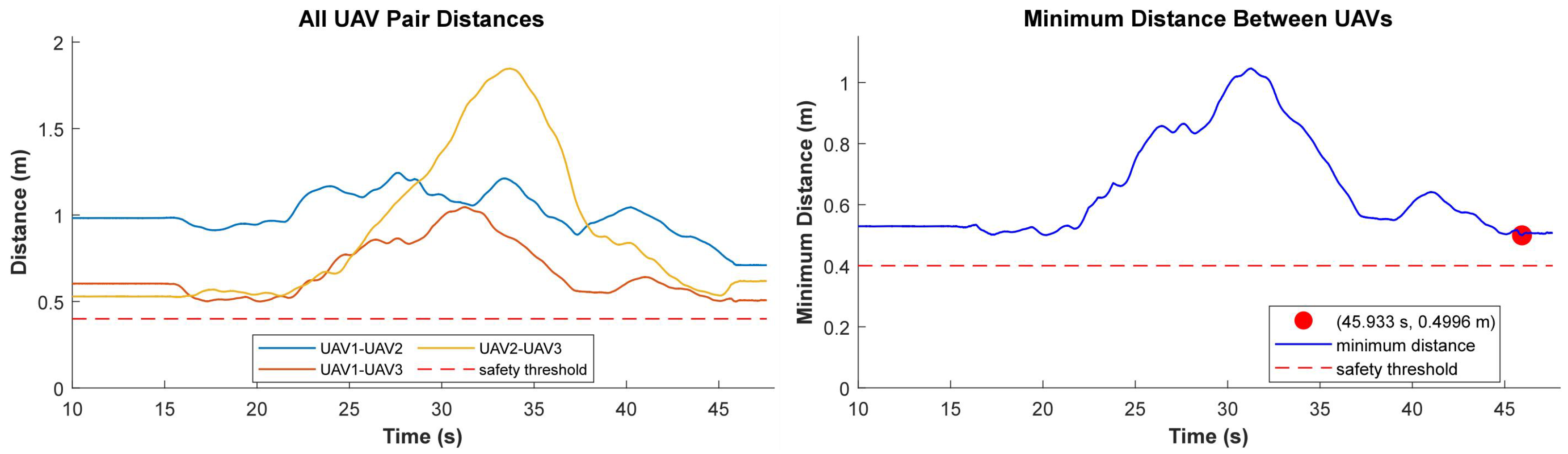
The trajectories of the UAVs are shown in Figure 12. During this navigation mission, the swarm takes off from their initial positions and performs autonomous motion planning within the tube, reaching the designated goal while strictly maintaining flight safety and adhering to boundary constraints. The entire traversal was successfully completed within an effective flight time of 45 s. Despite the presence of complex aerodynamic downwash effects and localization noise inherent in the experimental environment, Figure 13 demonstrates that the minimum inter-UAV separation distance was maintained at 0.5399 m, consistently exceeding the 0.4 m safety threshold. This results indicates that even under the influence of physical disturbances, the proposed collision avoidance control algorithm effectively maintains a reliable safety margin.
Figure 12.
The trajectories of the UAV swarm within static tubes.
Figure 13.
Evolution of inter-agent distances during static virtual tube navigation.
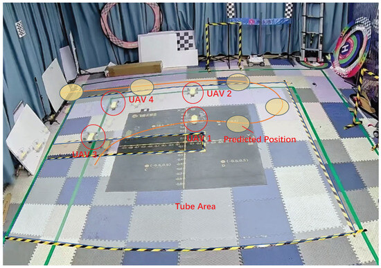
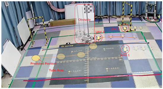
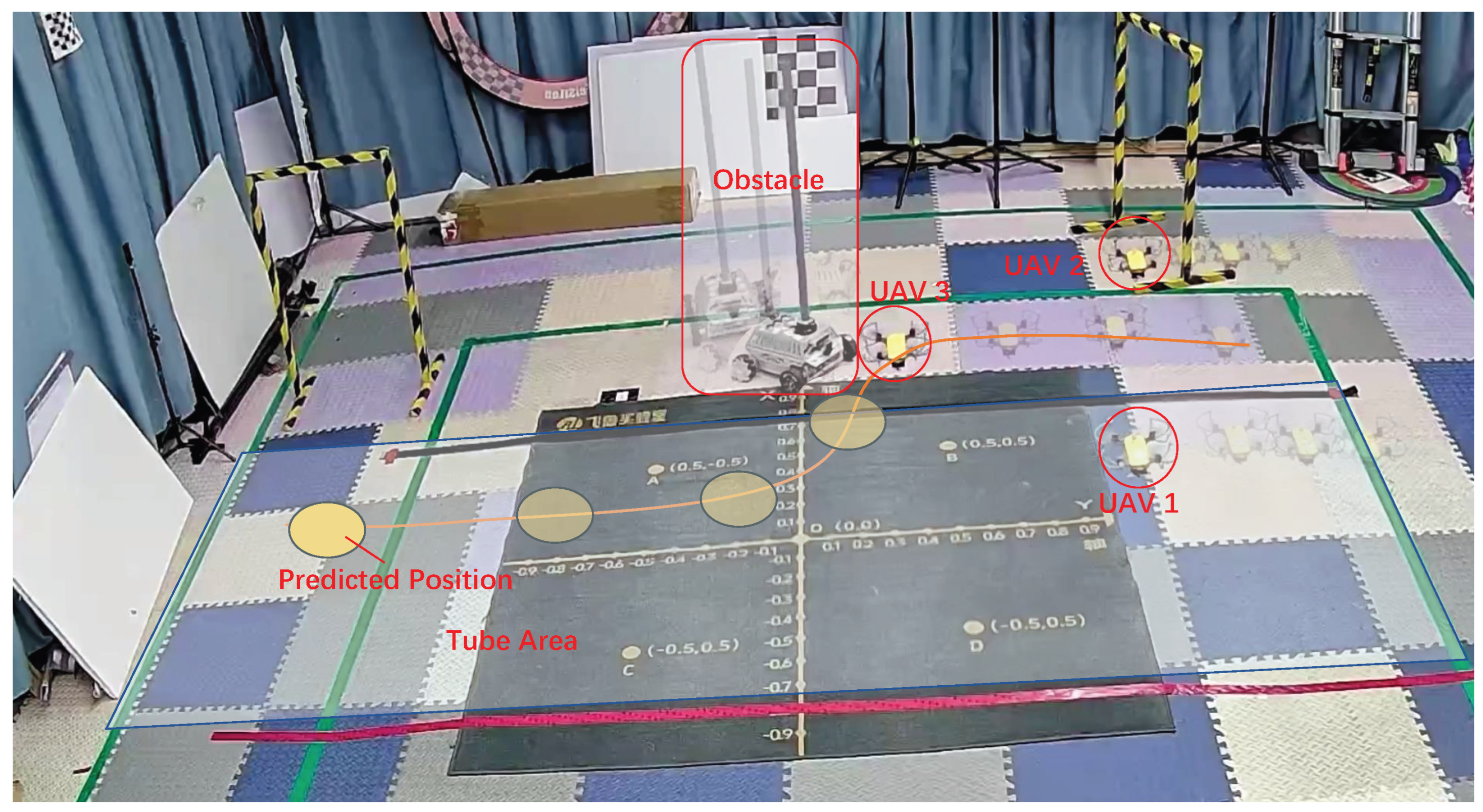
Figure 14 shows the scenario of the second physical experiment. The red and black boundary lines on the ground represent the initial predefined virtual tube projected upward into the airspace. A ground vehicle is employed as a dynamic obstacle, occupying a spatial volume of 0.32 × 0.32 × 1.4 m. Three quadrotor UAVs are deployed from the tube entrance to execute the traversal task. To ensure sufficient clearance from the tube boundaries and maintain safety relative to the obstacle, the minimum distance between the UAVs and the obstacle is set at 0.5 m, while the flight altitude is maintained within the range of 0.6–0.8 m.
Figure 14.
Quadrotor experiment in dynamic scenario with obstacles.
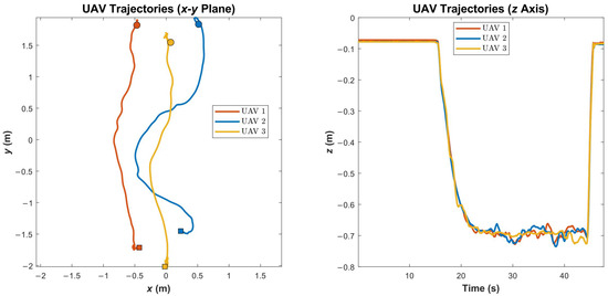
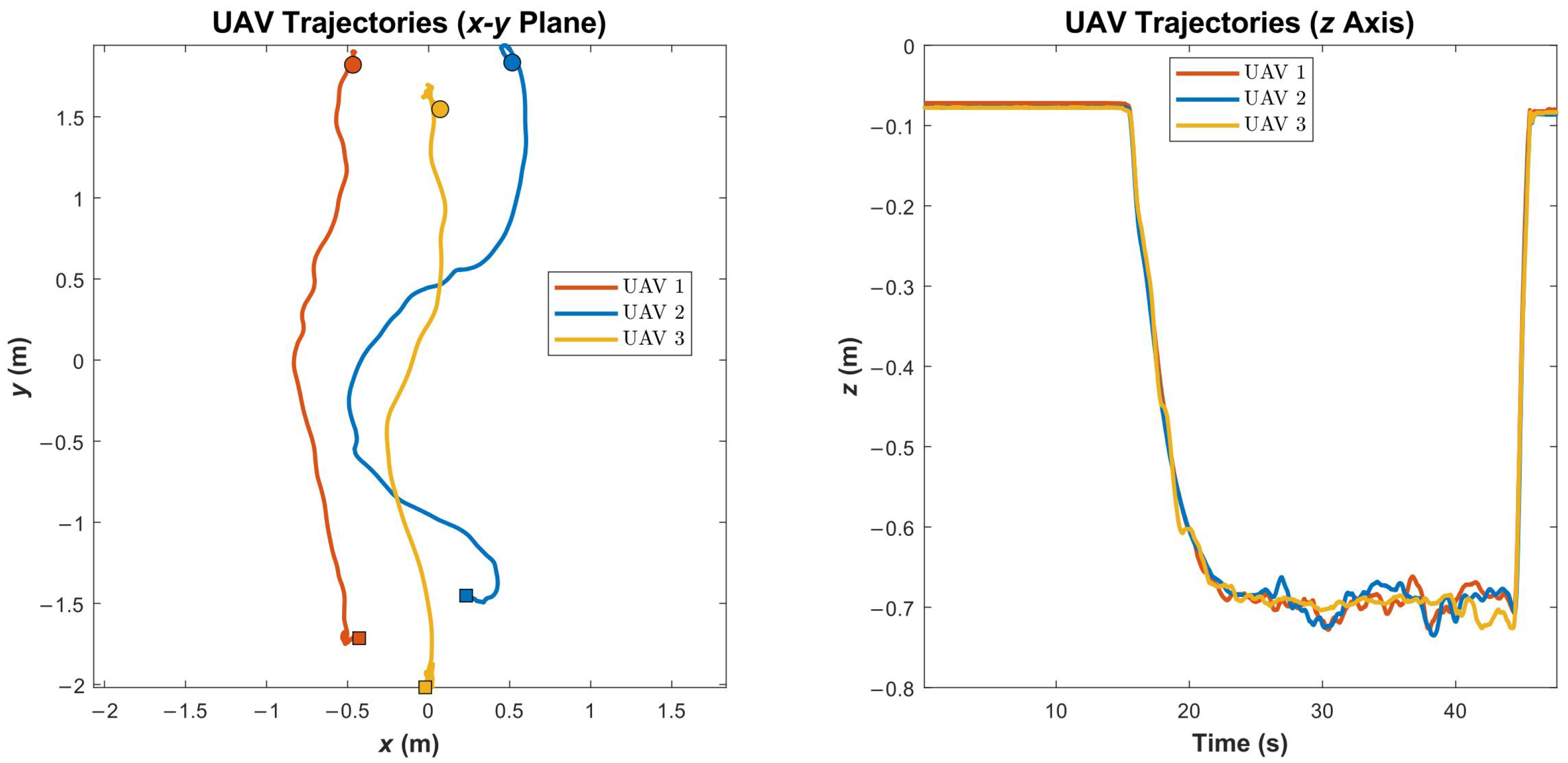
Based on the experimental data presented in Figure 15 and Figure 16, the effective flight duration of the navigation mission is 34 s, excluding the initial takeoff preparation phase. Throughout this process, the system exhibited high responsiveness. Specifically, when the distance between the dynamic obstacle and the tube boundary fell below the predefined threshold of m, the tube boundary underwent real-time reconstruction on a millisecond scale based on the proposed elastic model.
Figure 15.
The trajectories of the UAV swarm within dynamic tubes.
Figure 16.
Evolution of inter-agent distances during dynamic virtual tube navigation.
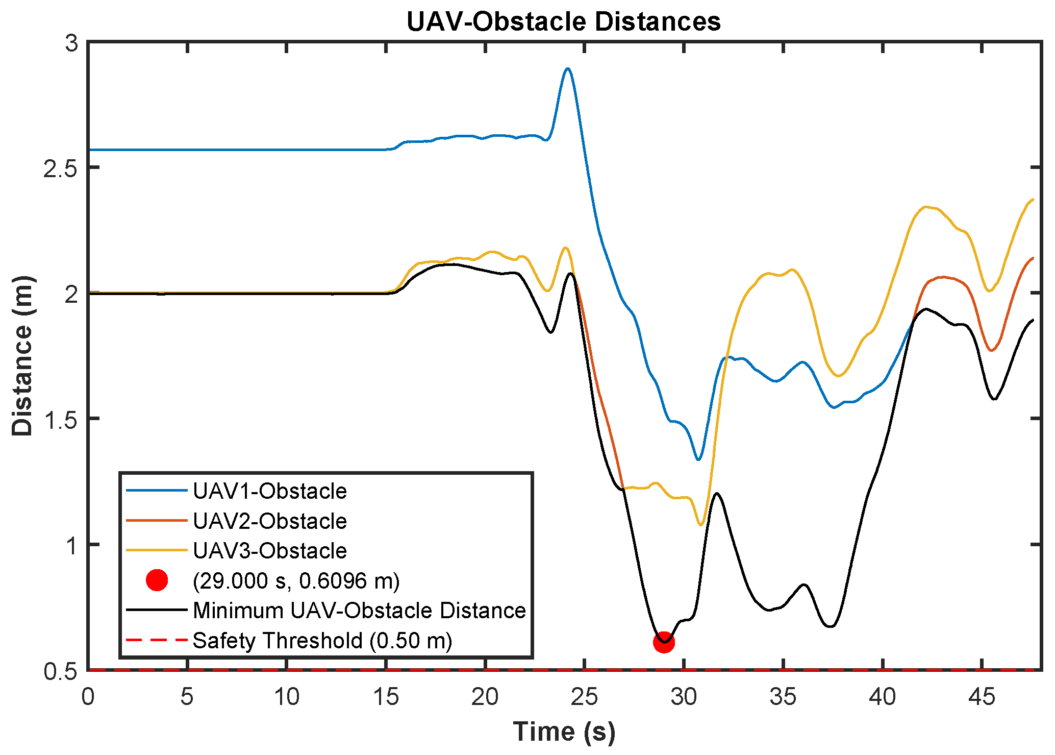
As shown in Figure 17, the minimum inter-UAV separation distance during the obstacle avoidance phase was m, providing a safety margin of approximately 24.9% relative to the m safety threshold. This confirms that even during significant tube boundary deformations, the DMPC framework effectively coordinates the agents to prevent inter-agent conflicts arising from spatial compression. Simultaneously, robust physical isolation was maintained between all UAVs and the dynamic ground obstacle. The recorded minimum UAV-to-obstacle distance was m, consistently exceeding the m avoidance threshold. Furthermore, the results underscore the topological integrity of the dynamic tube, which ensures a collision-free workspace for the swarm. These quantitative findings demonstrate the efficacy of the proposed elastic tube mechanism and the distributed computational logic. The demonstrated real-time performance and the decoupled nature of the algorithm provide strong evidence for the feasibility of transitioning this architecture to fully decentralized onboard systems [24].
Figure 17.
Distance variation between UAVs and obstacles.
5. Conclusions
To ensure safe and efficient multi-UAV swarm navigation in constrained environments, we present a new DMPC framework based on persistent virtual tubes. A local dynamic elastic deformation mechanism is introduced to balance global topological stability with local maneuverability. Furthermore, a risk-aware strategy is developed to prevent “solution space collapse” in dense traffic, optimizing computational efficiency without sacrificing agility. Both simulations and hardware experiments show that our approach guarantees recursive feasibility and safety under intense spatial competition. The swarm successfully traverses deforming tubes while respecting all kinematic and safety boundaries.
Future research can further consider asynchronous updates and bounded communication delays to ensure recursive feasibility under realistic network conditions. Additionally, extending the framework from a single tube to a complex aerial network with multiple intersecting tubes requires new mechanisms to manage swarm transitions between tubes and resolve conflicts at intersections while maintaining global traffic flow efficiency. Addressing these directions will advance persistent virtual tubes toward a robust infrastructure for next-generation UAV swarm operations in congested urban airspace.
Author Contributions
Conceptualization, X.D. and Y.C.; methodology, X.D. and Y.L.; software, X.D.; validation, X.D. and Y.L.; formal analysis, X.D. and Y.L.; investigation, X.D. and Y.L.; resources, X.D.; data curation, X.D.; writing—original draft preparation, X.D., Y.L. and Y.C.; writing—review and editing, Y.L. and Y.C.; visualization, X.D.; supervision, Y.C.; project administration, Y.C.; funding acquisition, Y.C. All authors have read and agreed to the published version of the manuscript.
Funding
This work was supported by the National Natural Science Foundation of China under Grant 62406345 and the Hunan Provincial Natural Science Foundation of China (2025JJ50341).
Data Availability Statement
The raw data supporting the conclusions of this article will be made available by the authors on request.
Conflicts of Interest
The authors declare no conflicts of interest.
References
- Cohen, A.P.; Shaheen, S.A.; Farrar, E.M. Urban air mobility: History, ecosystem, market potential, and challenges. IEEE Trans. Intell. Transp. Syst. 2021, 22, 6074–6087. [Google Scholar] [CrossRef] [Scilit]
- Campagna, L.M.; Carlucci, F.; Fiorito, F.; Marinelli, E.R.; Ottomanelli, M.; Marinelli, M. Mapping the Integration of Urban Air Mobility into the Built Environment: A Bibliometric Analysis and a Scoping Review. Drones 2025, 9, 692. [Google Scholar] [CrossRef] [Scilit]
- Du, P.; Shi, Y.; Cao, H.; Garg, S.; Alrashoud, M.; Shukla, P.K. AI-enabled trajectory optimization of logistics UAVs with wind impacts in smart cities. IEEE Trans. Consum. Electron. 2024, 70, 3885–3897. [Google Scholar] [CrossRef] [Scilit]
- Stevens, M.N.; Rastgoftar, H.; Atkins, E.M. Specification and Evaluation of Geofence Boundary Violation Detection Algorithms. In Proceedings of the 2017 International Conference on Unmanned Aircraft Systems (ICUAS), Miami, FL, USA, 13–16 June 2017; pp. 1588–1596. [Google Scholar]
- Mao, P.; Quan, Q. Making Robotics Swarm Flow More Smoothly: A Regular Virtual Tube Model. In Proceedings of the 2022 IEEE/RSJ International Conference on Intelligent Robots and Systems (IROS), Kyoto, Japan, 23–27 October 2022; pp. 4498–4504. [Google Scholar]
- Sacharny, D.; Henderson, T.C.; Marston, V.V. Lane-based large-scale UAS traffic management. IEEE Trans. Intell. Transp. Syst. 2022, 23, 18835–18844. [Google Scholar] [CrossRef] [Scilit]
- Quan, Q.; Fu, R.; Li, M.; Wei, D.; Gao, Y.; Cai, K.Y. Practical distributed control for VTOL UAVs to pass a virtual tube. IEEE Trans. Intell. Veh. 2021, 7, 342–353. [Google Scholar] [CrossRef] [Scilit]
- Quan, Q.; Gao, Y.; Bai, C. Distributed control for a robotic swarm to pass through a curve virtual tube. Robot. Auton. Syst. 2023, 162, 104368. [Google Scholar] [CrossRef] [Scilit]
- Gao, Y.; Bai, C.; Zhang, L.; Quan, Q. Multi-UAV cooperative target encirclement within an annular virtual tube. Aerosp. Sci. Technol. 2022, 128, 107800. [Google Scholar] [CrossRef] [Scilit]
- Gao, Y.; Bai, C.; Quan, Q. Distributed control for a multiagent system to pass through a connected quadrangle virtual tube. IEEE Trans. Control Netw. Syst. 2022, 10, 693–705. [Google Scholar] [CrossRef] [Scilit]
- Rao, K.; Yan, H.; Zhang, R.; Huang, Z.; Yang, P. Gradient-based online regular virtual tube generation for UAV swarms in dynamic fire scenarios. IEEE Trans. Ind. Inform. 2024, 20, 14204–14213. [Google Scholar] [CrossRef] [Scilit]
- Mao, P.; Lv, S.; Min, C.; Shen, Z.; Quan, Q. An Efficient Real-Time Planning Method for Swarm Robotics Based on an Optimal Virtual Tube. arXiv 2025, arXiv:2505.01380. [Google Scholar] [CrossRef] [Scilit]
- Gharibi, M.; Gharibi, Z.; Boutaba, R.; Waslander, S.L. A density-based and lane-free microscopic traffic flow model applied to unmanned aerial vehicles. Drones 2021, 5, 116. [Google Scholar] [CrossRef] [Scilit]
- Xu, Q.; Pang, Y.; Zhou, X.; Liu, Y. PIGAT: Physics-informed graph attention transformer for air traffic state prediction. IEEE Trans. Intell. Transp. Syst. 2024, 25, 12561–12577. [Google Scholar] [CrossRef] [Scilit]
- Huang, H.; Dong, Y.; Cui, H.; Zhou, H.; Du, B. Distributed model predictive control cooperative guidance law for multiple UAVs. Drones 2024, 8, 657. [Google Scholar] [CrossRef] [Scilit]
- Yu, Y.; Wang, H.; Liu, S.; Guo, L.; Yeoh, P.L.; Vucetic, B.; Li, Y. Distributed multi-agent target tracking: A Nash-combined adaptive differential evolution method for UAV systems. IEEE Trans. Veh. Technol. 2021, 70, 8122–8133. [Google Scholar] [CrossRef] [Scilit]
- Qi, S.; Yao, P. Persistent tracking of maneuvering target using IMM filter and DMPC by initialization-guided game approach. IEEE Syst. J. 2019, 13, 4442–4453. [Google Scholar] [CrossRef] [Scilit]
- Li, Y.; Chen, W.; Fu, B.; Liu, S.; Hao, L.; Wu, Z. A Distributed Cooperative Dynamic Target Search Method for Multi-UAV Systems in Complex Adversarial Environments. IEEE Internet Things J. 2025, 12, 38155–38171. [Google Scholar] [CrossRef] [Scilit]
- Yang, M.; Guan, X.; Shi, M.; Li, B.; Wei, C.; Yiu, K.F.C. Distributed model predictive formation control for UAVs and cooperative capability evaluation of swarm. Drones 2025, 9, 366. [Google Scholar] [CrossRef] [Scilit]
- Du, Z.; Zhang, H.; Wang, Z.; Yan, H. Model predictive formation tracking-containment control for multi-UAVs with obstacle avoidance. IEEE Trans. Syst. Man Cybern. Syst. 2024, 54, 3404–3414. [Google Scholar] [CrossRef] [Scilit]
- Rasekhipour, Y.; Khajepour, A.; Chen, S.K.; Litkouhi, B. A potential field-based model predictive path-planning controller for autonomous road vehicles. IEEE Trans. Intell. Transp. Syst. 2016, 18, 1255–1267. [Google Scholar] [CrossRef] [Scilit]
- Pierson, A.; Schwarting, W.; Karaman, S.; Rus, D. Weighted buffered voronoi cells for distributed semi-cooperative behavior. In Proceedings of the 2020 IEEE International Conference on Robotics and Automation (ICRA), Paris, France, 31 May–31 August 2020; pp. 5611–5617. [Google Scholar]
- Şenbaşlar, B.; Sukhatme, G.S. Asynchronous real-time decentralized multi-robot trajectory planning. In Proceedings of the 2022 IEEE/RSJ International Conference on Intelligent Robots and Systems (IROS), Kyoto, Japan, 23–27 October 2022; pp. 9972–9979. [Google Scholar]
- Park, J.; Kim, D.; Kim, G.C.; Oh, D.; Kim, H.J. Online distributed trajectory planning for quadrotor swarm with feasibility guarantee using linear safe corridor. IEEE Robot. Autom. Lett. 2022, 7, 4869–4876. [Google Scholar] [CrossRef] [Scilit]
- Toumieh, C.; Lambert, A. Decentralized multi-agent planning using model predictive control and time-aware safe corridors. IEEE Robot. Autom. Lett. 2022, 7, 11110–11117. [Google Scholar] [CrossRef] [Scilit]
- Cai, Z.; Wang, L.; Jiang, Z.; Kun, W.; Yingxun, W. Virtual target guidance-based distributed model predictive control for formation control of multiple UAVs. Chin. J. Aeronaut. 2020, 33, 1037–1056. [Google Scholar] [CrossRef] [Scilit]
- Luis, C.E.; Vukosavljev, M.; Schoellig, A.P. Online trajectory generation with distributed model predictive control for multi-robot motion planning. IEEE Robot. Autom. Lett. 2020, 5, 604–611. [Google Scholar] [CrossRef] [Scilit]
- Luis, C.E.; Schoellig, A.P. Trajectory generation for multiagent point-to-point transitions via distributed model predictive control. IEEE Robot. Autom. Lett. 2019, 4, 375–382. [Google Scholar] [CrossRef] [Scilit]
- Park, J.; Kim, H.J. Online trajectory planning for multiple quadrotors in dynamic environments using relative safe flight corridor. IEEE Robot. Autom. Lett. 2020, 6, 659–666. [Google Scholar] [CrossRef] [Scilit]
- Chen, Y.; Guo, M.; Li, Z. Deadlock resolution and recursive feasibility in MPC-based multirobot trajectory generation. IEEE Trans. Autom. Control 2024, 69, 6058–6073. [Google Scholar] [CrossRef] [Scilit]
- Preiss, J.A.; Hönig, W.; Ayanian, N.; Sukhatme, G.S. Downwash-aware trajectory planning for large quadrotor teams. In Proceedings of the 2017 IEEE/RSJ International Conference on Intelligent Robots and Systems (IROS), Vancouver, BC, Canada, 24–28 September 2017; pp. 250–257. [Google Scholar]
- Zhu, H.; Alonso-Mora, J. B-UAVC: Buffered Uncertainty-Aware Voronoi Cells for Probabilistic Multi-Robot Collision Avoidance. In Proceedings of the 2019 International Symposium on Multi-Robot and Multi-Agent Systems (MRS), New Brunswick, NJ, USA, 13–16 October 2019; pp. 162–168. [Google Scholar]
- Chen, Y.; Wang, C.; Guo, M.; Li, Z. Multi-robot trajectory planning with feasibility guarantee and deadlock resolution: An obstacle-dense environment. IEEE Robot. Autom. Lett. 2023, 8, 2197–2204. [Google Scholar] [CrossRef] [Scilit]
- Chen, Y.; Yang, J.; Dai, X.; Luo, Q.; Niu, F. Distributed model predictive formation control of micro multirotor UAVs with virtual tube. IEEE Trans. Aerosp. Electron. Syst. 2025, 61, 9476–9489. [Google Scholar] [CrossRef] [Scilit]
- Soria, E.; Schiano, F.; Floreano, D. Distributed predictive drone swarms in cluttered environments. IEEE Robot. Autom. Lett. 2022, 7, 73–80. [Google Scholar] [CrossRef] [Scilit]

Disclaimer/Publisher’s Note: The statements, opinions and data contained in all publications are solely those of the individual author(s) and contributor(s) and not of MDPI and/or the editor(s). MDPI and/or the editor(s) disclaim responsibility for any injury to people or property resulting from any ideas, methods, instructions or products referred to in the content. |
© 2026 by the authors. Licensee MDPI, Basel, Switzerland. This article is an open access article distributed under the terms and conditions of the Creative Commons Attribution (CC BY) license.