


Abstract
Underground coal mining can induce deformation and failure of overlying strata and ground surface, which seriously endangers the safety of human life and property. During mining, the immediate roof rock successively experiences initial caving (fixed support on four sides) and periodic caving (fixed support on three sides and free on one side). Different boundary conditions alter the unloading and deformation processes such as cracking and fracturing of immediate roof rock, thereby affecting its subsequent mechanical behavior of compaction and deformation, and resulting in differences in the movement law of overlying strata. In this paper, the numerical simulation method is adopted to investigate the variation laws of unloading and fracturing characteristics of immediate roof rock under initial caving and periodic caving with thickness-width ratio (t/w), length-width ratio (l/w), unloading stress (σu) and specimen strength (σc), and the corresponding action mechanism is revealed. The fractal evolution law of fractured immediate roof rock obtained from this study can quantitatively evaluate the compaction characteristics of caved rock, provide refined parameter support for surface subsidence prediction and possess guiding significance for stope surrounding rock control engineering. The results show that the fragments formed after the failure of immediate roof rock are mainly block-strip shaped under both first caving and periodic caving conditions. With the increase in the thickness-width ratio, the flexural rigidity of immediate roof rock increases and crack propagation is restrained, so that the particle-size–mass fractal dimension of fragments increases first and then decreases for the two caving modes. The increase in length-width ratio weakens the propagation of secondary fractures and raises the particle size of fragments, while the overall variation in particle-size–mass fractal dimension is small under the two working conditions. As the unloading stress continuously rises, the coupled tension-shear effect inside the rock gradually intensifies, and the failure mode changes from tension-shear failure to global shear failure. Accordingly, both the particle-size–mass fractal dimension and fractal dimension of crack distribution increase first and then decrease under first caving and periodic caving conditions. The increase in the strength of immediate roof rock raises the energy consumption during rock failure, and large-size fragments are more likely to be generated, which reduces the particle-size–mass fractal dimension and increases the particle size of fragments under both caving modes. Meanwhile, internal micro-fractures continuously initiate and propagate with the growth of rock strength. For specimens with relatively high strength, crack propagation is inhibited and the development of secondary fractures is weakened, leading to an evolution trend that the fractal dimension of crack distribution increases first and then decreases. Under identical parameter conditions, the particle-size distribution and crack complexity for first caving are mainly affected by geometric parameters; the particle size of fragments is primarily controlled by specimen strength; and the unloading stress threshold governs the transition of failure mode. For periodic caving, the crack-initiation location is first determined by asymmetric boundary constraints. The thickness-width ratio dominates the particle-size distribution of fragments, and unloading stress as well as specimen strength further regulate the complexity of cracks.
1. Introduction
Underground coal mining will destroy the original stress balance state of the surrounding rock in the stope [1,2,3], leading to the one-way unloading failure of the immediate roof rock, which is the first to be exposed after mining, successively experiencing initial caving and periodic caving [4,5]. Initial caving occurs when the working face advances to the critical span, and the immediate roof changes from full support to a four-sided fixed support boundary [6]. Periodic caving occurs repeatedly with the advance of the working face, corresponding to a boundary with three sides fixed and one side free [7]. The morphology and gradation of fragments generated by unloading and fracturing under the two caving modes will affect the compaction and deformation mechanical behavior of the caved rock strata, thereby causing vertical surface subsidence and posing a serious threat to the safety of engineering structures [8,9]. Therefore, carrying out research on the unloading and fracturing characteristics of immediate roof rock is of great significance for ensuring the safety and stability of surface engineering structures.
Previous studies have carried out a large number of laboratory tests and numerical simulation research on the fracturing behavior of rocks under unloading conditions.
In terms of laboratory tests, the change in rock energy under true triaxial unloading is strongly affected by the intermediate principal stress [10], and the energy storage limit of rock samples decreases with the increase in intermediate principal stress [11]. The increase in intermediate principal stress can also enhance the ability of rocks to resist deformation under unloading conditions [12], and the stability of rocks under single-sided unloading is also improved [13]. Rock samples are more likely to fracture when unloaded at a higher rate, with a smaller stress difference during fracture [14], and the crack propagation speed of rock samples also increases [15]. Changes in unloading rate also affect the mechanical parameters of rocks; when the unloading rate of rock samples increases, the cohesion of rock samples decreases, while the internal friction angle increases [16]. Du et al. [17] tested different rock types under different excavation and unloading paths, emphasizing that rock fracture in true triaxial unloading tests is mainly affected by rock types.
In terms of numerical simulation, Zhang et al. [18] adopted the three-dimensional particle flow code (PFC3D) to systematically perform numerical simulation on the strength failure and cracking behavior of granite samples with prefabricated fractures under triaxial single-sided unloading conditions, and the results show that unloading plays a promoting role in the instability and failure of rocks. Wang et al. [19] used particle flow numerical simulation software to conduct numerical simulation on the confining pressure unloading of coal-rock composites under different unloading rates; the results show that with the increase in unloading rate, the total number of cracks in coal-rock composites increases correspondingly, the damage becomes more and more serious, and the failure time also decreases accordingly [20]. During the true triaxial unloading process, the increase in unloading amount and confining pressure will accelerate the development of lateral fractures [21]. Yang and Zhang [22] adopted the discrete virtual internal bond (DVIB) model to simulate the dynamic fracture process of rocks under unloading conditions, and found that rocks are more likely to fail when the fracture inclination angle is about 45°.
Existing research on rock fracture under unloading mainly focuses on influencing factors including the intermediate principal stress, unloading rate, unloading path and rock type. Extensive investigations have also been carried out on rock-mass fragmentation, energy evolution and crack-propagation laws. Nevertheless, most previous experiments adopt standard cylindrical (Φ50 mm × 100 mm) or cubic (100 mm × 100 mm × 100 mm) specimens. There exists an obvious discrepancy between such specimen shapes and the stratiform immediate roof rock in the stope. Hence, the complex fracture characteristics during unloading of immediate roof rock, such as bending deformation, punching shear failure and coupled tension-shear effect, cannot be well reflected. In addition, current laboratory tests and numerical simulations mostly employ rigid loading or idealized confining-pressure unloading schemes and concentrate on how the stress path affects rock-fracture behaviors. In practical conditions, immediate roof rock is subjected to the combined action of flexible load from overlying strata and mining-induced unloading. Different boundary constraints apply during initial caving and periodic caving: fully fixed supports on all four sides, and three-side fixed support together with one free side. The fracture-evolution law of immediate roof rock under the two working conditions still requires in-depth exploration.
It is difficult to realize the boundary condition of three-sided fixed support with one side free in physical models [23]. However, relying on the flexibility of setting boundary conditions, the numerical simulation method has become an effective means to break through the limitations of laboratory tests and study the unloading and fracturing behavior of rocks. Therefore, this paper adopts the numerical simulation method to simulate the unloading and fracturing process of immediate roof rock under initial caving and periodic caving, investigates the influence laws of different thickness-width ratios, length-width ratios, unloading stresses and specimen strengths on the unloading and fracturing characteristics of immediate roof rock, and reveals the action mechanisms of these four factors on immediate roof rock under different boundary conditions, which is of great significance for the research on the movement law of overlying strata in the stope and the surface subsidence of the goaf.
2. Design of Numerical Simulation Scheme
2.1. Introduction to PFC3D Particle Flow Code and Contact Models
Based on the characteristics of the mesoscopic structure inside rocks, the PFC program uses spherical particles to simulate the fine particle structure inside rocks, and adds contact models between particles to simulate the cementation between rock mineral particles. Contact fracture is regarded as the formation of microcracks. The contact property is defined as flexible contact which permits a certain amount of overlap. Nevertheless, the overlap magnitude is extremely small compared with the particle size. Contact is judged to occur when the surface clearance is less than or equal to zero. Through this method, the macroscopic mechanical behavior and failure characteristics of rocks are simulated.
In this study, the discrete-element software PFC3D 6.0 was adopted to establish numerical models, and reasonable mesoscopic parameters were selected to simulate the fragmentation characteristics of specimens under unloading conditions. The configuration of the computing platform is as follows: Windows 11 64-bit operating system, Intel(R) Core(TM) i9-14900HX processor. The parallel-bond contact model is adopted for the numerical simulation in this paper. The primary consideration is that this model can well characterize the bonding behavior and failure process between particles. By adjusting mesoscopic parameters including parallel-bond strength and internal friction angle, the mechanical behaviors of crack initiation, crack propagation and particle fragmentation during the unloading process of immediate roof rock can be reproduced. Therefore, this model matches the research object and research objective of this study. When the shear stress or normal stress on the parallel bond interface exceeds the tangential bond strength or normal bond strength of the model, the bond breaks, and the parallel bond contact model degrades into a linear contact model.
2.2. Mesoscopic Parameter Calibration
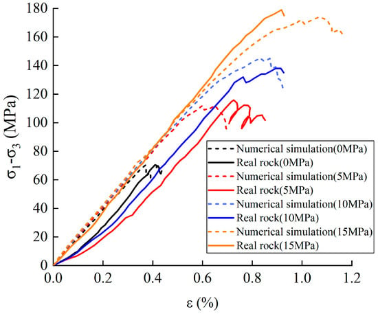
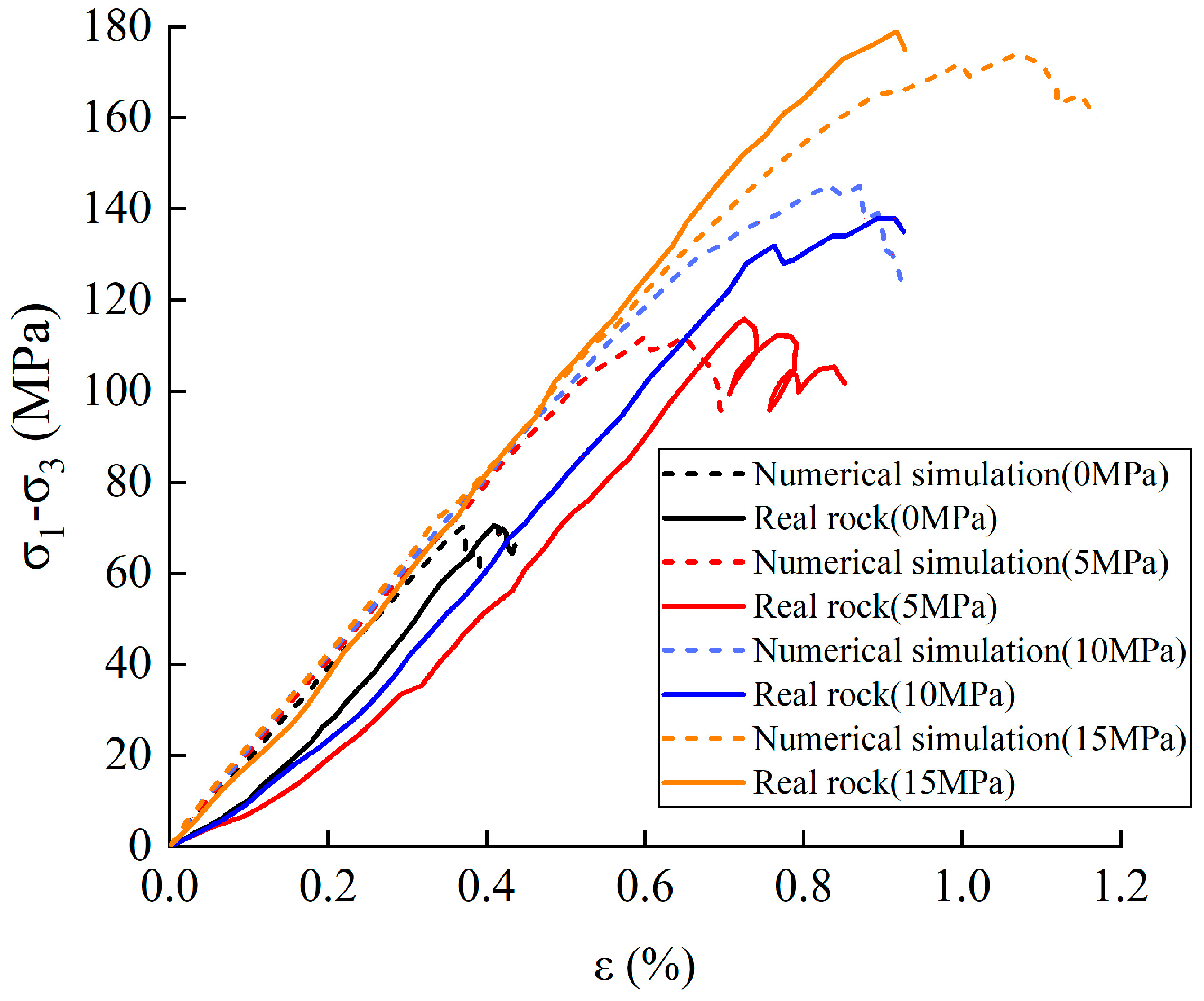
The trial-and-error method was applied to calibrate the mesoscopic parameters of the parallel-bond contact model in this work. The macroscopic elastic modulus, Poisson’s ratio, cohesion and internal friction angle rise with the increase in contact modulus, stiffness ratio, bond strength and parallel-bond friction angle. Mesoscopic parameters were adjusted repeatedly to make the macroscopic mechanical properties acquired from numerical simulation consistent with laboratory test results. Finally, a set of parallel-bond mesoscopic parameters that can well represent the macroscopic mechanical behaviors of immediate roof rock were determined, and these parameter values are listed in Table 1. For specimens with diverse strengths in the calibration process, variations in macroscopic strength were realized chiefly by modifying the bond-breakage threshold between particles. The mesoscopic parameters governing mechanical responses and particle fabric remained unchanged. Consequently, no unexpected obvious variations occurred in the elastic modulus, Poisson’s ratio and fundamental failure modes. The stress–strain curves obtained from numerical simulation and laboratory tests are presented in Figure 1. The relative errors of macroscopic mechanical parameters including elastic modulus and Poisson’s ratio were quantified (Table 2). The results demonstrate that the relative error of every macroscopic mechanical parameter is less than 3%. In addition, the failure patterns of simulated specimens basically agree with laboratory observations. It verifies that the selected parallel-bond mesoscopic parameters can faithfully reproduce the macroscopic-mechanical behaviours of the real rock mass.
Table 1.
Mesoscopic parameters of parallel bond.
Figure 1.
Stress−strain curves of rock specimens from simulation and laboratory tests under different confining pressures.
Table 2.
Comparison between numerical simulation and laboratory test results.
2.3. Numerical Simulation Process and Scheme
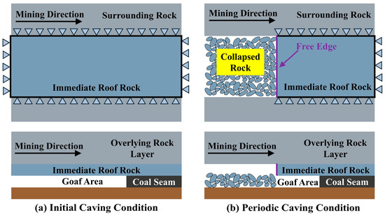
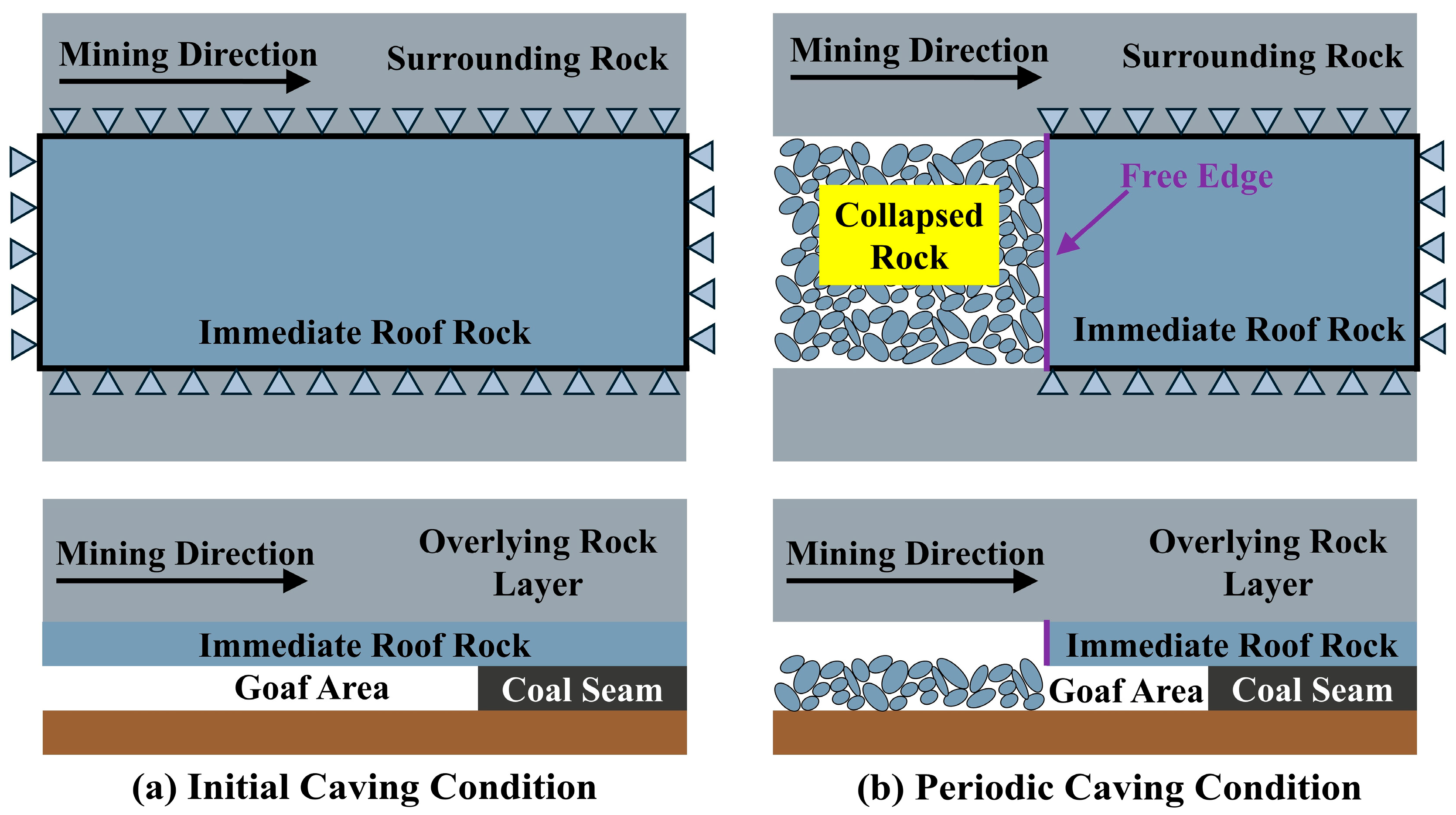
In this paper, the boundary conditions of four-sided fixed support and three-sided fixed support with one free side are set via the numerical-simulation approach to reproduce initial caving and periodic caving in the mining process, respectively (Figure 2). A set of parameters including damping coefficient and wall-particle contact friction adopted in the numerical simulation are listed in Table 3. This study mainly investigates how geometric parameters, unloading stress and specimen strength affect the unloading-induced fracture characteristics of immediate roof rock under different boundary conditions. To guarantee comparability among various working-condition groups, models with identical dimensions are assigned the same random seed and porosity for generating particle fabric. This measure minimizes the influence of randomly generated particles on comparative analysis across working conditions. All established numerical-simulation models possess a uniform width of 125 mm, and the numerical-simulation schemes are summarized in Table 4.
Figure 2.
Schematic diagram of mechanical-loading models for initial caving and periodic caving.
Table 3.
Model parameter settings.
Table 4.
Numerical Simulation Test Scheme.
A numerical simulation model is established according to the laboratory test results, and the relevant mesoscopic parameters are given as follows:
- Generate a cuboid model with the size specified in the test scheme in PFC3D, and use the expand command to prevent particle overflow in subsequent calculations;
- To achieve a more uniform distribution of the force chain among generated particles, the brick command is used to generate particles in a region with similar length, width and thickness. After model equilibrium, the brick assemble command is adopted to generate particles uniformly in the X and Y planes (For instance, the model with specimen dimensions of 565 × 165 × 20 mm contains 72332 particles in total and possesses 221588 contact pairs);
- After model equilibrium, the calibrated mesoscopic parameters are assigned to the model to implement cementation;
- Delete the upper and lower wall facets of the model, and generate rectangular frame walls at the original positions, as well as a rigid unloading wall at the bottom and shell elements at the top to simulate flexible loading;
- Apply boundary conditions and stress to the shell elements. Meanwhile, the wall-delete command is adopted to simulate the unloading process;
- Terminate the calculation program when the displacement of the lower rigid unloading wall reaches 10 mm, and then perform statistical analysis on the simulation results.
Under the above-mentioned computing platform and calculation conditions, the actual runtime for each working condition is approximately 7–8 h. The runtime presented in this paper is mainly used to characterize the computational cost of the numerical model.
3. Research on Unloading Fracture Characteristics of Immediate Roof Rock in Stope
3.1. Fractal Characteristics of Fragment Gradation for Immediate Roof Rock Under Unloading Fracture
3.1.1. Initial Caving Stage
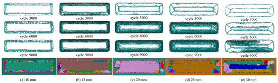
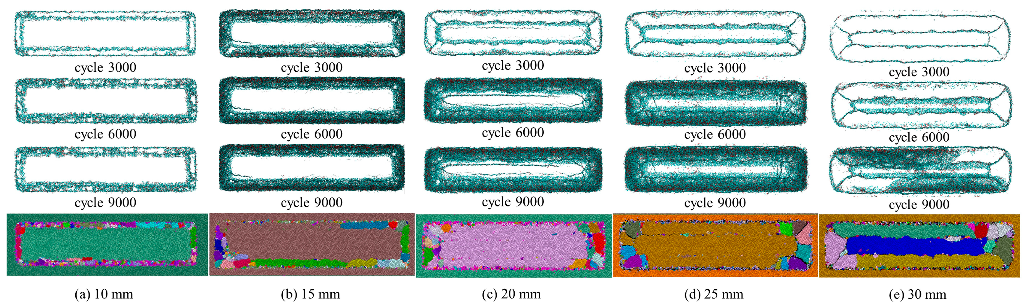
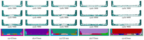
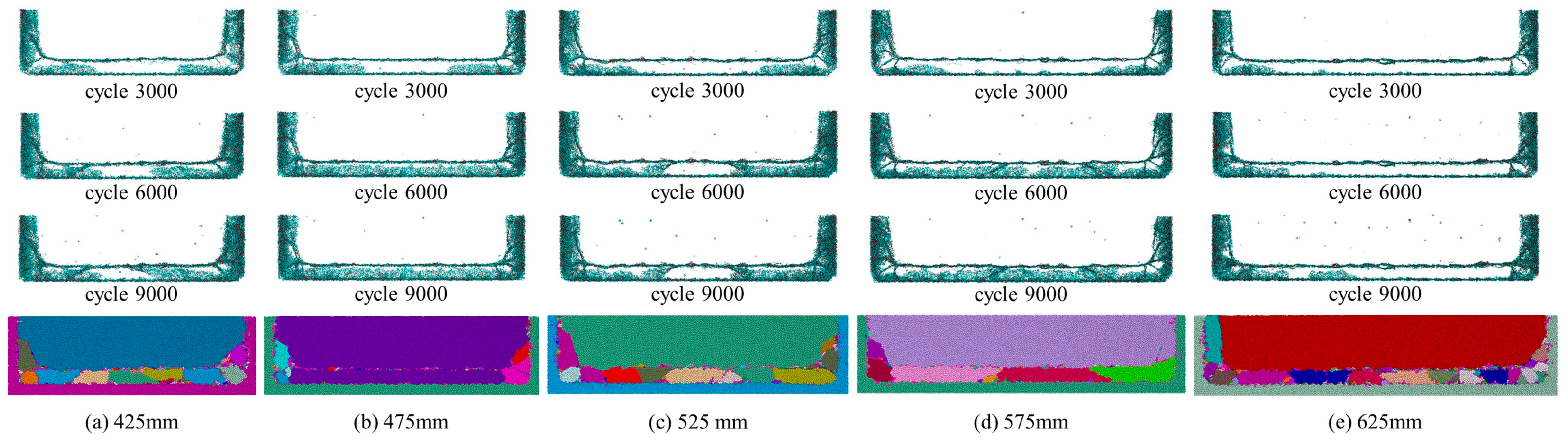
A four-sided fixed numerical simulation model is established according to the designed dimensions of the test scheme to simulate the initial caving behavior of immediate roof rock. Under the condition of initial caving, the development and propagation of internal cracks and rigid unloading surfaces of specimens with different thickness-width ratios during unloading and fracturing are shown in Figure 3. It can be seen from the figure that rectangular punching cracks appear inside the 10 mm thick specimen at the initial unloading stage (Figure 3a). The cracks of the 15 mm thick specimen (Figure 3b) tend to develop toward the central region. As the specimen thickness increases to 20 mm (Figure 3c), obvious O-X type cracks emerge at the initial unloading stage. When the specimen thickness reaches 25 mm (Figure 3d), the cracks developed at the four-sided fixed supports change from rectangular to elliptical. For the 30 mm thick specimen (Figure 3e), the particle size of fractured blocks formed by crack propagation and penetration further increases.
Figure 3.
Development and propagation of rigid unloading surface and internal cracks of specimens with different thickness-width ratios under initial caving.
The development and propagation of rigid unloading surfaces and internal cracks of specimens with different length-width ratios under initial caving are shown in Figure 4. It can be observed that obvious O-X tensile cracks develop in all specimens at the initial stage of unloading failure for various length-width ratios. The X-shaped tensile cracks at the left and right ends of each specimen further propagate and evolve, forming a radial crack network. Combined with the failure characteristics of the rigid unloading surface, the horizontally developed tensile cracks in the central region of the specimens do not penetrate the upper and lower surfaces, indicating that failure is mainly concentrated in the left and right end regions. The above results demonstrate that the length-width ratio has no significant influence on the crack morphology of specimen fragmentation, and the failure mode, failure process and rigid unloading surface damage characteristics of specimens with different length-width ratios are basically consistent.
Figure 4.
Development and propagation of rigid unloading surface and internal cracks of specimens with different length-width ratios under initial caving.
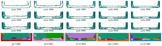
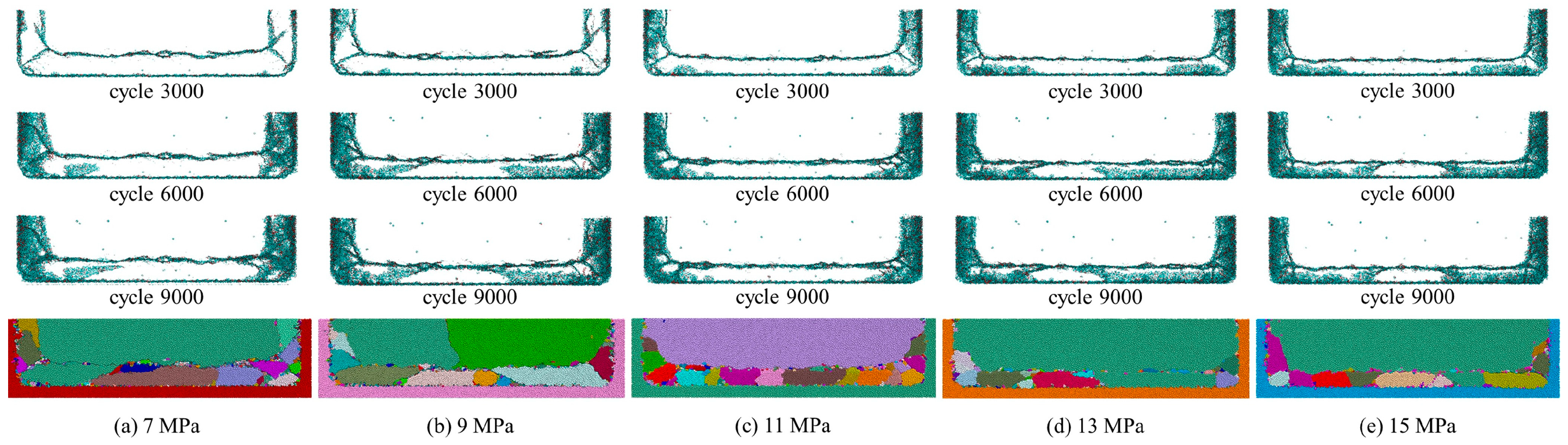
The development and propagation of rigid unloading surfaces and internal cracks of specimens under different unloading stresses during initial caving are presented in Figure 5. It can be seen that specimens under an unloading stress of 7 MPa (Figure 5a) exhibit obvious O-X type cracks inside. When the unloading stress increases to 9 MPa (Figure 5b), the tensile cracks are distributed relatively uniformly within the specimen. As the unloading stress rises to 11 MPa (Figure 5c), the X-shaped cracks at both ends expand rapidly and form a crack network. For the specimen under 13 MPa unloading stress (Figure 5d), only a small part of the horizontally developed tensile cracks in the central region penetrate the upper and lower surfaces. When the unloading stress reaches 15 MPa (Figure 5e), none of the horizontal tensile cracks in the specimen center penetrate the upper and lower surfaces, and the initiation and concentration zones of failure are located at both ends of the specimen.
Figure 5.
Development and propagation of rigid unloading surface and internal cracks of specimens with different unloading stresses under initial caving.
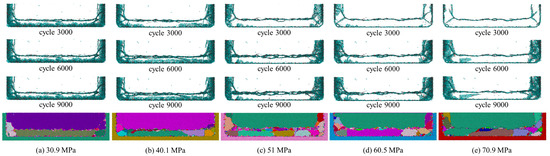
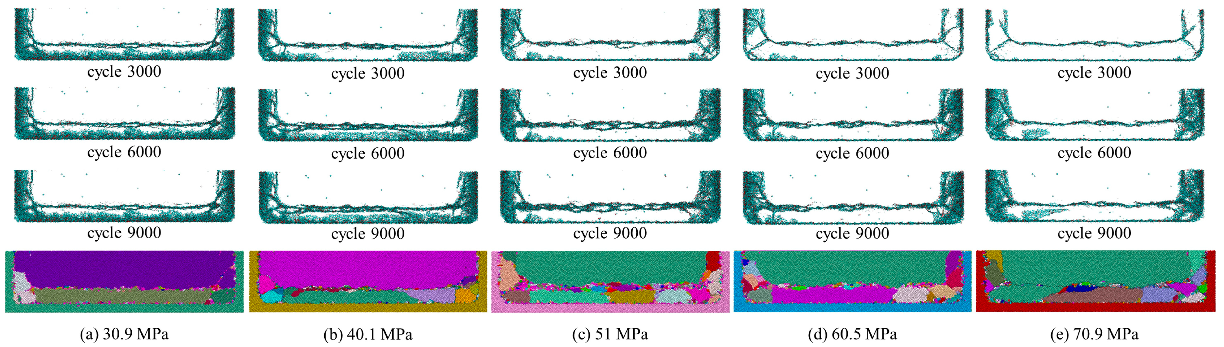
The development and propagation of rigid unloading surfaces and internal cracks of specimens with different strengths under initial caving are shown in Figure 6. It can be observed that the peripheral area of the specimen with a strength of 30.9 MPa (Figure 6a) is fully covered by obliquely developed cracks. When the strength increases to 40.1 MPa (Figure 6b), the oblique tensile cracks are in the stage of development and propagation but do not completely cover the peripheral region. As the strength rises to 51 MPa (Figure 6c), the O-X tensile cracks of the specimen develop obviously. The specimen with a strength of 60.5 MPa (Figure 6d) presents a more uniform overall failure, while the failure intensity decreases to some extent. When the strength reaches 70.9 MPa (Figure 6e), the region between the two horizontal tensile cracks of the specimen is still not completely covered by tensile-shear cracks.
Figure 6.
Development and propagation of rigid unloading surface and internal cracks of specimens with different strengths under initial caving.
Macro fractured rock blocks are composed of small fractured fragments, and these small fragments are further generated by the development and coalescence of microcracks. This feature endows the fragment size distribution of broken rock with obvious self-similarity [24]. Based on this characteristic, the particle size-mass fractal dimension D is introduced in this study. According to the fractal theory of fractured rock [25], the relationship between the mass of fractured rock blocks and the total mass of rock specimens can be expressed by Equation (1):
where Md is the cumulative mass of fragments with particle size smaller than d, kg; Mt is the total mass of the fractured specimen, kg; dmin is the minimum particle size of fractured blocks, mm; dM is the maximum particle size of fractured blocks, mm; d is the particle size of fractured blocks, mm; and D is the particle size-mass fractal dimension. Owing to the grinding effect between broken blocks in the test, debris particles with extremely small particle-sizes are produced. The particle-size of these debris particles can be approximated to zero, and Equation (1) can therefore be simplified as:
By taking the logarithm of both sides of the equation, the above-mentioned formula can be transformed into:
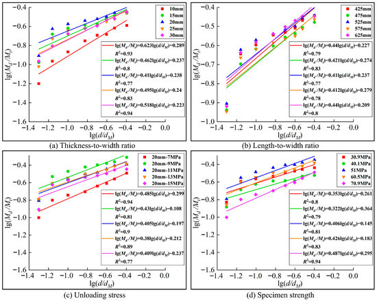
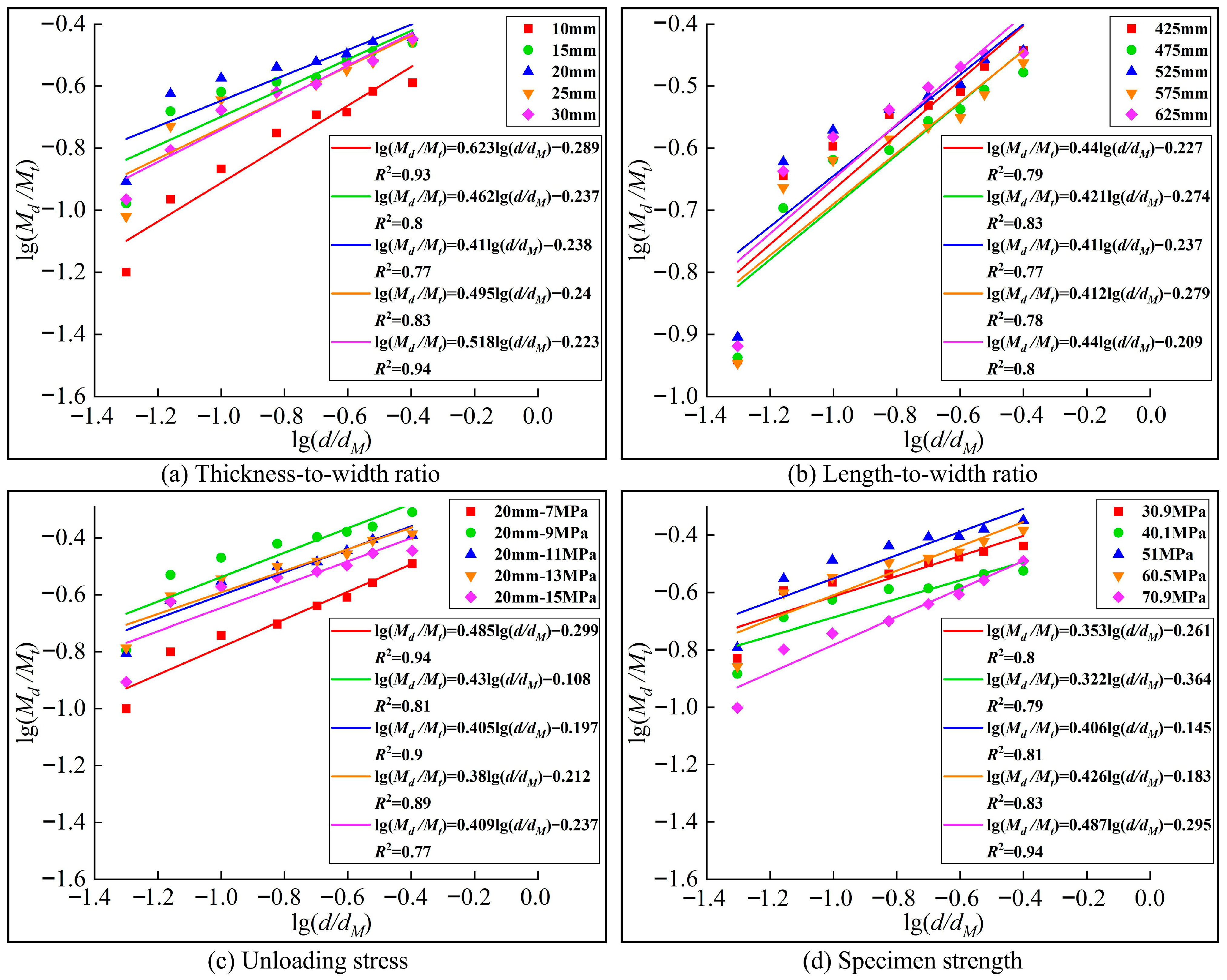
The block size statistics of broken specimens are carried out by the equivalent volume method. The particle-size is determined by equating the specimen volume to that of an equivalent sphere. Before unloading initiation, the PFC3D file is invoked to monitor the inter-particle contact state in real-time, and broken blocks are automatically classified into different fragments. The total mass of each fragment is acquired by traversing the mass of constituent particles. The fragment volume can be calculated by dividing its total mass by the preset sphere density. Afterwards, the equivalent particle-size is solved on the basis of the spherical-volume assumption. Finally, a self-compiled particle-size classification and statistics program is adopted to compute the mass of fragments whose particle-sizes are less than 5 mm, 7 mm, 10 mm, 15 mm, 20 mm, 25 mm, 30 mm and 40 mm. Combined with the above Equation (3), the values of lg(Md/Mt) and lg(d/dM) of broken specimens are calculated, and the scatter plot of lg(Md/Mt) versus lg(d/dM) is plotted for linear fitting. The fitting curves are shown in Figure 7. As can be observed from the figure, despite disparities in fitting quality for different working-condition groups over the selected scale interval, all cases yield approximate correlations to varying extents. This demonstrates that the grain-size distribution of broken fragments of the specimen exhibits a certain level of self-similarity. Moreover, the slope of the fitted straight line is directly correlated with the particle size–mass fractal dimension. A larger slope corresponds to a smaller fractal dimension, which means a higher proportion of large-size fragments after failure; conversely, a greater fractal dimension represents more intense fragmentation and a higher proportion of fine particles.
Figure 7.
lg(Md/Mt)−lg(d/dM) Curves of unloading fracture fragments of immediate roof rock during initial caving.
3.1.2. Periodic Caving Stage
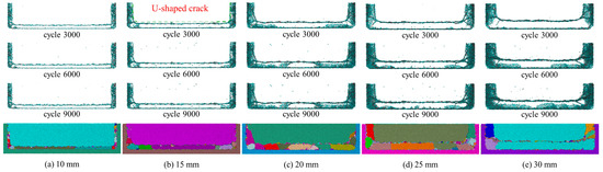
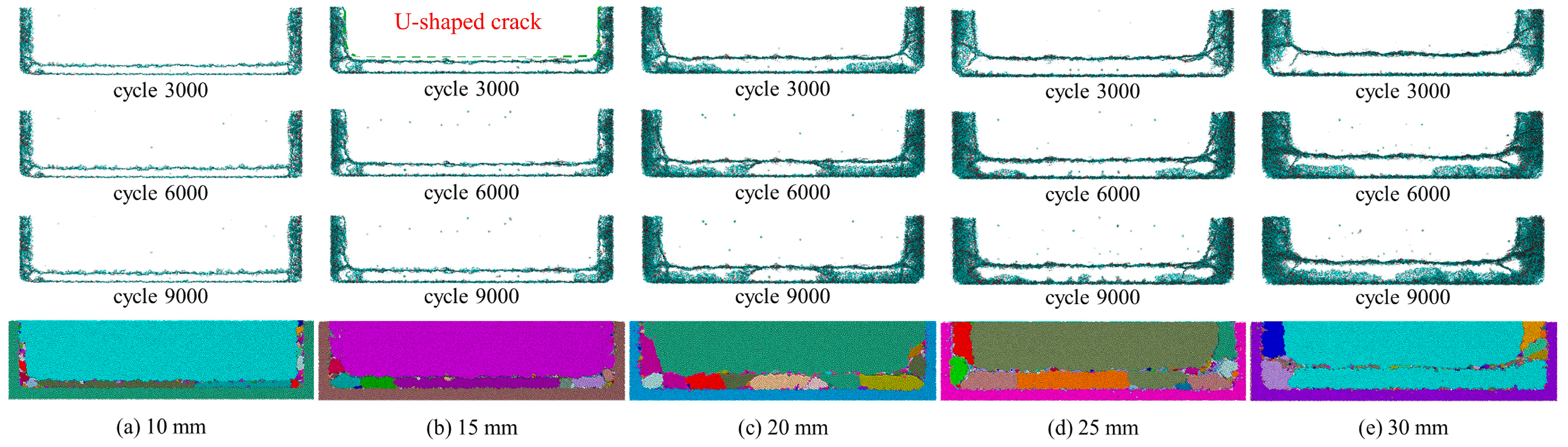
A numerical simulation model with three sides fixed and one side free is established according to the designed dimensions of the test scheme to simulate the periodic caving behavior of immediate roof rock. Under periodic caving conditions, the development and propagation of rigid unloading surfaces and internal cracks of specimens with different thickness-width ratios during unloading fracturing are shown in Figure 8. It can be seen that cracks develop densely at the fixed supports on both ends of the 10 mm thick specimen (Figure 8a). As the specimen thickness increases to 15 mm (Figure 8b), U-shaped cracks appear near the fixed support at the lower end. For the 20 mm thick specimen (Figure 8c), the inclined cracks at the lower fixed support propagate and evolve into U-shaped cracks. The U-shaped cracks produce extended branches at both ends of the 25 mm thick specimen (Figure 8d). The tensile-shear cracks at the left and right ends of the 30 mm thick specimen (Figure 8e) are still in the developing stage.
Figure 8.
Development and propagation of rigid unloading surface and internal cracks of specimens with different thickness-width ratios under periodic caving.
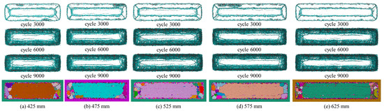
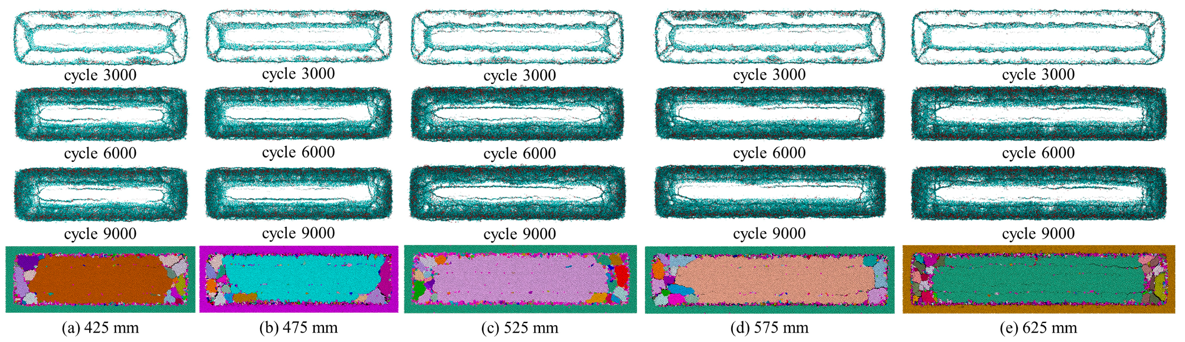
The development and propagation of rigid unloading surfaces and internal cracks of specimens with different length-width ratios under periodic caving are illustrated in Figure 9. Combined with the failure characteristics of the rigid unloading surface, the initiation positions of U-shaped cracks in all specimens are basically at the same distance from the fixed ends. The failure is mainly concentrated in the vicinity of the fixed boundaries of the specimens. In the early failure stage, a large number of dense cracks and damage rapidly emerge near the left and right fixed ends, followed by gradual slow crack initiation and failure development at the lower fixed end.
Figure 9.
Development and propagation of rigid unloading surface and internal cracks of specimens with different length-width ratios under periodic caving.
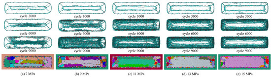
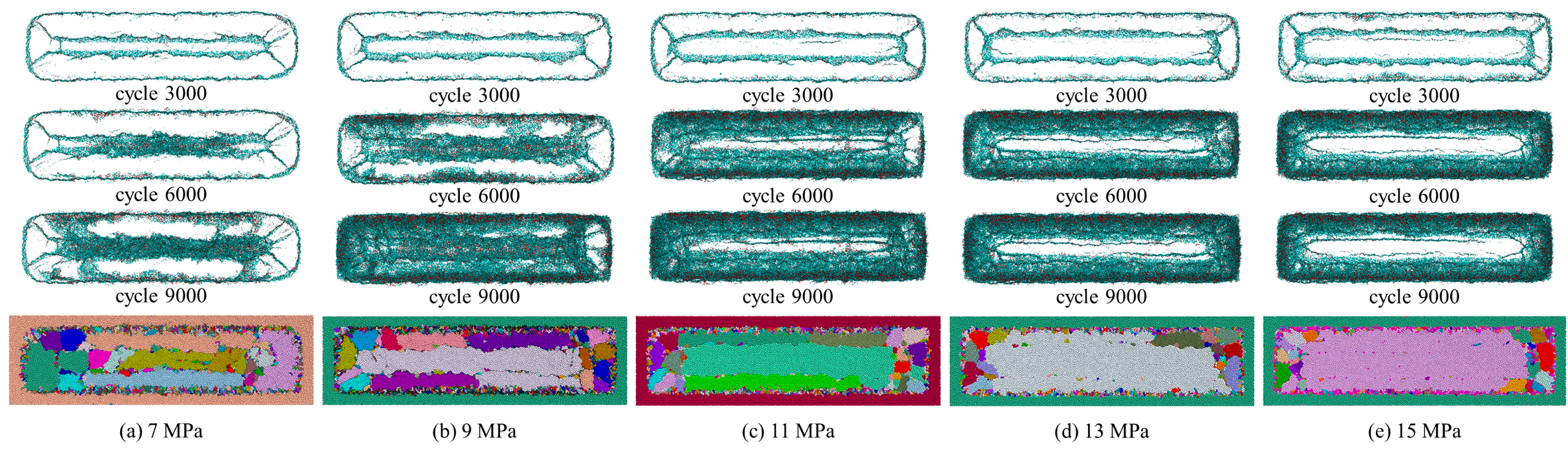
The development and propagation of rigid unloading surfaces and internal cracks of specimens under different unloading stresses during periodic caving are shown in Figure 10. It can be seen that a small number of inclined tensile cracks develop at the lower end of U-shaped cracks for the specimen under an unloading stress of 7 MPa (Figure 10a). Under the unloading stress of 9 MPa (Figure 10b), a large number of inclined tensile cracks are fully developed at the lower end of the specimen. When the unloading stress is 11 MPa (Figure 10c), large-scale cracks firstly appear in the left and right end regions of the specimen. As the unloading stress increases to 13 MPa (Figure 10d), the area of the square region enclosed by U-shaped cracks expands obviously. For the specimen under 15 MPa unloading stress (Figure 10e), the number of penetrating crack branches at both left and right ends of U-shaped cracks increases significantly.
Figure 10.
Development and propagation of rigid unloading surface and internal cracks of specimens with different unloading stresses under periodic caving.
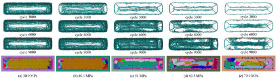
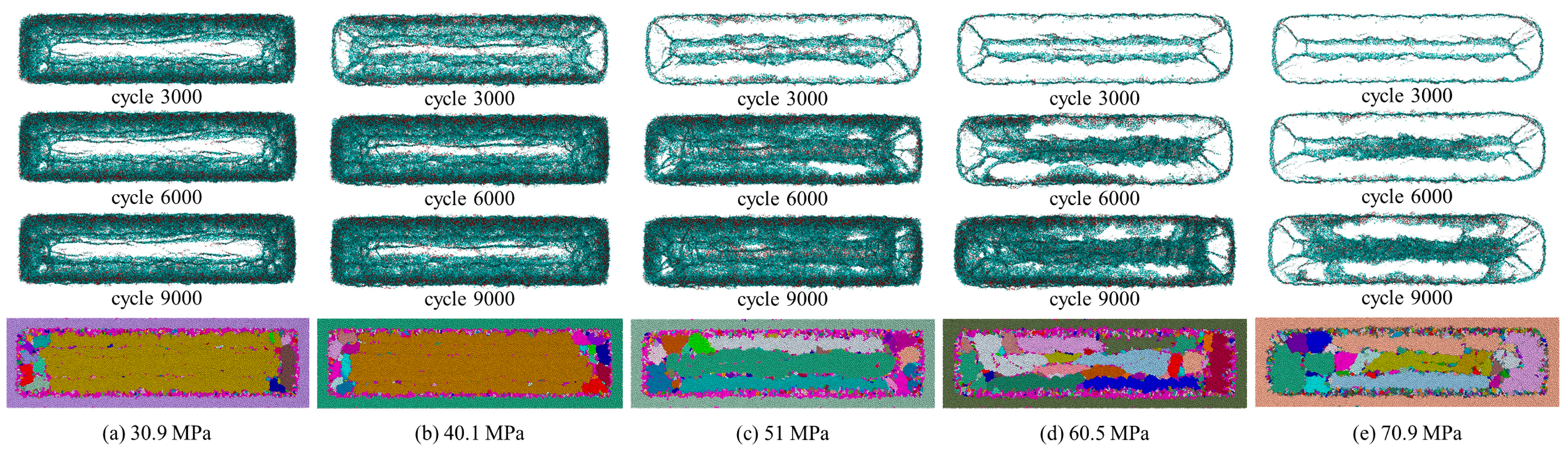
The development and propagation of rigid unloading surfaces and internal cracks of specimens with different strengths under periodic caving are shown in Figure 11. It can be seen that U-shaped cracks are formed inside the specimen with a strength of 30.9 MPa (Figure 11a). A large number of dense tensile-shear cracks generate at the left and right ends of the specimen when the strength reaches 40.1 MPa (Figure 11b). Partial cracks at the lower end expand in a spiral pattern at the strength of 51 MPa (Figure 11c). For the specimen with a strength of 60.5 MPa (Figure 11d), the development rate of tensile-shear cracks at the left and right ends slows down at the initial unloading stage. When the specimen strength increases to 70.9 MPa (Figure 11e), the failure initiates from the left and right end regions and concentrates near the three fixed supports of the specimen.
Figure 11.
Development and propagation of rigid unloading surface and internal cracks of specimens with different strengths under periodic caving.
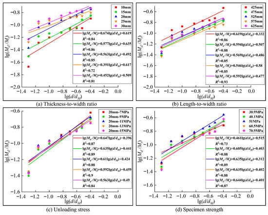
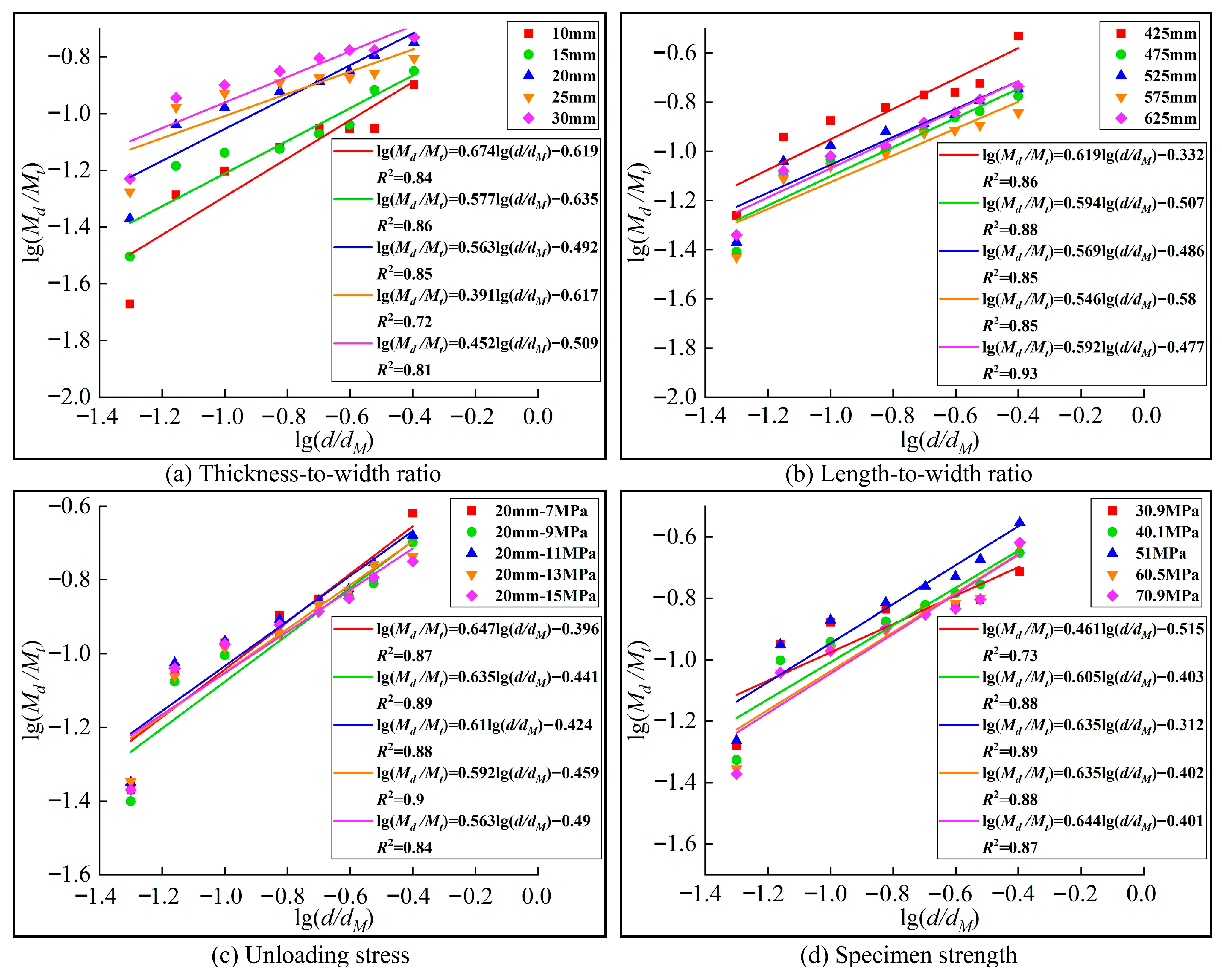
Statistical fitting of the broken specimens was carried out using the statistical method described above, and the fitting results are presented in Figure 12. A certain degree of self-similar evolutionary characteristics can be identified from the fitting results.
Figure 12.
lg(Md/Mt)−lg(d/dM) Curves of unloading fracture fragments of immediate roof rock under periodic caving.
3.2. Morphological Characteristics of Unloading Fracture Fragments of Immediate Roof Rock
3.2.1. Initial Caving Stage
The morphological characteristics of fractured blocks are classified according to the value range of the length-thickness ratio, with the definitions as follows [26]:
- Block-Strip fragments, length-thickness ratio ∈ (1,3);
- Strip-Slab fragments, length-thickness ratio ∈ (3,6);
- Plate-Sheet fragments, length-thickness ratio ∈ (6,9);
- Flake fragments, length-thickness ratio ∈ (9,+∞).
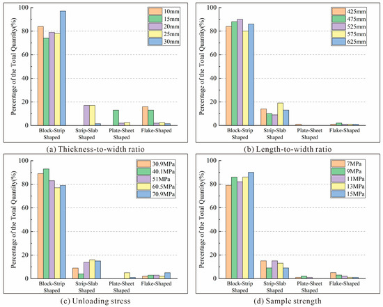
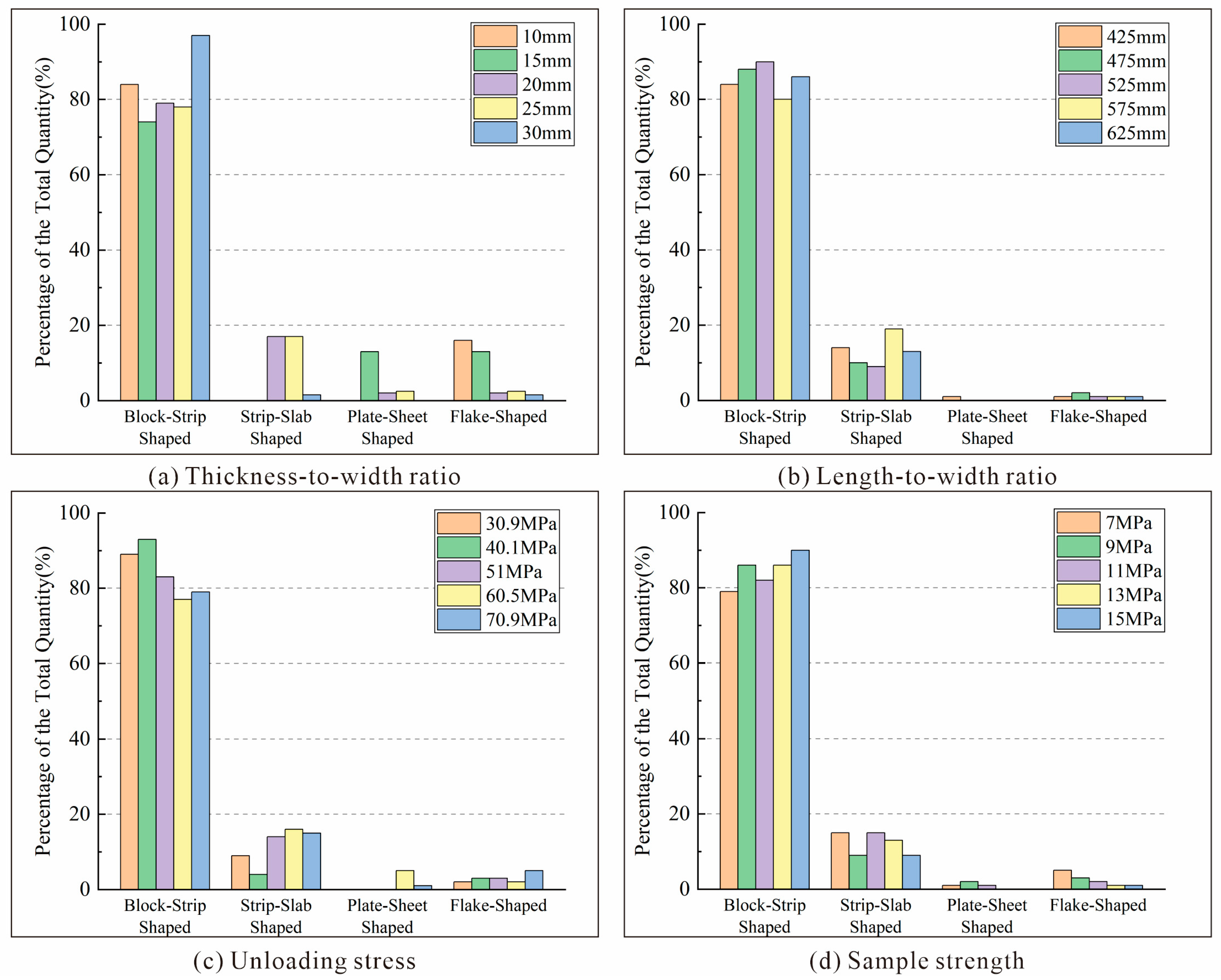
Based on the length-thickness ratio, the fragment morphological characteristics of immediate roof rock during initial caving under different thickness-width ratios, length-width ratios, unloading stresses and rock strengths are plotted in Figure 13. It can be observed that under the initial caving condition, the morphological distribution of broken fragments for specimens with different thickness-width ratios follows the order: Block-Strip > Strip-Slab > Plate-Sheet + Flake; the distribution law for specimens with different length-width ratios is Block-Strip > Strip-Slab > Plate-Sheet + Flake; specimens under different unloading stresses also present the same distribution order of Block-Strip > Strip-Slab > Plate-Sheet + Flake; similarly, specimens with different rock strengths follow the distribution characteristic of Block-Strip > Strip-Slab > Plate-Sheet + Flake.
Figure 13.
Percentage of fragment morphology in total fragment number of immediate roof rock under initial caving.
3.2.2. Periodic Caving Stage
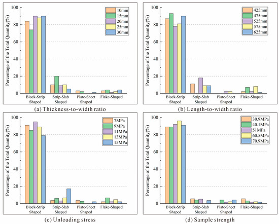
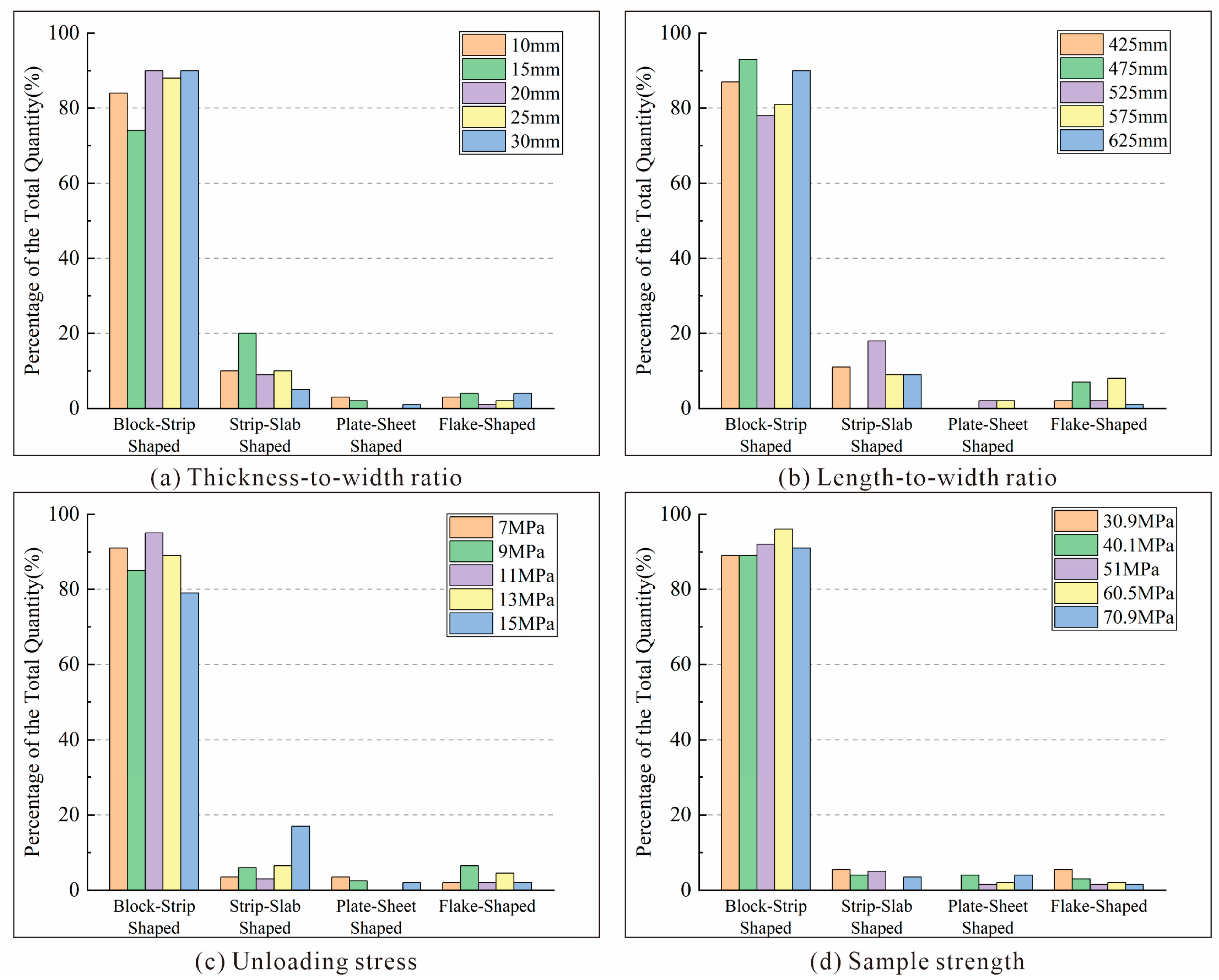
The fragment morphological characteristics of immediate roof rock under periodic caving with different thickness-width ratios, length-width ratios, unloading stresses and rock strengths are statistically analyzed by the above method, and the results are shown in Figure 14. The results indicate that under periodic caving conditions, the broken fragments of specimens with different thickness-width ratios are mainly dominated by Block-Strip; the morphological distribution of broken fragments of specimens with different length-width ratios basically follows the order of Block-Strip > Strip-Slab > Flake + Plate-Sheet; the fragment distribution of specimens under different unloading stresses presents the order of Block-Strip > Strip-Slab > Flake > Plate-Sheet; specimens with different strengths show basically the same morphological distribution, namely Block-Strip > Strip-Slab + Flake + Plate-Sheet.
Figure 14.
Percentage of fragment morphology in total fragment number of immediate roof rock under periodic caving.
3.3. Fractal Characteristics of Unloading Fracture Cracks of Immediate Roof Rock
3.3.1. Initial Caving Stage
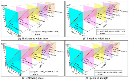
Previous scholars have introduced fractal geometry theory into the field of rock-soil mechanics. The fractal dimension is adopted to quantify the complexity of internal cracks inside fractured rock. Existing studies have proven that the crack distribution within rock masses presents prominent self-similarity [27]. This paper focuses on how different parameters affect the crack-evolution law on the unloading surface during the unloading of the immediate roof. Since the unloading surface acts as the most active zone for crack initiation, propagation and coalescence, two-dimensional crack nephograms are employed to characterize the overall fracture network inside the rock mass. In this paper, the box-counting dimension method is adopted to quantitatively characterize the crack characteristics of specimens. The fracture plane of the broken specimen is covered by square grids with side length a, and the number of grids containing cracks is counted. By continuously reducing the grid side length a, the crack fractal dimension D′ is calculated according to the variation in the number of crack-containing grids, which can be expressed by Equation (4):
where a is the side length of the square grid, mm; and N is the number of grids covering cracks under the current grid size.
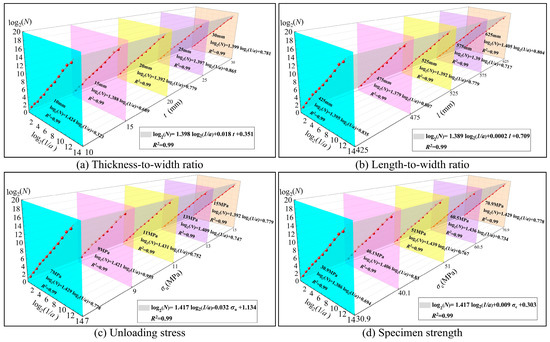
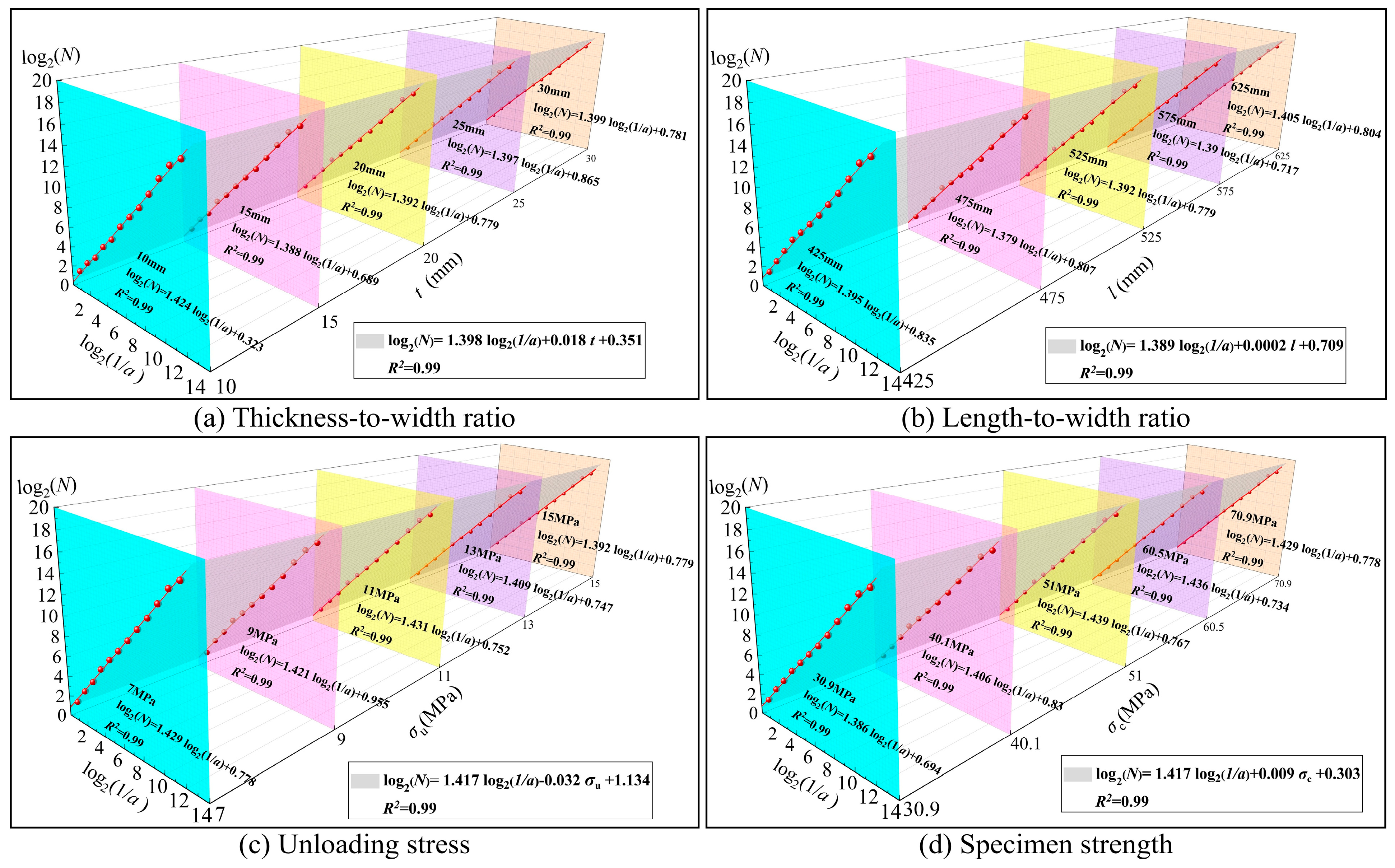
The sketch method is adopted to depict the cracks on rigid unloading surfaces of immediate roof rock during initial caving under different thickness-width ratios, length-width ratios, unloading stresses and rock strengths. Furthermore, MATLAB R2025b is adopted to perform the box-counting-based fractal dimension computation for cracks on the rigid unloading surface [28,29], and the fitting results are shown in Figure 15. It can be seen that the fitting curves under each working condition present an excellent fitting effect, with all the coefficient of determination R2 greater than 0.99. This indicates that the crack development degree of broken rock samples exhibits extremely high self-similarity.
Figure 15.
Fitting diagram of fractal dimension of unloading fracture cracks of immediate roof rock during initial caving.
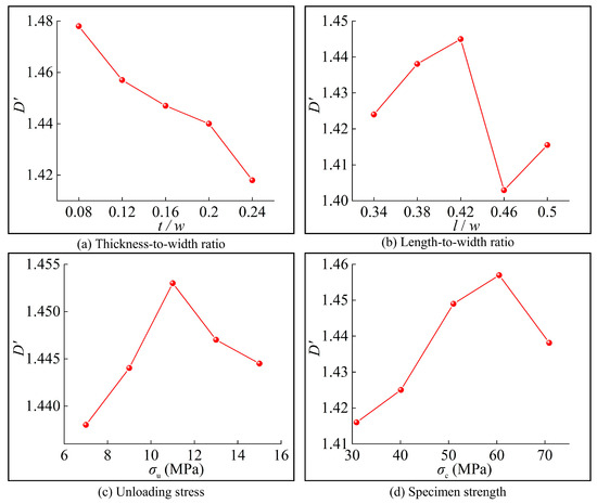
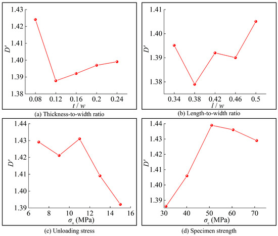
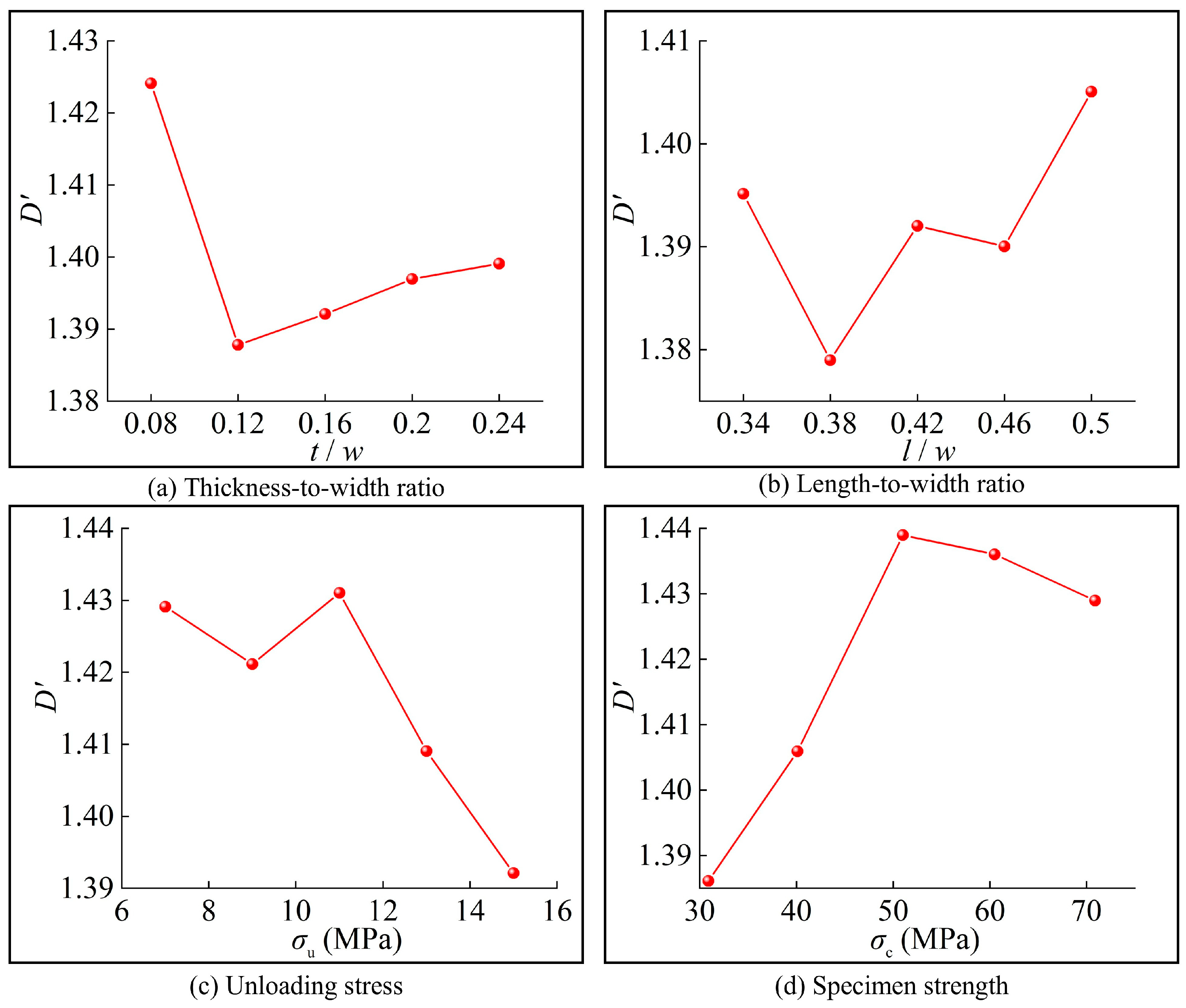
Combined with Equation (4), the crack fractal dimension of the rigid unloading surface of broken specimens is calculated. The relationship curves between the crack fractal dimension of rigid unloading surface and specimen thickness-width ratio, specimen length-width ratio, unloading stress as well as specimen strength are plotted in Figure 16. The results show that under the initial caving condition, the crack fractal dimension of the unloading surface of immediate roof rock decreases monotonously with the increase in thickness-width ratio; it presents an evolutionary characteristic of increasing first, then decreasing and finally increasing with the rise in length-width ratio. In addition, the fractal dimension shows a trend of increasing first and then decreasing with the growth of both unloading stress and specimen strength.
Figure 16.
Relationship between crack fractal dimension and thickness-width ratio, length-width ratio, unloading stress as well as specimen strength of immediate roof rock under initial caving.
3.3.2. Periodic Caving Stage
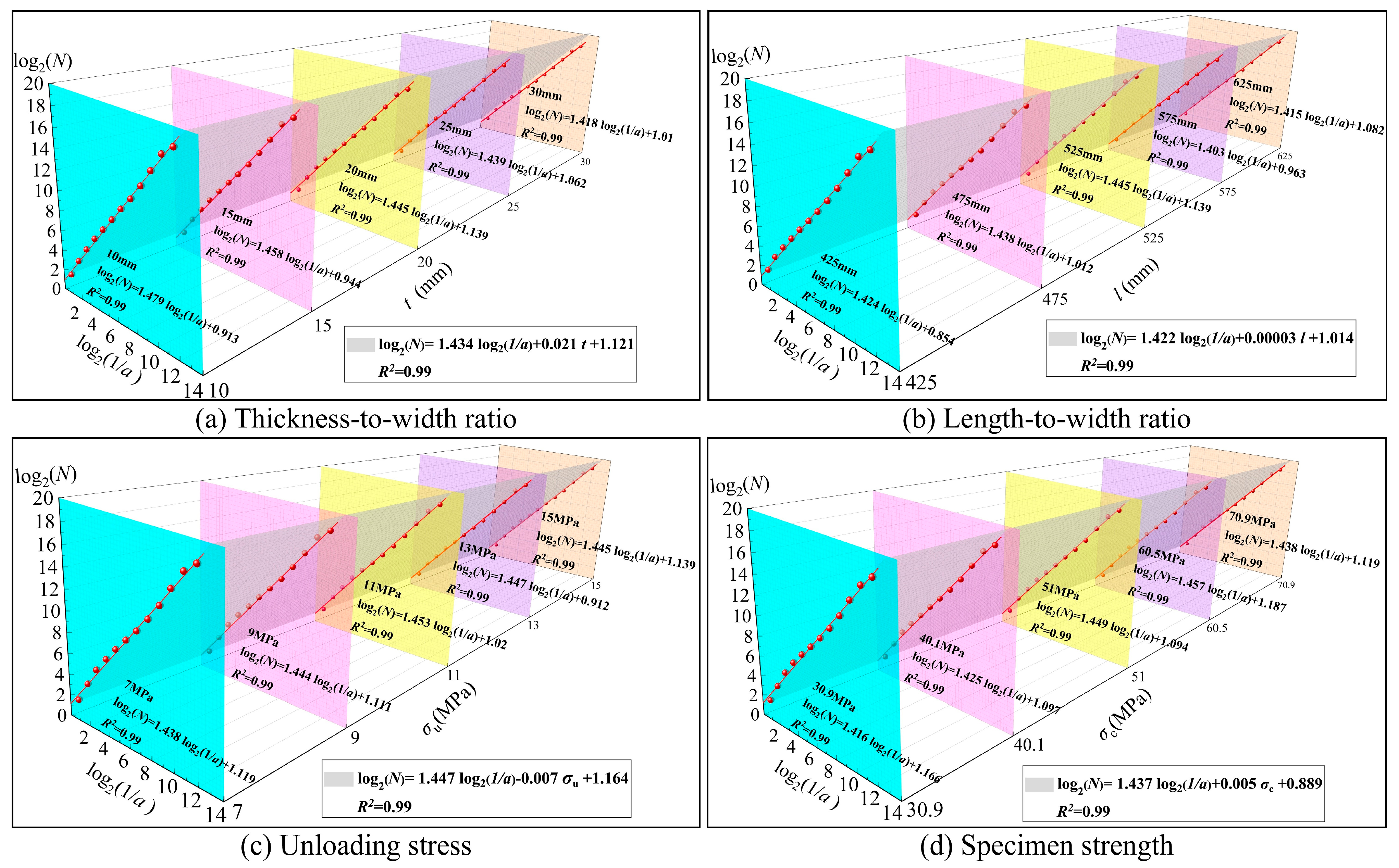
The two-dimensional fractal dimension of crack patterns was calculated using the above method, and the fitting results are shown in Figure 17. It can be seen that the fitting curves under all working conditions exhibit excellent fitting performance, with the coefficient of determination R2 all greater than 0.99. This indicates that the crack development of broken rock specimens possesses extremely high self-similarity.
Figure 17.
Fitting diagram of fractal dimension of unloading fracture cracks of immediate roof rock during periodic caving.
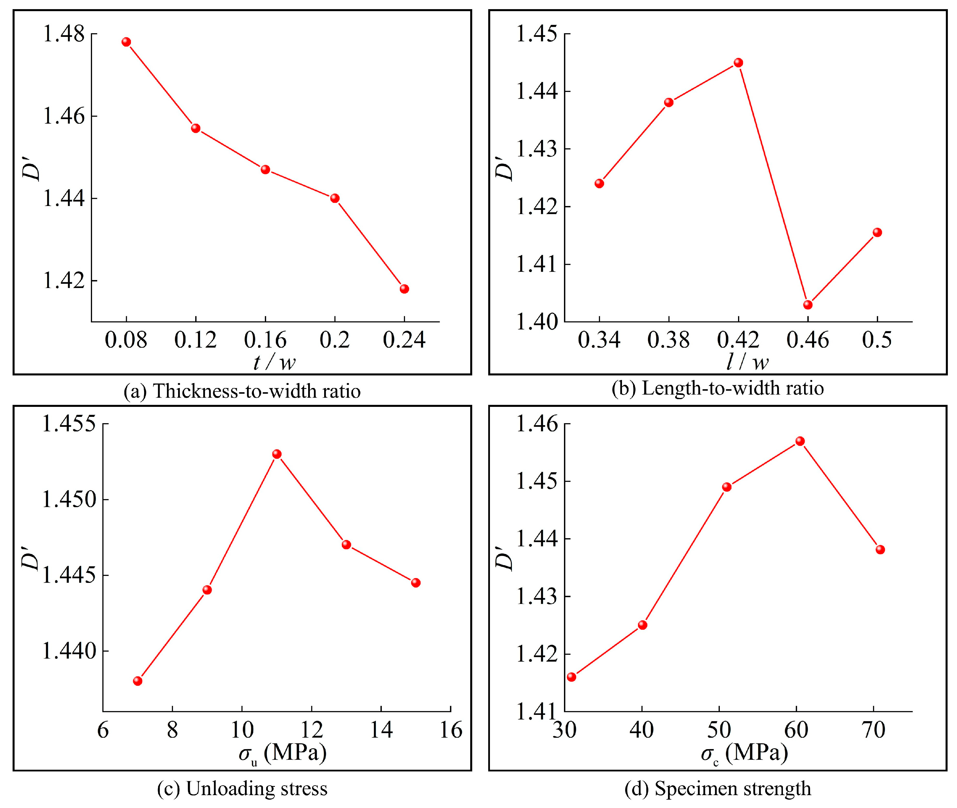
According to the aforementioned method, the relationship curves between the crack fractal dimension on the rigid unloading surface of broken specimens and the thickness-width ratio, length-width ratio, unloading stress as well as specimen strength are plotted in Figure 18. It can be seen that under periodic caving conditions, the crack fractal dimension of the unloading surface of immediate roof rock shows a trend of decreasing first and then increasing with the rise in thickness-width ratio. With the increase in unloading stress and specimen strength, it both presents an evolutionary characteristic of increasing first and then decreasing. In contrast, the variation range of the crack fractal dimension on the unloading surface of specimens with different length-width ratios is relatively small.
Figure 18.
Relationship between crack fractal dimension and thickness-width ratio, length-width ratio, unloading stress and specimen strength of immediate roof rock under periodic caving.
4. Mechanism Analysis of Influencing Factors on Unloading Fracture Characteristics of Immediate Roof Rock
4.1. Analysis on Influence Mechanism of Thickness-Width Ratio
To better describe the fracture characteristics of specimens, the average particle size dm is introduced herein:
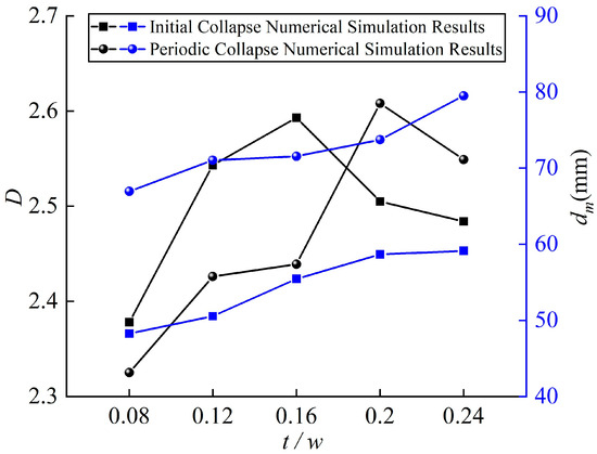
where dm is the average fragment particle size of each mass distribution interval, mm; and ri is the mass fraction of rock fragments in each distribution interval. According to Equations (3) and (5), the particle-size-mass fractal dimension and average particle size of broken blocks with different thickness-width ratios are calculated. The relationships between grain-mass fractal dimension, average particle size and thickness-width ratio of immediate roof rock under initial caving and periodic caving are respectively fitted, and the fitting results are shown in Figure 19. It can be seen that under both initial caving and periodic caving conditions, the particle-size-mass fractal dimension of broken fragments of immediate roof rock presents a trend of rising first and then declining with the increase in thickness-width ratio, while the average particle size increases monotonously and gradually tends to be stable as the thickness-width ratio rises.
Figure 19.
Relationship between particle-size-mass fractal dimension, average particle size and specimen thickness-width ratio.
The thickness-width ratio affects the flexural rigidity and failure mode of immediate roof rock. Based on the rock-beam block theory, Chen et al. [30] pointed out that the failure pattern of immediate roof rock can gradually transform from flexural failure to overall caving and arch-shaped caving with the increase in roof thickness, indicating that variations in roof geometric characteristics can induce adjustments in the bearing mechanism and macroscopic failure mode. Under the particle fabric and parameter conditions adopted in this study, specimens with a small thickness-width ratio exhibit low flexural rigidity. The bending deformation concentrates limited energy in the tensile zone, whereby cracks easily penetrate the thin rock layer and yield a small particle size of fragments. As the thickness-width ratio increases, the stress distribution inside the rock becomes more uniform, the tension-shear failure is enhanced, and cracks develop more fully with a higher penetration degree. The elastic strain energy stored in the rock mass rises, tension-shear cracks propagate cooperatively, and more energy is dissipated in the generation of micro-cracks and new fracture surfaces, which leads to an increase in the particle-size–mass fractal dimension. With the further increase in the thickness-width ratio, the failure of immediate roof rock undergoes a staged transition from local failure and sufficient crack development to dominant-crack-controlled failure. Energy concentrates and releases rapidly along the dominant shear band, the energy-dissipation proportion of secondary cracks decreases, and the failure transforms into shear instability. Consequently, crack development is restrained and the fragmentation degree is weakened, manifested as a reduction in the particle-size–mass fractal dimension and an increase in the particle size of fragments.
4.2. Analysis on Influence Mechanism of Length-Width Ratio
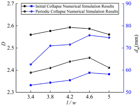
Based on the aforementioned method, the particle-size-mass fractal dimension and average particle-size of broken fragments under various length-width ratios are calculated. Fitting analyses are conducted on the relationships among the length-width ratio, particle-size-mass fractal dimension and average particle-size of immediate-roof rock under initial caving and periodic caving conditions, and the outcomes are presented in Figure 20. It can be observed from the figure that neither the particle-size-mass fractal dimension nor the average particle-size of broken fragments exhibits an obvious variation trend with the increase in the length-width ratio of immediate-roof rock for the two caving modes. This demonstrates that the length-width ratio exerts a minor influence on the size-distribution property and self-similar evolution law of fractured rock fragments.
Figure 20.
Relationship between particle-size-mass fractal dimension, average particle size and specimen length-width ratio.
Under the particle fabric and parameter conditions adopted in this study, immediate roof rock specimens with a small length-width ratio possess high flexural rigidity and strong overall constraint, resulting in limited bending deformation and strain energy accumulation. The failure energy is mainly concentrated in local shear zones, leading to insufficient mesoscopic fragmentation. As the length-width ratio increases, the bending failure effect of the plate-shaped immediate roof rock is enhanced, accompanied by increased bending strain energy and expanded tensile zones. The rock mass failure transforms from local shear failure to tension-shear failure, and energy is continuously dissipated through the dispersed propagation of tension-shear cracks. This improves the mesoscopic fragmentation degree and consequently increases the particle-size–mass fractal dimension. When energy release is gradually confined to penetrating major cracks, less energy is available for secondary crack development. Accordingly, crack propagation is dominated by major penetrating cracks, the development of secondary cracks is inhibited, and large-size fragments separate along the main cracks. This process reduces the particle-size–mass fractal dimension and increases the average fragment particle size.
4.3. Analysis on Influence Mechanism of Unloading Stress
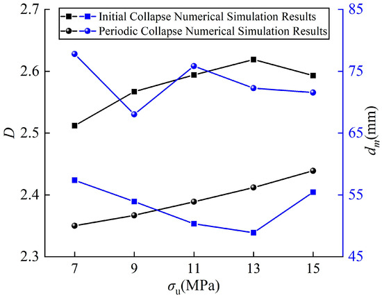
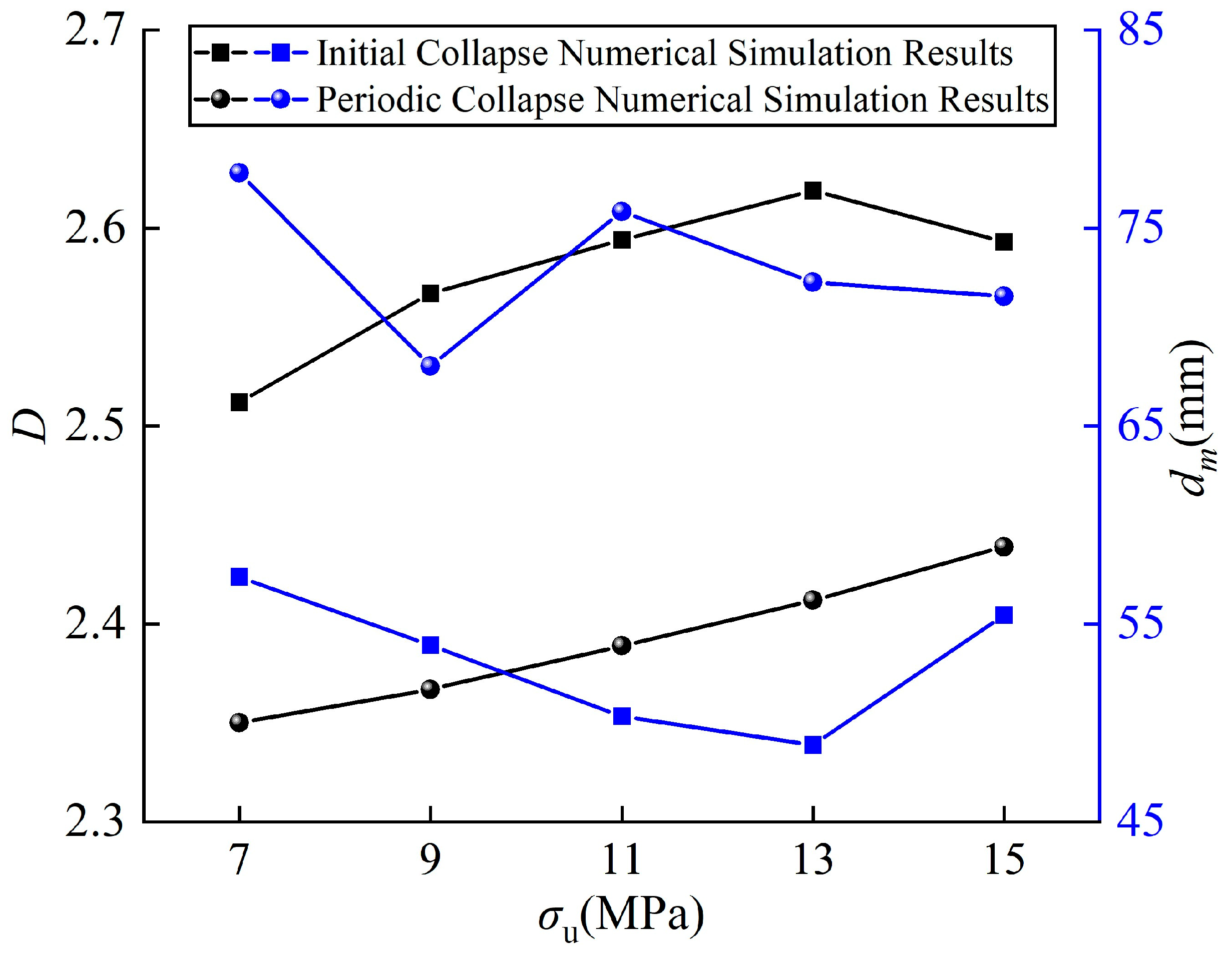
The fitting results of particle-size-mass fractal dimension and average particle size of immediate roof rock with unloading stress under initial caving and periodic caving are shown in Figure 21. The results indicate that under initial caving, the particle-size-mass fractal dimension rises continuously first and then decreases slightly with the increase in unloading stress, while the average particle size of fragments presents a trend of decreasing first and then increasing. Under periodic caving, the particle-size-mass fractal dimension increases monotonously with the rise in unloading stress, and the average particle size of fragments follows an evolutionary law of decreasing first, then increasing and slowly decreasing finally.
Figure 21.
Relationship between particle-size-mass fractal dimension, average particle size and unloading stress.
Under initial caving conditions, the immediate roof rock maintains relatively high integrity. Under the particle fabric and parameter conditions adopted in this study, local shear failure dominates at low unloading stress with insufficient crack development. As the unloading stress increases, elastic strain energy accumulates continuously and is gradually converted into the energy required for crack propagation. The sufficient development of micro-cracks leads to an increase in the particle-size–mass fractal dimension and a decrease in the particle size of fragments. When the failure mode transforms into global instability failure, energy is released instantaneously along dominant cracks and is mainly converted into macroscopic fracture energy and kinetic energy of fragments. The mesoscopic fragmentation is weakened, resulting in a decreased particle-size–mass fractal dimension and an increased particle size of fragments. For immediate roof rock under periodic caving, its bearing mechanism changes from continuous rock mass bearing to interlocking-friction bearing between fractured rock blocks. Pre-existing cracks further propagate with the increase in unloading stress, and the total energy consumed by crack propagation rises, which is manifested as a continuous increase in the particle-size–mass fractal dimension. At the low unloading-stress stage, unloading disturbance generates small-size fragments along the pre-existing fracture surfaces and thus reduces the particle size of fragments. With the growth of unloading stress, global instability failure tends to occur along macroscopic fracture surfaces in immediate roof rock, which increases the particle size of fragments. When the unloading stress reaches a relatively high level, large-size fragments are further broken, and the particle size of fragments shows a downward trend.
4.4. Analysis on Influence Mechanism of Rock Strength
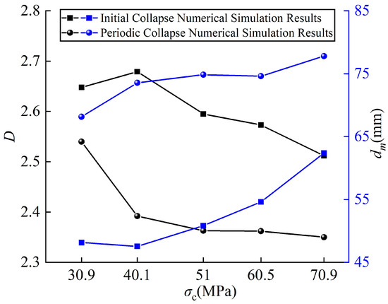
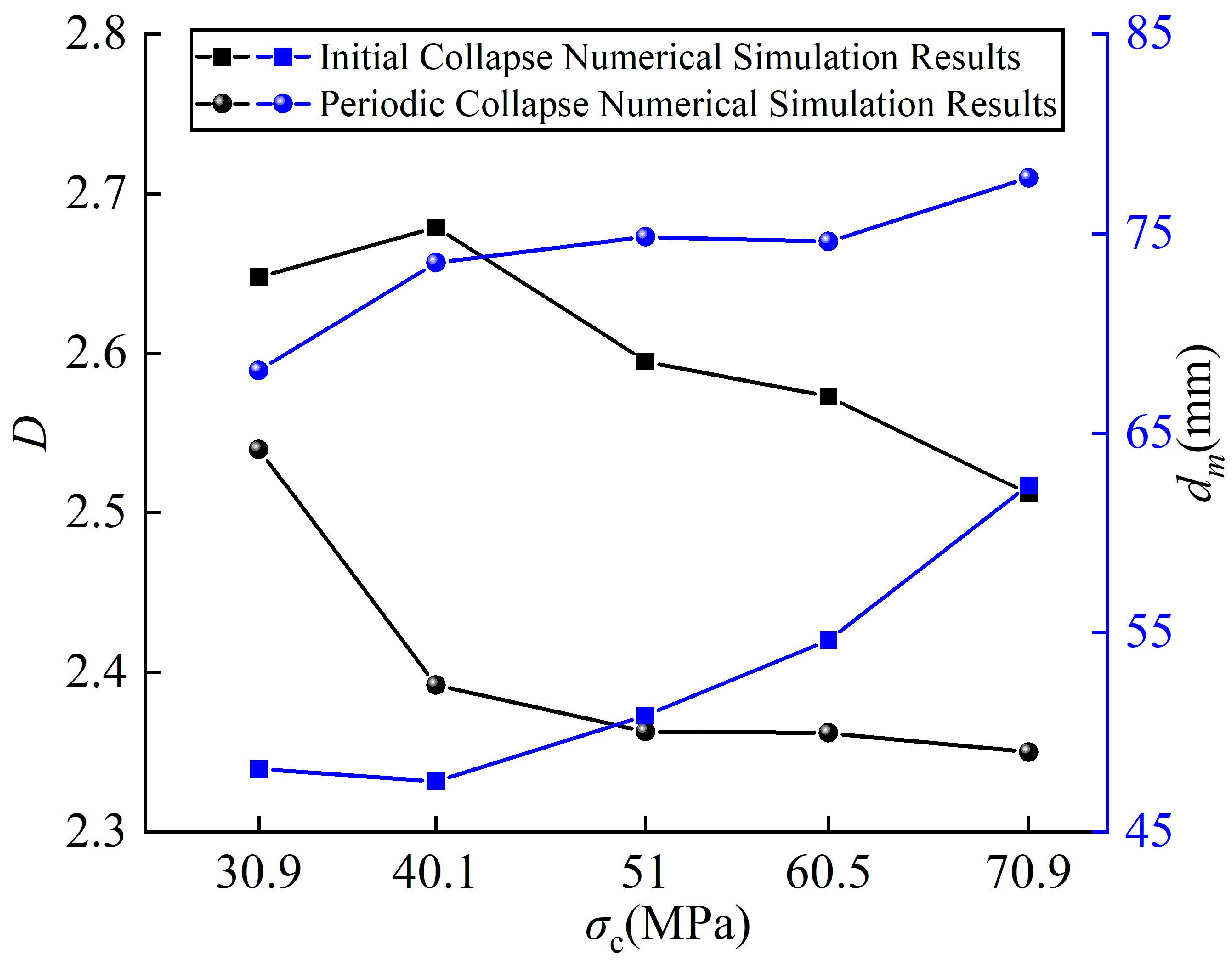
The fitting results of particle-size-mass fractal dimension and average particle size of immediate roof rock with specimen strength under initial caving and periodic caving are shown in Figure 22. The results show that under both initial caving and periodic caving conditions, the particle-size-mass fractal dimension generally decreases with the increase in specimen strength, while the average particle size of rock fragments presents an upward trend.
Figure 22.
Relationship between particle-size-mass fractal dimension, average particle size and specimen strength.
Under the particle fabric and parameter conditions adopted in this study, the input energy of low-strength specimens is gradually dissipated during the loading-unloading process, producing a large number of fine particles. As the specimen strength increases, the strain energy accumulated inside the rock mass rises continuously. Upon unloading, energy is released rapidly and concentrated on a small number of dominant cracks, and fragmentation develops along penetrating cracks. Since most of the energy is converted into the propagation of main cracks and the kinetic energy of fragments rather than the energy required for secondary crack development, the proportion of large-size fragments increases, which is manifested as a decrease in the particle-size–mass fractal dimension and an increase in the particle size of fragments.
4.5. Comparison of Main Controlling Factors During the Two Caving Stages
To highlight the differences induced by boundary conditions, specimens with identical parameters were selected for horizontal comparison, as listed in Table 5. It can be seen from the table that under the same geometric parameters, unloading stress and specimen strength, the particle-size–mass fractal dimension under periodic caving is approximately 5.8% lower, the particle size of fragments is about 28.8% higher, and the fractal dimension of crack distribution is roughly 3.8% lower than those under first caving [31,32]. The four-sided fixed support leads to relatively scattered O-X-shaped cracks at the boundaries and tensile zones for specimens under first caving. A large number of mesoscopic cracks and new fracture surfaces are generated, resulting in finer fragments and a more complex crack network. The one-free-side boundary condition for periodic caving weakens the symmetry of boundary constraints. Cracks preferentially concentrate near the left and right fixed ends and propagate toward the bottom fixed edge, eventually forming local failure governed by U-shaped cracks. Consequently, the proportion of large-size rock blocks increases.
Table 5.
Comparison on unloading fracture features of initial-caving and periodic-caving with unified parameters.
It can be concluded from Figure 19, Figure 20, Figure 21 and Figure 22 and Table 5 that the main controlling factors for the two caving stages vary with the response indicators. Owing to the four-sided symmetrical constraint under initial caving, the variation in bending stiffness caused by the thickness-width ratio exerts the most prominent effect on the particle-size-mass fractal dimension and crack fractal dimension. The average particle-size is primarily governed by specimen strength, while unloading stress determines the threshold for the transition from localized tensile-shear failure to global instability failure. The length-width ratio imposes a relatively weak influence on particle-size gradation and the global failure mode. The periodic-caving stage is dominated by the asymmetric boundary condition with three fixed sides and one free side. Stress concentration around the fixed ends governs the failure-initiation position and the local propagation path of U-shaped cracks. Among the quantitative indicators, the thickness-width ratio remains the primary influencing factor of the particle-size-mass fractal dimension. Specimen strength and unloading stress generate a more remarkable regulating effect on the crack fractal dimension and the generation of large-sized fragments. The overall influence of the length-width ratio on the particle-size-mass fractal dimension and crack morphology stays in a secondary position.
5. Conclusions
In this paper, a series of unloading fracture tests on immediate roof rock are carried out by means of numerical simulation. The variation laws with the particle-size-mass fractal dimension and unloading surface crack fractal dimension after unloading fragmentation of the immediate roof rock under initial caving and periodic caving conditions with the thickness-width ratio, length-width ratio, unloading stress and specimen strength are investigated, and the corresponding influence mechanisms are revealed. The main conclusions are summarized as follows:
- The increase in the thickness-width ratio of immediate-roof rock raises its bending stiffness and restrains bending deformation. Accordingly, the particle-size-mass fractal dimension of fragmented rock samples follows an evolution trend of first-rise-and-then-fall. The average particle-size increases at first and subsequently tends to be stable. Furthermore, crack propagation is restrained during rock fragmentation. For the unloading-surface crack fractal dimension under initial caving and periodic caving, it presents a monotonically decreasing trend and a trend of decreasing-first-and-increasing-later with the rising thickness-width ratio, respectively. Block-strip shaped fragments dominate the morphological characteristics of broken rock blocks for specimens with different thickness-width ratios.
- The particle-size-mass fractal dimension of immediate-roof rock with diverse length-width ratios after unloading-induced fragmentation stays at roughly the same level. An increase in the length-width ratio reduces the bending stiffness of specimens and restrains the development of secondary cracks, thereby raising the proportion of large-sized rock blocks and bringing about the growth of average particle-size. Under both initial caving and periodic caving conditions, the morphological hierarchy of fractured rock blocks for specimens with various length-width ratios obeys block-strip shaped > strip-slab shaped > plate-sheet shaped + flak-shaped.
- Rising unloading stress intensifies the tensile-shear failure effect. Once the unloading stress exceeds the critical value, the rock failure mode transforms into global shear failure. The particle-size-mass fractal dimension under initial caving and periodic caving both follows the tendency of increasing first and then decreasing. Meanwhile, the evolution of internal cracks inside rock specimens shifts from sustained propagation to restricted development. Hence, the crack fractal dimension on the unloading surface also rises initially and declines afterwards. Block-strip shaped fragments constitute the dominant fractured-block morphology for specimens from the two working-condition groups under all unloading-stress levels.
- The strain energy released when immediate-roof rock suffers unloading-induced failure is governed by specimen strength. Higher-strength specimens require more energy for rock failure and tend to generate large-sized fragments. Both the initial-caving and periodic-caving cases exhibit the evolutionary tendency that the particle-size-mass fractal dimension drops and the average particle-size increases. Microcracks keep propagating with the growth of specimen strength. When the specimen strength reaches a relatively high level, penetrating cracks are readily formed upon failure and the propagation of secondary cracks is restrained. For this reason, the crack fractal dimension increases firstly and then decreases as specimen strength rises. Block-strip shaped fragments remain the dominant fractured-block morphology for specimens with diverse strength under the two working-condition groups.
- Under uniform-parameter conditions, the particle-size-mass fractal dimension and crack fractal dimension for periodic caving are approximately 5.8% and 3.8% lower than those of initial caving separately, and the average particle-size increases by roughly 28.8%. Initial caving produces tension-bending and tensile-shear coupled failure characterized by O-X-shaped cracks. In the case of periodic caving, cracks preferentially initiate near the left-hand and right-hand fixed ends and then propagate toward the bottom fixed edge, which eventually creates localized failure governed by U-shaped cracks.
This numerical simulation assumes that the rock mass is homogeneous and isotropic. Primary joints are not taken into account and the boundary conditions have been simplified. The numerical model suffers from the size-scale effect. Besides, supporting evidence from laboratory tests and in situ measurement data is absent. Furthermore, the manually outlined crack morphology is subject to subjective human influence. In addition, to ensure the comparability among different parameter-controlled working conditions, a fixed random seed and identical porosity were adopted to generate the particle models. Therefore, the conclusions of this study are limited to the particle fabric and parameter-calibration conditions used in this paper.
Author Contributions
Conceptualization, Y.Q. and N.X.; methodology, Y.Q. and N.X.; validation, Y.Q. and Z.Z.; formal analysis, Y.Q., N.X. and J.Q.; resources, Y.Q. and N.X.; writing—original draft preparation, Y.Q., Z.Z. and L.C.; writing—review and editing, Y.Q., Z.Z. and J.Q.; supervision, Y.Q., N.X. and J.Q.; funding acquisition, Y.Q. and N.X. All authors have read and agreed to the published version of the manuscript.
Funding
This research was funded by the National Natural Science Foundation of China, grant no. 42230709 and no. 42302315 and Young Elite Scientists Sponsorship Program of the Beijing High Innovation Plan, grant no. 20251081.
Data Availability Statement
The data used in this study are available from the corresponding author upon reasonable request.
Acknowledgments
We sincerely thank the editors and all reviewers for their constructive and excellent reviews that helped improve the manuscript.
Conflicts of Interest
The authors declare no conflicts of interest.
Abbreviations
The following symbols are used in this paper:
| a | Side length of the square grid |
| D | Particle-size–mass fractal dimension |
| d | Particle size of fragments |
| D′ | Fractal dimension of crack distribution |
| dM | Maximum particle size of fragments |
| dm | Mean fragment size of each mass distribution interval |
| dmin | Minimum particle size of fragments |
| l/w | Length-width ratio |
| Md | Cumulative mass of fragments with particle size smaller than d |
| Mt | Total mass of the fragmented specimen |
| N | Number of grids covering cracks |
| t/w | Thickness-width ratio |
| σc | Specimen strength |
| σu | Unloading stress |
References
- Song, Z.; Konietzky, H.; Wu, Y.; Du, K.; Cai, X. Mechanical behaviour of medium-grained sandstones exposed to differential cyclic loading with distinct loading and unloading rates. J. Rock Mech. Geotech. Eng. 2022, 14, 1849–1871. [Google Scholar] [CrossRef] [Scilit]
- Lai, J.; Liu, Y.; Cong, Y.; Liu, Y. Study on the macro and micro characteristics of the influence of deviator stress on true triaxial unloading failure. Sci. Rep. 2025, 15, 19271. [Google Scholar] [CrossRef] [Scilit] [PubMed]
- Chang, X.; Zhang, X.; Yu, J.; Tan, W.; Li, W. Failure characteristic of fissured rock specimens under true triaxial unloading conditions. Theor. Appl. Fract. Mech. 2024, 131, 104387. [Google Scholar] [CrossRef] [Scilit]
- Akdag, S.; Karakus, M.; Taheri, A.; Nguyen, G.; Manchao, H. Effects of Thermal Damage on Strain Burst Mechanism for Brittle Rocks Under True-Triaxial Loading Conditions. Rock Mech. Rock Eng. 2018, 51, 1657–1682. [Google Scholar] [CrossRef] [Scilit]
- Peng, Y.; Dongdong, P.; Ju, L.; Zhiguo, H.; Wensong, X.; Zhongsi, D. Experiment on deformation and failure characteristics of sandstone at different unloading rates. Alex. Eng. J. 2023, 75, 209–219. [Google Scholar] [CrossRef] [Scilit]
- Hu, X.; Cai, J. Research on the First Breaking Mechanism of the Main Roof of Coal Seam with High Dip Angle. Adv. Civ. Eng. 2020, 2020, 8820625. [Google Scholar] [CrossRef] [Scilit]
- Wang, Y.; Du, F.; Zhang, J.; Pei, Y.; Wang, J.; Yang, J.; Chen, H.; Chen, J.; He, M. Mechanism-informed overburden control based on granular load-bearing body: Application in shallow-buried coal seams. Tunn. Undergr. Space Technol. 2026, 170, 107382. [Google Scholar] [CrossRef] [Scilit]
- Faradonbeh, R.S.; Taheri, A.; e Sousa, L.R.; Karakus, M. Rockburst assessment in deep geotechnical conditions using true-triaxial tests and data-driven approaches. Int. J. Rock Mech. Min. Sci. 2020, 128, 104279. [Google Scholar] [CrossRef] [Scilit]
- Pan, C.; Liu, C.; Zhao, G.; Yuan, W.; Wang, X.; Meng, X. Fractal Characteristics and Energy Evolution Analysis of Rocks under True Triaxial Unloading Conditions. Fractal Fract. 2024, 8, 387. [Google Scholar] [CrossRef] [Scilit]
- Dong, C.; Fan, C.; Lu, X.; Zhao, G.; Qi, M.; Qin, R. Mechanical and Energy Evolution Characteristics of Sandstone under True Triaxial Cyclic Loading. Appl. Sci. 2023, 13, 7230. [Google Scholar] [CrossRef] [Scilit]
- Li, W.; Wang, Z.; Feng, G.; Zhang, H.; Du, J.; Li, H.; Duan, M. Dilation and energy evolution mechanisms of sandstone under true-triaxial mining unloading conditions. Geomech. Geophys. Geo-Energy Geo-Resour. 2024, 10, 58. [Google Scholar] [CrossRef] [Scilit]
- Liu, C.; Zhao, G.; Pan, C.; Meng, X.; Xu, W. Experimental Study of Rock Failure and Fractal Characteristics Under True Triaxial Unloading. Fractal Fract. 2025, 9, 182. [Google Scholar] [CrossRef] [Scilit]
- Liu, J.; Li, Q.; Lu, S.; Wang, Z.; Wang, H. Study on failure mechanical behavior of coal in triaxial stress loading and unloading path. Bull. Eng. Geol. Environ. 2023, 82, 417. [Google Scholar] [CrossRef] [Scilit]
- Li, J.; Lin, F.; Liu, H.; Zhang, Z. Triaxial Experimental Study on Changes in the Mechanical Properties of Rocks Under Different Rates of Confining Pressures Unloading. Soil Mech. Found. Eng. 2019, 56, 246–252. [Google Scholar] [CrossRef] [Scilit]
- Chen, Y.; Zuo, J.; Li, Z.; Dou, R. Experimental investigation on the crack propagation behaviors of sandstone under different loading and unloading conditions. Int. J. Rock Mech. Min. Sci. 2020, 130, 104310. [Google Scholar] [CrossRef] [Scilit]
- Guo, J.; Liu, P.; Fan, J.; Shi, X.; Huang, X. Influence of Confining Pressure Unloading Rate on the Strength Characteristics and Fracture Process of Granite Using Lab Tests. Adv. Mater. Sci. Eng. 2021, 2021, 7925608. [Google Scholar] [CrossRef] [Scilit]
- Du, K.; Tao, M.; Li, X.B.; Zhou, J. Experimental Study of Slabbing and Rockburst Induced by True-Triaxial Unloading and Local Dynamic Disturbance. Rock Mech. Rock Eng. 2016, 49, 3437–3453. [Google Scholar] [CrossRef] [Scilit]
- Zhang, C.; Fu, J.; Wang, Y. Numerical simulation of true triaxial unilateral unloading effect of fractured rock. Eng. Comput. 2023, 40, 2110–2128. [Google Scholar] [CrossRef] [Scilit]
- Wang, Y.; Chen, F.; Li, Y.; Sun, X.; Liu, N. Effect of Confining Pressure Unloading Rate on Mechanical and Energy Characteristics of Coal-Rock Combinations. Geotech. Geol. Eng. 2023, 42, 2259–2270. [Google Scholar] [CrossRef] [Scilit]
- Liu, C.; Zhao, G.; Xu, W.; Meng, X.; Liu, Z.; Cheng, X.; Lin, G. Experimental study on failure characteristics of single-sided unloading rock under different intermediate principal stress conditions. Int. J. Min. Sci. Technol. 2023, 33, 275–287. [Google Scholar] [CrossRef] [Scilit]
- Chen, P.; Cui, J.; Zhou, X. Numerical Simulations on Effects of Unloading on Occurrence of Rock Lateral Cracks. Appl. Mech. Mater. 2014, 2916, 635–638. [Google Scholar] [CrossRef] [Scilit]
- Yang, Y.; Zhang, Z. Dynamic fracturing process of fissured rock under abrupt unloading condition: A numerical study. Eng. Fract. Mech. 2020, 231, 107025. [Google Scholar] [CrossRef] [Scilit]
- Chen, Y.; Deng, Z.; Huang, L.; Gui, Y.; Lin, H.; Wang, Y.; Sun, W. A novel cyclic loading–unloading contact model for rock using discrete element method. Omputational Part. Mech. 2025, 12, 2455–2474. [Google Scholar] [CrossRef] [Scilit]
- Deng, Y.; Chen, M.; Jin, Y.; Zou, D. Theoretical analysis and experimental research on the energy dissipation of rock crushing based on fractal theory. J. Nat. Gas Sci. Eng. 2016, 33, 231–239. [Google Scholar] [CrossRef] [Scilit]
- Cai, G.; Xiong, Y.; Lin, L. Experimental Study on the Fractal Characteristics of Rocks Crushing. MATEC Web Conf. 2015, 25, 02008. [Google Scholar] [CrossRef] [Scilit]
- Tang, S.; Liu, X.; Chen, K. Study on the Ejective Debris of Granite Biaxial Rockburst Test. In Proceedings of the 2017 5th International Conference on Machinery, Materials and Computing Technology(ICMMCT 2017); Hou, H., Han, Z., Eds.; Atlantis Press: Amsterdam, The Netherlands, 2017; pp. 200–205. [Google Scholar]
- Xie, H.; Chen, Z. Fractal geometry and fracture of rock. Acta Mech. Sin. 1988, 4, 255–264. [Google Scholar] [CrossRef] [Scilit]
- Basirat, R.; Goshtasbi, K.; Ahmadi, M. Determination of the Fractal Dimension of the Fracture Network System Using Image Processing Technique. Fractal Fract. 2019, 3, 17. [Google Scholar] [CrossRef] [Scilit]
- Huang, J.; Wei, X.; Zheng, Z.; Su, X.; Zuo, J. Linear fractal evolution characteristics of rock crack distributions during loading process. Sci. Rep. 2024, 14, 18303. [Google Scholar] [CrossRef] [Scilit] [PubMed]
- Chen, H.; Ye, Y.C.; Wang, Q.H.; Hu, N.Y.; Liu, R.; Jiang, H.M. Study of direct roof failure form of soft layer in roadway based on rock beam-block theory. Rock Soil Mech. 2020, 41, 1447–1454. [Google Scholar] [CrossRef]
- Zhang, Q.; Meng, X.; Zhao, G. Energy Evolution and Fractal Characteristics of Sandstones Under True Triaxial Cyclic Loading and Unloading. Fractal Fract. 2024, 8, 714. [Google Scholar] [CrossRef] [Scilit]
- Hou, T.; Xu, Q.; Zhou, J. Size distribution, morphology and fractal characteristics of brittle rock fragmentations by the impact loading effect. Acta Mech. 2015, 226, 3623–3637. [Google Scholar] [CrossRef] [Scilit]

Disclaimer/Publisher’s Note: The statements, opinions and data contained in all publications are solely those of the individual author(s) and contributor(s) and not of MDPI and/or the editor(s). MDPI and/or the editor(s) disclaim responsibility for any injury to people or property resulting from any ideas, methods, instructions or products referred to in the content. |
© 2026 by the authors. Licensee MDPI, Basel, Switzerland. This article is an open access article distributed under the terms and conditions of the Creative Commons Attribution (CC BY) license.