


Abstract
This paper investigates the effectiveness of integrating a matrix converter (MC) into a wind turbine system based on a Doubly Fed Induction Generator (DFIG), focusing on the indirect control of active and reactive power using fractional regulators. To evaluate the performance of this architecture, three distinct configurations are studied and compared: (i) a conventional system using an AC-DC-AC converter combined with a conventional PI regulator, (ii) a structure integrating a matrix converter with a PI regulator, and (iii) an advanced combination of MC with a fractional regulator. Simulation results demonstrate that this latter solution offers significant improvements in dynamic performance, more precise regulation of active and reactive power, and higher energy efficiency than the other two methods.
1. Introduction
In recent years, wind energy conversion systems (WECS) based on Doubly Fed Induction Generators (DFIGs) have attracted considerable interest due to their ability to operate over a wide range of speeds and independently manage active and reactive power. The classic DFIG configuration uses a series converter topology with a DC coupling capacitor to control rotor and grid currents. Despite its widespread use, this structure has disadvantages, including significant switching losses, limited performance, and reduced reliability under wind fluctuations or grid outages [1,2,3,4].
Traditional proportional-integrator (PI) controllers and vector control methods remain dominant in DFIG management, thanks to their simplicity and well-established tuning procedures [5,6,7]. However, they generally do not provide optimal efficiency in the presence of variable parameters, grid failures, or random wind conditions [8,9]. To address these difficulties, several advanced control methods have been proposed, including sliding-mode, adaptive, backstepping, and super-twisting algorithms. These provide enhanced resilience but involve greater design complexity [10,11].
The recent adoption of fractional-order (FO) control methods has generated considerable research interest. By extending the principles of differentiation and integration to fractional orders, FOPI and FOPID controllers offer greater flexibility in tuning dynamic behaviour. This manifests as greater robustness, faster transient response, and improved disturbance rejection [12,13,14]. Research has shown that fractional-order-based approaches can outperform traditional controllers in Doubly Fed Induction Generators (DFIGs), especially under nonlinear or unstable operating conditions [13,14].
Despite these advances, the combined use of matrix converters and fractional-order controllers in DFIG-based wind energy conversion systems (WECS) remains largely unexplored. Combining these two emerging technologies could significantly optimise conversion rates, power quality, and dynamic stability. The objective of this study is to examine this combination and propose an improved control framework that leverages the advantages of both methods to achieve superior system performance under realistic wind and grid conditions.
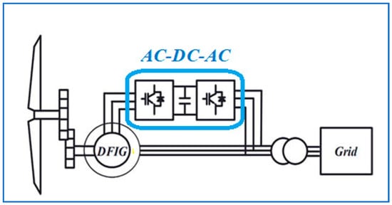
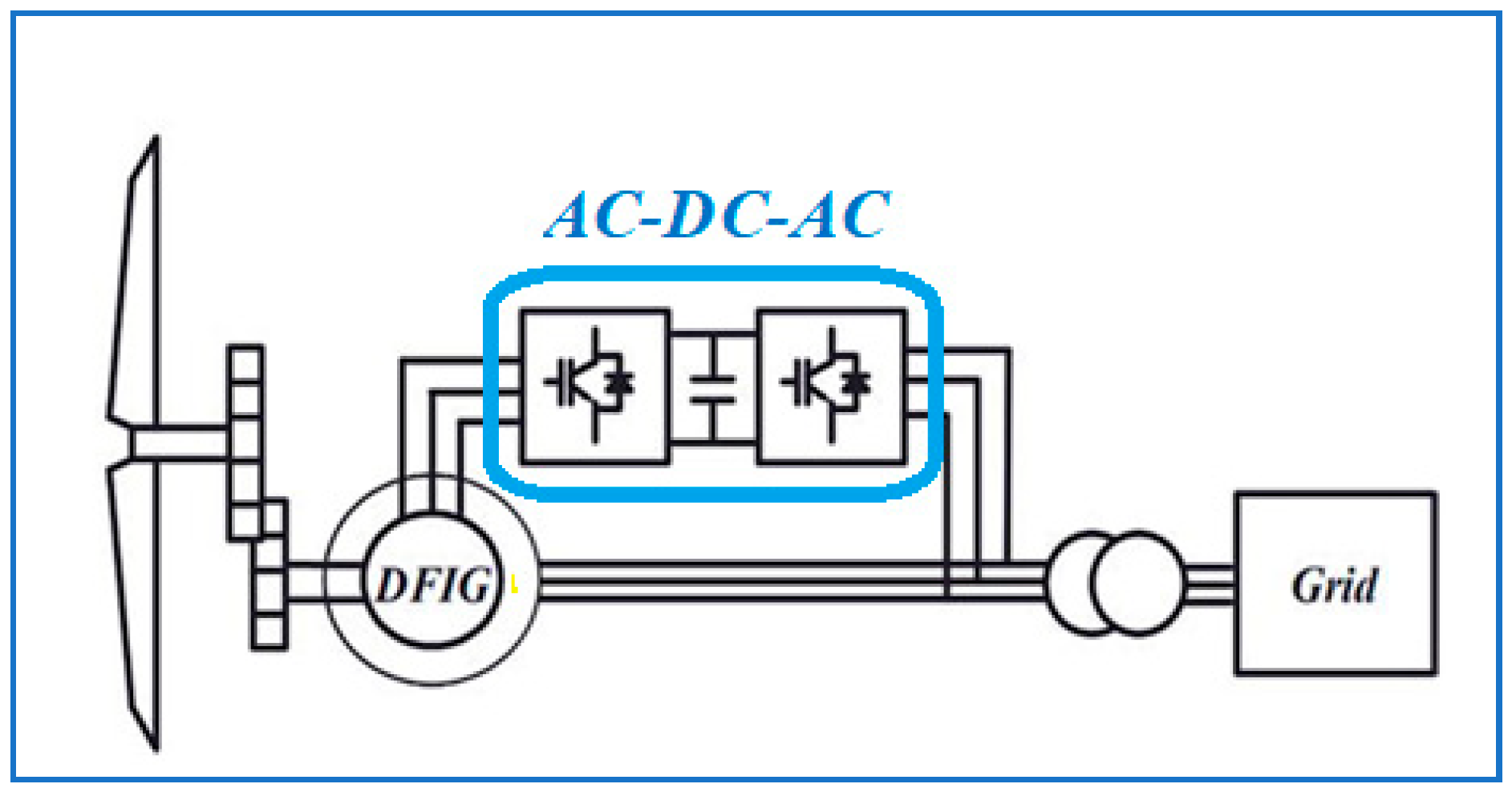
Figure 1 illustrates the schematic of a conventional WPC based on a DFIG. The turbine, driven by the wind, transmits its mechanical energy to the generator via a speed gearbox. The stator is directly connected to the electrical grid, and the rotor is interfaced via three-phase static power converters, thus ensuring optimal control of power flows and the stability of the entire system. Traditionally, this machine is combined with an AC-DC-AC converter that manages energy flow between the wind turbine and the electricity grid. However, this solution has limitations, particularly related to the complexity of the two-stage conversion, additional losses, and the volume of intermediate components.
Figure 1.
Architecture of a DFIG-based wind system with rotor-side AC/DC/AC converter.
To overcome these constraints, the use of the matrix converter (MC) has been proposed as an interesting alternative. The latter enables direct AC-AC conversion without a DC link, improving the system’s compactness, reliability, and overall efficiency while allowing bidirectional power exchange.
In wind energy systems, integrating a direct current (DC) link between the two-stage AC/DC/AC converters significantly increases the overall weight and physical dimensions of the conversion system [15]. This DC bus plays a critical role in ensuring continuous power flow and facilitating the connection between the wind energy conversion chain and the electrical grid. However, such architecture presents several notable drawbacks, including increased power losses, reduced reliability, greater structural complexity, higher costs, and a detrimental impact on the wind system’s overall lifespan [16]. Conversely, adopting a multilevel matrix converter (MC) offers a promising alternative, enabling optimisation of key performance factors such as system compactness (in terms of both weight and volume), energy and thermal efficiency, architectural simplicity, and mitigation of electromagnetic interference.
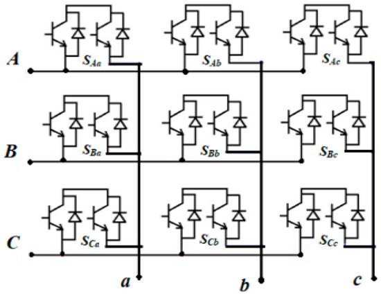
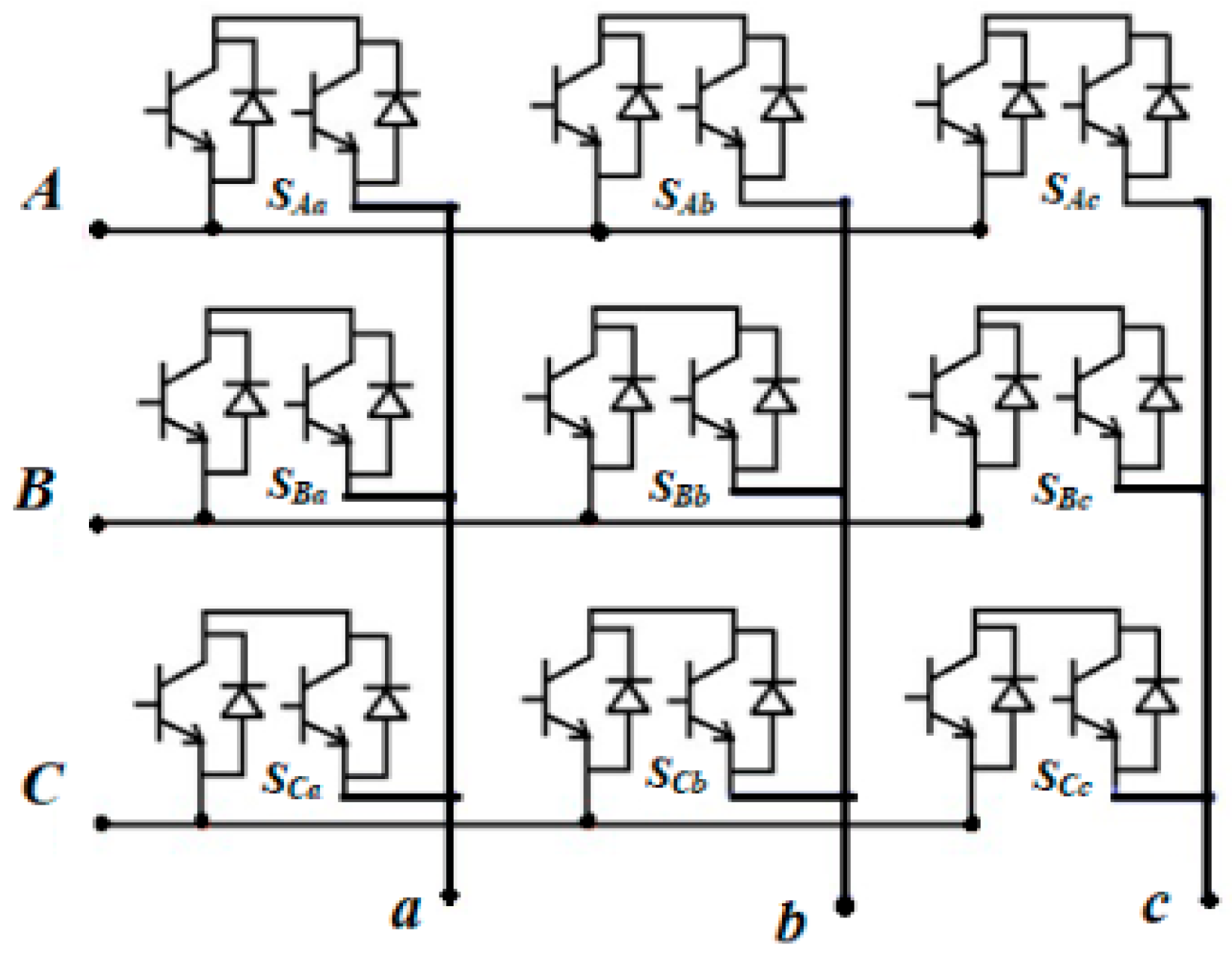
The matrix converter (MC) is an advanced power-conversion architecture that enables direct AC-to-AC conversion, using nine bidirectional switches instead of the twelve typically required in conventional two-level AC/DC/AC converters. This topology is based on a matrix of bidirectional current and voltage-switches that connect the input and output phases, enabling bidirectional power flow between the grid and the load while precisely controlling the output voltage and frequency.
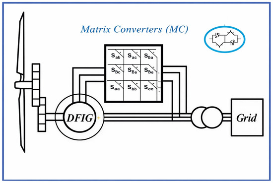
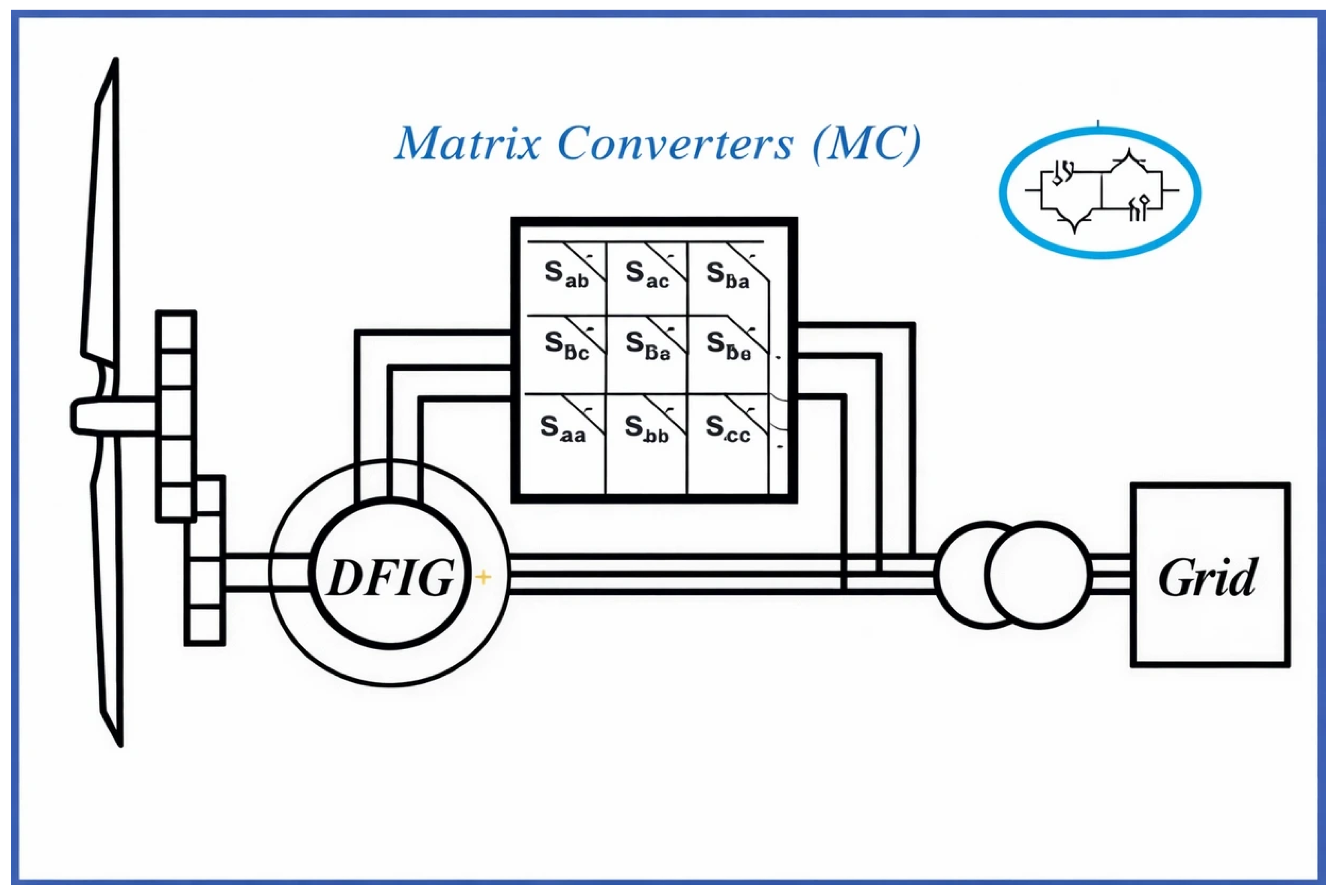
Figure 2 depicts the system under consideration, in which the generator stator is directly connected to the grid, while the rotor is interfaced via a matrix converter (AC-AC). This converter facilitates the synchronisation of rotor power with the grid at constant voltage and frequency, and enables independent control of active and reactive power flows between the generator stator and the grid.
Figure 2.
Architecture of a DFIG-based wind system with MC.
Given the nonlinear behaviour of the wind energy system and its susceptibility to parameter variations and external disturbances, adopting a robust control strategy is essential. In this regard, fractional-order controllers exhibit superior robustness and adaptability compared to conventional PI regulators, offering improved response tracking and reduced sensitivity to nonlinearities and uncertainties.
Accordingly, this study implements a control strategy to manage the injection of active and reactive power into the grid via a three-phase matrix converter connected to the rotor. The control algorithm is based on minimising total harmonic distortion (THD). Furthermore, the stator-side control is ensured using a fractional-order PIα controller, which enables effective decoupling of active and reactive powers.
The motivation for this work arises from the growing penetration of wind energy systems into modern power grids and the increasing performance requirements imposed on grid-connected converters. Doubly Fed Induction Generators (DFIGs) remain one of the most widely adopted technologies in variable-speed wind turbines due to their flexibility and efficiency; however, conventional AC–DC–AC converter structures combined with classical PI controllers often face limitations in terms of harmonic distortion, dynamic response, power oscillations, and overall power quality. In addition, the demand for more compact, reliable, and energy-efficient conversion systems has encouraged the exploration of alternative topologies such as matrix converters. In this context, the present study aims to enhance the decoupled control of active and reactive power while improving dynamic performance and reducing total harmonic distortion. By integrating a matrix converter with fractional-order controllers, this work aims to address the shortcomings of traditional approaches and contribute to the development of high-performance, next-generation DFIG-based wind energy conversion systems.
The remainder of this paper is arranged as follows: Section 2 is devoted to the mathematical modelling of the main components of the wind turbine. The power control strategy applied to the DFIG is presented in Section 3. Section 4 introduces the structure and control algorithm of the matrix converter (MC) used to power the DFIG. Section 5 reports the simulation results generated in the MATLAB/Simulink (https://www.mathworks.com/products/matlab.html, accessed on 11 January 2026) framework for a DFIG governed by an MC in conjunction with fractional PIα controllers. These results are compared with those from the same system powered by an MC with conventional PI regulators, as well as with those obtained with a two-level AC/DC/AC inverter also using conventional PI regulators. Finally, Section 6 presents the conclusions and perspectives.
2. Mathematical Modelling of Wind Turbine Components
This section presents the mathematical models used to describe the dynamic behaviour of the wind turbine system and its main components. Accurate modelling is essential for analysing performance, designing control strategies, and evaluating system stability under varying wind and operating conditions. The section first introduces the overall mathematical representation of the wind turbine, including aerodynamic and mechanical dynamics. It then details the mathematical modelling of the Doubly Fed Induction Generator (DFIG), which plays a central role in variable-speed wind energy conversion systems.
2.1. Mathematical Modelling of Wind Turbine
During turbine conversion of wind kinetic energy, the aerodynamic torque applied to the DFIG rotor converts mechanical power into electrical power. [16,17]. We assume that the sum of all mechanical properties defines the mechanical system; the outcome is a mechanical model with two masses. When the wind acts on the blades of a wind turbine, the blades rotate and generate mechanical power Pt, which is transmitted to the turbine shaft and can be expressed as
where β is the blade pitch angle (degrees), is the air density (Kg/m3), r is the rotor radius, Vv is the wind speed (m/s), and λ is the tip-speed ratio, there is a crucial dimensionless parameter that compares the speed of the blade tips to the wind speed:
Ωt: is the rotational angular speed of the rotor (rad/s) of the wind turbine;
Cp: Coefficient of performance that describes aerodynamic efficiency, based on wind turbine characteristics. Its expression is as follows [18]:
The expression of the mechanical torque on the turbine shaft is
The turbine’s rotating shaft supports three movable blades. To provide the necessary wind energy to the DFIG, a multiplier controls the mechanical wind speed, , which is generated by the aerodynamic shape of the blades [19].
Jt: Turbine moment of inertia of the 3 blades (Kg · m2);
Jm: Inertia Moment of the DFIG (Kg · m2);
f: The coefficient of viscous friction of DFIG;
Tem: The electromagnetic DFIG torque and is the gear ratio;
Tt: The aerodynamic torque applied to the low-speed shaft;
Tg: The torque transmitted to the high-speed shaft of the gearbox.
Equations (6) and (7) reflect the torque and speed conversion between the low-speed shaft (turbine side) and the high-speed shaft (generator side), where (G) is the gearbox ratio.
The dynamics of the mechanical system on the DFIG shaft are
2.2. Mathematical Modelling of the DFIG Model
The DFIG is one of the most reliable generators used in wind farms, especially when wind speeds (WS) vary. This generator offers several advantages over other generators. Most notable are its simplicity of control, low cost, minimal maintenance, and high durability [20,21]. The Park transform can be used to model the DFIG. The modulation of the DFIG is based on the following assumptions: the air-gap thickness and its uniformity; the slots are negligible; magnetic-circuit saturation is negligible; the winding resistances are constant; and the magneto-motive force is sinusoidal. According to the work [21], the stator and rotor voltage equations for DFIG are listed in Equation (10).
In this notation, vsd, vsq, vrd, and vrq denote the stator and rotor voltages in the d–q frame, while isd, isq, ird, and irq represent the corresponding currents. Rs and Rr are the stator and rotor resistances, and and r are respectively the electrical stator and rotor angular speed (rad/s). The electromagnetic torque Tem is given by the following Equation (11), where p is the number of pole pairs, and LM is the mutual inductance.
To achieve this goal, equations are derived that relate the stator active and reactive powers to the rotor quantities used to control the machine. This process consists of orienting the d-axis of the rotating reference frame along the stator flux vector, thereby ensuring decoupling between stator and rotor quantities [2]. That is,
Using Equation (12), the generator torque can be expressed by Equation (13).
Taking into account (12), the flux Equations become
It is assumed that the electrical network is stable and that the individual voltage vs. and stator flux ϕs are constant. Equation (10) for the machine can be written as Equation (15).
where ωs is the electrical pulsation of the stator quantities, from which we deduce that
Therefore, Equation (17) can be derived from Equation (14).
It is known that Ps and Qs are written as
Considering Equation (18), the expressions for the powers reduce to
So, by substituting the currents into the previous equation with their expressions (17), Equation (20) can be written.
From Equation (16), Equation (21) can be written.
The expression for the powers in Equation (20) can be rewritten in the form below:
These expressions show that these stator power components can be controlled independently.
with
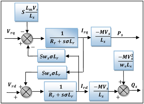
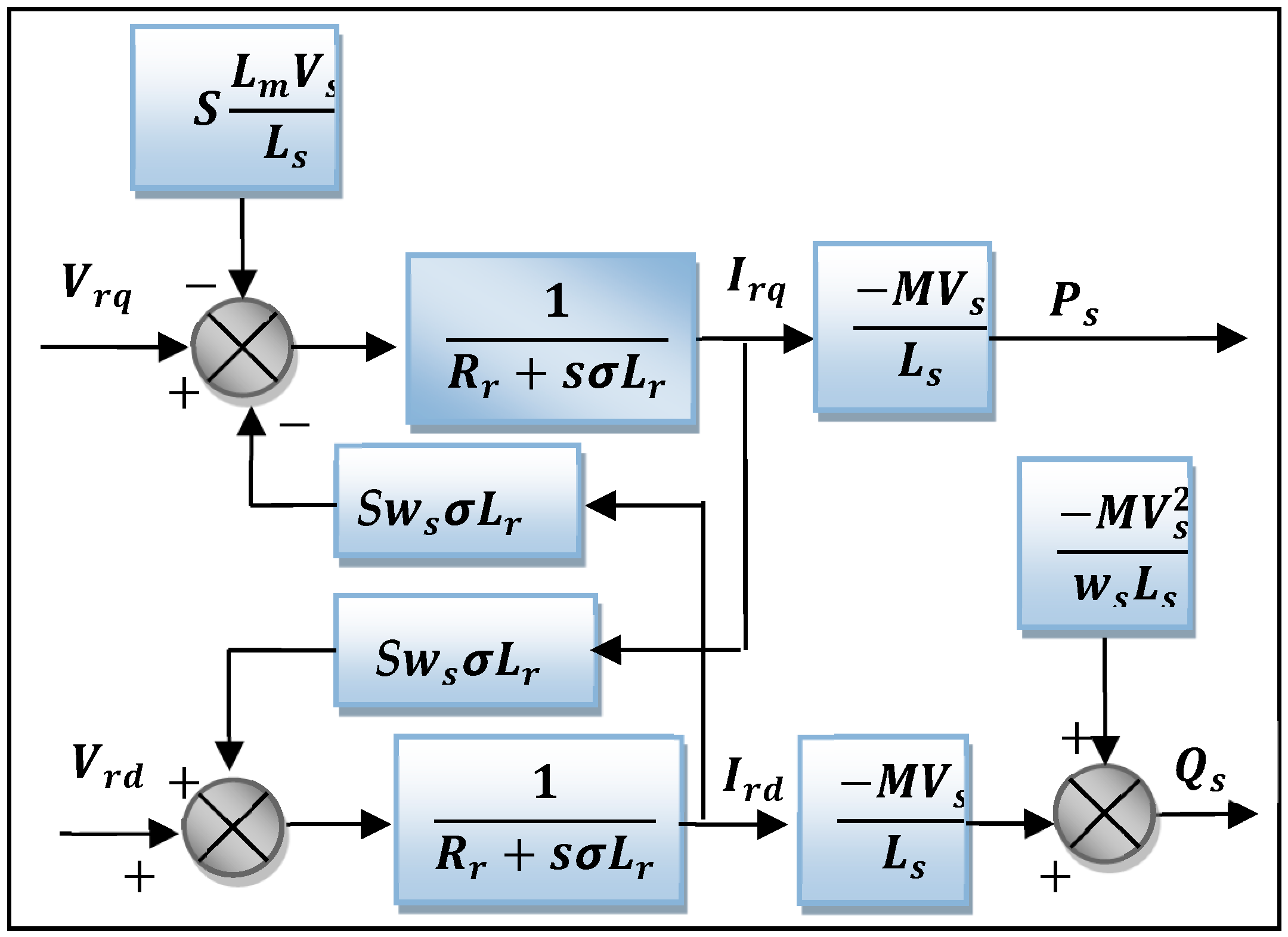
where S is the slip ratio, defined as = (ωs − ωr)/ωs, and corresponds to the slip angular frequency. Based on the previous equations, a model of the generator can be drawn. Figure 3 shows the mathematical model of the DFIG used in this work, where s = d/dt and S is the slip, illustrating the relationship between the voltage applied to the machine’s rotor and the stator powers. To implement the DFIG model in this paper, MATLAB is used.
Figure 3.
Block diagram of the DFIG model.
3. Power Control Strategy Applied to the DFIG
3.1. Indirect Power Control with Classical PI Regulators
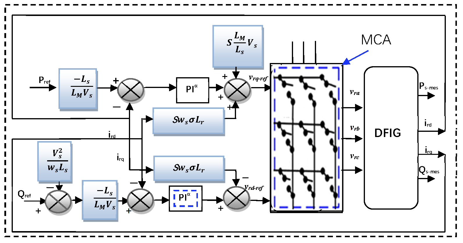
It can be observed that the powers and voltages are related through a first-order transfer function. Moreover, given the low slip values, vector control can be implemented without difficulty, since coupling effects remain weak and the d- and q-axes can be regulated independently. The rotor currents irq and ird correspond respectively to the stator active power Ps and the stator reactive power Qs and must therefore track their reference values. Figure 4 shows the block diagram of the indirect control without the power loop used in this study. [22]. The figure shows the vector control scheme of a doubly fed asynchronous generator (DFIG), commonly used in wind power generation systems. This control system allows independent control of the active power (P) and reactive power (Q) injected into the electrical network from the rotor currents irq and ird, respectively. From the Pref and Qref set points, the reference currents are calculated using relationships dependent on the machine parameters. Figure 4 shows a Block diagram of indirect control without a power loop.
Figure 4.
Block diagram of indirect control without a power loop.
These reference currents are compared with the measured currents to generate an error signal, which PI regulators then process. The regulator outputs generate the reference voltages vrq-ref and vrd-re, which are necessary to control the static converter connected to the rotor. Compensation terms for the dynamic couplings between the d- and q-axes are added to linearise the system. Finally, these reference voltages are applied to the rotor via a converter, allowing dynamic regulation of the active and reactive powers exchanged with the network. This type of control ensures better dynamic performance, flexibility in energy management, and efficient integration into modern electrical systems.
Classic PI controllers are designed to compensate for the process time constant [23]. The transfer functions related to the open-loop mapping control system are as follows:
By applying the pole compensation method to the transfer function, Equation (26) can be written.
The system has a set response time of about 12 ms. The machine characteristics and response time are used in this case to express the PI controller gains as follows, with the control system
3.2. Indirect Power Control with Classical PI Fractional
Despite the many advantages of the conventional PID controller, its widespread use is limited by notable disadvantages, including its high sensitivity to variations in machine parameters. This sensitivity often leads to increased current ripples and higher total harmonic distortion (THD). Several methods have been proposed to address this issue, most of which rely on intelligent algorithms to tune the PID gains adaptively [24]. Its performance is significantly affected by changes in machine parameters, which constitute its most critical limitation.
To address these challenges, this paper proposes using a fractional-order PID controller in combination with an MC-type converter to enhance DFIG performance. The fractional-order control strategy is chosen for its excellent dynamic response, high robustness, ease of implementation, and minimal dependence on the system’s mathematical model [25]. This makes it a highly suitable and efficient solution for advanced control of DFIG-based systems. Fractional calculus is an extension of classical differential and integral calculus, where derivatives and integrals can be of fractional order, that is, non-integer.
A fractional controller uses these fractional derivatives/integrals to control a system. The most common is the PIαDλ controller.
where α and λ are the fractional-order control gain and Kp, Ki, and Kd are the values of the proposed controller gains, where the dynamic response can be adjusted and modified.
From Equation (30), it is noted that the PID controller based on fractional-order control is simple, inexpensive, and has few gains, making it easy to adjust. Also, this controller does not require precise knowledge of the machine’s mathematical model, which gives better results when the machine’s parameters change. According to the work done in [24,25,26], the fundamental fractional-order operator is defined in Equation (31).
where n and t are the limits, α is the operation’s order. The definitions for integral and derivative of fractional order that are largely used are Riemann–Liouville (R-L) [27]. The initial definition is as follows.
The fractional order derivative is expressed by
where Γ(x) is the Euler’s Gamma function; t0 and t are the operation bounds; α is the number identifying the fractional order and 0 < α < 1; and h is the sampling period. For the derivative and the fractional integral of the definitions of Riemann–Liouville (R-L), the Laplace transform is used [28].
Fractional-order models can be implemented using the “Singularity function method” presented by Charef et al. [29,30,31] for its simple implementation. The following continuous transfer function defines a fractional-order control system.
where G(z) is the discrete transfer function, it can be found as follows:
where w(z−1) is the discrete equivalent of the Laplace operator s. Consequently, the subsequent approximation [29,30] is
where ωc is the frequency calculated on the interval ω ∈ [ωl, ωh].
At this stage, it is paramount to calculate the coefficients for the purpose of obtaining the maximum deviation of (dB) from the initial amplitude response in the frequency domain.
The poles and zeros of the approximate rational function have been obtained by applying the equations below:
This expression formulates the error criterion:
For the control system, α is set to 0.67, where the frequency band [wb, wh] = [0.1 rad/sec, 10 rad/sec], with y = 1 dB, ε = 10 − 5, and α = 0.67.
The fractional order was selected as 0.67 based on a combination of theoretical feasibility and empirical tuning. A series of preliminary simulations was conducted within the controller’s stable operating range, and different fractional orders were evaluated for overshoot, settling time, steady-state error, and robustness. The results indicated that an order of 0.67 achieved the best overall performance compromise. Moreover, this value falls within the commonly used range reported in fractional-order control studies, further validating its rationality. The approximation by the Charef method of is given by the following equation:
4. Modelling the Matrix Converter
In the two-stage topology, the input AC voltage is first rectified to DC by a rectifier stage, then stored temporarily in a DC-link capacitor, and finally inverted back to AC by a voltage-source inverter. This structure provides natural energy buffering and simplified modulation but requires bulky DC-link capacitors, which increase system size and reduce lifetime due to capacitor ageing.
In contrast, the matrix converter performs direct AC–AC conversion without an intermediate DC-link energy storage element. It uses an array of bidirectional switches to connect input phases to output phases via direct controlled modulation. This eliminates the DC-link capacitor, resulting in a more compact structure, improved power density, and potentially longer system lifetime. However, it introduces more complex commutation strategies and stricter control requirements to prevent short-circuit or open-circuit conditions.
The MC is a brand-new topology for direct frequency converters. It allows the development of a system of fixed electrical network parameters, with variable voltages in terms of amplitude and frequency [32]. This is accomplished by connecting each input phase to each output phase using a matrix of bidirectional voltage- and current-switching elements. We note that no intermediate circuit is used as a direct frequency converter (DC continuous bus). It therefore offers many advantages over similar devices, including its compact size, lightweight design, low volume, high power density, and reliability [33,34,35]. It is a straight converter with nine switches, each with four distinct segments, used to connect the three-phase input to the three-phase output. This converter can provide the three-phase network with adjustable parameters, which are frequency and amplitude. Numerous control strategies can be considered appropriate for the case under study. However, in the present work, the Mean Squared Error (MSE) method [36] was adopted to identify the most suitable control strategy based on the discrepancy between the measured values and the predicted outputs. This method is particularly advantageous when compared to alternative control techniques, as it results in a lower harmonic distortion, thereby enhancing system performance. Figure 5 shows the structure of an MC, with the phase voltages Vea, Veb, and Vec at the input, and the desired phase voltages Vsa, Vsb, and Vsc at the output. The MC inverter is quite different from a conventional inverter. This difference stems from complexity, operating principle, cost, ease of implementation, and operational performance.
Figure 5.
Block diagram of the three-phase MC.
The MC inverter has many transistors compared to a conventional two-level inverter, making it difficult to control and expensive. Nine forced switches, each with four segments, connect the input and output phases. ka1, ka2, and ka3 are bidirectional switches that block voltages in either direction. The voltages at the matrix converter’s input and output are determined by
where Vmax is the maximum amplitude of the input voltage, and we is the pulsation of the input voltage.
The formulation of the converter’s electrical values is essentially dependent on matrix writing (connection matrix designated. ) [36,37] as well as the use of the functions of connection (fij) described by the following equation:
The following table, which describes the connection logic functions, lists the states of the switches that make up this converter. A switch is closed when the connection function is equal to one (fij = 1), and it is open when fij = 0. Thus, the relationships shown below serve to define the matrix formulation of the converter’s immediate electrical behaviour:
The nine switches form an MC that yields 512 distinct switching-state combinations. To proceed cautiously, converter control requires avoiding configurations that short-circuit the power supply or open the load. The 512 possible combinations are reduced to precisely 27 states for this assignment.
According to the work done in [38], different modes of MC operation have been used. Table 1 shows these different modes of MC operation.
Table 1.
Possible switching states.
The operating mode of MC can be determined from the difference between the measured and intended values using the least mean square error (LMSE) technique [39].
If SAa, SBb, and SCc are closed, then (mode-1) and Ve = Ve1;
If SAa, SBc, and SCa are closed, then (mode-2) and Ve = Ve2;
…………………………….………………………………………
…………………………….………………………………………
If SCa, SCb, and SCc are closed, then (mode-27) and Ve = Ve27.
The control approach is based on the LMSE disparity, which minimises the sum of squared errors. The equations Ve1, Ve2,…, and Ve27 present the sum of squares of the differences between the expected and the observed values, as shown below:
, then SAa; SBb; SCc are closed;
then SAb; SBc; SCa are closed;
then SAc; SBa; SCb are closed;
…………………………………………………………………………………
…………………………………………………………………………………
, then SCa, SCb, and SCc are closed.
The complexity and implementation difficulty are the main drawbacks of MC compared to two-level inverters. Experimentally, MC is more expensive and difficult to implement than two-level inverters. However, research has demonstrated the effectiveness and efficiency of MC compared to two-level inverters. The proposed approach is implemented in the next section using MATLAB, and the results are compared with those of the PI controller with the two-level inverter.
5. Results and Analysis
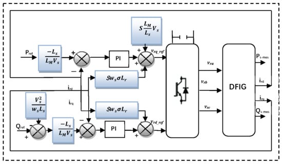
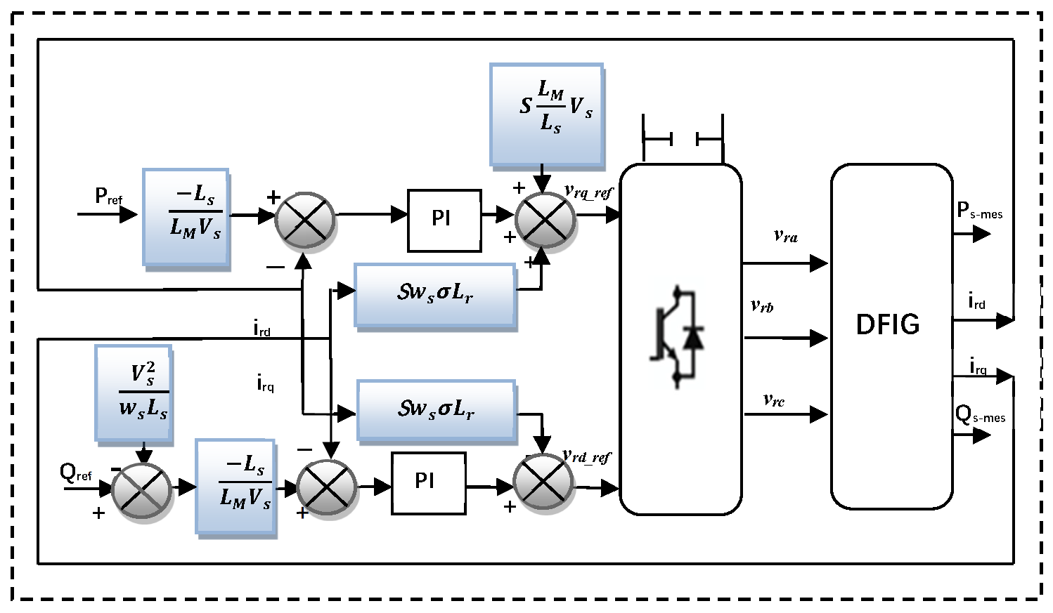
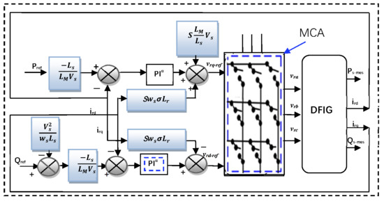
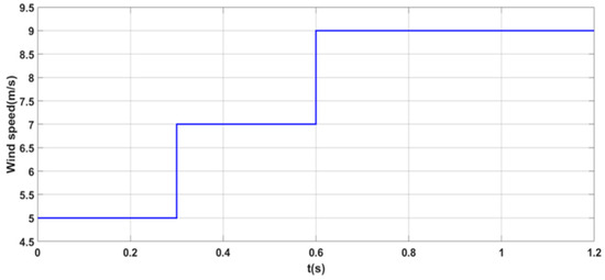
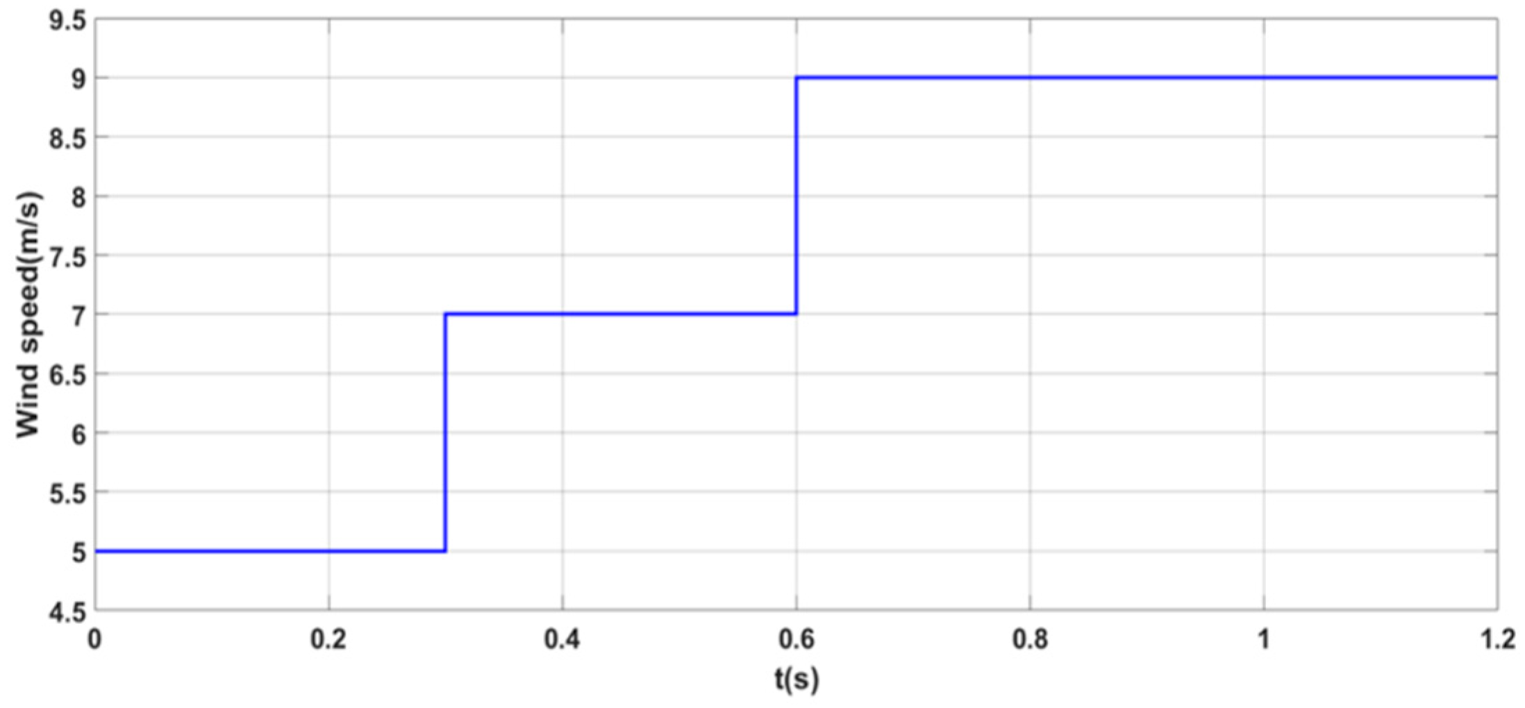
Figure 6 illustrates the power and control diagram of the electromechanical energy conversion system based on a DFIG. This system is directly connected to the grid and powered by an MC via the rotor. Independent control of the active and reactive stator power generated by the DFIG rotor is provided by fractional regulators. The simulation was performed in the MATLAB/Simulink environment. Figure 7 shows the wind speed. This graph represents a staircase evolution of wind speed. It models a step-by-step wind profile for performance testing. Each step lasts approximately 0.3 s and increases by 2 m/s.
Figure 6.
Synoptic diagram of indirect control without a power loop.
Figure 7.
Steps WS profile.
Table 2 presents the main electrical and mechanical parameters of the Doubly Fed Induction Generator (DFIG) used in the simulation studies. Table 3 summarises the control gain values associated with the different controller configurations evaluated. Three types of controllers are considered: a two-level inverter with a conventional PI controller; an MC inverter with a PI controller; and a fractional-order PI controller combined with MC. For each controller, the proportional (Kp) and integral (Ki) gains are provided for both the active power (Ps) and reactive power (Qs) control loops. In the fractional-order PI controller case, an additional parameter, α, representing the controller’s fractional order, is included to increase flexibility and improve overall control performance.
Table 2.
DFIG parameters.
Table 3.
Control gain values.
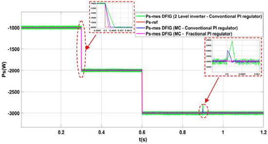
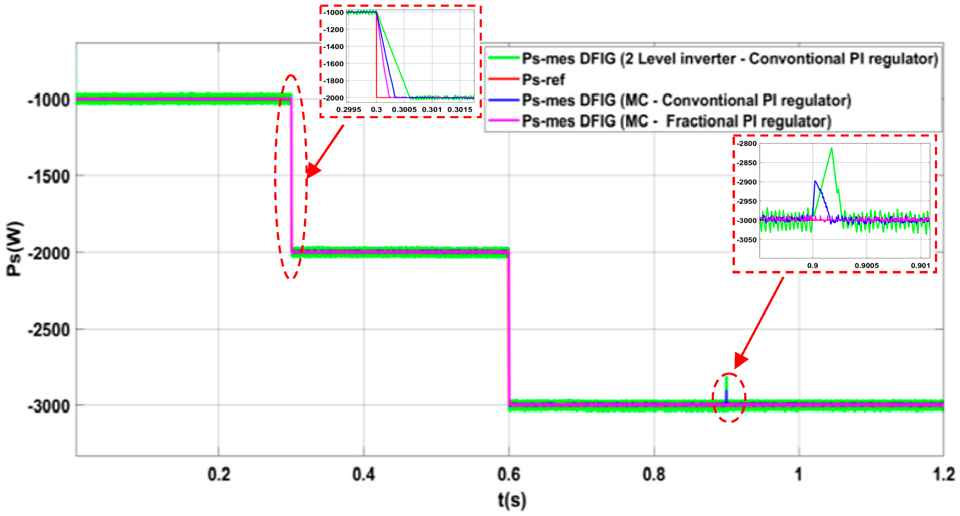
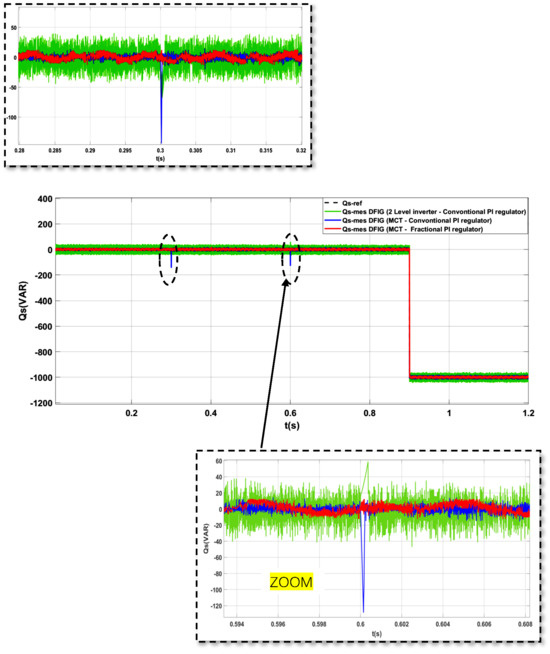
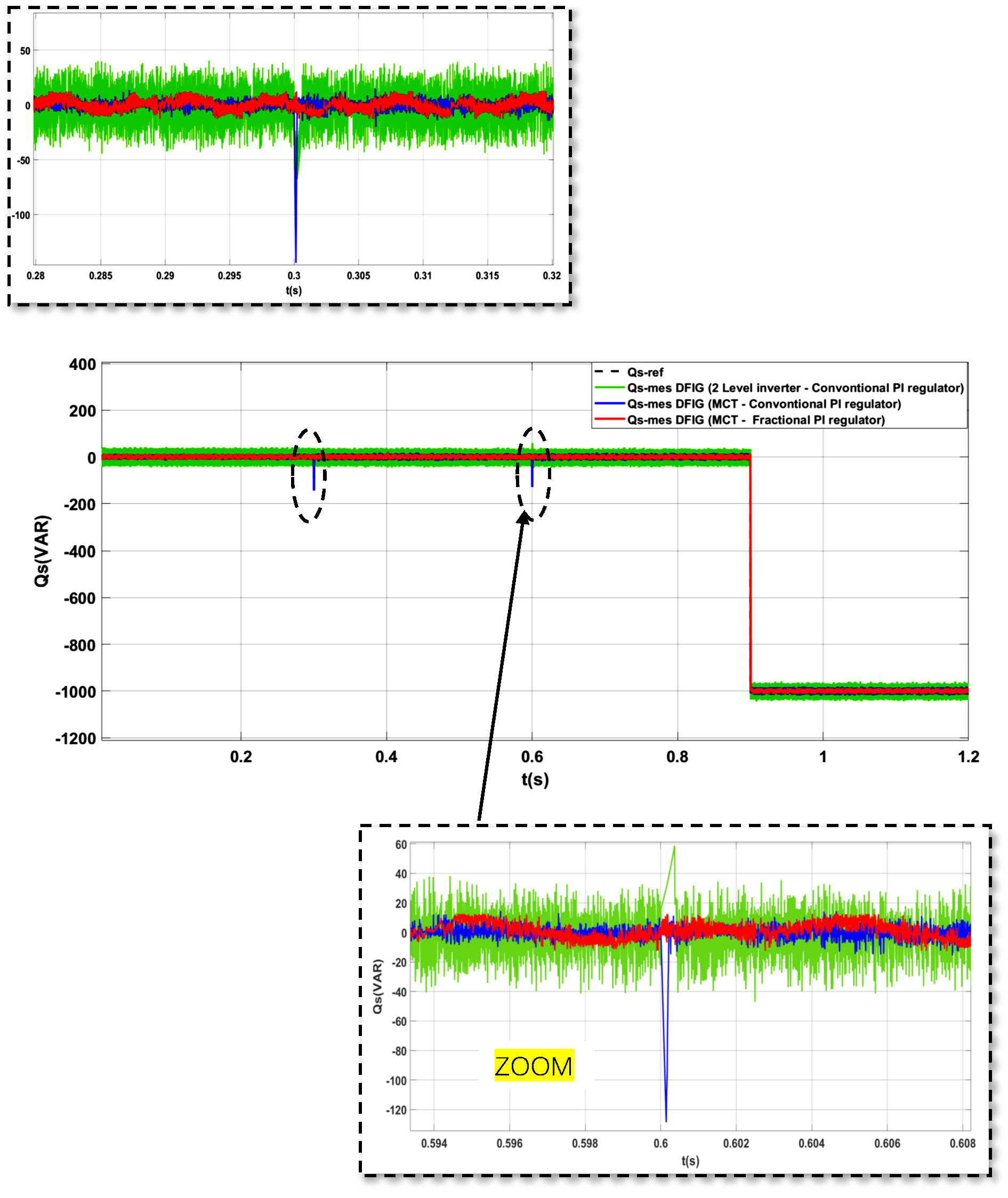
Figure 8 and Figure 9 illustrate the performance tests of the DFIG’s active and reactive power responses under three different power-electronics and control configurations. In the first test, the DFIG is supplied by a two-level PWM inverter, and active and reactive power control is achieved using conventional PI regulators. In the second test, the DFIG is powered by a current-modulated (CM) inverter, which traditional PI regulators still control. In the third test, the power supply is provided by the MC inverter, but this time the control strategy is based on fractional-order PI regulators. When progressive variations in the reference powers (P-ref and Q-ref) are applied, the results show that, for the first two configurations using conventional PI regulators, changes in active power at t = 0.3 s and t = 0.6 s cause noticeable disturbances before the signals return to their reference values. A similar behaviour is observed when the reactive power is modified at t = 0.9 s, indicating a limited decoupling between active and reactive power. In contrast, for the configuration using the MC inverter combined with fractional-order PI regulators, the active and reactive power measurements track their reference values much more accurately. The changes in active power at t = 0.3 s and t = 0.6 s have no noticeable influence on the reactive power, and the change in reactive power at t = 0.9 s does not affect the active power. This clearly demonstrates both the efficiency of the fractional-order control strategy and the robustness of the active/reactive power decoupling.
Figure 8.
Active power control for: a two-level inverter with a conventional PI controller; an MC inverter with a PI controller, and a fractional-order PI controller combined with MC.
Figure 9.
Reactive power control for: a two-level inverter with a conventional PI controller; an MC inverter with a PI controller, and a fractional-order PI controller combined with MC.
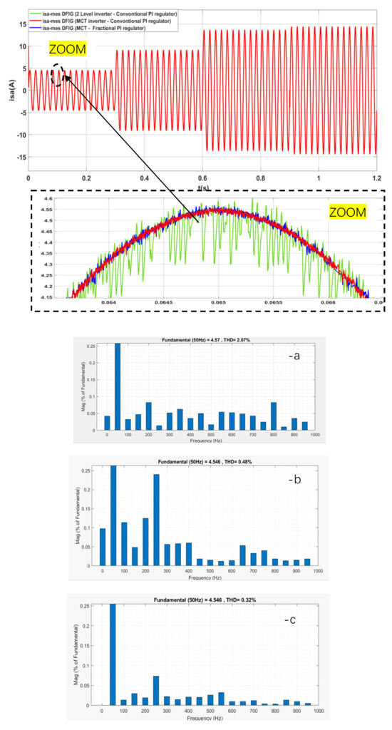
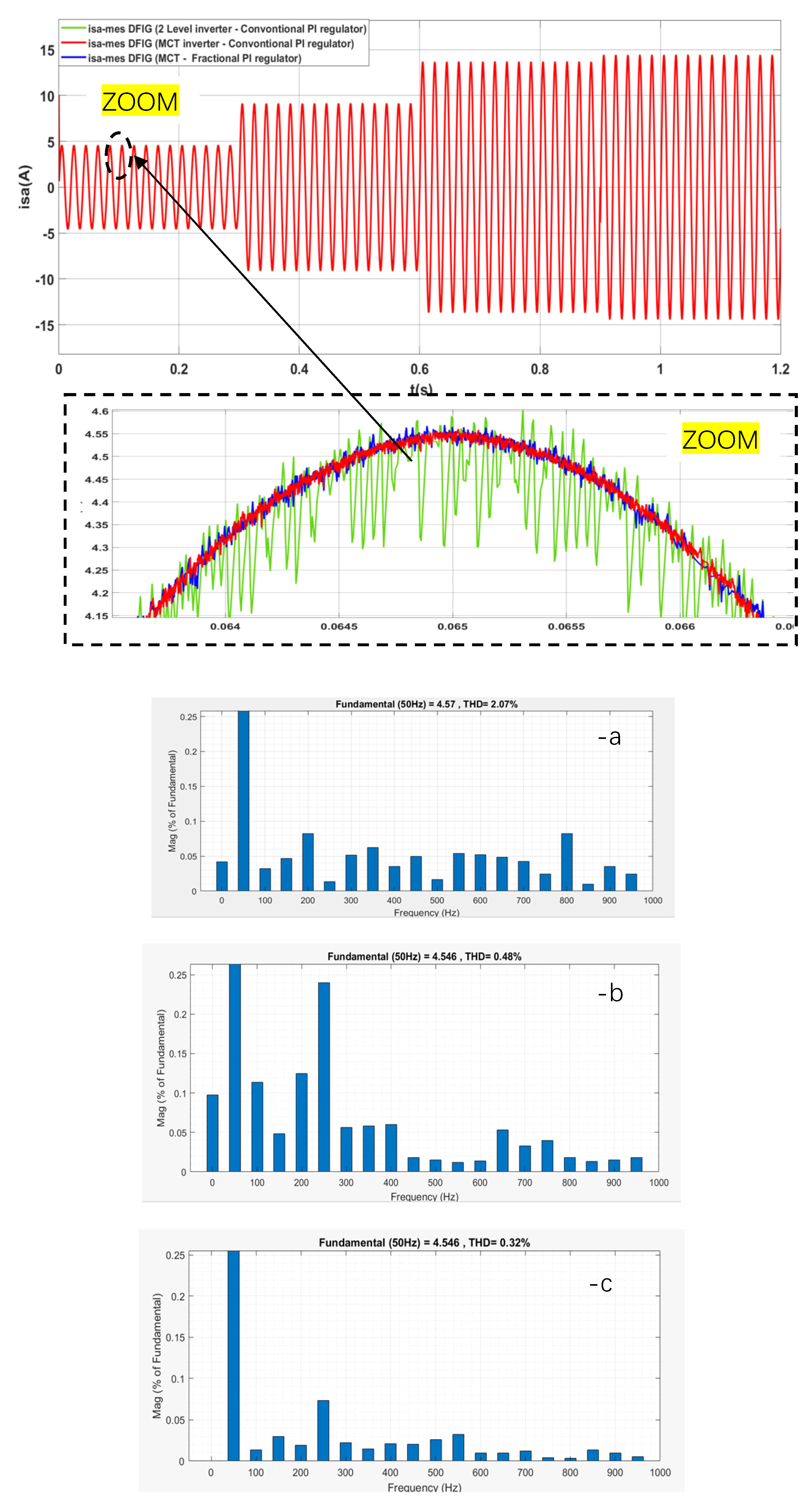
Figure 10 shows the variations in stator currents and voltage. For the first case (a), where the DFIG is powered by a conventional two-level inverter controlled by PI regulators, the current waveform shows noticeable distortions. The frequency analysis confirms the presence of significant harmonic components, resulting in a relatively high THD. In the second case (b), using a matrix converter (MC) combined with conventional PI regulators, the stator current becomes more sinusoidal. The harmonic spectrum indicates a considerable reduction in parasitic components, resulting in lower THD than with the two-level inverter. The third case (c) corresponds to a DFIG supplied by a matrix converter and controlled with fractional-order regulators. This configuration yields the best performance: the stator current is nearly sinusoidal, and the harmonic spectrum shows a significant attenuation of higher-order harmonics. Overall, these results clearly demonstrate that integrating a matrix converter with fractional-order controllers yields superior current quality compared with conventional methods. This improvement enhances the system’s dynamic response, improves power quality, and helps ensure compliance with grid code requirements.
Figure 10.
The stator current delivered by the DFIG for the three tests and their THD for the period 0:0.3 s (Ps-ref = −1000 W and Qs-ref = 0 VAR).
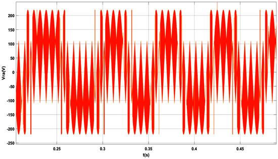
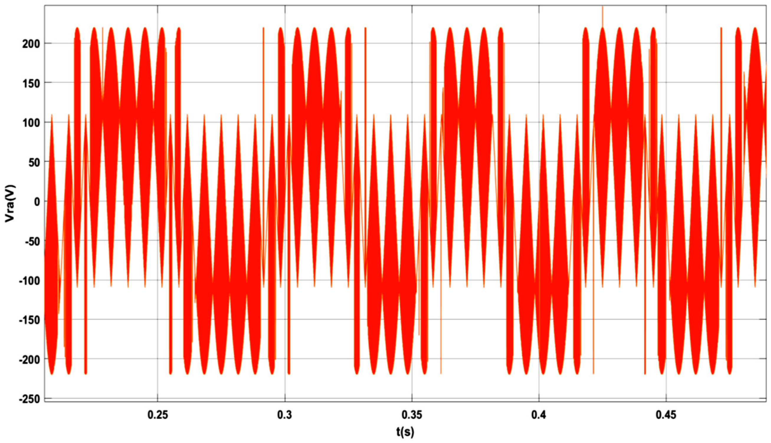
Figure 11 represents the rotor voltage at the output of the matrix converter in the DFIG-based wind system. The smooth voltage waveform indicates that the matrix converter ensures effective synchronisation of the rotor with the grid. The absence of significant fluctuations or spikes demonstrates the converter’s ability to maintain stable operation without requiring an intermediate DC link. This result confirms that the matrix converter enhances system reliability and efficiency, providing better voltage regulation compared to traditional AC-DC-AC converters, which often introduce additional losses and complexity.
Figure 11.
Rotor voltage at the output of matrix converter.
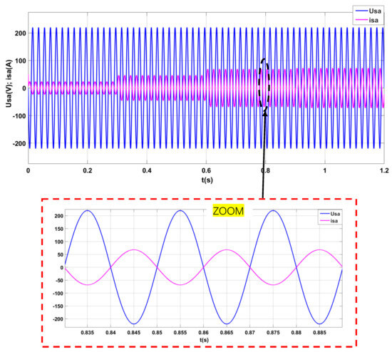
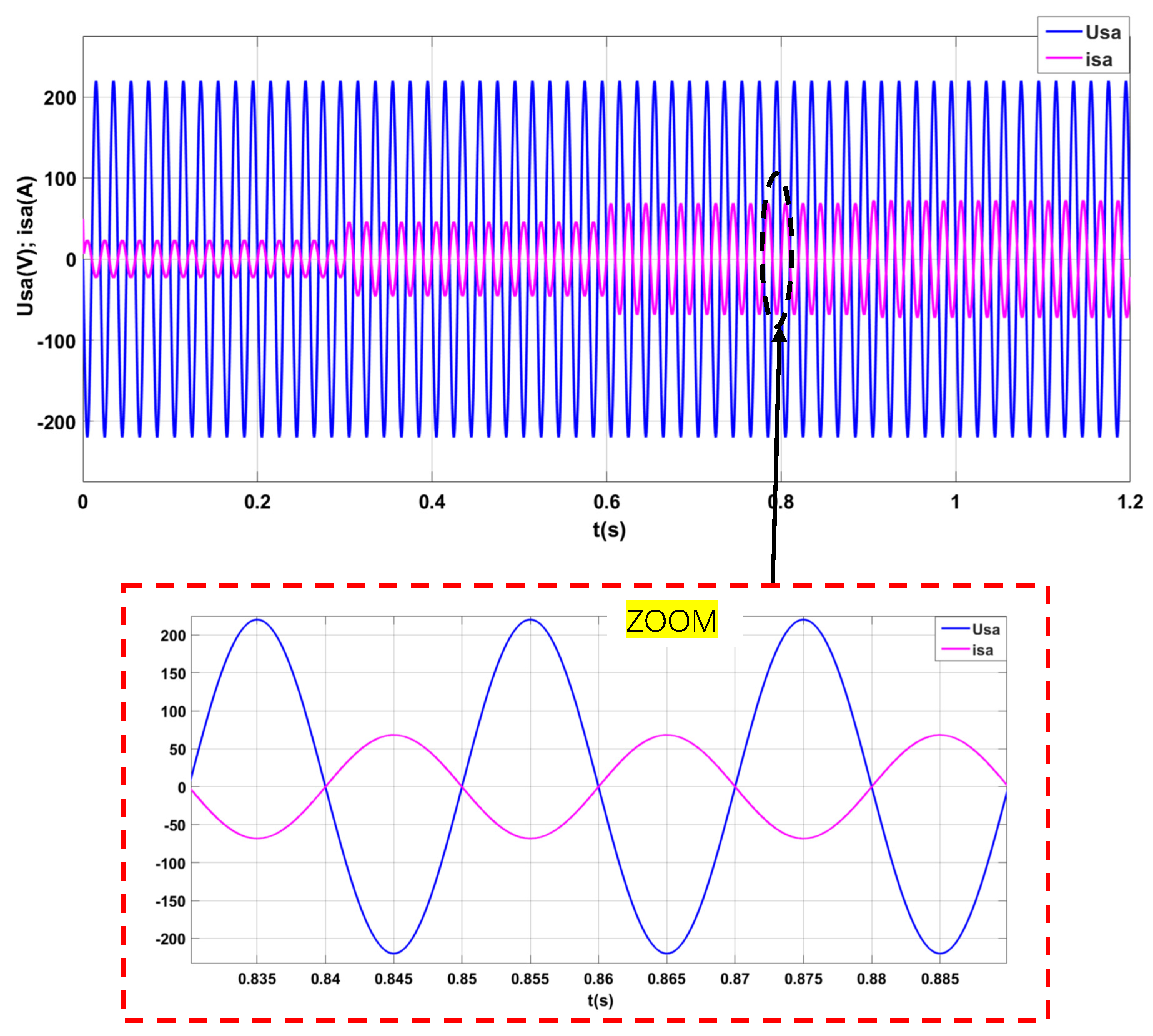
Figure 12 compares the stator current and voltage profiles under matrix converter control. The matrix converter’s ability to smooth the current and voltage waveforms results in significantly reduced total harmonic distortion (THD) compared to conventional control systems. This reduction in THD improves the overall power quality delivered to the grid, ensuring better system performance and compliance with grid standards. By minimising harmonic distortion, the matrix converter-based control system also helps reduce mechanical stress on system components, contributing to the longevity and efficiency of the wind energy conversion system.
Figure 12.
Stator current and voltage comparison.
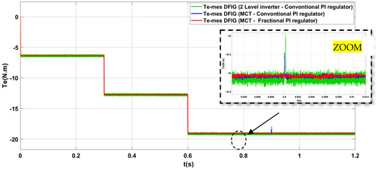
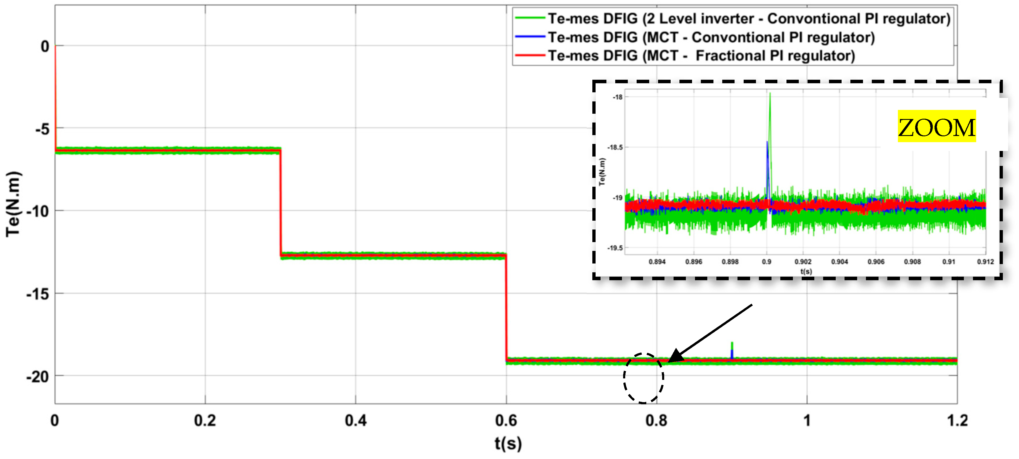
Figure 13 shows the electromagnetic torque (Te) response of the DFIG under three different control configurations: (green) two-level inverter with conventional PI controller, (blue) matrix converter (MCT) with conventional PI controller, and (red) matrix converter (MCT) with fractional PI controller. The fractional-order controller (red) offers the smoothest and most stable torque output, with minimal fluctuations. This indicates a significant improvement in dynamic performance over the conventional control strategies. In contrast, the two-level inverter and matrix converter with conventional PI control (green and blue) show more significant torque fluctuations, highlighting the superior stability and response of the fractional control strategy.
Figure 13.
Electromagnetic torque (Te) response.
Table 4 presents a compa control strategies applied to DFIG systems: (a) a two-level inverter with a conventional PI controller, (b) a current modulation (CM) inverter with a conventional PI controller, and (c) a CM inverter associated with a fractional-order PI controller. The comparison focuses on active and reactive power oscillations, response time, stator current amplitude, and total harmonic distortion (THD%). During the various power set point transitions (from 0 to 0.3 s, from 0.3 to 0.6 s, from 0.6 to 0.9 s, and from 0.9 to 1.2 s), the two-level inverter with a conventional PI controller exhibits the largest active power oscillations, reaching 52 to 72 W depending on the transition, and the slowest response (0.64: 1.32 s), accompanied by the largest reactive power deviation during the reference stage and the highest THD values (THD% = 2.07: 0.66%), indicating lower dynamic performance and inferior power quality. The CM inverter with a conventional PI controller improves active and reactive power tracking, reducing oscillations to 18:25 W, with moderately faster settling times (0.63:0.38 s) and improved harmonic distortion (THD% = 0.46:0.20%), but still exhibits moderate transient deviations. In contrast, the CM inverter combined with a fractional-order PI controller achieves the best overall performance, with minimal active and reactive power oscillations reduced to 7.3:5 W, the fastest settling times (0.46:0.2 s), and the lowest THD levels (THD% = 0.32:0.16%). This demonstrates that fractional-order control offers superior dynamic behaviour and improved power quality.
Table 4.
The performance of three different control strategies for DFIG systems.
Table 5 shows the results of a robustness test performed under different control strategies (two-level inverter with classical PI controllers, matrix converter (MC) with PI controllers, and matrix converter with fractional PI controllers) for varying time periods. The test involves a rotor resistance increase of 100% and a 20% decrease in rotor coil resistance. The table highlights the key performance indicators for each strategy, including reference and measured active power (P-ref and Pmes), reactive power (Q-ref and Qmes), oscillation rates in active and reactive power (ΔP and ΔQ), and the total harmonic distortion (THD) in the stator current.
Table 5.
Robustness test-rotor resistance increased by 100% and rotor coil resistance decreased by 20%.
From the table, we can see that the matrix converter with fractional PI controllers consistently offers the lowest THD across all periods (ranging from 0.58% to 0.24%), indicating superior power quality and reduced harmonic distortion. In comparison, the two-level inverter with classical PI controllers results in significantly higher THD (ranging from 20.07% to 6.24%), demonstrating that traditional controllers generate more harmonics, which can reduce system efficiency and increase mechanical stress on the system. The matrix converter with classical PI controllers performs better than the two-level inverter but still shows higher THD compared to the fractional PI controllers.
Despite the promising simulation results, several practical implementation challenges should be considered. Matrix converters require more bidirectional switches and complex commutation strategies to avoid short-circuit and open-circuit conditions, thereby increasing hardware complexity and control requirements. In addition, the implementation of fractional-order regulators relies on numerical approximation techniques, which increase computational burden and memory usage in real-time applications.
Therefore, the proposed approach is particularly suitable for high-performance wind energy systems equipped with advanced digital control platforms. Future work will focus on experimental validation and on enhancing robustness under realistic operating conditions.
6. Conclusions
This paper presented an indirect power control strategy for DFIG-based wind energy systems using a matrix converter associated with a fractional-order PI controller. The proposed scheme was modelled and evaluated in Matlab/Simulink and compared with three conventional configurations: a two-level PWM inverter with classical PI control; a CM inverter with classical PI control, and a CM inverter with a fractional PI. The three comparison configurations were selected to ensure a representative and systematic evaluation. Specifically, Configuration, a two-level PWM inverter with classical PI control, represents a widely adopted conventional control scheme in practical applications. Configuration, a CM inverter with classical PI control, reflects an advanced strategy reported in the recent literature and corresponds to the proposed method.
Simulation results demonstrate a clear enhancement in dynamic performance and power quality. Compared with the conventional two-level inverter, the proposed approach reduces active power oscillations from 52–72 W to 5–7.3 W (≈85–90% reduction) and shortens the settling time from 0.64–1.32 s to 0.2–0.46 s (up to 70% faster response). In addition, THD is reduced from 2.07% to 0.16%, representing nearly a 90% improvement in harmonic performance. Even compared to the CM inverter with classical PI control, the fractional-order strategy achieves about 60% lower power oscillations, up to 50% faster settling time, and around 30% lower THD. These results confirm that the matrix converter–fractional PI scheme significantly improves both transient response and power quality, making it a promising and energy-efficient solution for next-generation DFIG wind energy conversion systems. Future work will focus on experimental validation and large-scale implementation [40,41].
Author Contributions
The authors confirm their contribution to the article as follows. The first author, S.G., contributed to the conceptualisation, formal analysis, methodology, validation, resource acquisition, investigation, data curation, software development, and writing of the original draft. A.D. (Azzeddine Dekhane); M.F. and A.D. (Abdelhak Djellad) contributed to the writing of the original draft, data curation, methodology, formal analysis, and validation. M.T. and A.A.-Q. contributed to supervision, conceptualisation, visualisation, resource acquisition, data curation, and validation. All authors have read and approved the final manuscript.
Funding
This research received no external funding.
Data Availability Statement
The original contributions presented in this study are included in the article. Further inquiries can be directed to the corresponding author.
Conflicts of Interest
The authors declare that they have no conflicts of interest to report regarding the present study.
References
- Ibrahim, R.A.; Zakzouk, N.E. A PMSG Wind Energy System Featuring Low-Voltage Ride-through via Mode-Shift Control. Appl. Sci. 2022, 12, 964. [Google Scholar] [CrossRef] [Scilit]
- Wang, Y.; Ji, H.; Luo, R.; Liu, B.; Wu, Y. Energy Optimization Strategy for Wind–Solar–Storage Systems with a Storage Battery Configuration. Mathematics 2025, 13, 1755. [Google Scholar] [CrossRef] [Scilit]
- Sahri, Y.; Tamalouzt, S.; Lalouni, S.B. Enhanced Direct Power Control Strategy of a DFIG-Based Wind Energy Conversion System Operating Under Random Conditions. Period. Polytech. Electr. Eng. Comput. Sci. 2021, 65, 196–206. [Google Scholar] [CrossRef] [Scilit]
- Campos-Gaona, D.; Stock, A.; Anaya-Lara, O.; Leithead, W. Dynamic Wind Power Plant Control for System Integration Using the Generator Response Following Concept. Energies 2020, 13, 1804. [Google Scholar] [CrossRef] [Scilit]
- Chang, V.; Chen, Y.; Zhang, Z.; Xu, Q.A.; Baudier, P.; Liu, B.S.C. The market challenge of wind turbine industry-renewable energy in PR China and Germany. Technol. Forecast. Soc. Change 2021, 166, 120631. [Google Scholar] [CrossRef] [Scilit]
- Chojaa, H.; Derouich, A.; Chehaidia, S.E.; Zamzoum, O.; Taoussi, M.; Elouatouat, H. Integral sliding mode control for DFIG based WECS with MPPT based on artificial neural network under a real wind profile. Energy Rep. 2021, 7, 4809–4824. [Google Scholar] [CrossRef] [Scilit]
- Bouraiou, A.; Dekhane, A.; Slimani, A.; Rouabhia, A.; Neçaibia, A.; Dahbi, A.; Lachtar, S.; Boutasseta, N.; Sakher, E. Windscapes of Algeria: Assessing Potential, Challenges, and Future Prospects in Renewable Energy. In Proceedings of the 2023 14th International Renewable Energy Congress (IREC), Sousse, Tunisia, 16–18 December 2023; pp. 1–5. [Google Scholar]
- Ghoudelbourk, S.; Dib, D.; Omeiri, A. New techniques to improve the power control in the double-fed induction generator wind turbine. Wind Eng. 2016, 40, 86–99. [Google Scholar] [CrossRef] [Scilit]
- Rekik, B.; Dekhane, A.; Djellad, A.; Bouderres, N.; Benamira, N.; Soltana, A. Performance Comparison of PI, Fuzzy Logic, and Sliding Mode Controls for Wind Turbine Power Management. J. Eur. Syst. Autom. 2024, 57, 127–135. [Google Scholar] [CrossRef] [Scilit]
- Hosseini, S.M.H.; Rezvani, A. Modeling and simulation to optimize direct power control of DFIG in variable-speed pumped-storage power plant using teaching–learning-based optimization technique. Soft Comput. 2020, 24, 16895–16915. [Google Scholar] [CrossRef] [Scilit]
- Thangavel, M.K.; Ramasamy, B.K.; Ponnusamy, P. Performance Analysis of Dual Space Vector Modulation Technique-Based Quasi Z-Source Direct Matrix Converter. Electr. Power Compon. Syst. 2020, 48, 1185–1196. [Google Scholar] [CrossRef] [Scilit]
- Ait-Chekdhidh, Z.; Ardjal, A.; Bettayeb, M. Funnel control based super-twisting sliding mode control of wind turbines. J. King Saud Univ.—Eng. Sci. 2025, 37, 25. [Google Scholar] [CrossRef] [Scilit]
- Zhang, J.; Wan, Y.; Ouyang, Q.; Dong, M. Nonlinear Stochastic Adaptive Control for DFIG-Based Wind Generation System. Energies 2023, 16, 5654. [Google Scholar] [CrossRef] [Scilit]
- Assabaa, M.; Bouchahed, A.; Draidi, A.; Hammoudi, S. Fractional order PIλDµ controller for hybrid tank system control. Stud. Eng. Exact Sci. 2024, 5, e11896. [Google Scholar] [CrossRef] [Scilit]
- Sami, I.; Ullah, S.; Khan, L.; Al-Durra, A.; Ro, J.-S. Integer and Fractional-Order Sliding Mode Control Schemes in Wind Energy Conversion Systems: Comprehensive Review, Comparison, and Technical Insight. Fractal Fract. 2022, 6, 447. [Google Scholar] [CrossRef] [Scilit]
- Tewari, S.; Gupta, R.K.; Mohan, N. Three-level indirect matrix converter based open-end winding AC machine drive. In Proceedings of the IECON 2011—37th Annual Conference of the IEEE Industrial Electronics Society, Melbourne, VIC, Australia, 7–10 November 2011; pp. 1636–1641. [Google Scholar]
- Yin, L.; Lai, L.; Zhu, Z.; Li, T. Maximum Power Point Tracking Control for Non-Gaussian Wind Energy Conversion System by Using Survival Information Potential. Entropy 2022, 24, 818. [Google Scholar] [CrossRef] [Scilit] [PubMed]
- Poitiers, F.; Bouaouiche, T.; Machmoum, M. Advanced control of a doubly-fed induction generator for wind energy conversion. Electr. Power Syst. Res. 2009, 79, 1085–1096. [Google Scholar] [CrossRef] [Scilit]
- Hore, D.; Sarma, R. Neural network–based improved active and reactive power control of wind-driven double fed induction generator under varying operating conditions. Wind Eng. 2018, 42, 381–396. [Google Scholar] [CrossRef] [Scilit]
- Yan, C.; Yao, W.; Wen, J.; Fang, J.; Ai, X.; Wen, J. Modelling and comparison analysis of grid-connected DFIG-based wind farm in weak grid. IET Renew. Power Gener. 2020, 14, 2406–2415. [Google Scholar] [CrossRef] [Scilit]
- Achar, A.; Djeriri, Y.; Benbouhenni, H.; Bouddou, R.; Elbarbary, Z.M.S. Modified Vector-Controlled DFIG Wind Energy System Using Robust Model Predictive Rotor Current Control. Arab. J. Sci. Eng. 2025, 50, 11065–11089. [Google Scholar] [CrossRef] [Scilit]
- Lopez-Garcia, I.; Lopez-Monsalvo, C.S.; Gomez-Gonzalez, O.; Sanabria-Villamizar, M.; Beltran-Carbajal, F.; Escarela-Perez, R. On the Regulation of Wind Energy Conversion Systems Working as Conventional Generation Plants. Mathematics 2023, 11, 2495. [Google Scholar] [CrossRef] [Scilit]
- Cuesta, A.B.; Gomez-Gil, F.J.; Fraile, J.V.M.; Rodríguez, J.A.; Calvo, J.R.; Vara, J.P. Feasibility of a Simple Small Wind Turbine with Variable-Speed Regulation Made of Commercial Components. Energies 2013, 6, 3373–3391. [Google Scholar] [CrossRef] [Scilit]
- Ye, Y.; Yang, Z.; Hu, J.; Yi, H.; Zhang, L. Control Strategy of Doubly-Fed Induction Generator under Zero Voltage Fault of Power Grid. Sustainability 2022, 14, 15835. [Google Scholar] [CrossRef] [Scilit]
- Sáiz-Marín, E.; Zarei, M.E.; Medina, D.; Curbelo, Ó.; Babiano, A.M.; Berrueta, A.; Ursúa, A.; Sanchis, P. Doubly Fed Induction Generator Robust Design for Avoiding Converter-Driven Instability: Perspective. Energies 2025, 18, 2736. [Google Scholar] [CrossRef] [Scilit]
- Alilou, M.; Azami, H.; Oshnoei, A.; Mohammadi-Ivatloo, B.; Teodorescu, R. Fractional-Order Control Techniques for Renewable Energy and Energy-Storage-Integrated Power Systems: A Review. Fractal Fract. 2023, 7, 391. [Google Scholar] [CrossRef] [Scilit]
- Ali, M.; Kotb, H.; Aboras, K.M.; Abbasy, N.H. Design of Cascaded PI-Fractional Order PID Controller for Improving the Frequency Response of Hybrid Microgrid System Using Gorilla Troops Optimizer. IEEE Access 2021, 9, 150715–150732. [Google Scholar] [CrossRef] [Scilit]
- Magdy, F.E.Z.; Hasanien, H.M.; Sabry, W.; Ullah, Z.; Alkuhayli, A.; Yakout, A.H. Mountain Gazelle Algorithm-Based Optimal Control Strategy for Improving LVRT Capability of Grid-Tied Wind Power Stations. IEEE Access 2023, 11, 129479–129492. [Google Scholar] [CrossRef] [Scilit]
- Charef, A.; Sun, H.H.; Tsao, Y.Y.; Onaral, B. Fractal system as represented by singularity function. IEEE Trans. Autom. Control 1992, 37, 1465–1470. [Google Scholar] [CrossRef] [Scilit]
- Djouambi, A.; Charef, A.; Voda, A. Fractional order controller based on bode’s ideal transfer function. Mechatron. Syst. Control Former. Control Intell. Syst. 2010, 2010, 38. [Google Scholar] [CrossRef] [Scilit]
- Jenifer Suriya, L.J.; Christy Mano Raj, J.S. DBN-Based MPPT Algorithm with FOPID Control for Optimal Power Tracking, Reliability, and Efficiency in Solar PV Systems under Shaded Conditions. Maint. Reliab. 2025, 27. [Google Scholar] [CrossRef] [Scilit]
- Yessef, M.; Benbouhenni, H.; Lagrioui, A.; Bizon, N.; Bossoufi, B.; Al-Gahtani, S.F.; Elbarbary, Z.M.S. Processor-in-the-Loop validation of direct power control based on fractional-order modified super-twisting algorithm for doubly-fed induction generators. Sci. Rep. 2025, 15, 22846. [Google Scholar] [CrossRef] [Scilit]
- Aslam, M.S.; Raja, M.A.Z. A new adaptive strategy to improve online secondary path modeling in active noise control systems using fractional signal processing approach. Signal Process. 2015, 107, 433–443. [Google Scholar] [CrossRef] [Scilit]
- Chaoui, H.; Hamane, B.; Doumbia, M.L. Adaptive Control of Venturini Modulation Based Matrix Converters Using Interval Type-2 Fuzzy Sets. J. Control Autom. Electr. Syst. 2016, 27, 132–143. [Google Scholar] [CrossRef] [Scilit]
- Djellad, A.; Belakehal, S.; Chenni, R.; Dekhane, A. Reliability Improvement in Serial Multicellular Converters Based on STATCOM Control. J. Eur. Syst. Autom. 2021, 54, 519–528. [Google Scholar] [CrossRef] [Scilit]
- Blouh, F.; Boujidi, B.; Bezza, M. Wind energy conversion system based on DFIG using three-phase AC-AC matrix converter. Int. J. Power Electron. Drive Syst. IJPEDS 2023, 14, 1865–1875. [Google Scholar] [CrossRef] [Scilit]
- von Jouanne, A.; Agamloh, E.; Yokochi, A. A Review of Matrix Converters in Motor Drive Applications. Energies 2025, 18, 164. [Google Scholar] [CrossRef] [Scilit]
- Mondal, S.; Kastha, D. Maximum Active and Reactive Power Capability of a Matrix Converter-Fed DFIG-Based Wind Energy Conversion System. IEEE J. Emerg. Sel. Top. Power Electron. 2017, 5, 1322–1333. [Google Scholar] [CrossRef] [Scilit]
- Gulbudak, O.; Gokdag, M.; Komurcugil, H. Dual-sliding mode control of nine-switch inverter. Int. Trans. Electr. Energy Syst. 2021, 31, e13185. [Google Scholar] [CrossRef] [Scilit]
- Dekhane, A.; Mohamed Foued, G.; Djellabi, R.; Djellad, A.; Benamira, N. Real Large-Scale Waste Management and Electricity Generation by Incineration and Methanation Routes: Methodologies and Comparative Investigation on Local Municipal Waste Landfills. Iran. J. Chem. Chem. Eng. 2024, 43, 3427–3437. [Google Scholar] [CrossRef] [Scilit]
- Farhat, M.; Dekhane, A.; Djellad, A.; Takruri, M.; Al-Qaisi, A.; Barambones, O. Optimizing photovoltaic performance: Data-driven maximum power point prediction via advanced regression models. Results Control Optim. 2025, 20, 100586. [Google Scholar] [CrossRef] [Scilit]

Disclaimer/Publisher’s Note: The statements, opinions and data contained in all publications are solely those of the individual author(s) and contributor(s) and not of MDPI and/or the editor(s). MDPI and/or the editor(s) disclaim responsibility for any injury to people or property resulting from any ideas, methods, instructions or products referred to in the content. |
© 2026 by the authors. Licensee MDPI, Basel, Switzerland. This article is an open access article distributed under the terms and conditions of the Creative Commons Attribution (CC BY) license.