


Abstract
To meet the requirements for the automatic alignment, insertion, and inspection of guide-tube opening pins on the upper core plate in a component pool during refueling outages of nuclear power units, this paper proposes a cognition-enhanced visual-servoing framework that integrates geometric cognition-based compensation, observation-confidence modeling, and constraint-aware optimal control. The framework addresses the key challenge posed by the coexistence of long-term geometric drift and underwater observation uncertainty. Specifically, historical closed-loop data are leveraged to learn and compensate for systematic geometric errors online, substantially improving coarse-positioning accuracy. In addition, an explicit confidence model is introduced to quantitatively assess the reliability of visual measurements. Building on these components, a confidence-driven, finite-horizon, constrained model predictive control strategy is designed to achieve safe and efficient finite-step convergence while strictly respecting actuator physical constraints. Ground experiments and deep-water component-pool validations demonstrate that the proposed method reduces coarse-positioning error by approximately 75%, achieves stable sub-millimeter alignment with an ample engineering safety margin, and effectively decreases erroneous insertions and the need for manual intervention. These results confirm the engineering applicability and safety advantages of the proposed cognition-enhanced visual-servoing framework for underwater alignment tasks in nuclear component pools.
1. Introduction
The structural integrity of reactor internals is directly tied to the operational safety and reliability of nuclear power units [1,2,3]. During refueling outages and other critical maintenance windows, inspection, alignment, and insertion operations associated with the guide-tube opening pins on the upper core plate are performed frequently and entail elevated risk [4,5]. To reduce personnel radiation exposure and improve operational consistency, deploying mobile robotic systems equipped with vision sensors and actuation mechanisms to conduct automated inspection and insertion in the spent-fuel pool environment has become an important area of focus in nuclear maintenance engineering [6,7,8]. However, underwater operations in component pools pose distinct challenges for automation. Light scattering and refraction in water, together with suspended particulates, can severely degrade underwater image quality [9,10,11]. Meanwhile, assembly tolerances and long-term operational drift gradually alter the geometric relationship among the camera, linear stages, and core plate, causing deviations from the nominal kinematic model [12,13]. The coupling of observation uncertainty and geometric mismatch can readily lead to jamming during automatic alignment/insertion, and, in the worst case, increase the risk of structural damage [14]. Therefore, for underwater alignment tasks in component pools, there is a pressing need for an automated method that explicitly accounts for both sensing uncertainty and geometric error while maintaining high accuracy, interpretability, and operational safety.
For industrial visual-servoing tasks, existing studies typically establish camera–workpiece geometric models through camera calibration [15], object detection [16], and pose estimation [17]. In scenarios with high assembly accuracy and a limited workspace, these approaches can provide acceptable initial localization accuracy. However, component-pool environments often exhibit assembly misalignment and long-term thermal/mechanical drift, which gradually alter the geometric relationship over time [18]. As a result, a one-time static calibration cannot remain effective over the long term and may introduce a consistent coarse-positioning bias across the entire workspace. To further mitigate such errors, He et al. introduced a self-calibration scheme [19]. These approaches, however, often rely on additional sensors, a large amount of calibration data, or strong assumptions about scene geometry, making them difficult to apply under maintenance constraints that require “minimal calibration and rapid recovery”.
Underwater imaging is highly susceptible to scattering, refraction, and suspended particles, which often lead to low contrast, blurring, and noise [20]. Song enhanced single-frame recognition performance by integrating image enhancement, object detection, and pose estimation [21]. In component-pool operations, however, local image quality varies significantly with depth, illumination, and water conditions, leading to large fluctuations in measurement reliability across different operating conditions. Sadjoli modeled the error as zero-mean random noise and relied on fixed-gain feedback to attenuate it [22]. Such methods rarely provide an explicit measure of whether the current observation is trustworthy, nor do they exploit observation quality in control decisions, which increases the risk of false convergence or unsafe actions under extreme conditions.
Industrial visual servoing commonly achieves closed-loop convergence using proportional/PD control or image-Jacobian-based control laws [23]. When travel limits, step-size constraints, and insertion safety boundaries are present, fixed-gain control cannot readily balance convergence speed and operational safety [24]. Moreover, under fluctuating measurement quality, many controllers lack perception-quality-driven adaptive decision mechanisms. In contrast, Elmezain employed an end-to-end deep regression approach and demonstrated strong representational capability in certain underwater scenarios [25]. These methods, however, often require large-scale annotations, cross-scene generalization validation, and online interpretability support. Such requirements increase deployment costs and complicate safety verification, making them less suitable for nuclear maintenance tasks that require verifiability and risk control.
Based on engineering experience and the current state of the art, automatic alignment and insertion for upper core-plate opening-pin holes in component pools face three key challenges.
- (1)
- Accumulation of long-term geometric errors: Assembly offsets between the linear stages and the core plate are unavoidable. Moreover, slow drift during long-term operation can invalidate statically calibrated models and induce systematic coarse-positioning errors across the entire workspace.
- (2)
- Uncertain underwater observation quality: Due to underwater optics, local image quality can fluctuate substantially. Consequently, the reliability of single-frame visual measurements varies markedly across operating conditions, whereas conventional methods lack mechanisms to quantify and address this uncertainty.
- (3)
- Insufficient safety in alignment control strategies: Many existing solutions employ fixed-gain proportional or PD control. Under travel and step-size constraints, it is difficult to balance convergence speed and operational safety, and the controller cannot adapt its decisions according to perception quality.
To address these challenges, we organize the centering-and-insertion process into a “cognition–perception–execution” closed-loop framework on an integrated robot–three-axis stage–camera/probe platform. Specifically, the main contributions of this paper are as follows:
- (1)
- At the geometric level, to address long-term geometric error accumulation, we propose a global translation self-calibration method based on closed-loop residuals from a small set of calibration holes. We further introduce a continuously updated planar error-field model for prior compensation, which significantly reduces coarse-positioning bias before the visual-servo loop is engaged.
- (2)
- At the perception level, to address uncertainty in underwater observation quality, we construct an explicit confidence metric during ROI-based pin-hole detection, enabling quantitative characterization of single-frame measurement reliability. We experimentally validate its correlation with planar localization error, thereby establishing it as a quality input for closed-loop control and insertion decisions.
- (3)
- At the execution level, to improve the safety of centering control strategies, we develop a confidence-aware constrained MPC scheme to ensure safe convergence under step-size/travel constraints. We also design a confidence-driven three-state finite-state machine that actively reduces step size or freezes pose updates under low-quality observations, thereby reducing misinsertion risk and improving insertion success rates.
The remainder of this paper is organized as follows. Section 2 introduces the operational scenario, system hardware, and modeling foundations. Section 3 details underwater visual perception, geometric cognition-based compensation, and the proposed constrained visual-servoing method. Section 4 validates the approach through ground and deep-pool experiments. Section 5 concludes the paper and outlines directions for future research.
2. Operational Scenario and System Modeling
2.1. Overview of the Scenario and Platform
The task investigated in this study is the automatic alignment and insertion of the guide-tube opening pins on the upper core plate during refueling outages of nuclear power units, conducted in a component-pool (i.e., spent-fuel pool) environment.
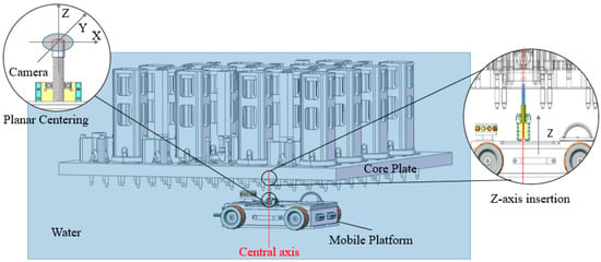
The upper core plate is located on the pool bottom underwater. On its planar surface, the opening-pin holes are arranged in a regular array. In some local regions, there also exist pins of similar size as well as large circular holes and square holes, which introduce background clutter and interference for visual detection. The relative spatial relationship between the component pool and the upper core plate is illustrated in Figure 1. Overall, this operating scenario exhibits typical characteristics, including underwater image degradation, a restricted workspace, and stringent safety requirements for alignment.
Figure 1.
A schematic of the component pool and the integrated robot–linear-stage–camera structure.
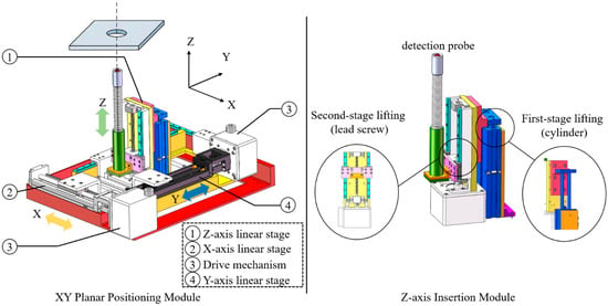
To reduce manual intervention and mitigate radiation exposure risk, this paper adopts an operational scheme of “mobile robot + local precision positioning module.” The mobile robot provides global reachability on the pool bottom, while a three-axis linear stage and an integrated camera/probe end effector mounted on the robot are responsible for local fine alignment and insertion toward the target pinhole. The X/Y axes of the stage perform in-plane alignment adjustment, and the Z axis is used for height regulation and insertion-stroke control.
The visual module is installed coaxially with the Z axis, ensuring that the camera optical axis is approximately perpendicular to the upper-core-plate plane. This configuration simplifies the subsequent mapping from pixel coordinates to physical planar coordinates and facilitates the establishment of the visual-servoing model. The insertion mechanism is shown in Figure 2.
Figure 2.
A structural schematic of the three-axis linear stage and the Z-axis insertion mechanism.
2.2. Coordinate Frames and Kinematic Modeling
To provide a unified description of the geometric relationship among the upper core plate, the three-axis linear stage, and the integrated camera/probe, and to map vision-based measurements into in-plane alignment errors on the core-plate surface, this section defines the coordinate frames used throughout the paper and establishes the basic kinematic model.
2.2.1. Upper-Core-Plate Frame and Stage-Base Frame
A core-plate coordinate frame, denoted by , is defined at the geometric center of the upper core plate. The axes lie on the plate plane and align with the principal directions of the hole array, while the axis is normal to the plate and points upward toward the water surface.
The nominal (design) center of the -th guide-tube opening-pin hole can then be expressed in as
the base frame of the three-axis linear stage is denoted by . Its origin is fixed to the stage base, and its axes coincide with the motion directions of the stage’s linear axes, respectively.
The assembly relationship between the core plate and the stage base is modeled as a constant rigid-body transform
where is the rotation matrix, and is the translation vector of the origin of expressed in .
Ideally, is constant; in practice, it can deviate from its nominal value due to assembly tolerances and long-term operational drift. Introducing this transform allows the stage and end-effector pose to be consistently represented by , which forms the basis for subsequent in-plane positioning-error computation within a unified geometric framework.
2.2.2. Stage Joint Coordinates and End-Effector Pose
Let the generalized coordinate vector of the three-axis linear stage be
where x, y, z are the linear displacements along the X, Y, Z axes of the stage, respectively. The end-effector (camera/probe) frame is denoted by and is rigidly mounted at the end of the Z axis. The axis follows the camera optical axis and points toward the core plate, while the axes are aligned with the pixel axes of the image plane.
Neglecting structural compliance and small mounting imperfections, the forward kinematics from to can be written as the rigid transform
Here, is a constant rotation matrix determined by the mounting orientation of the camera/probe relative to the stage base, and is the position of the end-effector origin expressed in . Since the three axes are independent linear motions, can be expressed as
where is the translation of the end-effector origin relative to at the mechanical home position, obtained via installation calibration.
Combining the core-plate-to-stage-base installation transform with the stage forward kinematics yields the end-effector pose with respect to the core-plate frame:
The translation component of gives the position vector of the end-effector origin in , denoted as .
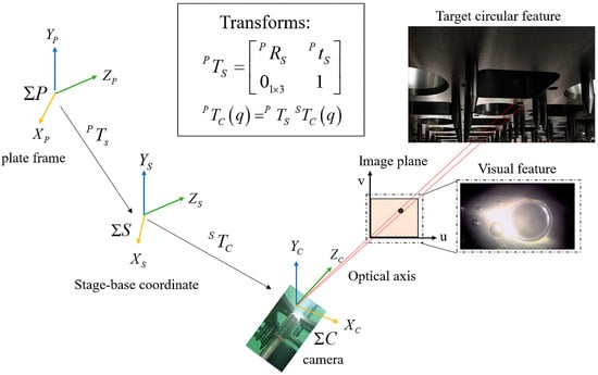
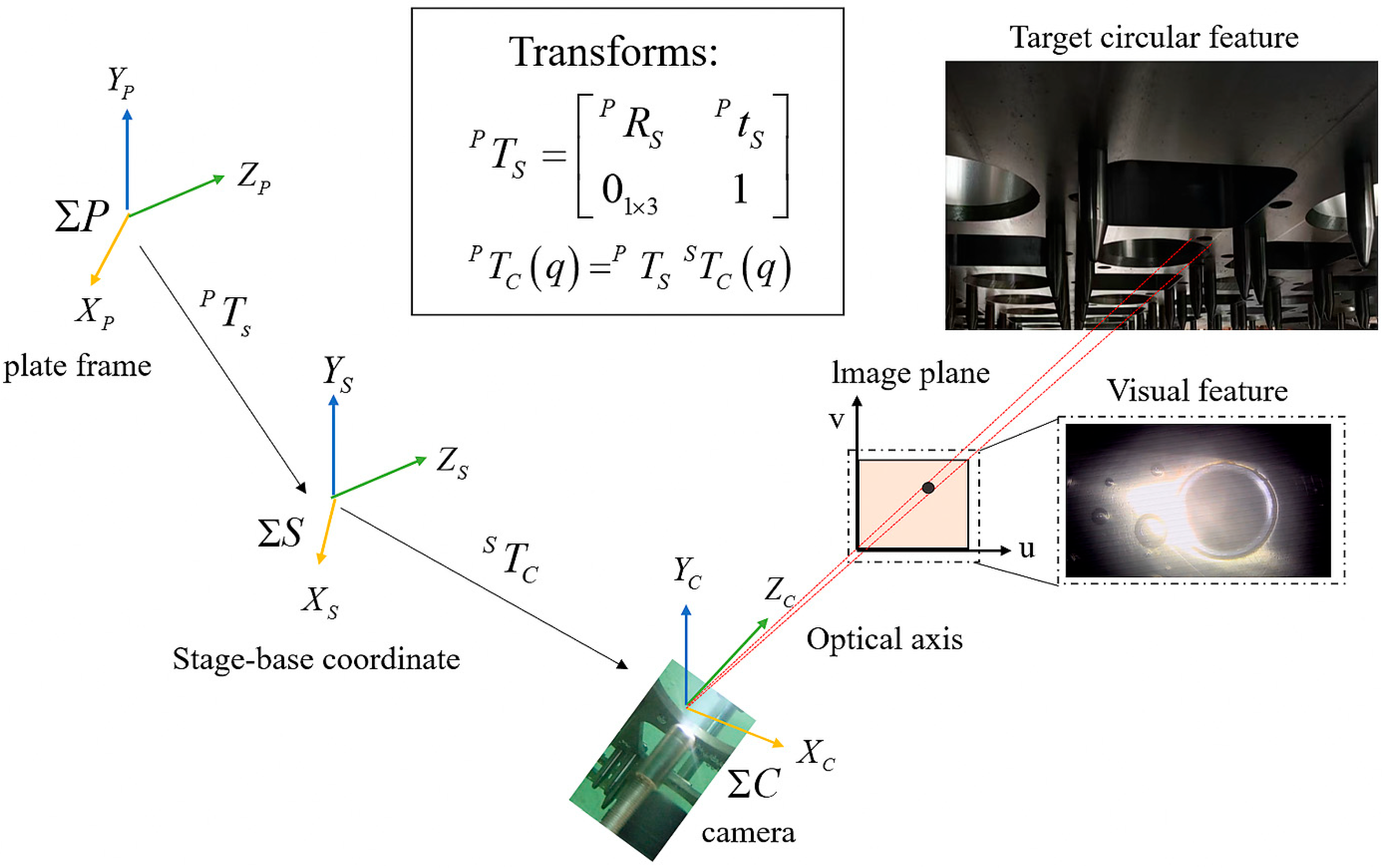
For the alignment task, the design coordinate of the i-th hole is taken as the target. An inverse-kinematics operator provides a corresponding coarse-positioning joint configuration (denoted here as ) to drive the end-effector to the vicinity of the target hole. This coarse result serves as the initial state for the vision feedback-based fine alignment closed loop described in Section 3. The coordinate–frame relationships are illustrated in Figure 3.
Figure 3.
A schematic of the three coordinate frames and their kinematic relationships.
Based on the above kinematic modeling, subsequent sections will incorporate camera calibration parameters to establish an approximate mapping from image pixel coordinates to planar coordinates on the core plate. The in-plane end-effector error will then be expressed as a function of incremental joint motions, providing a unified geometric and mathematical foundation for the cognition-enhanced visual servoing and constrained MPC method proposed in Section 3.
3. Cognition-Enhanced Underwater Visual Localization Method
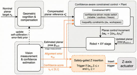
Building on the static geometric model established in Section 2 and targeting the key challenges identified above, this chapter develops an error-field-driven, cognition-enhanced visual-servoing framework together with a constrained MPC strategy. The overall architecture is shown in Figure 4.
Figure 4.
Overall block diagram of the cognition-enhanced visual localization framework.
3.1. Underwater Visual Perception and Pin-Hole Detection
In the underwater environment of a component pool, visual measurements are affected not only by imaging noise but also by pronounced reliability fluctuations caused by illumination changes, specular reflections, bubbles, and suspended particulates. If all measurements are treated as equally reliable feedback, image-quality degradation can easily trigger excessive corrections in the control loop and may even result in incorrect insertion. Therefore, the focus of this section is not merely “how to detect the pin-hole center,” but rather how to extract, from a single frame, both (i) a geometric error estimate and (ii) a description of its observation reliability, providing structured measurement inputs for downstream cognition-based compensation and control decision making.
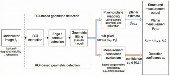
To this end, we construct an underwater visual perception model whose output comprises two components: an in-plane alignment error estimate on the core-plate surface and a detection confidence score quantifying the reliability of that estimate. The overall pipeline is illustrated in Figure 5.
Figure 5.
An illustration of the pin-hole ROI and the geometric detection pipeline.
3.1.1. Underwater Camera Calibration and the Pixel-to-Plane Measurement Model
Based on the coordinate relationships defined in Section 2, a planar calibration procedure is employed to estimate the camera intrinsic matrix and distortion parameters , thereby establishing the projection mapping from the core-plate plane to the image plane. Given the extrinsic transform of the camera with respect to the core-plate frame , the expected pixel location of the i-th hole design center can be expressed as
where denotes the rigid transform from the core-plate frame to the camera frame.
When the camera field of view is relatively small and the end-effector pose is approximately perpendicular to the core-plate plane, the relationship between the pixel deviation of the detected hole center and the actual in-plane alignment error can be approximated locally by a linear model:
where is the pixel-to-plane measurement Jacobian, denotes the pixel deviation relative to the expected location, and n is an equivalent error term induced by higher-order nonlinearities and imaging noise.
3.1.2. ROI-Based Hole Detection and Circle Fitting
Since the guide-tube opening-pin geometry is fixed and the cognition layer can provide a relatively accurate nominal hole position, we adopt a geometry-based detection strategy using a local region of interest (ROI). For each target hole, a fixed-size ROI is cropped around its expected pixel location, thereby reducing background interference and lowering computational cost.
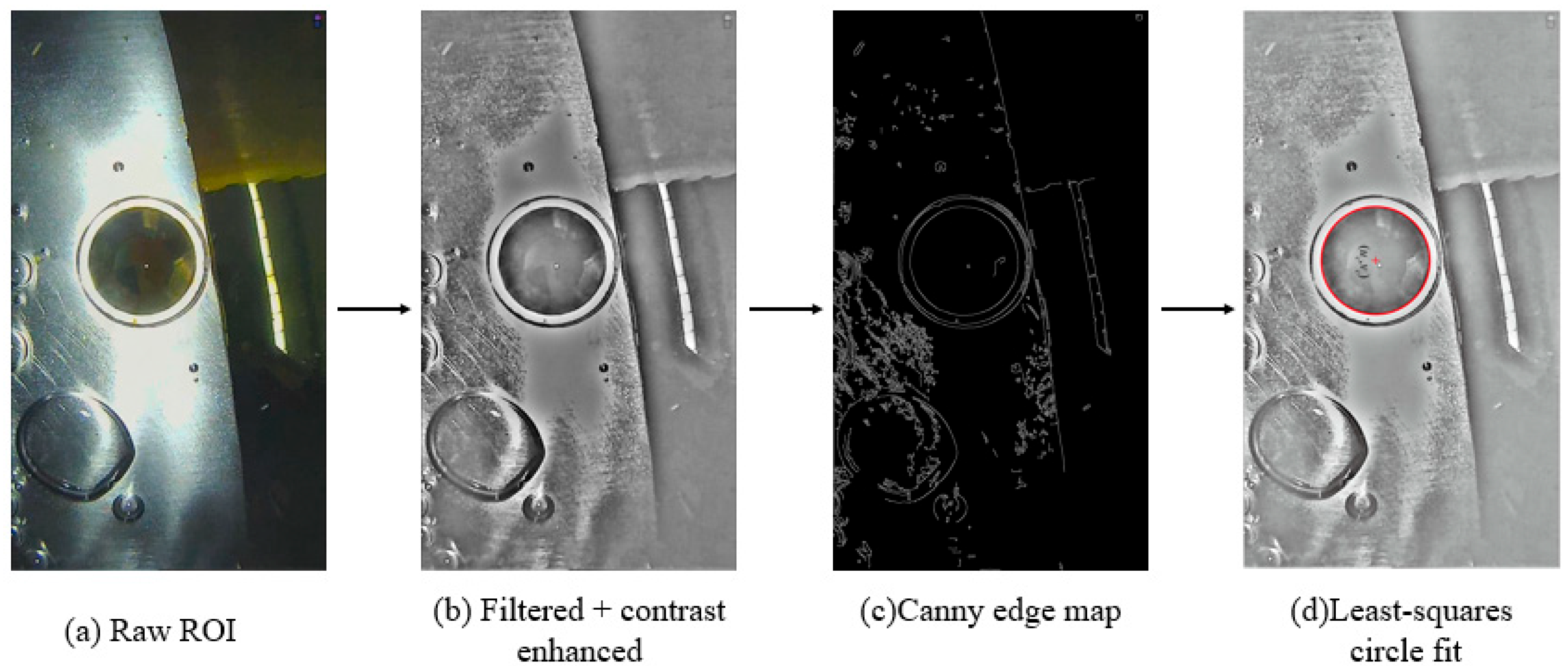
Within the ROI, underwater noise is suppressed via appropriate filtering and contrast enhancement. Edge detection is then applied to obtain candidate boundary points of the hole, followed by a constrained least-squares circle fitting under a predefined radius range. The fitted circle center serves as a subpixel estimate of the pin-hole center; its deviation from the expected pixel location is subsequently mapped into an in-plane alignment error estimate .
This procedure maintains computational efficiency while fully exploiting the geometric prior of the hole structure, resulting in detection outputs that are both interpretable and stable.
3.1.3. Detection Confidence Modeling and Perception Layer Output
To enable the execution layer to distinguish among observation qualities and avoid large control actions using low-quality images [26,27], we map detection-quality indicators to a unified confidence score. Let denote the circle-fitting residual at frame k, and let denote the circularity metric of the detected hole region. We first linearly normalize both indicators and clip them to [0, 1]:
where denotes saturation. We then define the single-frame detection confidence as
This confidence model combines two geometric indicators that closely correlate with detection quality: the circle-fitting residual and the region circularity. The residual measures the consistency between detected edges and an ideal circle model, whereas circularity captures the geometric regularity of the detected region. Together, they describe the quality of observations based on local consistency and global shape regularity, respectively.
By mapping these indicators to [0, 1] and fusing them through a weighted sum, we obtain as a quantitative score of the reliability of the current visual measurement. The control and insertion strategies use to modulate the action magnitude and switch decision modes. The mapping consists of linear normalization with clipping and linear weighted fusion; increases when the residual is small and the circularity is high, indicating a more reliable measurement. The final output of the perception layer is
Here, is the estimated in-plane alignment error on the core-plate surface, and is the associated detection confidence. This structured output serves as the common input to subsequent geometric cognition-based compensation and constrained visual-servoing control.
3.2. Knowledge Base-Driven Geometric Cognition Compensation
To address the geometric mismatch and systematic coarse-positioning bias induced by long-term operation in the component-pool environment, we introduce a hole-oriented geometric cognition scheme under the core-plate frame. The proposed scheme builds a hole-position knowledge base and leverages closed-loop alignment residuals to (i) perform global translation self-calibration of the stage-to-core-plate relationship and (ii) further model spatially varying local geometric deviations via a planar error field, thereby endowing an otherwise static geometric model with the capability of continuous correction.
3.2.1. Hole-Position Knowledge Base on the Core Plate
Taking each guide-tube opening-pin hole as a basic cognition unit, we maintain a structured knowledge record for every hole in the core-plate frame . This record stores the geometric prior, historical alignment performance, and associated statistics. The knowledge-base entry for the i-th hole is defined as
Here, is the design (nominal) hole coordinate; denotes the current inspection status of the hole; is the empirical mean of the residual in-plane error at the end of previous closed-loop alignment runs; is the sample covariance estimate of these residuals; and records auxiliary information such as the latest timestamp, the number of closed-loop iterations, and anomaly flags.
By indexing i = 1, …, 122, where 122 denotes the total number of guide-tube opening-pin holes considered in this work, the knowledge base corresponds one-to-one with the hole array on the upper core plate. It supports task scheduling and provides a unified data interface for cognition-based compensation, error-field modeling, and statistical analysis, enabling long-term “memory” and reuse of the core plate’s geometric state.
3.2.2. Global Translation Self-Calibration Using Calibration Holes
Under practical assembly conditions, the installation transform between the stage base and the core plate , typically exhibits a non-negligible translational bias. If coarse positioning is performed using the nominal geometric model directly, this bias manifests as a global systematic error across the entire plate and increases the convergence burden of the subsequent closed-loop visual servo [28,29].
To eliminate this global offset, we select a small set of calibration holes distributed over different regions of the core plate. After performing vision-based closed-loop fine alignment for each calibration hole, we obtain an estimate of the planar projection of the probe-tip axis in the core-plate frame:
by comparing this estimate with the corresponding design coordinate , the geometric residual is defined as
It is worth emphasizing that is obtained after the planar closed-loop alignment has essentially converged; therefore, the residual primarily reflects systematic assembly and mechanism geometric errors, rather than random noise from a single-frame visual measurement.
Assuming that the installation error can be approximated as a constant translation over the core-plate plane, the global translation bias can be estimated as the least-squares solution, which reduces to the following mean residual:
Then, the translation term in is updated by , yielding the corrected installation transform. This update is computationally lightweight and can be applied during each overhaul or during the full inspection cycle, thereby removing global systematic offsets across the plate.
3.2.3. Planar Error-Field Modeling and Prior Compensation
Beyond the global translation bias, factors such as core-plate manufacturing/assembly tolerances, stage guideway and transmission errors, and structural compliance may introduce spatially distributed local geometric deviations around different holes. Under similar operating conditions, such deviations typically vary slowly with spatial location and exhibit some repeatability across repeated tasks.
Rather than attributing these deviations to specific sources, we treat them collectively as a static systematic error on the core-plate plane and model them via a planar error field. Specifically, over long-term operation, we accumulate residual in-plane error samples at the end of closed-loop alignment for the i-th hole:
where k denotes the task index for that hole. For notational simplicity, we take the sample mean over k to obtain a representative residual for each hole, forming a discrete set of samples .
Assuming the systematic error varies slowly over the plane, we fit regression models for the X and Y direction errors using a shared second-order polynomial basis , yielding a continuous planar error-field estimate:
The model parameters are solved offline via least squares.
During online operation, when the system prepares to coarse-position to the i-th hole, the cognition layer retrieves (i) the historical mean residual and (ii) the error-field prediction , and fuses them into a prior compensation term:
The coarse-positioning target is then corrected from the nominal design coordinate to
and the corresponding initial joint configuration is computed by inverse kinematics . By compensating for a large portion of predictable geometric error in advance, the proposed cognition layer substantially reduces the adjustment range and the number of iterations required by the subsequent vision-servo closed loop.
3.3. Cognition-Driven Decision Making and Closed-Loop Visual-Servo Localization
After geometric cognition compensation, the coarse-positioning error is substantially reduced. However, under complex underwater imaging conditions, visual measurements remain inevitably affected by noise and reliability fluctuations. If fixed-gain or simple proportional control is still adopted, it becomes difficult to simultaneously satisfy travel and step-size constraints while balancing convergence efficiency and operational safety [30,31,32].
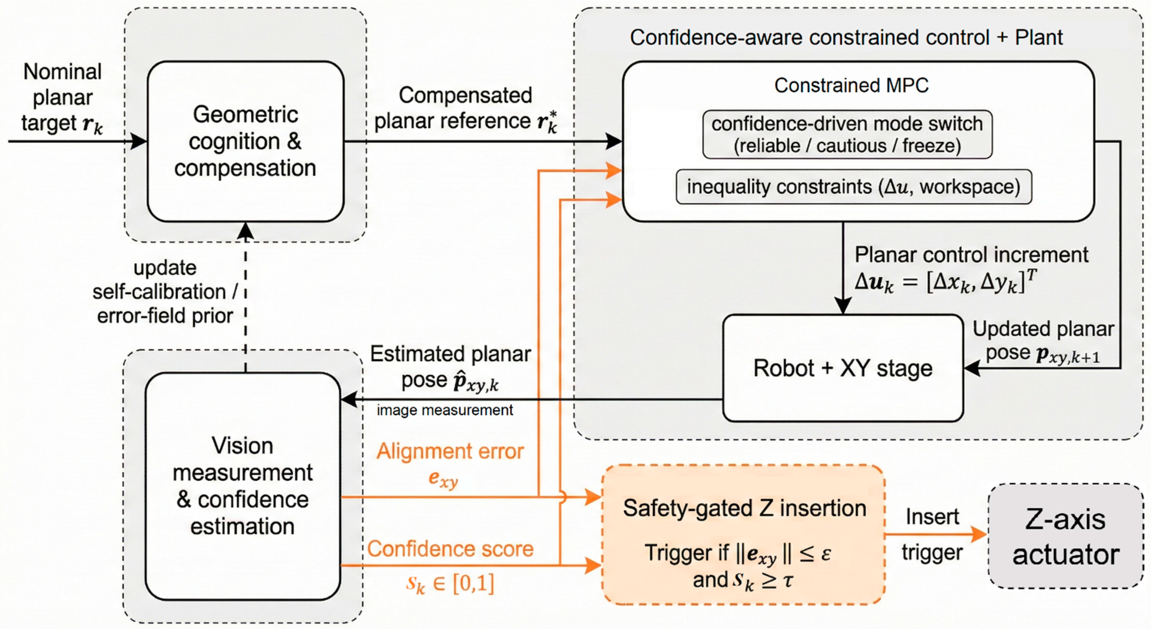
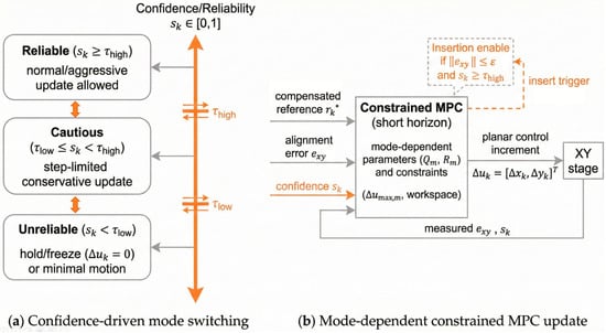
To this end, based on a locally linearized measurement model, we introduce a finite-horizon, constrained model predictive control (MPC) scheme and explicitly incorporate detection confidence as a decision variable within the control framework. Adaptive regulation under uncertain observations is realized through multi-mode switching. The overall closed-loop visual-servoing structure is shown in Figure 6.
Figure 6.
Confidence-aware decision mechanism for robust visual servoing in the presence of uncertain measurements.
3.3.1. Control Problem Formulation
After global self-calibration and planar error-field compensation, the in-plane centering reference for the i-th hole is . At the k-th visual iteration, the perception layer provides an error estimate,
together with the detection confidence . The visual-servo controller takes as input and computes the planar joint increment for this iteration. Under constraints on stage travel, single-step displacement, and safety boundaries, we design a feedback control law:
such that the planar error converges to a preset threshold within a finite number of steps . Moreover, the Z-axis insertion action is permitted only when the planar error has converged and the detection confidence is sufficiently high.
3.3.2. Constrained MPC Design
During planar centering, the stage X/Y axes execute linear motions, and the camera optical axis is approximately perpendicular to the core-plate plane. Based on the pixel-to-plane measurement model, the error dynamics can be first-order-approximated around the current operating point, yielding the discrete linear model:
where is the visual-servo Jacobian, and represents the equivalent disturbance caused by higher-order nonlinearities and measurement noise. In implementation, the visually estimated is used as the state input.
Based on this model, at each iteration, we construct a small-scale MPC problem with a prediction horizon of N = 2. The control command is generated by minimizing a weighted quadratic form of predicted errors and control increments:
where is the predicted planar centering error; is the control increment applied to the X/Y axes of the linear stage at iteration k; and are weighting matrices. The optimization problem in (21) is a constrained quadratic program and is solved at each iteration in a receding-horizon manner to obtain the current control increment, subject to
where represents the travel limits of the stage.
3.3.3. Confidence-Driven Three-State Decision Mechanism
In the underwater component-pool environment, measurement quality varies significantly across operating conditions, and the reliability of single-frame observations can differ markedly. To avoid overly aggressive corrections or erroneous insertion triggers under low-quality observations, the detection confidence is introduced into the decision layer, and a dual-threshold, three-state control mode is constructed.
Let . The system selects one of the following modes based on the current confidence. Reliable mode (): The observation is considered reliable; standard MPC weights are used together with a larger per-step displacement limit to accelerate error convergence. Cautious mode (): The observation is uncertain; the step-size constraint is tightened, and the error weight is increased, enabling only small corrective motions, and insertion is not enabled. Unreliable mode (): The observation is unreliable; no pose update is applied in this iteration, and the abnormal state is logged for subsequent handling.
Different modes adopt different MPC parameter sets , while all are solved within the same optimization framework. This enables smooth switching among “fast convergence—conservative correction—freeze-and-wait.” In practice, an appropriate hysteresis mechanism can be incorporated to prevent frequent switching near the thresholds.
In summary, by integrating constrained MPC with a confidence-driven multi-mode decision logic, the proposed visual-servo framework ensures finite-step convergence of the X/Y planar centering process while explicitly accounting for underwater observation uncertainty and execution safety boundaries, thereby providing a reliable control foundation for automated insertion.
4. Experiments and Results Analysis
4.1. Experimental Platform and Test-Scenario Overview
All experiments in this chapter were conducted on the integrated mobile robot–three-axis linear stage–underwater camera/probe system described above. The system consists of an X–Y–Z linear stage mounted on a mobile robotic platform, a rigidly fixed underwater camera and probe module at the end-effector, and a full-scale upper-core-plate mock-up manufactured to match the real dimensions. This setup enables automated underwater hole perception, planar centering, and insertion operations. The mobile platform is used only for coarse deployment; after coarse positioning, the base is mechanically locked and remains completely stationary during all alignment and insertion trials. Therefore, wheel–ground interaction and wheel-motion control are not addressed by the proposed visual-servoing controller and do not affect the reported alignment accuracy or insertion success metrics. In addition to the main perception camera, a pan–tilt camera is mounted on the platform’s top to record overall motion from a third-person viewpoint; this view is used solely for process documentation and anomaly identification and is not included in accuracy evaluation.
To cover both (i) accuracy analysis under controlled conditions and (ii) system-level validation under near-real operating conditions, two complementary experimental scenarios are designed.
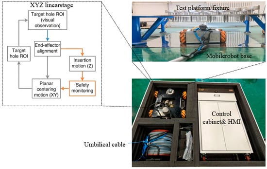
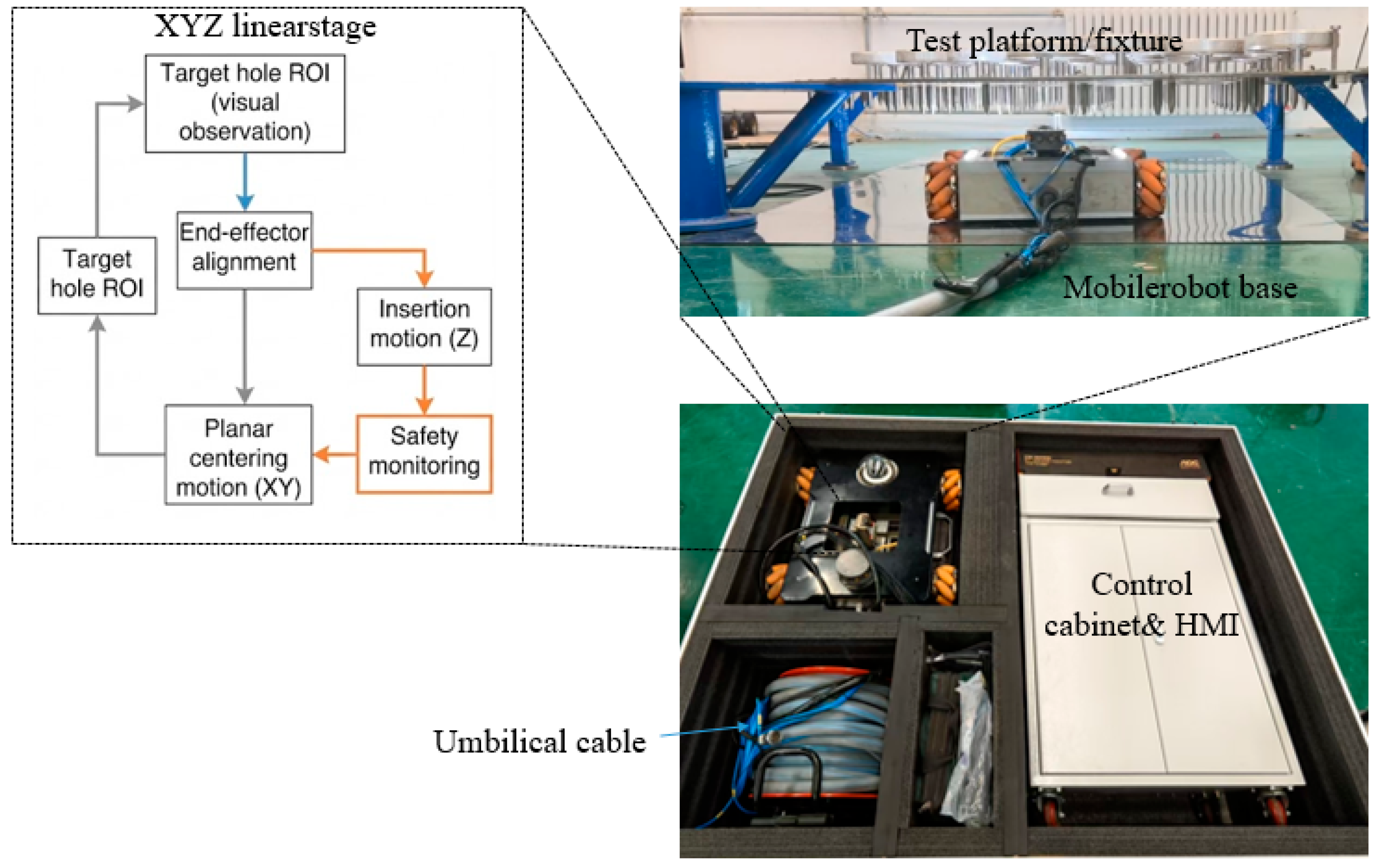
Scenario A—ground experiments and ablation studies. A controllable test environment is established on a ground testbench. The upper-core-plate mock-up is rigidly fixed, and the three-axis stage and camera/probe operate in the air. This scenario enables the use of external high-precision metrology devices and auxiliary calibration artifacts, supporting the validation of the vision measurement model, the evaluation of hole detection and confidence modeling, and ablation experiments for cognition compensation and control strategies. A photo of the Scenario A setup is shown in Figure 7.
Figure 7.
Scenario A: Photograph of the ground experimental platform.
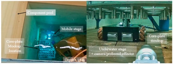
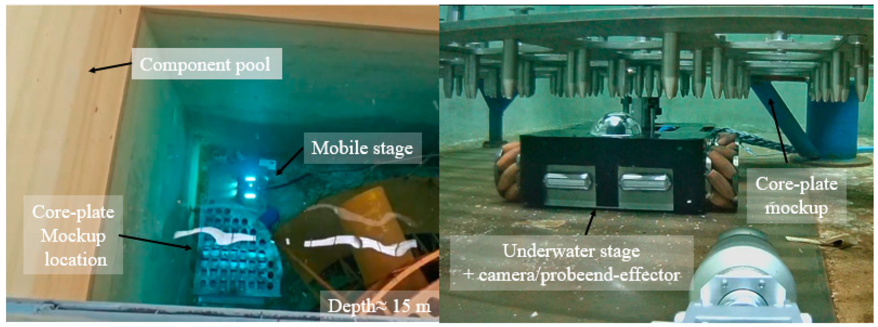
Scenario B (system-level experiments in a deep component pool). A full-scale core-plate mock-up is deployed in a component pool with a water depth of approximately 15 m. The robot operates within a region constrained by support columns, and the three-axis stage, together with the camera/probe module, is fully submerged. This scenario is used to validate system stability and operational safety under realistic underwater illumination, specular reflection, and scattering conditions. The evaluation focuses primarily on the distribution of visual estimation errors and confidence scores, the autonomous insertion success rate, and the presence of abnormal actuator signals or obvious mechanical interference. The installation layout of the deep-water experiment is illustrated in Figure 8. For reproducibility, the key parameters of the underwater vision system and the image acquisition settings used in the experiments are summarized in Table 1.
Figure 8.
Scenario B: A schematic of the deep-water component-pool experimental setup.
Table 1.
The underwater vision system parameters used in experiments.
To provide a unified geometric baseline for subsequent confidence modeling and visual-servo control, the underwater vision measurement model introduced in Section 3.1 is further calibrated, and its accuracy is verified under both scenarios. Specifically, under shallow-water conditions, a checkerboard calibration target parallel to the core-plate plane is placed, keeping the camera installation pose and working distance consistent with real operation. The Zhang [17] planar calibration method is then applied to estimate the camera intrinsic parameters and lens distortion coefficients. In this procedure, multiple checkerboard observations are used to optimize the intrinsic matrix and distortion parameters by minimizing the image reprojection error. In the deep component-pool scenario, the intrinsic parameters are maintained, and only the extrinsic parameters are re-estimated to account for possible installation deviations. The calibration quality is assessed by computing the reprojection error, which serves as an indicator of accuracy for subsequent pixel-to-plane measurement modeling.
Using the available intrinsic and extrinsic parameters, several known holes or marked reference points on the core plate are projected onto the image plane and compared with their measured pixel locations. Using a small-angle local approximation, the local pixel-to-plane Jacobian is estimated, enabling quantification of the planar measurement scale (mm/pixel) and associated error. Table 2 summarizes the reprojection and planar measurement errors under shallow- and deep-water conditions.
Table 2.
Imaging accuracy statistics under shallow- and deep-water conditions.
These results indicate that under both operating conditions, the reprojection error remains at the subpixel level, and the corresponding planar measurement RMS error is well below 1 mm. Moreover, the shallow- and deep-water results are of the same order of magnitude, suggesting that—within the accuracy range of the present experiments—the effect of water depth variation on imaging geometry can be neglected. Therefore, subsequent experiments consistently adopt the underwater calibration intrinsics and the pixel-to-plane Jacobian parameters obtained in this section.
4.2. Pin-Hole Detection Performance and Confidence Analysis
Under the controlled conditions of Scenario A, this section quantitatively evaluates the ROI-based pin-hole detection method and the associated confidence modeling proposed in Section 3.1. The key objective is to analyze the correspondence between the detection confidence and the true in-plane localization error, thereby validating the use of confidence as a modulation variable for subsequent visual-servo control and insertion decisions.
4.2.1. Test Dataset and Evaluation Protocol
To construct a representative dataset, several typical pin holes on the upper-core-plate mock-up are selected. ROI images are collected under varying viewpoint offsets, illumination intensities, and local specular-reflection conditions. For each ROI image, the hole center is annotated manually or via a high-accuracy offline procedure, serving as the reference for planar error evaluation. For each frame, we record the circle-center estimate produced by the perception algorithm, along with its detection confidence.
Based on these data, the pixel-to-plane measurement model in Section 3.1 is used to convert pixel deviations into the in-plane localization error vector on the core-plate plane. The magnitude is adopted as the single-frame detection-accuracy metric.
4.2.2. Detection Examples and Qualitative Observations
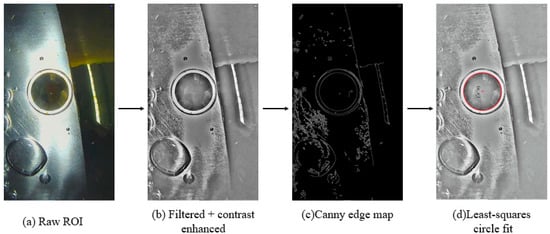
Figure 9 presents representative examples of the detection pipeline applied to ROI images. Starting from the raw ROI, filtering and contrast enhancement are applied, followed by Canny edge extraction to obtain an approximate circular-ring boundary. A least-squares circle fit then yields the hole boundary and a subpixel estimate of the circle center. When image quality is normal, the fitted circle agrees well with the actual hole contour, and the estimated center remains stably near the geometric center of the opening, providing a reliable geometric basis for subsequent planar-error estimation.
Figure 9.
An example of the ROI-based detection pipeline.
When local reflections intensify or edges are corrupted by noise, the fitting residual and the circularity indicator degrade accordingly, and the reported detection confidence decreases. This qualitative phenomenon offers intuitive support for the statistical analysis below.
4.2.3. Statistical Relationship Between Confidence and Planar Error
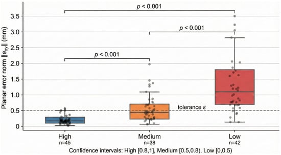
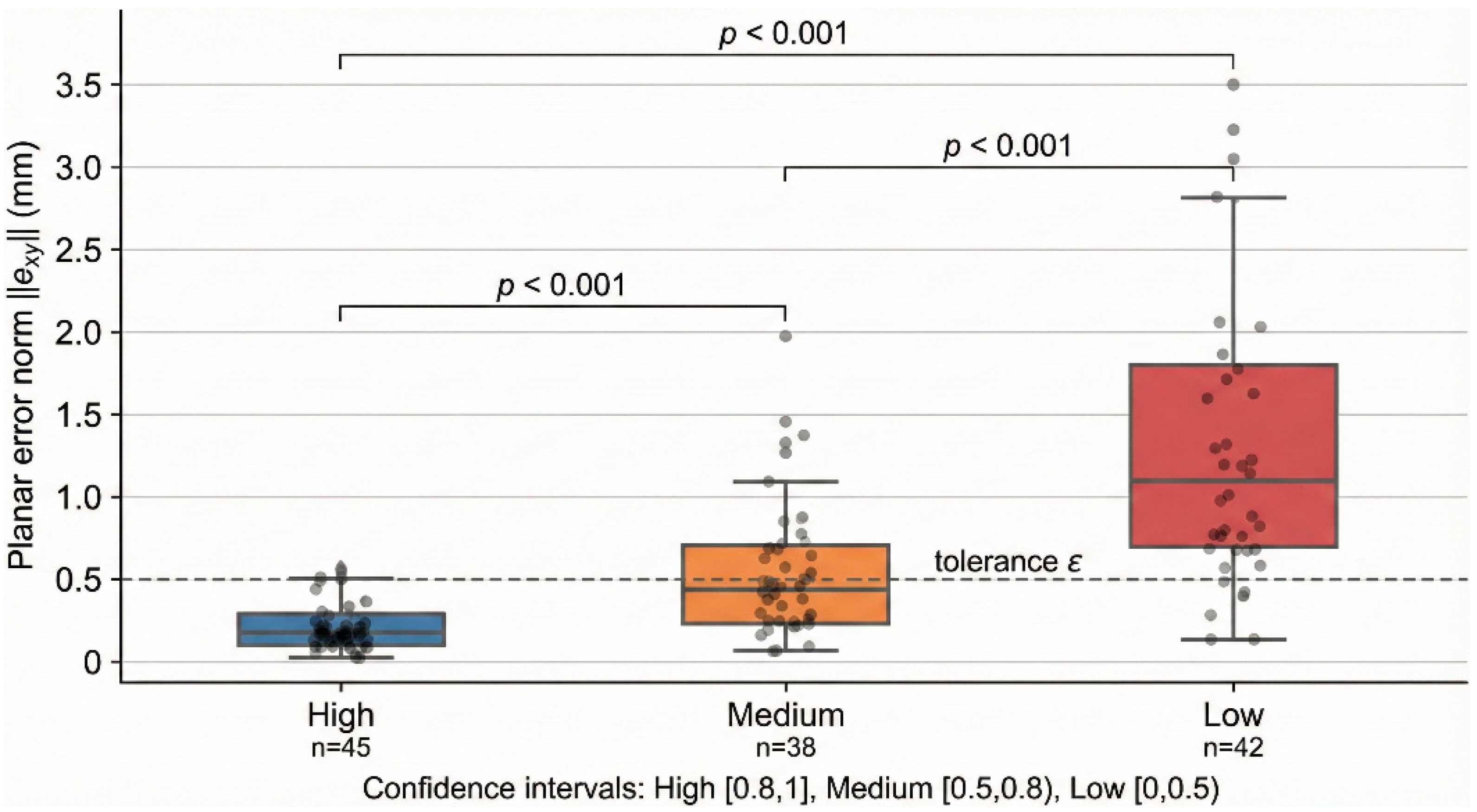
To quantify the discriminative power of confidence, all samples are grouped into three bins according to : high confidence [0.8, 1], medium confidence [0.5, 0.8), and low confidence [0, 0.5). We first applied a Kruskal–Wallis test to assess overall differences among the three confidence bins, followed by post hoc pairwise comparisons on mean ranks with Bonferroni correction in MATLAB 2018a. The p-value from post hoc comparisons on mean ranks follows the Kruskal–Wallis test. For each bin, the distribution of is summarized using boxplots (Figure 10).
Figure 10.
The relationship between confidence and true localization error.
The results show that the high-confidence bin exhibits a markedly lower median error and interquartile range than the medium- and low-confidence bins, with most errors concentrated at the sub-millimeter level. As confidence decreases, the error distribution shifts upward and becomes more dispersed; in the low-confidence bin, a small number of millimeter-level outliers emerge. This trend indicates that the confidence constructed from the circle-fitting residual and circularity effectively reflects the reliability of the current observation.
From a statistical perspective, these results confirm a monotonic correspondence between detection confidence and true planar localization error. This provides experimental support for using confidence as a modulation variable in visual-servo control and insertion decisions: high-confidence observations can justify larger step sizes and faster convergence policies, whereas actively tightening the step limit—or freezing control updates—under low confidence helps to mitigate misadjustment and mechanical interference risks caused by visual degradation.
4.3. Ablation Study of Cognition Compensation and Constrained MPC, and Real-Time Evaluation
This section conducts systematic ablation experiments to clarify how the geometric cognition compensation and cognition-enhanced visual-servo strategy proposed in Section 3 contribute across different control stages. We quantitatively assess their impact on coarse-positioning error, closed-loop convergence efficiency, and insertion success rate, and further report online runtime statistics to verify deployability within practical control cycles.
4.3.1. Ablation Configurations for Geometric Cognition and Control Strategies
To separate the contributions of different modules, four representative control configurations are evaluated in Scenario A, corresponding to increasing levels of geometric compensation and closed-loop control capability:
Config. A (Baseline/IBVS-like): We use only the nominal core-plate-to-stage geometric model. The system computes an initial coarse joint pose via inverse kinematics and then applies a fixed-gain proportional controller to reduce the planar visual error. This configuration includes neither self-calibration nor error-field compensation, and it does not employ constrained MPC or confidence-based decision making.
Config. B (Translation only): Building on Config. A, we introduce global translation self-calibration using closed-loop residuals from a small set of representative holes to remove systematic installation bias between the core plate and the stage base. The remaining control structure stays unchanged (fixed-gain proportional feedback).
Config. C (Translation + error field): On top of Config. B, we further apply planar error-field compensation to account for spatially varying geometric deviations across holes. This compensation improves coarse-position initialization, while the closed-loop controller remains a fixed-gain proportional controller.
Config. D (Proposed): Building on Config. C, we replace proportional control with constrained MPC and introduce a three-state confidence-driven state machine to jointly schedule step size, enforce safety boundaries, and maintain gate insertion triggering.
We select nine representative holes evenly distributed over the core plate. For each configuration, we perform multiple complete centering-and-insertion runs on every hole. For clarity, the ablation study evaluates four configurations with increasing levels of compensation and control capability: A = baseline (no compensation + proportional control); B = translation self-calibration + proportional control; C = translation + planar error-field compensation + proportional control; D = proposed (full compensation + constrained MPC + confidence state machine). Table 3 summarizes the key metrics, including coarse-positioning error, final centering error, convergence iterations, runtime, and insertion success rate.
Table 3.
A performance comparison of four control configurations.
Table 3 shows that geometric cognition compensation consistently reduces the coarse-positioning error before closed-loop refinement. Compared with the baseline, global translation self-calibration decreases the coarse RMS to 1.1 mm, and further adding planar error-field compensation reduces it to 0.9 mm. This improved initialization also translates into better closed-loop outcomes: the final RMS error decreases from 0.8 mm to 0.6 mm and 0.4 mm, while the average runtime drops from 4.2 s to 3.2 s and 2.6 s, respectively.
4.3.2. Impact of Geometric Cognition Compensation on Coarse-Positioning Accuracy
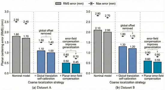
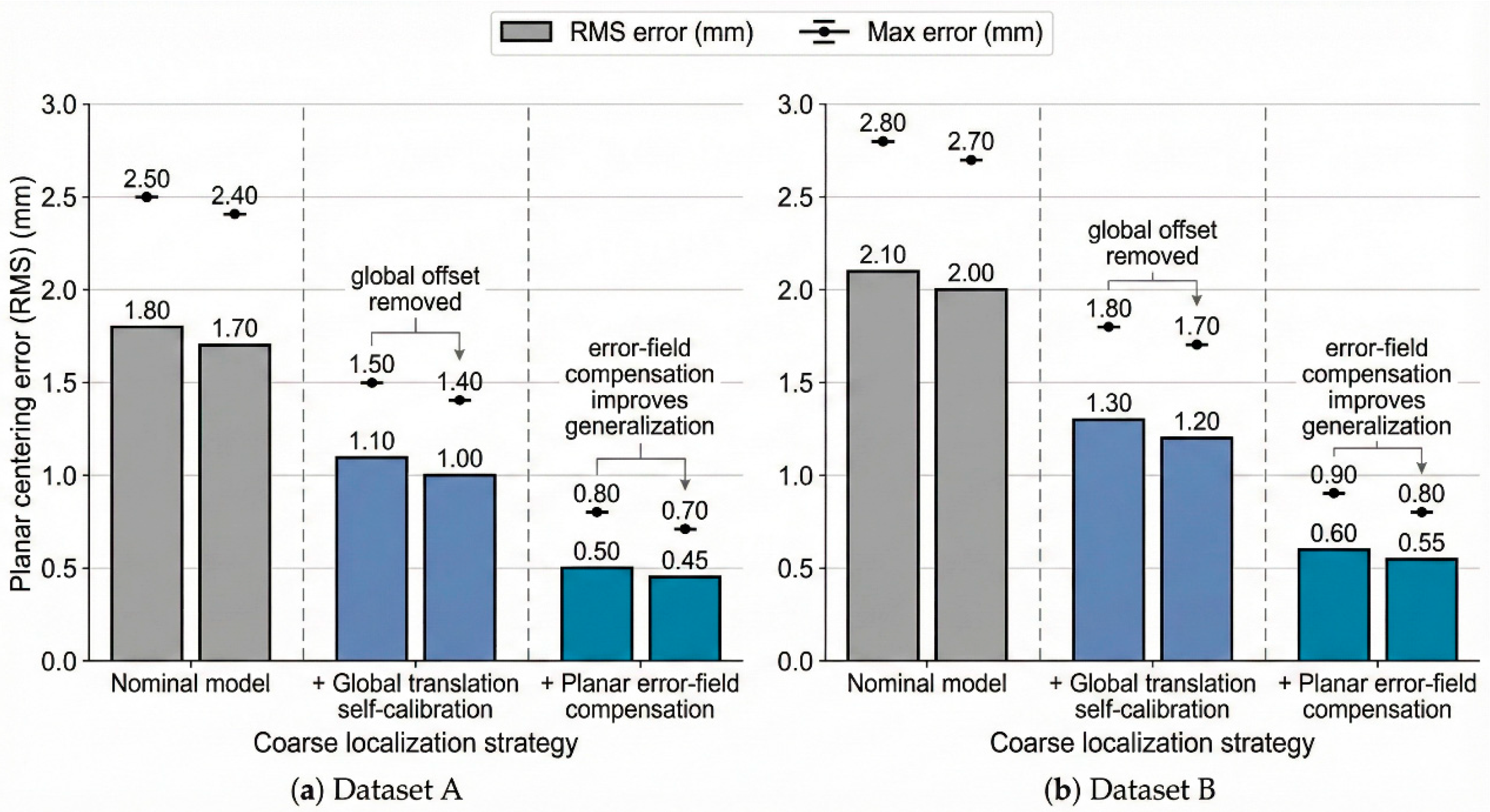
The reported approximately 75% reduction in coarse-positioning error is obtained by comparing the aggregated planar error metric between the baseline setting (without error-field compensation) and the proposed cognition-based compensation across the full set of evaluated trials in this section. Figure 11 reports planar error statistics for different coarse-positioning strategies when the visual closed loop is disabled. Without any compensation, the systematic bias introduced by the nominal geometric model yields millimeter-level coarse-positioning errors. After applying global translation self-calibration, the overall installation offset from assembly is largely eliminated, reducing the coarse-positioning RMS error from the millimeter range to approximately the sub-millimeter level (around 0.5 mm), with a clear reduction in maximum error.
Figure 11.
A bar chart of planar errors at calibration holes under different coarse-positioning strategies.
4.3.3. Effects of Constrained MPC and the State Machine on Closed-Loop Convergence
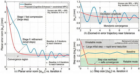
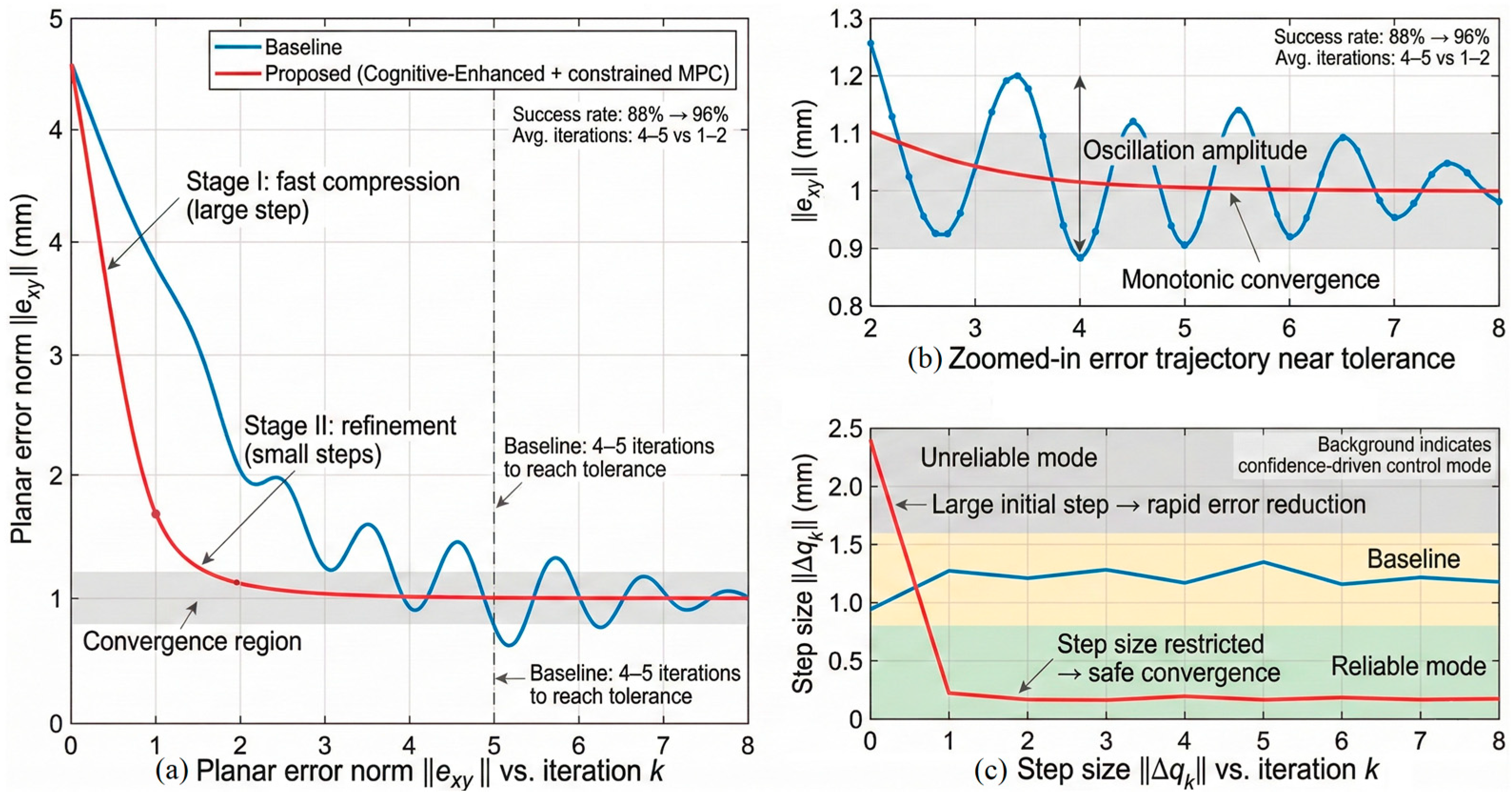
During the closed-loop phase, Figure 12 compares the centering process of the baseline and the full proposed scheme, showing the planar error trajectory for representative holes along with the corresponding joint step-size evolution. Under the baseline configuration, convergence is relatively slow and exhibits oscillations near the threshold, typically requiring multiple iterations to satisfy the insertion condition.
Figure 12.
Planar error trajectory and joint step-size trajectory.
In contrast, after enabling cognition compensation and constrained MPC, representative holes demonstrate a clear “two-stage convergence” behavior: a larger initial control increment rapidly compresses the error toward the threshold, followed by small corrective actions that ensure stable convergence. As summarized in Table 3, the full scheme outperforms the baseline in average iterations, centering time, and auto-insertion success rate, while reducing the dispersion of the post-convergence planar error. In particular, the auto-insertion success rate improves from 88% to 96%.
4.3.4. Online Real-Time Performance Evaluation
To verify the feasibility of the constrained MPC and confidence state machine within practical control cycles, we recorded the per-frame image-processing time , MPC solving time , and total computation time during centering under the full scheme in Scenario A. The statistics are summarized in Table 4.
Table 4.
Online computation-time statistics under the full scheme.
The results indicate that on the current hardware platform, the average computation time of the full scheme is well below the system control period. The results indicate Tc = 50 ms and further claim a sufficient margin, even in the worst case.
4.4. Alignment Accuracy and Nuclear Engineering Tolerance Analysis
In the ground test scenario (Scenario A), to independently verify the final alignment accuracy from the perspective of nuclear-component assembly and operational safety, we introduced a third-party high-precision metrology device to externally measure the alignment results at representative pin holes. The Sharp-49 3D scanner used in this study provides sub-0.05 mm measurement accuracy and serves as an independent geometric reference for the visual-servoing outcomes.
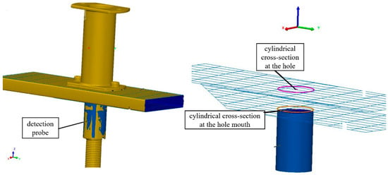
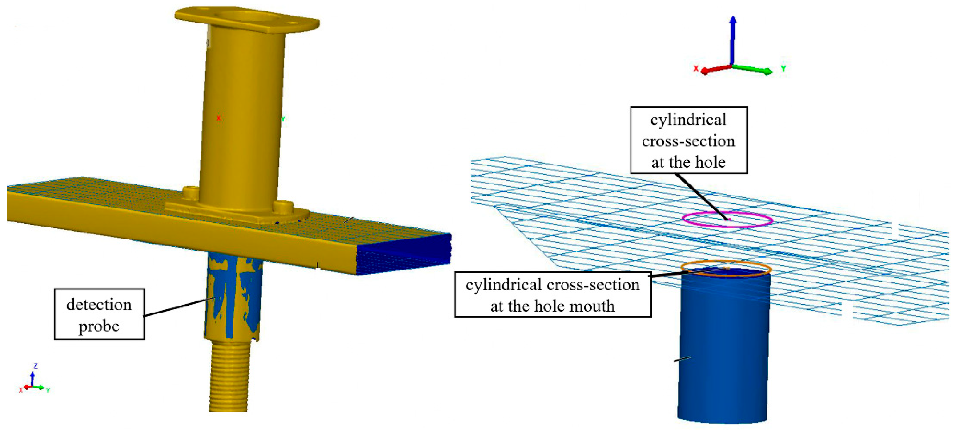
As illustrated in Figure 13, for each test hole, after visual alignment converges and the end-effector pose is held fixed, we perform 3D scans of (i) the cylindrical cross-section at the hole mouth on the upper core plate and (ii) the cross-section at the probe tip. By fitting circular models to both cross-sectional contours, we compute the deviation between their circle centers within the upper-core-plate plane and use this deviation as the planar coaxiality (alignment) error metric.
Figure 13.
A schematic illustration of the Sharp-49 3D scanning procedure.
To improve the transparency of the reported alignment performance, Table 5 summarizes the coaxiality error statistics over representative holes and repeated independent alignment trials under the full cognition compensation plus constrained MPC control scheme.
Table 5.
A summary of alignment error statistics over representative holes and repeated trials.
This experiment provides third-party physical metrology evidence that the framework proposed in Section 3 achieves stable, repeatable sub-millimeter alignment with respect to a real geometric datum, offering direct quantitative support for engineering deployment in high-safety scenarios such as nuclear component pools.
4.5. Deep-Water Validation and Risk-Constrained Assessment
This section conducts system-level experiments in a real deep-water component pool (Scenario B) to comprehensively evaluate the proposed cognition-enhanced visual-servoing and constrained MPC framework, with a focus on applicability under uncontrollable observation quality and the ability to enforce risk constraints.
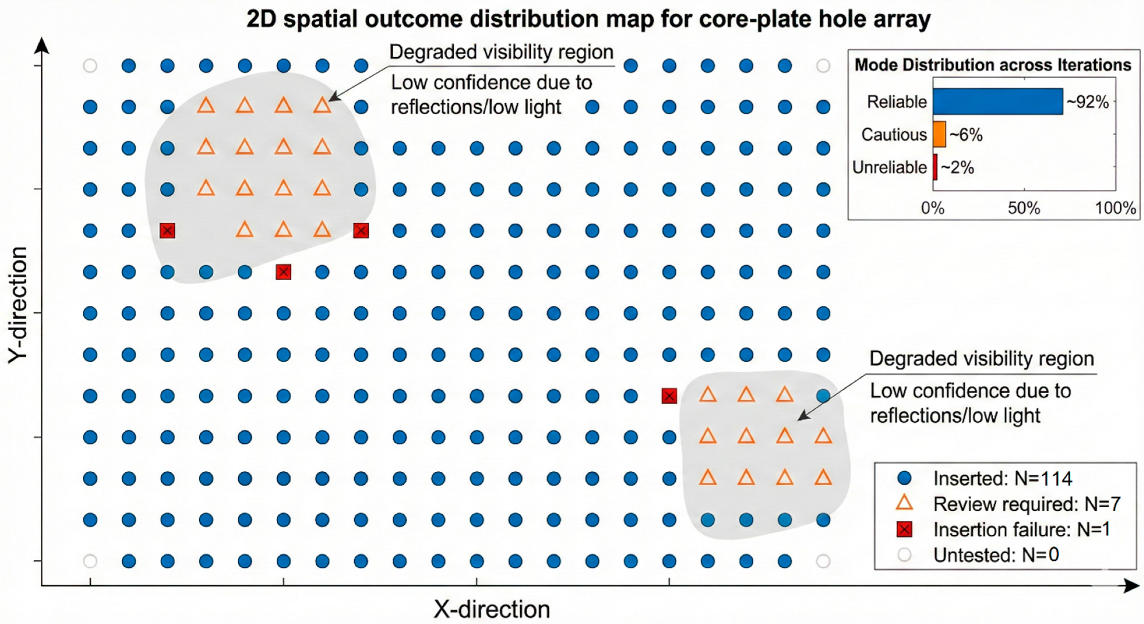
The task covers all guide-tube opening-pin holes on the upper core plate. The hardware configuration and control algorithms are identical to those in Scenario A. Based on visual detection results, control execution, and mechanical feedback signals, the outcome for each hole is categorized into three classes: successful insertion, requires recheck, or insertion failure.
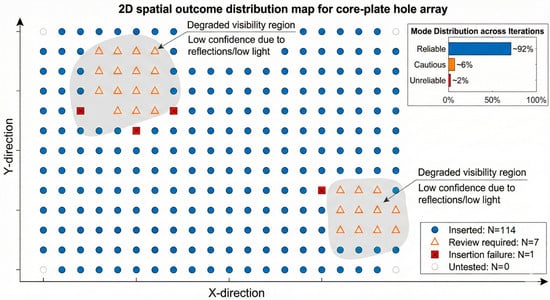
The statistics show that, in the deep-water pool environment, most holes can complete automatic insertion within a single alignment process, and their average alignment time and iteration count are on the same order as those in the ground experiments. The small number of holes labeled “requires recheck” are mainly located in areas with extremely poor illumination or strong specular reflections, where the visual detection confidence remains persistently low; according to the decision logic, the system proactively suppresses insertion actions. Clear insertion failures occur only under artificially constructed extreme interference conditions. The spatial distribution of outcomes over the upper core plate is shown in Figure 14.
Figure 14.
A spatial distribution map of the detection results.
Further statistics over all alignment iterations across the full plate yield the following distribution of operating modes: reliable (high confidence) ≈ 92%, cautious (medium confidence) ≈ 6%, and unreliable (low confidence) ≈ 2%. When the system enters the cautious or unreliable mode, it correspondingly tightens the X/Y step-size constraints or temporarily freezes pose updates, thereby explicitly reducing the risk of erroneous insertion triggered by unreliable observations. These holes are ultimately classified as “requires recheck” and handed off to human operators or specialized handling strategies.
Overall, the results indicate that in a real deep-water component pool, the system maintains efficient automatic alignment and insertion for the vast majority of holes, with good observation conditions, while proactively degrading to conservative strategies in visually degraded regions—confining potential risks to a limited, manageable subset of holes and preventing visual misjudgments from propagating into mechanical safety hazards.
4.6. Discussion
The cognition-enhanced visual-servoing framework proposed in this paper targets high-risk, long-cycle operation scenarios such as nuclear component pools, emphasizing stability and controllable risk under uncertain observations. The experimental results show that geometric cognitive compensation reduces coarse-positioning error by approximately 75%. When combined with constrained MPC, the number of closed-loop alignment iterations is reduced by about 67%, thereby substantially improving operational efficiency. The final alignment error stabilizes at approximately 0.2 mm. Meanwhile, the system can proactively degrade its strategy when observations deteriorate, preventing erroneous decisions from escalating into mechanical safety risks at the system level.
In terms of methodological design, we model long-term geometric bias using global translational self-calibration and a planar error field, motivated by the strong repetitiveness of the upper-core-plate structure and the high consistency of the task. Compared with traditional fixed-gain or heuristic piecewise controllers, constrained MPC provides more predictable convergence behavior under local linearization assumptions.
This study focuses on underwater alignment; the core idea—combining geometric compensation, confidence-aware perception, and constraint-aware optimization—may also serve as a complementary module in related robotic learning and interaction-control pipelines. In particular, it can provide reliability-aware state estimation and constraint-aware motion planning under uncertain observations, which is potentially beneficial for contact-rich tasks that require robust perception and safe control.
The proposed approach also has applicability boundaries. When the structure changes significantly and clear geometric priors no longer exist, the compensation performance will be limited. To mitigate this issue, future work may introduce more adaptive geometric representations and online updating mechanisms to continuously refine the compensation map as the workspace geometry changes. In addition, the current confidence modeling is primarily based on geometric fitting consistency; for extremely degraded imaging conditions, robustness should be further strengthened by incorporating additional perceptual cues. For example, combining multi-feature consistency checks (e.g., edge/shape agreement) and temporal filtering across consecutive frames can improve confidence stability, while learning-based feature representations may further enhance detection robustness under severe scattering, reflections, and low-contrast conditions. These limitations point to meaningful directions for improving adaptability and perception robustness in future work.
5. Conclusions and Future Work
This paper addresses the automated alignment and insertion of guide-tube opening pins on the upper core plate in a component pool during refueling outages. We propose and validate a visual-servoing framework that integrates geometric cognition, confidence-aware perception, and constraint-based optimization control. The framework tightly couples (i) online learning of an error field to compensate for long-term geometric drift, (ii) real-time confidence estimation to characterize observation uncertainty, and (iii) constrained optimal control to ensure operational safety. By explicitly linking perception quality to control decisions, the proposed framework enables stable and predictable centering behavior despite fluctuations in observations during long-term operation.
Experiments demonstrate three major performance improvements:
- (a)
- Accuracy: Through self-calibration and error-field compensation, the systematic coarse-positioning error is reduced by approximately 75%, providing a favorable initial condition for visual servoing.
- (b)
- Efficiency: With constrained MPC, fine centering converges within two steps, reducing the number of iterations by about 67%.
- (c)
- Safety: The confidence-driven decision mechanism proactively isolates potential risks under complex deep-water observation conditions, achieving a success rate above 96%. Moreover, the final alignment accuracy (0.21 mm RMS) is substantially better than the engineering tolerance (±1 mm), leaving a large safety margin.
Although this work is validated on underwater visual alignment, the proposed “cognition–perception–execution” design is not task-specific and can complement learning-based, contact-rich manipulation, such as impedance learning for human-guided robots in unknown environments. In such scenarios, the geometric cognition module can serve as an online bias/parameter compensation layer, the confidence estimation can quantify the reliability of perception/contact-state cues or human guidance and gate policy updates accordingly, and the constraint-aware optimization can act as a safety filter to enforce workspace and interaction limits during execution. Therefore, the framework can enhance robustness and operational safety when observations and contact conditions are uncertain.
Future work will proceed along two directions: (1) execution-level extension—introducing force/torque feedback during the Z-axis insertion stage to develop a compliant insertion strategy that fuses vision and force sensing, thereby handling more complex contact dynamics; (2) perception-level enhancement—exploring advanced feature representations, such as deep learning, to further improve perceptual robustness under extremely poor water quality and challenging lighting conditions. We will also investigate the scalability of the proposed framework to larger workspaces and broader task variants and assess the potential impact of radiation environments on the mobile robot platform and its subsystems for real nuclear applications.
Author Contributions
Conceptualization, J.L.; Methodology, L.S.; Software, J.L. and L.S.; Validation, X.L.; Formal analysis, M.Z.; Investigation, J.L.; Resources, M.Z.; Data curation, J.L. and X.L.; Writing—original draft, J.L.; Writing—review&editing, L.S.; Visualization, L.S.; Supervision, X.L.; Project administration, L.S.; Funding acquisition, M.Z. All authors have read and agreed to the published version of the manuscript.
Funding
This work was supported by the National Natural Science Foundation of China [Grant No. 52275016], the Science and Technology Development Fund Project on Central Government Guiding Local Government [Grant No. 236Z1806G and 226Z1801G], the Science Research Project of the Hebei Education Department [Grant No. CXY2024052 and JZX2023015], and the Natural Science Foundation of Hebei Province [Grant No. F2024202081].
Institutional Review Board Statement
Not applicable.
Informed Consent Statement
Not applicable.
Data Availability Statement
The raw data supporting the conclusions of this article will be made available by the authors on request.
Conflicts of Interest
Author XinBao Li was employed by Jinan FinDreams Battery Co. The remaining authors declare that the research was conducted in the absence of any commercial or financial relationships that could be construed as a potential conflict of interest.
References
- Martón, I.; Sánchez, A.; Carlos, S.; Mullor, R.; Martorell, S. Prognosis of wear-out effect on of safety equipment reliability for nuclear power plants long-term safe operation. Reliab. Eng. Syst. Saf. 2023, 233, 109121. [Google Scholar] [CrossRef] [Scilit]
- Pioro, I.; Duffey, R.B.; Kirillov, P.L.; Pioro, R.; Zvorykin, A.; Machrafi, R. Current status and future developments in nuclear-power industry of the world. J. Nucl. Eng. Radiat. Sci. 2019, 5, 024001. [Google Scholar] [CrossRef] [Scilit]
- Pioro, I.; Duffey, R.; Kirillov, P.L.; Dort-Goltz, N. Current status of reactors deployment and small modular reactors development in the world. J. Nucl. Eng. Radiat. Sci. 2020, 6, 044001. [Google Scholar] [CrossRef] [Scilit]
- Pioro, I.; Duffey, R. Nuclear power as a basis for future electricity generation. J. Nucl. Eng. Radiat. Sci. 2015, 1, 011001. [Google Scholar] [CrossRef] [Scilit]
- Liu, X.; Cheng, W.; Xing, J.; Chen, X.; Li, L.; Guan, Y.; Ding, B.; Nie, Z.; Zhang, R.; Zhi, Y. Predictive maintenance system for high-end equipment in nuclear power plant under limited degradation knowledge. Adv. Eng. Inform. 2024, 61, 102506. [Google Scholar] [CrossRef] [Scilit]
- Huang, X.-Y.; Xia, H.; Yin, W.-Z.; Liu, Y.-K. Research on fault diagnosis and fault location of nuclear power plant equipment. Ann. Nucl. Energy 2024, 205, 110556. [Google Scholar] [CrossRef] [Scilit]
- Lyu, M.; Gong, H.; Chen, Z.; Wang, J.; Zhong, M.; Wang, Z.; Li, Q.; Pan, Z. Deep learning-based dual monitoring system for power forecasting and fault detection in nuclear power applications. Energy AI 2025, 20, 100515. [Google Scholar] [CrossRef] [Scilit]
- Ndum, Z.N.; Tao, J.; Ford, J.; Liu, Y. Automating Monte Carlo simulations in nuclear engineering with domain knowledge-embedded large language model agents. Energy AI 2025, 21, 100555. [Google Scholar] [CrossRef] [Scilit]
- Huang, Y.; Zhuo, Q.; Fu, J.; Liu, A. Research on evaluation method of underwater image quality and performance of underwater structure defect detection model. Eng. Struct. 2024, 306, 117797. [Google Scholar] [CrossRef] [Scilit]
- Kamada, S.; Nishimura, K. Integration of Multiple Sensors into an ROV for Remote Measurement in the Fukushima Daiichi Nuclear Power Station. J. Robot. Mechatron. 2024, 36, 71–78. [Google Scholar] [CrossRef] [Scilit]
- Nauert, F.; Kampmann, P. Inspection and maintenance of industrial infrastructure with autonomous underwater robots. Front. Robot. AI 2023, 10, 1240276. [Google Scholar] [CrossRef] [Scilit]
- Le Ster, M.; Pawłowski, S.; Lutsyk, I.; Kowalczyk, P. Fourier transform-based post-processing drift compensation and calibration method for scanning probe microscopy. Ultramicroscopy 2024, 263, 113984. [Google Scholar] [CrossRef] [Scilit] [PubMed]
- Qiao, X.; Xu, C.; Wang, Y.; Ma, G. SDI: A sparse drift identification approach for force/torque sensor calibration in industrial robots. Neurocomputing 2025, 620, 129292. [Google Scholar] [CrossRef] [Scilit]
- Yuan, X.; Li, W.; Chen, G.; Yin, X.; Li, X.; Liu, J.; Zhao, J.; Zhao, J. Visual and intelligent identification methods for defects in underwater structure using alternating current field measurement technique. IEEE Trans. Ind. Inform. 2021, 18, 3853–3862. [Google Scholar] [CrossRef] [Scilit]
- Zhang, Z. A flexible new technique for camera calibration. IEEE Trans. Pattern Anal. Mach. Intell. 2002, 22, 1330–1334. [Google Scholar] [CrossRef] [Scilit]
- Jiang, S.; Wang, W.; Su, Z.; Wang, S. Automatic detection of surface defects on underwater pile-pier of bridges based on image fusion and deep learning. Struct. Control. Health Monit. 2023, 2023, 8429099. [Google Scholar] [CrossRef] [Scilit]
- Xie, Z.; Zhang, Z.; Chen, J.; Feng, Y.; Pan, X.; Zhou, Z.; He, S. Data-driven unsupervised anomaly detection of manufacturing processes with multi-scale prototype augmentation and multi-sensor data. J. Manuf. Syst. 2024, 77, 26–39. [Google Scholar] [CrossRef] [Scilit]
- Wang, F.; Sun, F.; Zhang, J.; Lin, B.; Li, X. Unscented particle filter for online total image Jacobian matrix estimation in robot visual servoing. IEEE Access 2019, 7, 92020–92029. [Google Scholar] [CrossRef] [Scilit]
- He, J.; Gu, L.; Yang, G.; Feng, Y.; Chen, S.; Fang, Z. A local POE-based self-calibration method using position and distance constraints for collaborative robots. Robot. Comput.-Integr. Manuf. 2024, 86, 102685. [Google Scholar] [CrossRef] [Scilit]
- Trinh, L.; Mercelis, S.; Anwar, A. A comprehensive review of datasets and deep learning techniques for vision in unmanned surface vehicles. Ocean Eng. 2025, 334, 121501. [Google Scholar] [CrossRef] [Scilit]
- Song, W.; Chen, Z.; Jiang, Z.; Deng, J.; Cui, H.; He, X.; Xia, J. Dynamic Feature Fusion Algorithm for Multi-Scale Biological Target Detection in Underwater Environments. Digit. Signal Process. 2025, 170, 105786. [Google Scholar] [CrossRef] [Scilit]
- Sadjoli, N.; Cai, Y.; Seet, G.; Elhadidi, B. PCD reconstruction, object classification and pose estimation for underwater vehicles using orthogonal multibeam forward looking sonar fusion. Ocean Eng. 2023, 288, 116019. [Google Scholar] [CrossRef] [Scilit]
- Kosmopoulos, D. Robust Jacobian matrix estimation for image-based visual servoing. Robot. Comput.-Integr. Manuf. 2011, 27, 82–87. [Google Scholar] [CrossRef] [Scilit]
- Yu, P.; Tan, N.; Mao, M. Position-based visual servo control of dual robotic arms with unknown kinematic models: A cerebellum-inspired approach. IEEE/ASME Trans. Mechatron. 2023, 28, 2328–2339. [Google Scholar] [CrossRef] [Scilit]
- Elmezain, M.; Saoud, L.S.; Sultan, A.; Heshmat, M.; Seneviratne, L.; Hussain, I. Advancing underwater vision: A survey of deep learning models for underwater object recognition and tracking. IEEE Access 2025, 13, 17830–17867. [Google Scholar] [CrossRef] [Scilit]
- Ji, Y.; Wang, J.; Gong, Y.; Zhang, L.; Zhu, Y.; Wang, H.; Zhang, J.; Sakai, T.; Yang, Y. Map: Multimodal uncertainty-aware vision-language pre-training model. In Proceedings of the IEEE/CVF Conference on Computer Vision and Pattern Recognition, Vancouver, BC, Canada, 17–24 June 2023; pp. 23262–23271. [Google Scholar]
- Bao, L.; Zhou, X.; Lu, X.; Sun, Y.; Yin, H.; Hu, Z.; Zhang, J.; Yan, C. Quality-aware selective fusion network for VDT salient object detection. IEEE Trans. Image Process. 2024, 33, 3212–3226. [Google Scholar] [CrossRef] [Scilit] [PubMed]
- Li, B.; Tian, W.; Zhang, C.; Hua, F.; Cui, G.; Li, Y. Positioning error compensation of an industrial robot using neural networks and experimental study. Chin. J. Aeronaut. 2022, 35, 346–360. [Google Scholar] [CrossRef] [Scilit]
- Zeng, X.; Xian, S.; Liu, K.; Yu, Z.; Wu, Z. A method for compensating random errors in MEMS gyroscopes based on interval empirical mode decomposition and ARMA. Meas. Sci. Technol. 2023, 35, 015020. [Google Scholar] [CrossRef] [Scilit]
- Wu, J.; Jin, Z.; Liu, A.; Yu, L.; Yang, F. A survey of learning-based control of robotic visual servoing systems. J. Frankl. Inst. 2022, 359, 556–577. [Google Scholar] [CrossRef] [Scilit]
- Gabrielsen, T.A.L.; Imsland, L.S.; Gros, S.N. Advanced Real-Time Iterations and Short-Horizon Predictor for Fast Nonlinear Model Predictive Control. In 2025 IEEE Conference on Control Technology and Applications (CCTA); IEEE: Piscataway, NJ, USA, 2025. [Google Scholar] [CrossRef] [Scilit]
- Menaldi, J.-L.; Robin, M. Remarks on risk-sensitive control problems. Appl. Math. Optim. 2005, 52, 297–310. [Google Scholar] [CrossRef] [Scilit]

Disclaimer/Publisher’s Note: The statements, opinions and data contained in all publications are solely those of the individual author(s) and contributor(s) and not of MDPI and/or the editor(s). MDPI and/or the editor(s) disclaim responsibility for any injury to people or property resulting from any ideas, methods, instructions or products referred to in the content. |
© 2026 by the authors. Licensee MDPI, Basel, Switzerland. This article is an open access article distributed under the terms and conditions of the Creative Commons Attribution (CC BY) license.