


Abstract
Under-bridge inspection involves complex structural geometries, confined working spaces, and substantial safety risks for manual operation. To address these challenges, this study proposes a hierarchical obstacle-avoidance motion-planning framework for a large road-rail dual-use bridge inspection manipulator. First, a consistent kinematic model is established for an 11-DOF physical actuation system composed of six revolute joints and five prismatic telescopic joints. For inverse kinematics and template matching, the five physical telescopic joints are mapped to two equivalent prismatic variables, whereas collision checking and execution remain in the full physical joint space. Second, an improved bidirectional RRT-Connect planner is developed by integrating goal-biased sampling, multi-candidate expansion, soft low-lift constraints, and combined state and edge validity checking. Third, a pose-library-guided segmented planning strategy is introduced to reuse successful deployment sequences for known targets and to automatically generate intermediate poses for unseen targets. All post-processed trajectories are revalidated for collision and clearance before acceptance. Comparative simulations demonstrate that the proposed framework improves collision-free planning success and suppresses unreasonable high-lift configurations. The framework provides a reproducible planning solution for automated bridge inspection in confined under-bridge environments.
1. Introduction
As bridge infrastructure ages, regular inspection and maintenance are essential for ensuring structural safety and serviceability. Defects such as cracking, corrosion, material spalling, and local structural deterioration are particularly difficult to detect on bridge soffits, narrow structural regions, and other inaccessible areas. Conventional close-range manual inspection is often inefficient, risky, and incomplete. Consequently, bridge inspection is moving toward robotic, automated, and intelligent operation modes [1,2,3]. Recent reviews further show that remote inspection, autonomous systems, and computer-vision-based monitoring have become important directions for structural surface and cable inspection tasks [4,5].
Existing studies on intelligent bridge inspection can be broadly divided into three categories: automated defect inspection systems, robotic inspection platforms, and vision-based monitoring methods. Early research mainly focused on image acquisition and defect identification, whereas recent work has increasingly emphasized the integration of robotic carriers, visual perception, and intelligent damage recognition algorithms. For instance, a robot system for rapid and intelligent bridge damage inspection based on deep-learning algorithms has been developed to improve the automation level of bridge defect inspection [6]. A deep learning-enhanced smart ground robotic system has also been proposed for automated structural damage inspection and mapping, indicating that bridge inspection is gradually extending from simple image collection to integrated perception and damage analysis [7]. In parallel, recent review studies have summarized the application of computer vision methods to general bridge inspection and bridge cable monitoring, further demonstrating the importance of visual sensing for intelligent bridge inspection [4,5].
With the increasing complexity of bridge structures and inspection environments, bridge inspection robotic platforms have gradually evolved from conventional mobile inspection devices to more specialized systems. For steel bridge inspection, a high-mobility inchworm climbing robot has been proposed to improve locomotion and inspection capability in complex steel bridge environments [8]. A hybrid robot for bridge inspection has also been studied, reflecting the trend toward diversified bridge inspection platform configurations [9]. In addition, recent work has explored bridge inspection information modeling based on light detection and ranging, which enriches the sensing means available to bridge inspection systems [10]. These studies indicate that bridge inspection systems are gradually evolving from single-function mobile platforms toward more integrated solutions that combine locomotion, sensing, and inspection data acquisition [1,3].
However, relying only on mobile inspection platforms is still insufficient for complex under-bridge inspection scenarios involving narrow spaces, long-reach deployment, and dense obstacle distributions. For bridge soffits, internal bridge cavities, and regions surrounded by structural components, inspection robots are required not only to reach target regions but also to deploy manipulators safely, adjust end-effector posture flexibly, and complete close-range inspection operations in constrained environments. For such multi-joint and long-reach systems, the planning problem is no longer a simple end-effector positioning problem; instead, it must simultaneously consider overall obstacle avoidance, joint constraints, configuration feasibility, and motion smoothness. Otherwise, collisions, interference, or deployment failure may occur during operation. Recent studies on manipulator motion planning and trajectory generation have shown that robotic systems operating in constrained workspaces must address the coupled challenges of environmental complexity, motion feasibility, and execution quality [11,12,13].
To address obstacle avoidance and configuration control problems of manipulators, recent studies have developed a variety of planning frameworks for industrial, service, and constrained environments. Existing research has extended motion planning frameworks for industrial applications through platforms such as MoveIt [14], and proposed collision avoidance and motion planning methods for industrial manipulators based on heuristic fast marching tree strategies [15]. In addition, obstacle avoidance algorithms based on decision-making force have been developed for robot manipulators [16]. More recently, hybrid sampling assisted BiRRT has been introduced for robotic arm motion planning in complex industrial scenarios [17], improved RRT-based obstacle-avoidance planning has been investigated for dual-arm robots in complex environments [18], and redundancy-based motion planning with task constraints has been studied for robot manipulators [19]. These studies provide important references for manipulator motion planning in cluttered and constrained environments.
Trajectory-level feasibility and intelligent execution have also attracted increasing attention. Chen et al. proposed a time-optimal trajectory planning method based on seventh-order polynomial interpolation, an event-trigger mechanism, and conditional proportional control, showing that actuator velocity and acceleration constraints should be considered together with trajectory efficiency [20]. For dual-arm manipulation, a cooperative control framework combining vision-language models, online reinforcement learning, grasp detection, and compliant trajectory control has been reported to improve task-level autonomy in unstructured environments [21]. In addition, ROS–Docker-based digital-twin frameworks have been developed to support reproducible robot simulation, monitoring, and control deployment [22]. These studies indicate that practical robotic systems require not only geometric path search but also executable trajectories, perception feedback, and deployable software architectures.
Sampling-based motion planning methods have become an important research direction for high-dimensional robotic motion planning because they do not require explicit analytical descriptions of obstacles and are well suited to complex configuration spaces. Recent review work has systematically summarized the development of sampling-based planners in robotics [12]. Among classical methods, task space regions provide a useful framework for pose-constrained manipulation planning [23]; RRT-Connect significantly improves the efficiency of single-query planning through bidirectional tree expansion and greedy connection [24]; and Karaman and Frazzoli established the theoretical basis of asymptotically optimal sampling-based motion planning [25]. Recent variants further improve sampling efficiency, convergence, and obstacle avoidance, including Hybrid-RRT* for autonomous navigation [26], an improved RRT-Connect method for robotic-arm automatic sampling [27], and comparative studies of RRT and BiRRT under cluttered mission environments [28]. Convex segmentation and homotopy-guided optimization also provide useful insight for globally guided trajectory search in obstacle spaces [29].
In addition to RRT-Connect and BiRRT variants, roadmap-based, optimization-based, and learning-assisted planners are relevant to redundant manipulator deployment. PRM and PRM* are effective for roadmap construction in reusable workspaces, and recent PRM-type improvements have shown better efficiency in large obstacle-crowded environments [25,30]. Trajectory-optimization methods such as CHOMP, STOMP, and TrajOpt can generate smooth motions when an initial trajectory and differentiable cost structure are available [31,32,33]; however, benchmarking studies show that their performance depends strongly on scene complexity, initialization, and the planning pipeline [34]. Comparative analyses of RRT, artificial potential field, and CHOMP methods further confirm that collision-free manipulator planning in 3D obstacle environments still involves trade-offs among convergence time, path length, smoothness, and obstacle clearance [35]. Open-source frameworks such as OMPL and MoveIt integrate many of these planners and provide practical collision checking and robot-state interfaces [14,36,37]. Experience-based and self-imitation planning methods can improve planning efficiency by reusing successful states or trajectories, but their transfer to safety-critical large-scale bridge inspection manipulators still requires task-specific validity checking and deployment constraints [38].
Although existing studies have achieved rich results in bridge inspection platforms, manipulator motion planning, sampling-based algorithms, trajectory optimization, and learning-assisted planning, several limitations still remain when these methods are directly applied to bridge inspection manipulators. First, current bridge inspection research focuses mainly on mobile platforms, visual inspection, and damage identification, while relatively limited attention has been paid to the safe deployment process of large manipulators in confined under-bridge spaces. Second, existing manipulator planning studies are mostly oriented to general industrial, mobile-robot, or dual-arm scenarios and lack sufficient consideration of the deployment characteristics of long-reach bridge inspection manipulators. Third, although RRT, RRT*, PRM, CHOMP, STOMP, TrajOpt, OMPL-based planners, and experience-based methods provide important algorithmic foundations, they do not directly encode the staged deployment order, low-lift requirement, telescopic-group coupling, and bridge-specific reuse of successful deployment sequences. Therefore, how to combine bridge inspection task characteristics, manipulator deployment requirements, physical collision verification, and sampling-based global planning remains a problem worthy of further study.
Motivated by the above limitations, this study investigates a motion planning method for bridge inspection manipulators that combines global sampling-based search with guided intermediate poses. First, according to the structural characteristics and operating environment of the bridge inspection manipulator, a motion planning model for constrained under-bridge scenarios is established. Then, a bidirectional sampling-based search strategy is adopted to obtain a collision-free feasible path, while structural prior information is incorporated into the deployment process to improve planning efficiency and execution stability. Finally, simulations and experiments are carried out to verify the effectiveness of the proposed method in the deployment process of the bridge inspection manipulator.
Compared with existing BiRRT, RRT-Connect, MoveIt-based planning, and experience-based manipulation frameworks, the novelty of this work does not lie in a single isolated sampling operator. Instead, it lies in integrating bridge-specific structural priors with verified physical collision checking for a long-reach road-rail bridge inspection manipulator. The main innovations are reflected in the following three aspects:
- 1.
- A bridge-task-oriented bidirectional RRT-Connect planner is constructed for narrow under-bridge deployment. Goal-biased sampling, multi-candidate expansion, soft low-lift constraints on key joints, and combined state and edge validity evaluation are coupled with the physical 11-DOF collision model rather than only with the reduced kinematic model.
- 2.
- A segmented planning method guided by a pose library and joint-sequence priority is proposed for complex target configurations where one-shot direct planning has a low success rate. The method reuses successful bridge deployment experience through template matching and automatically generates intermediate poses for unseen targets, decomposing the high-dimensional coupled deployment process into several lower-coupling local planning subproblems.
- 3.
- A hierarchical closed-loop planning framework of “direct planning–failure fallback–experience update” is constructed. It adaptively switches between direct search and guided segmented planning, revalidates the smoothed path for collision and clearance, and stores verified successful sequences for repetitive inspection tasks.
2. System Design
2.1. Design Requirements
This study designs a road-rail dual-use bridge inspection system equipped with a manipulator for close-range inspection of outer webs and bottom slabs. Its functional design must simultaneously satisfy the requirements of transportation, rapid deployment, inspection coverage, sensing, and safety control.
The inspection system should be capable of road-rail dual-purpose transportation and rapid deployment. Considering that bridge inspection tasks are characterized by scattered operation points and frequent cross-regional transfers, the inspection equipment should be compatible with two types of carrying platforms, namely highway vehicles and railway flatcars, and should enable rapid loading and fixation without modifying the original structure of the carriers, thereby improving the mobility and field application efficiency of the system.
The system should have a large inspection coverage range and strong spatial accessibility. The bottom slab and web areas of high-speed railway bridges are usually far from the bridge deck, and the cross-sectional dimensions of bridges vary significantly with bridge type. Especially for common simply supported box girders, continuous girders, and continuous rigid-frame bridges, the cross-sectional dimensions differ greatly between the mid-span and pier-top regions, requiring the inspection system to adapt to inspection demands under different bridge types and working conditions. Based on the cross-sectional analysis of typical high-speed railway bridges, the horizontal working range of the bridge inspection manipulator should cover common bridge widths and meet the one-time inspection requirements of target areas under the bridge. For a general 32 m double-track simply supported box girder for high-speed railways, the manipulator should be able to cover the entire lower edge of the girder span in a single deployment on either track. For continuous girders and continuous rigid-frame bridges, it should also adapt to special inspection positions with large girder heights at piers. Therefore, the manipulator should not only have a long extension length but also realize rotation, pitching, folding, unfolding, and end-effector pose adjustment through multi-joint coordination to meet the close-up inspection requirements of bridge webs and bottom slab areas. Considering on-site dimensional constraints, the designed horizontal working range of the system should be no less than 17 m, with sufficient vertical downward probing and lateral spanning capabilities.
The system should possess strong environmental adaptability in complex scenarios. High-speed railway bridge inspection environments usually contain catenaries, catenary poles, inspection walkway railings, sound barriers, and other facilities. These auxiliary structures impose significant constraints on the deployment path, working posture, and inspection space of the manipulator. Therefore, the influence of external obstacles should be fully considered in the structural and motion design of the system. The dimensional parameters, joint layout, and telescopic range of the manipulator should be reasonably determined to enable it to cross side railings or sound barriers and complete stable deployment and precise inspection in confined spaces. For typical bridge scenarios, the manipulator should be capable of crossing lateral auxiliary facilities, with a vertical crossing height suitable for meeting an operation requirement of approximately 3 m, and the lateral spanning width of the main arm should satisfy a space access demand of about 4.5 m.
In addition, the system should have multi-sensor collaborative inspection capabilities. Bridge disease inspection not only requires acquiring appearance image information such as cracks, spalling, water seepage, and exposure of steel bars on the bridge surface but also needs to perceive in real-time the relative distance, attitude changes, and motion state between the end detection module and the measured surface. Therefore, the system should integrate a visual inspection unit, a distance measurement sensing unit, and an inertial detection unit, and realize end-effector pose estimation, distance constraints, and detection state monitoring through multi-source information fusion, thereby improving inspection positioning accuracy and operation stability. At the same time, the end effector should have a certain modular expansion capability to support the installation and switching of cameras, laser rangefinders, lighting equipment, and other detection sensors. Combined with bridge inspection requirements, the end of the manipulator should have a load capacity of not less than 30 kg to ensure the stable installation of various detection modules.
Finally, the system should have integrated control and safe operation capabilities. The bridge inspection process involves multiple links such as transportation chassis bearing, manipulator deployment, end sensor acquisition, data transmission, and energy supply, requiring the construction of a unified control architecture to achieve coordinated scheduling among various functional units. At the control level, the system should be able to realize the motion control of each joint of the manipulator, the control of the end detection module, the collection and transmission of sensing information, and the state monitoring of the operation process. At the safety level, mechanisms such as attitude feedback, load monitoring, motion constraints, and fault early warning should be adopted to ensure the safety and reliability of the manipulator during the entire process of deployment, recovery, and inspection. Especially considering the large overall size and large motion range of the bridge inspection manipulator, the system must have good structural stability and anti-overturning capability, and should minimize the impact of end vibration on inspection accuracy. To ensure inspection quality, the swing amplitude of the end effector after reaching the target position should be controlled within a small range, and the shaking in the up, down, left, and right directions should generally not exceed 0.10 m.
In summary, the road-rail dual-use manipulator-based inspection system must support road-rail transportation, rapid deployment, wide-area coverage, high accessibility, reliable perception, controllable motion, and safe close-range inspection of bridge webs and bottom slabs. These requirements provide the basis for the system architecture, manipulator configuration, sensing system, and control architecture developed in the following sections.
2.2. Overall Design
Based on the above requirements, the proposed road-rail dual-use manipulator-based bridge inspection system is mainly composed of five parts: a road-rail dual-purpose chassis, a telescopic arm mechanism, end sensors, a control system, and an energy system. The road-rail dual-purpose chassis undertakes the functions of overall load bearing, transportation adaptation, and on-site support. The telescopic arm mechanism, as the core execution unit, is used to achieve close-range operation in the bridge inspection area. The end sensors are used to obtain images, distance, and attitude information of the bridge surface. The control system is responsible for the unified coordination of vehicle operation, manipulator movement, and the inspection process. The energy system provides continuous power supply for the inspection device.
During system operation, the inspection vehicle is first carried by a highway truck or railway flatcar to the designated bridge inspection area. After platform fixation, the manipulator is gradually extended out of the bridge deck and turned to the bottom of the bridge through the cooperative movement of the rotating base and multi-joint telescopic arm. Then, the end detection device reaches the target area to perform image acquisition, distance measurement, and attitude sensing on the bridge surface. The relevant data are processed by the main control system and transmitted to the host computer or cloud platform to realize the inspection and analysis of the bridge structural state. Thus, a complete operation chain of “transportation deployment–manipulator deployment–end inspection–data return” is formed.
2.3. Manipulator Module Design
The road-rail dual-purpose chassis adopts a modular multi-bearing platform structure, which is mainly composed of a bottom plate, cross beams, and corner fittings at four corners. The corner fittings adopt a standardized interface form and cooperate with twist-lock devices to realize mechanical fixation, enabling the system to quickly switch the carrying mode between highway vehicles and railway flatcars. This structure improves the transportation versatility and deployment flexibility of the inspection equipment, providing a stable platform foundation for on-site bridge inspection.
The telescopic arm mechanism is composed of a base, a main arm, multi-degree-of-freedom joints, Telescopic Arm 1, Telescopic Arm 2, and an end detection unit. The main arm is connected to the rotating base through a pitching mechanism to realize the overall direction adjustment of the manipulator. Both stages of telescopic arms adopt a multi-section telescopic structure. The end joint is used to complete pose adjustment in narrow spaces. Through the coordinated action of base rotation, joint rotation, and telescopic arm extension, the manipulator can cover the outer and bottom inspection areas of the bridge, meeting the requirements of large-range and multi-pose close-range bridge inspection. The overall structure and deployment form of the detection system are illustrated in Figure 1.
Figure 1.
Schematic diagram of the detection system.
The end detection system adopts a multi-sensor fusion scheme, mainly including a high-resolution industrial camera, an ultrasonic ranging sensor, and an inertial measurement unit. The industrial camera is used to collect image information of the bridge surface, supporting the detection of typical defects such as cracks, spalling, and corrosion. The ultrasonic ranging sensor is used to measure the relative distance between the end effector and the bridge surface, enabling detection distance adjustment and anti-collision control. The inertial measurement unit is used to obtain end-effector attitude and motion state information, providing support for image stabilization and pose estimation. After fusion processing, multi-source sensing information can provide a basis for target positioning and safe operation during bridge inspection.
The control system consists of a main control unit, an attitude detection module, a visual recognition module, a human–computer interaction terminal, and a remote communication module. The main control unit is responsible for the coordinated control among the chassis, manipulator, and detection device. The attitude detection module and visual recognition module complete state monitoring and detection information processing, respectively. The human–computer interaction terminal is used for parameter configuration and task management, and the remote communication module is used for real-time transmission of detection data and equipment status. This control architecture ensures the coordinated implementation of inspection vehicle travel, manipulator deployment, and detection tasks.
The energy system is composed of a power battery pack, a hydraulic power unit, and an energy management module, which is mainly responsible for the energy supply for vehicle drive, manipulator hydraulic actuation, and end detection devices. Through the electro-hydraulic cooperative energy supply mode, the system can meet the continuous operation requirements under various working conditions such as platform bearing, arm deployment, and sensor detection during bridge inspection.
3. Kinematic Model
The manipulator kinematic model provides the foundation for motion planning, obstacle-avoidance control, and trajectory tracking. This section first analyzes the manipulator configuration and degrees of freedom, and then establishes the forward and inverse kinematic models required for subsequent planning and control design.
To satisfy the requirements of large operating range, confined space, and variable inspection postures in under-bridge scenarios, a multi-section telescopic manipulator is designed. The manipulator adopts a four-section serial main-arm configuration composed of a fixed section and a telescopic section.
The fixed section is mainly used for basic attitude adjustment and overall structural support of the manipulator, including two rigid links. The first arm (Link 1) is connected at one end to the rotating mechanism of the inspection vehicle base, realizing the overall direction adjustment of the manipulator. The second arm (Link 2) is connected to the first arm through a revolute joint, completing the preliminary attitude adjustment of the manipulator and serving as an intermediate transition structure connecting the fixed section and the telescopic section.
The telescopic section is mainly used to expand the operating range of the manipulator and achieve large-range inspection at the bottom of the bridge. This part is composed of two-section and three-section nested telescopic arms, respectively. The third arm (Link 3) is the first telescopic section (two-section); the fourth arm (Link 4) is the second telescopic section (three-section).
The manipulator is integrally mounted on the rotating base of the inspection vehicle platform. Through the coordinated motion of each joint and the extension and retraction of the telescopic arms, the end effector of the manipulator can achieve a large-range motion in the under-bridge space, thereby completing the inspection of the bridge bottom slab and the area near the pier.
3.1. Forward Kinematics
The number of degrees of freedom of the manipulator directly affects its motion flexibility and obstacle-avoidance capability in complex environments. Combined with the requirements of bridge inspection operations, the manipulator designed in this study adopts a redundant physical configuration with six revolute joints and five prismatic telescopic joints. The physical actuated joint vector is defined as
Among these variables, the revolute joints adjust the relative posture between manipulator links, including the base rotation joint, pitch joints, intermediate structural joints, and end posture adjustment joints. The base rotation joint changes the overall orientation of the manipulator, allowing it to extend from the bridge deck toward the outer side of the bridge. The pitch and intermediate joints adjust the spatial posture of the manipulator in vertical and horizontal directions, enabling the end effector to reach the under-bridge operation area. The distal revolute joints finely adjust the posture of the detection end effector so that the inspection sensors face the bridge surface at an appropriate angle.
The five prismatic variables are physical telescopic joints. Joints 5 and 6 belong to the first nested telescopic arm, and Joints 9, 10, and 11 belong to the second nested telescopic arm. In later inverse-kinematics and template-matching calculations, these five physical prismatic joints are represented by two equivalent telescopic variables because the joints within each telescopic group are collinear. This equivalent representation is used only for numerical conditioning and high-level guidance; collision checking, stroke-limit checking, and trajectory execution are always performed after mapping back to the physical 11-DOF vector .
In summary, the total number of physical actuated degrees of freedom of the manipulator system is .
In bridge inspection tasks, the pose of the end effector in 3D space is usually described by six degrees of freedom, including three position freedoms (along the X, Y, and Z axes) and three attitude freedoms (rotations about the X, Y, and Z axes). Therefore, the redundancy of the manipulator system is .
Thus, the manipulator belongs to a redundant manipulator system with five physical redundant degrees of freedom. The existence of redundant degrees of freedom enables the manipulator to realize obstacle-avoidance motion by adjusting the intermediate joint posture while completing the end-effector detection task, thereby improving the motion flexibility of the manipulator in the complex structural environment of bridges. In addition, redundant degrees of freedom can also be used for posture optimization and avoiding singular configurations, providing an important foundation for the design of subsequent obstacle-avoidance motion planning algorithms.
The transformation relationship between two adjacent link coordinate systems is described by the standard Denavit–Hartenberg homogeneous transformation matrix , which is a matrix including translation and rotation transformations. Its general expression is:
where i is the link number and represents the homogeneous transformation matrix of the ith link coordinate system with respect to the th link coordinate system. The symbols , , , and are exactly the parameters listed in Table 1. According to the above D-H parameter table, the homogeneous transformation matrices , between adjacent links are derived sequentially, where is the transformation matrix of the end-effector coordinate system with respect to the Link 10 coordinate system .
Table 1.
DH Parameters of the Manipulator.
The homogeneous transformation matrix of the end-effector coordinate system of the manipulator with respect to the base coordinate system is the product of the homogeneous transformation matrices of adjacent links, namely:
By substituting the D-H parameters of each link into the expression of the homogeneous transformation matrix, the specific form of can be obtained after expansion:
Among them, the upper-left matrix is the attitude matrix of the end effector, which describes the posture of the end effector relative to the base coordinate system. The lower-right vector is the position vector of the origin of the end effector relative to the origin of the base coordinate system, which describes the position of the end effector.
By substituting the joint angles , , , , , and the telescopic joint lengths , , , , into the above matrix, the position and attitude of the end effector can be obtained, and the forward kinematics solution is completed. The forward kinematics equation establishes the mapping relationship between the manipulator inputs (joint angles, telescopic lengths) and outputs (end effector pose), which is the foundation for subsequent inverse kinematics solution, motion planning, and obstacle-avoidance control.
3.2. Inverse Kinematics Modeling Based on Equivalent Dimension Reduction and Jacobian Pseudoinverse
Since this system is a highly redundant manipulator with six revolute joints and five physical prismatic joints, it is difficult to obtain a closed-form solution using the analytical method directly. Meanwhile, when the motion directions of multiple prismatic pairs are collinear, the corresponding column vectors in the Jacobian matrix may become linearly dependent or nearly linearly dependent, which will lead to rank deficiency or an increased condition number of the matrix, affecting the stability of the pseudoinverse solution. Therefore, this study adopts a hybrid inverse kinematics solution method based on equivalent dimension reduction and Jacobian pseudoinverse.
According to the configuration and D-H parameters of the manipulator, the motion directions of the two prismatic joints (Joint 5 and Joint 6) contained in the third arm are collinear, and the motion directions of the three prismatic joints (Joint 9, Joint 10, and Joint 11) contained in the fourth arm are also collinear. To alleviate the column correlation problem caused by collinear prismatic pairs and improve the numerical inversion stability of the Jacobian matrix, equivalent dimension reduction is performed on the co-directional telescopic joints in this paper.
We define the equivalent prismatic joint variables and , which represent the total displacements of the two groups of collinear telescopic mechanisms, respectively:
After equivalent substitution, the original 11-DOF physical manipulator is mathematically represented as an eight-variable equivalent model for differential inverse kinematics (six revolute variables and two equivalent prismatic variables). We define the equivalent joint variable vector after dimension reduction as:
This equivalent model eliminates internally linearly dependent Jacobian columns while maintaining the reachable end-effector workspace. It should be emphasized that the reduction does not remove physical joints from the robot model. Each equivalent prismatic solution is mapped back to the corresponding physical telescopic joints before stroke checking, collision checking, trajectory smoothing, and execution. Therefore, the collision geometry of each telescopic section and the physical feasibility of every generated configuration are preserved.
In the equivalent joint space, the differential relationship between the velocity of the end effector in the task space and the equivalent joint velocity can be expressed as:
where is the Jacobian matrix of the equivalent manipulator system. Since the equivalent system still has two redundant degrees of freedom (), the above equation has infinitely many solutions.
The Jacobian matrix is the core tensor that establishes the mapping relationship between joint space velocities and Cartesian space end-effector velocities. For the reduced eight-degree-of-freedom equivalent manipulator system, the operational space velocity consists of the linear velocity and angular velocity of the end effector. The corresponding equivalent Jacobian matrix can be partitioned into the linear velocity Jacobian matrix and the angular velocity Jacobian matrix :
According to the vector product of the manipulator link motion transmission, the ith column component of the Jacobian matrix, , is completely determined by the type of motion pair of the ith equivalent joint. Combined with the homogeneous transformation matrix derived in the forward kinematics analysis, the specific construction rules for each column vector are as follows:
For revolute joints (such as in the equivalent vector): A revolute joint not only changes the attitude of the end effector but also generates linear velocity through the lever effect. Its Jacobian column vector is constructed as:
where is the direction vector of the Z-axis of the th link coordinate system in the base coordinate system, representing the direction of the rotation axis; is the position vector of the origin of the th link coordinate system in the base coordinate system; is the absolute position vector of the manipulator end effector in the base coordinate system; the symbol × denotes the cross product of three-dimensional vectors.
For prismatic joints (such as the telescopic variables in the equivalent vector): The pure translational motion of a prismatic joint only changes the spatial position of the end effector, not its spatial attitude. Therefore, the angular velocity Jacobian component is zero, and its column vector is constructed as:
where is the three-dimensional zero vector, indicating that the telescopic motion does not contribute to the end-effector angular velocity; denotes the projection of the translation direction of the equivalent prismatic joint in the base coordinate system.
All geometric parameters and required in the above construction process can be directly extracted from the homogeneous transformation matrix of each link derived in the forward kinematics analysis. Specifically, is the third column of the rotation matrix, and is the translation vector in the fourth column of the first three rows of the matrix. This analytical construction method effectively avoids direct differentiation of the complex forward kinematics equations, ensuring the real-time calculation accuracy of the Jacobian matrix of the highly redundant manipulator in the complex bridge inspection environment.
To achieve complex obstacle avoidance while ensuring end-effector trajectory tracking, this study adopts the Moore–Penrose pseudoinverse combined with null-space projection for solving:
where is the pseudoinverse of the Jacobian matrix; I is the identity matrix; is the null-space projection matrix. The equation consists of two parts: the first term is the minimum-norm solution that satisfies the main task of the end effector (trajectory tracking); the second term is the homogeneous solution, which utilizes the null space of the Jacobian matrix to drive the manipulator to perform self-motion by designing an arbitrarily given joint velocity vector without changing the pose of the end effector. The main function of the inverse kinematics model in this section is to establish the mapping relationship between the end-effector pose and joint variables, and to provide theoretical support for subsequent joint-space motion planning, target configuration representation, and motion constraint analysis.
After obtaining the target displacement or velocity of the equivalent prismatic joints through differential inverse kinematics, it needs to be reversely mapped to the actual five physical telescopic joints. To avoid uneven structural stress or reaching the physical dead zone caused by overextension of a single nested joint, this study adopts a stroke-ratio allocation strategy based on the maximum physical stroke of each nested joint.
We let the maximum allowable stroke of the actual prismatic joint i be . Then, for the set S of collinear prismatic joints in the same direction (e.g., or ), the commanded joint velocity (or position increment) is assigned according to the following weight:
where is the corresponding equivalent joint velocity solved by the pseudoinverse algorithm. For position-level mapping, the same ratio is used, namely , followed by the individual stroke-limit check . This allocation strategy ensures synchronization and load balancing of multi-node telescopic motion during operation. More importantly for planning, every equivalent state is lifted back to before the MoveIt collision model is queried, so the physical lengths and positions of all telescopic sections are retained.
In summary, this paper completes the configuration analysis, forward kinematics modeling, and inverse kinematics modeling of the bridge inspection manipulator, providing the mechanical structure constraints, kinematic mapping relationships, and target configuration representation basis for the subsequent construction of the joint-space motion planning method.
3.3. Workspace Analysis
Based on the motion ranges of each joint of the manipulator, this study adopts the Monte Carlo random sampling method to discretely sample the joint space and combines the forward kinematics model to calculate the position distribution of the end effector in the base coordinate system. The joint motion ranges used for workspace sampling are listed in Table 2. According to the task requirements, the motion intervals of each joint are re-constrained, in which the revolute joints are limited by angular ranges, the prismatic joints are limited by telescopic strokes, and some joints are kept fixed and do not participate in sampling. On this basis, the workspace point cloud of the manipulator end effector is obtained, as shown in Figure 2. It can be seen from the figure that the manipulator can form a large spatial coverage under the current joint constraints, which can well meet the spatial requirements for lateral, downward, and long-distance extension operations during bridge inspection.
Table 2.
Joint motion ranges of the bridge inspection manipulator.
Figure 2.
Manipulator workspace point cloud.
4. Obstacle Avoidance Planning Algorithm
The motion planning of the bridge inspection manipulator in the confined space beneath bridges requires not only collision-free movement from the initial configuration to the target configuration but also compliance with inspection operation requirements, including end-effector observation posture, inspection distance, overall low-lifting deployment, and path executability. Unlike the point-to-point obstacle avoidance tasks of conventional industrial manipulators, the manipulator used for bridge inspection features a slender configuration, multiple segments, a prominent deployment process, and complex distribution of environmental obstacles.
When conventional RRT-Connect is directly applied to joint-space planning, it often fails to generate a feasible path in the constrained under-bridge environment. Although the improved RRT-Connect strategy used in this study can solve some planning tasks, it may still produce conspicuous and unreasonable high-lift configurations that are unfavorable for safe deployment beneath bridge decks. Moreover, imposing strict angular constraints on key joints to suppress over-lifting compresses the feasible search space and can lead to iteration failure. To resolve this contradiction, this study introduces a guided deployment-planning method. By combining intermediate-pose guidance with segmented planning, the proposed method limits excessive lifting while improving deployment-planning success.
We let the physical joint space of the manipulator be , and any executable manipulator configuration is defined as . Given the initial configuration and the desired end-effector pose corresponding to the target inspection task, the target configuration is first solved by the equivalent inverse-kinematics model and then lifted to the physical joint vector using the telescopic allocation rule in Section 3.2. Subsequently, a continuous collision-free path from the initial configuration to the target configuration is searched within the feasible physical configuration space under the constraints of joint limits, collision avoidance, and task executability.
To address the high failure rate of direct planning, unreasonable one-step deployment, and limited reuse of empirical data in repetitive bridge inspection tasks, this study proposes a hierarchical motion-planning method organized as “direct planning–guided fallback–experience updating”. First, the desired inspection pose of the end effector is generated from the target bridge region, bridge-surface normal, and safe inspection distance. The equivalent dimension-reduced inverse-kinematics model established in Section 3 is then used to solve the target joint configuration, which is mapped back to the physical 11-DOF vector. Second, the improved bidirectional RRT-Connect planner is used for single-segment direct planning in the physical joint space. If direct planning fails or exceeds the allowed search cost, pose-library matching and automatic intermediate-pose generation are introduced to decompose the highly coupled deployment process into locally decoupled subplanning problems. Finally, automatically generated and verified deployment sequences are stored in an experience database, forming a closed-loop updating mechanism for repetitive bridge inspection scenarios.
4.1. Joint Space Obstacle Avoidance Planning Based on Improved Bidirectional RRT-Connect
In bridge inspection tasks, the end inspection point is not only determined by the position of the area to be measured on the bridge surface but also closely related to the inspection distance and observation direction. We let be the target point on the bridge surface, its local normal vector, and the safe inspection distance. The positional component of the end-effector inspection pose is expressed as .
Meanwhile, to ensure the inspection equipment faces the bridge surface at an appropriate angle, the end-effector pose must satisfy the alignment constraint between its main observation axis and the local normal of the bridge. After obtaining the desired end-effector inspection pose, candidate target configurations are solved via the equivalent dimension-reduced kinematic model and then mapped to physical configurations. The bridge inspection manipulator possesses redundant degrees of freedom, and a single end-effector pose generally corresponds to multiple inverse kinematic solutions. After acquiring candidate inverse solutions, this paper further filters them according to lifting preference, joint variation amplitude, distance from the current configuration, and physical collision validity. Finally, the configuration with the minimum comprehensive cost is selected as the target configuration . With the target configuration determined, the motion planning problem is described as searching for a continuous collision-free path from the initial configuration to the target configuration while satisfying joint limit constraints, self-collision constraints, and environmental collision constraints in .
The state validity function is defined as:
The free configuration space is therefore .
Aiming at the planning difficulties caused by dense obstacles, narrow free space, and high degrees of freedom of the manipulator beneath the bridge deck, bidirectional RRT-Connect is adopted as the single-segment path searcher. Two random expansion trees and are established with the initial configuration and target configuration as root nodes, respectively. In each iteration, a random sample is generated in the joint space. To enhance the convergence toward the target configuration, a goal-biased sampling strategy is introduced:
We let V denote the node set of the current expansion tree. The nearest node to the random point in V is denoted as . .
One-step expansion is carried out along the direction from to to obtain the basic expansion node:
where represents the expansion step size.
The traditional RRT-Connect only generates a single candidate node in each expansion, which easily leads to expansion failure due to collision in the narrow under-bridge space with multi-joint coupling. To improve the success rate of local expansion, a multi-candidate expansion mechanism is constructed near the basic node . The candidate set consists of four types of nodes:
- 1.
- Direct advancing candidates along the basic direction to guarantee search progression;
- 2.
- Low-lifting correction candidates for key joints to suppress excessive upward tilting of the manipulator in the confined under-bridge environment;
- 3.
- Positive and negative offset candidates relative to the target direction to strengthen exploration of narrow feasible region boundaries;
- 4.
- Local Gaussian random perturbation candidates to improve the ability of the tree to escape local trapping when local expansion is blocked.
With the multi-candidate mechanism, local expansion no longer relies on a single attempt and can adaptively select optimal advancing nodes around the basic direction.
To ensure both feasibility and rationality of candidate nodes, a comprehensive evaluation criterion is proposed. For any candidate node , the evaluation function is defined as:
The first term evaluates the advancing performance toward the current expansion target; the second term is a low-lifting penalty for key joints to restrict dangerous configurations with excessive overall upward posture; the third term measures the motion smoothness between the candidate node and its parent node to avoid abrupt expansion.
If a soft limit is set for the key joint , the low-lifting penalty is defined as:
After constraint correction and scoring for all candidates, the valid expansion node of the current iteration is selected with satisfied state validity and minimum evaluation value.
The planner is implemented in a normalized physical joint space to avoid unit imbalance between angular and telescopic variables. Each revolute joint is normalized by its angular range, and each prismatic joint is normalized by its maximum stroke. Unless otherwise stated, the parameters in Table 3 are used for all comparative experiments and are kept unchanged across different planners and target configurations.
Table 3.
Main parameters of the proposed hierarchical planner.
Verifying only the endpoint validity of candidate nodes cannot guarantee the executability of the local motion from to . Therefore, edge validity detection is further introduced. Discrete interpolation is performed on the line segment connecting and : .
If all discrete sampling points satisfy , the edge is regarded as valid, denoted as .
A new node can be added to the search tree only when both state validity and edge validity are satisfied. After one tree completes valid expansion, the other tree continuously attempts to connect to the new node. If the distance between two nodes from different trees is smaller than the distance threshold, i.e., , and the connecting edge passes edge validity verification, the connection of the dual trees is completed. The original path is obtained by backtracking from the connection point to the root node of each tree and splicing the two branches. The complete procedure of the improved bidirectional RRT-Connect planner is summarized in Algorithm 1.
| Algorithm 1 Improved Bidirectional RRT-Connect Path Planning in Joint Space |
|
To enhance path execution performance, post-processing is implemented on the original path. First, a shortcut operation is adopted to remove redundant nodes and unnecessary backtracking segments. Second, dense interpolation is conducted for path segments with excessive node spacing to ensure trajectory continuity. Finally, node compression is performed while maintaining the overall path topology to balance motion quality and execution efficiency. After each shortcut or smoothing operation, the complete path is rechecked by the state-validity and edge-validity functions at the finer interpolation interval listed in Table 3. The post-processed path is accepted only when all interpolated physical configurations are collision-free and the minimum clearance is no less than . If this revalidation fails, the smoothing candidate is rejected and the planner continues searching.
4.2. Guided Planning Based on Pose Library and Joint Sequence
Although the above-improved bidirectional RRT-Connect can significantly enhance the search capability of single-segment paths, for the target configuration involving large-scale collaborative deployment of multiple joints in narrow environments under bridges, relying only on direct planning in a single attempt still leads to reduced search efficiency and even planning failure. Meanwhile, some joints have excessive motion ranges, resulting in unrealistic deployment paths. The fundamental reason is that the overall deployment process from the folded state to the detection state presents obvious structural stages. Specifically, the manipulator needs to first adjust the overall orientation, then gradually release the main structural joints and telescopic segments, and finally fine-tune the end-effector detection posture. Ignoring this deployment law and directly conducting global connectivity search in the high-dimensional joint space will easily cause unreasonable intermediate postures, excessive local lifting, and difficulty in convergence in narrow channels.
To address this problem, this study develops a segmented planning method guided by a pose library and joint-sequence priority. When single-segment direct planning fails, structured intermediate poses decompose the highly coupled deployment process into several weakly coupled local planning subproblems.
To fully reuse repetitive experience in bridge inspection tasks, a pose library is first constructed: , where denotes the ith pose template. Each template is defined as in which is the target configuration corresponding to the template, and represents the intermediate pose sequence that evolves from the initial posture to the target configuration. Essentially, the pose library records reusable prior knowledge of configuration evolution from historical successful deployment cases, providing structured guidance for subsequent similar tasks.
For a given target configuration , the weighted joint distance is adopted to measure the similarity between the target and template endpoints: , where is the importance weight of the jth joint. The optimal matching template is obtained by .
If the condition is satisfied, the target configuration is considered highly similar to the template, and the corresponding intermediate sequence can be directly invoked as deployment guidance.
When no template meets the matching threshold in the pose library, the system switches to the automatic guidance generation mode. Different from simple joint linear interpolation, the proposed method avoids synchronous transition of all joints. Combined with the deployment characteristics of the bridge inspection manipulator, the overall deployment process is divided into multiple task stages:
- 1.
- Adjust the overall orientation to align the main arm with the detection area;
- 2.
- Release the main structural joints to complete main structure deployment with low lifting height;
- 3.
- Gradually increase the telescopic stroke to make the end-effector approach the bridge inspection area;
- 4.
- Fine-tune the end-effector posture to meet the requirements of detection perspective and safety distance.
Accordingly, the automatically generated intermediate poses are determined by the combined effect of task stage constraints and sequential joint release.
For mathematical modeling of staged guidance, we let the current configuration be and the target configuration be . The variation of the jth joint is defined as . Combined with the joint importance weight , the priority score is defined as .
All adjustable joints are sorted in descending order of to obtain the dominant joint adjustment sequence . Then the automatic intermediate pose sequence is constructed sequentially: where the kth intermediate pose indicates that the first k high-priority joints are adjusted to the target values, while the remaining joints remain in the current state or are restricted by stage constraints. Only a small number of dominant degrees of freedom are adjusted in each step, which transforms the original high-dimensional strongly coupled deployment problem into several low-coupling local transition processes.
Whether the intermediate poses come from template matching or automatic generation, a segmented planning strategy of gradual arrival and gradual reconnection is adopted. We let the intermediate pose sequence to be executed be , and the initial current configuration is . For the kth intermediate pose , the improved bidirectional RRT-Connect proposed in Section 4.1 is called to search the collision-free local path between the current configuration and the intermediate pose: .
If the planning of succeeds, we update and immediately attempt to connect to the final target: .
Once is solved successfully, the subsequent intermediate poses is skipped. Otherwise, the system continues to execute the next intermediate pose. The overall segmented path is expressed as:
The strategy of reconnecting to the target after reaching each intermediate pose can fully utilize the existing local connectivity results and terminate the segmentation process as early as possible, thus reducing unnecessary planning overhead.
If an automatically generated sequence successfully guides the manipulator to reach the target configuration , it has reusability for similar working conditions and will be stored into the pose library as a new template. The new template is denoted as . To avoid duplicate storage, duplicate detection is conducted by judging: , where is the duplicate judgment threshold. The pose library is updated as only if no duplicate template exists. In this way, the system can continuously accumulate deployment experience in repetitive bridge inspection tasks. The guided planning procedure based on the pose library and joint sequence is presented in Algorithm 2.
| Algorithm 2 Guided Planning Algorithm Based on Pose Library and Joint Sequence |
|
4.3. Overall Planning Execution Framework
To balance the direct search efficiency in general scenarios, planning robustness in complex environments, and experience reuse capability in repetitive tasks, this paper integrates the above single-segment direct planning and guided segmented planning into a unified hierarchical planning framework.
We let the system inputs be the current configuration and the target detection task T, where T contains constraints such as the position of the area to be detected, surface normal vector, detection distance, and end-effector observation posture. The overall planning process is formulated as , where denotes the process of generating the target end-effector pose from the detection task, represents the target configuration solving process of the kinematic model presented in Section 3, and is the hierarchical path planner proposed in this paper.
The system first attempts single-segment direct planning with priority: .
If , the target configuration is directly reachable under current environmental constraints. The system outputs the direct planning path and enters the post-processing and execution stage. This mechanism ensures that the system maintains high planning efficiency in scenarios with few obstacles or easily reachable targets without introducing additional guiding processes.
If the direct planning fails, i.e., , the guided fallback strategy is activated. First, template matching is performed in the pose library. If a similar template satisfying the threshold condition exists, the corresponding intermediate sequence is invoked to implement guided segmented planning. Otherwise, the intermediate pose sequence is automatically generated, and the “gradual arrival and gradual reconnection” strategy described in Section 4.2 is adopted to complete the planning. This process is uniformly expressed as , where represents the segmented planning process based on template matching or automatic intermediate pose generation.
If the feasible path is derived from the automatically generated intermediate sequence, the experience update process is further triggered: , where and denote the updated pose library and the original pose library, respectively.
Thus, the proposed method forms a complete closed loop of “task-driven target generation—single-segment direct planning—guided fallback—path execution—experience update”. The proposed framework retains the direct search efficiency of bidirectional RRT-Connect in conventional scenarios, reduces the planning difficulty by utilizing structural deployment priors in complex under-bridge environments, and continuously improves the planning efficiency and stability of subsequent similar tasks through experience accumulation. The integrated planning and execution framework is summarized in Algorithm 3.
| Algorithm 3 Integrated Planning and Execution Framework |
|
4.4. Trajectory Feasibility, Uncertainty Handling, and Operational Boundaries
The proposed planner first generates a geometric path in the physical joint space. Before execution, the path is converted into a time-parameterized trajectory using trapezoidal velocity profiles and conservative joint limits. For each adjacent pair of waypoints, the segment duration is selected as the maximum duration required by all active joints:
where and are the velocity and acceleration limits of the ith physical joint. If any segment cannot be time-parameterized within the joint velocity, acceleration, and stroke constraints in Table 4, the path is rejected and replanning is triggered.
Table 4.
Conservative dynamic and execution constraints used for trajectory acceptance.
The current framework is designed primarily for static or quasi-static bridge structures. Sensor noise and modeling error are handled by obstacle inflation, final clearance revalidation, and replanning when the perceived obstacle model changes. Moving obstacles are not treated as continuously predicted dynamic objects in this version. If a newly perceived object enters the swept volume of the planned path, the controller stops the manipulator, updates the collision scene, and calls the planner again from the current measured configuration. This strategy is suitable for slow and supervised bridge inspection operations, but fully dynamic obstacle avoidance remains outside the scope of the present study.
5. Experiments and Results
To verify the effectiveness and reproducibility of the proposed planning method in the deployment task of the bridge inspection manipulator, experiments are carried out on a co-simulation platform integrated with ROS, Gazebo, MoveIt, and OMPL. MoveIt is used for kinematic state representation, self-collision checking, environmental collision checking, and baseline planner configuration. The experimental object is the established physical 11-DOF model of the large-scale telescopic bridge inspection manipulator. The detection environment beneath the bridge deck is constructed in Gazebo, including the bridge bottom plate, side walls, catenary-related obstacles, local protrusions, and simplified bridge ancillary structures. These models simulate typical working conditions with narrow space, dense obstacles, and limited deployment room during bridge inspection.
Each planner is tested for 50 trials under the same start configuration, target inspection region, joint limits, and collision scene. A trial is counted as goal reached if the planner obtains a path whose terminal configuration satisfies the target tolerance. A trial is counted as an accepted success only if the final post-processed path passes state validity, edge validity, minimum-clearance verification, and trajectory feasibility checks. Therefore, a path that reaches the target but collides with the bridge structure or has zero minimum distance is reported as goal-reaching but is not accepted as a collision-free success. This definition removes the ambiguity between reachability and collision-free executability. The experimental platform and acceptance settings used in the comparative tests are summarized in Table 5.
Table 5.
Experimental platform and acceptance settings.
5.1. Comparative Analysis of Deployment Performance with Different Planning Methods
To verify the effectiveness of the proposed method in the deployment task of the bridge inspection manipulator, the basic RRT-Connect algorithm is first selected for planning. Restricted by bridge obstacles and the long-reach redundant configuration, the planner exhibits low computational efficiency and cannot obtain an accepted collision-free path within the iteration budget. In addition, comparative analysis is carried out among manual sequence planning, improved RRT-Connect, RRT*, PRM*, CHOMP, STOMP, TrajOpt, the proposed method with pose library matching, and the proposed method without pose library matching. In the experiments, the attitude evolution characteristics, joint variation rules, minimum clearance, high-lift occurrences, and deployment rationality of the manipulator under different methods are analyzed. Different from conventional comparisons that only focus on whether the target is reached, this paper pays more attention to collision-free accepted success, low-lift deployment capability, and process rationality in the constrained space beneath the bridge deck.
The deployment and retraction results of the manipulator under manual sequence planning are first analyzed. Manual sequence planning realizes manipulator motion by predefining pose sequences and performing interpolation transition, which requires the operator to plan key poses at each stage in advance according to the target inspection task. In this paper, 20 key poses are predefined to guide the manipulator to complete the entire deployment process. As shown in Figure 3 and Figure 4, under manual sequence planning, the manipulator can gradually complete deployment and retraction in a predetermined order. The overall motion process exhibits strong controllability and certainty, and the intermediate attitude changes basically conform to the preset structural deployment rules without obvious disordered random oscillation.
Figure 3.
Schematic diagram of the manipulator deployment process under manual sequence planning. (1) Initial state of the telescopic manipulator. (2) Base rotation, in which the fixed arm rotates outward from the bridge deck. (3) Outward rotation of the first telescopic arm. (4) Downward rotation of the telescopic arm toward the bridge underside. (5) Further downward rotation for entering the under-bridge space. (6) Initial deployment of the telescopic arm toward the bridge bottom. (7) Further extension of the telescopic arm under the bridge. (8) Final deployed posture for bridge-bottom inspection.
Figure 4.
Schematic diagram of the manipulator retraction process under manual sequence planning. (1) Initial deployed posture for bridge-bottom inspection. (2) Retraction from the bridge-bottom inspection posture. (3) Further recovery of the telescopic arm from the bridge bottom. (4) Upward rotation of the telescopic arm away from the bridge underside. (5) Further upward rotation during withdrawal from the under-bridge space. (6) Inward rotation recovery of the first telescopic arm. (7) Base rotation, in which the fixed arm rotates back toward the vehicle platform. (8) Final recovered state of the telescopic manipulator.
As can be further seen from Figure 5, Figure 6, Figure 7 and Figure 8, the variation processes of each key joint of the manipulator under manual sequence planning are relatively smooth overall, and the joint curves show obvious phased characteristics. This indicates that after predefining intermediate poses and connecting them by interpolation, the manipulator can gradually release each joint and telescopic segment in a manually set order, thus avoiding unstable attitude changes caused by large-scale coupled motions at one time. However, the minimum-clearance curve approaches the safety boundary in several local intervals. Although no mesh penetration is observed in most manual sequence trials, the clearance margin is narrow and some trials fail the conservative final clearance criterion. This illustrates that manual sequence planning can be useful in known environments, but its safety margin and transferability are limited.
Figure 5.
Joint curves of the manipulator deployment process under manual sequence planning.
Figure 6.
Minimum distance curve during manipulator deployment under manual sequence planning.
Figure 7.
Joint curves of the manipulator retraction process under manual sequence planning.
Figure 8.
Minimum distance curve of the manipulator retraction process under manual sequence planning.
However, manual planning essentially relies on human experience to design the intermediate poses of the manipulator in advance, and its planning results are closely related to the operator’s understanding of the scene, manipulator configuration, and deployment sequence. When the target pose, obstacle distribution, or operating environment changes, it is often necessary to readjust and replan the intermediate poses, resulting in weak generality and high upfront manual design cost. In addition, this method mainly completes motion transition through predefined pose interpolation and has no real-time obstacle avoidance capability, making it difficult to perform online adaptive adjustment in complex constrained environments under bridges or when obstacle distribution changes. The eight-step deployment and retraction processes of the telescopic manipulator under manual sequence planning are illustrated in Figure 3 and Figure 4, respectively.
The direct planning results of the improved RRT-Connect are analyzed. As shown in Figure 9 and Figure 10, although the improved RRT-Connect can complete the deployment and retraction of the manipulator from the initial pose to the target pose under partial target configurations, its path mainly relies on random search in the high-dimensional joint space to establish connectivity. In the middle stage of deployment, the main body of the manipulator exhibits obvious upward lifting and outward swinging, and large attitude detours are required in local phases to avoid the bridge structure. A similar phenomenon exists in the retraction process, indicating that this method lacks effective constraints on the overall deployment sequence and intermediate poses of the manipulator. Although such a planning result is geometrically reachable, its safety and engineering executability are still insufficient for the narrow environment beneath the bridge deck.
Figure 9.
Schematic diagram of the manipulator deployment process under improved RRT-Connect planning. (1) Initial folded configuration of the manipulator. (2) Representative intermediate configuration with outward lifting of the fixed arm. (3) Representative high-lift configuration generated during path search. (4) Representative outward-swinging configuration. (5) Representative detour configuration for avoiding the bridge structure. (6) Representative posture adjustment configuration after obstacle avoidance. (7) Representative configuration approaching the under-bridge inspection region. (8) Final deployed configuration near the target inspection area.
Figure 10.
Schematic diagram of the manipulator retraction process under improved RRT-Connect planning. (1) Initial deployed configuration near the target inspection area. (2) Representative configuration during the initial recovery process. (3) Representative outward-swinging configuration during retraction. (4) Representative high-lift detour configuration. (5) Representative configuration during withdrawal from the under-bridge region. (6) Representative posture adjustment configuration during recovery. (7) Representative configuration approaching the folded state. (8) Final folded configuration of the manipulator.
As can be further seen from Figure 11, Figure 12, Figure 13 and Figure 14, the improved RRT-Connect exhibits large-amplitude variations in multiple key physical joints during deployment and retraction. In particular, revolute Joints 2 and 4 and prismatic Joints 6, 10, and 11 show obvious peaks or sudden changes in the middle and later stages. This indicates that the traditional RRT-Connect tends to increase joint motion amplitudes to achieve path connectivity when encountering local obstacles, resulting in non-compact intermediate configurations of the manipulator.
Figure 11.
Angle curve optimization for the manipulator deployment process under RRT-Connect planning.
Figure 12.
Minimum distance curve between the manipulator and bridge body during deployment under RRT-Connect planning.
Figure 13.
Joint curves of the manipulator retraction process under RRT-Connect planning.
Figure 14.
Minimum distance curve between the manipulator and bridge body during retraction under RRT-Connect planning.
At the same time, the minimum distance curve reaches zero in some regions, reflecting contact between the manipulator and the bridge structure after post-processing. These trials are therefore classified as goal-reaching but not accepted successes. In addition, excessive lifting brings the manipulator too close to catenary-related obstacles, leading to potential hazards. This further demonstrates that the paths generated by the improved RRT-Connect have poor stability and consistency in constrained spaces.
When a matching template exists in the pose library, the proposed method can directly call the historically successful deployment sequence as guidance to structurally constrain the deployment and retraction process of the manipulator. As shown in Figure 15 and Figure 16, no obvious overall high lifting phenomenon, which appears in the improved RRT-Connect, occurs during the whole process. Instead, the manipulator first completes the overall orientation adjustment, then gradually releases local joints and telescopic segments, and deploys gradually along a posture closer to the target operation direction. Compared with the path evolution of random search, the motion process of the manipulator with the proposed method is more compact, and local detours are significantly reduced, indicating that the empirical templates in the pose library can effectively guide the manipulator to complete the deployment process in line with engineering rules.
Figure 15.
Schematic diagram of manipulator deployment using the proposed method under pose-library matching conditions. (1) Initial state of the telescopic manipulator. (2) Base rotation, in which the fixed arm rotates outward from the bridge deck. (3) Outward rotation of the first telescopic arm. (4) Downward rotation of the telescopic arm toward the bridge underside. (5) Further downward rotation for entering the under-bridge space. (6) Initial deployment of the telescopic arm toward the bridge bottom. (7) Further extension of the telescopic arm under the bridge. (8) Final deployed posture for bridge-bottom inspection.
Figure 16.
Schematic diagram of manipulator retraction using the proposed method under pose-library matching conditions. (1) Initial deployed posture for bridge-bottom inspection. (2) Retraction from the bridge-bottom inspection posture. (3) Further recovery of the telescopic arm from the bridge bottom. (4) Upward rotation of the telescopic arm away from the bridge underside. (5) Further upward rotation during withdrawal from the under-bridge space. (6) Inward rotation recovery of the first telescopic arm. (7) Base rotation, in which the fixed arm rotates back toward the vehicle platform. (8) Final recovered state of the telescopic manipulator.
As can be seen from the curves shown in Figure 17, Figure 18, Figure 19 and Figure 20, the joint variations under the pose library matching condition exhibit strong sequentiality and phasing. Joint 1 usually tends to be stable after completing the main adjustment in the early stage, and the variation amplitude of Joint 2 is relatively small overall. Distal revolute Joints 7 and 8 and physical prismatic Joints 5, 6, 9, 10, and 11 are gradually activated mainly in the later stages, indicating that the manipulator approaches the target pose according to a clear structural deployment sequence.
Figure 17.
Key joint trajectories for manipulator deployment under pose-library matching conditions using the proposed method.
Figure 18.
Minimum distance curve for manipulator deployment under pose library matching conditions using the proposed method.
Figure 19.
Key joint trajectories for manipulator retraction using the proposed method under pose-library matching conditions.
Figure 20.
Minimum retraction distance curve of the manipulator under pose-library matching conditions using the proposed method.
Compared with the improved RRT-Connect, the minimum distance curve under this condition is more stable, with the minimum distance larger than 0.2 m. The safe distance between the manipulator and the bridge changes more continuously during deployment and retraction, showing that the empirical template improves both path reachability and overall path safety.
Further analysis shows that the advantages of the proposed method under the pose library matching condition are reflected not only in attitude evolution but also in process efficiency and execution consistency. Since the historical successful sequences provide clear intermediate guidance for planning, the tentative adjustments required by the algorithm in the online search stage are significantly reduced, making the overall motion of the manipulator more concentrated with less redundant paths. This indicates that the deployment experience in the pose library plays a significant positive role in repetitive or similar tasks and can effectively improve the planning stability of the bridge inspection manipulator under typical working conditions.
Overall, when the target configuration has high similarity with existing templates, the proposed method can fully exploit the advantages of prior knowledge in the pose library, enabling the manipulator to complete deployment and retraction with lower lifting, smaller attitude fluctuations, and smoother and safer distances, thus providing high planning efficiency and execution reliability for repetitive inspection tasks.
To further verify the applicability of the proposed method to unseen target configurations, deployment experiments of the manipulator are carried out after clearing similar poses in the pose library. In this case, the system cannot invoke any historical successful templates and must automatically generate intermediate poses according to the difference between the current target configuration and the initial configuration, then gradually complete the deployment and retraction of the manipulator through segmented planning.
As shown in Figure 21 and Figure 22, the proposed method can still achieve gradual deployment from the folded state to the target inspection state and realize relatively orderly retraction after task completion. Compared with the improved RRT-Connect, the manipulator does not exhibit obvious large overall upward lifting or excessive detours during the whole process, but gradually approaches the target position with a relatively stable posture. Especially in the intermediate stage, the main body of the manipulator basically maintains a low lifting state, and attitude transition is mainly achieved by releasing key joints and telescopic structures in stages. This shows that the automatically generated intermediate poses can still provide effective guidance for path search even in the absence of historical templates.
Figure 21.
Schematic diagram of manipulator deployment without pose-library matching. (1) Initial state of the telescopic manipulator. (2) Base rotation, in which the fixed arm rotates outward from the bridge deck. (3) Outward rotation of the first telescopic arm. (4) Downward rotation of the telescopic arm toward the bridge underside. (5) Further downward rotation for entering the under-bridge space. (6) Initial deployment of the telescopic arm toward the bridge bottom. (7) Further extension of the telescopic arm under the bridge. (8) Final deployed posture for bridge-bottom inspection.
Figure 22.
Schematic diagram of manipulator retraction without pose-library matching. (1) Initial deployed posture for bridge-bottom inspection. (2) Retraction from the bridge-bottom inspection posture. (3) Further recovery of the telescopic arm from the bridge bottom. (4) Upward rotation of the telescopic arm away from the bridge underside. (5) Further upward rotation during withdrawal from the under-bridge space. (6) Inward rotation recovery of the first telescopic arm. (7) Base rotation, in which the fixed arm rotates back toward the vehicle platform. (8) Final recovered state of the telescopic manipulator.
As can be seen from Figure 23, Figure 24, Figure 25 and Figure 26, the joint variations without pose library matching still show obvious phased characteristics. Most joints maintain small changes in the early stage and are gradually activated only after the planning proceeds to a specific stage. For example, Joint 1 usually completes the overall orientation adjustment relatively early, while distal revolute Joints 7 and 8 and physical prismatic Joints 5, 6, 9, 10, and 11 change gradually in the later stages. Such a “gradual adjustment–gradual deployment” feature enables the manipulator to avoid large-scale one-time coupled motions under unknown configurations. Although the corresponding minimum distance curve fluctuates more significantly than that under the pose library matching condition, it remains continuously varying and maintains a safe distance overall, indicating that the proposed method still has good executability in unknown tasks.
Figure 23.
Key joint trajectories of the manipulator during deployment without pose-library matching.
Figure 24.
Minimum distance curve of manipulator deployment without pose-library matching.
Figure 25.
Key joint trajectories for manipulator retraction without pose-library matching.
Figure 26.
Minimum distance curve of manipulator retraction without pose-library matching.
5.2. Comprehensive Comparative Analysis
Comprehensive comparison of the experimental results shows that the distinction between goal reachability and accepted success is essential. Improved RRT-Connect reaches the target in 22 out of 50 trials, but all these paths touch the bridge body or violate the final clearance requirement after smoothing; therefore, the accepted success rate is 0%. RRT*, PRM*, CHOMP, STOMP, and TrajOpt improve certain aspects of search or trajectory smoothness, but they still lack explicit staged deployment priors and low-lift bridge-operation guidance. As a result, their accepted success rates remain limited in the narrow under-bridge scene, and several trials still exhibit high-lift intermediate configurations.
The quantitative performance comparison of different planning methods under the same bridge inspection scene is summarized in Table 6.
Table 6.
Performance comparison of different planning methods under the same bridge inspection scene.
In contrast, the proposed method introduces intermediate pose guidance and segmented planning mechanisms to structurally constrain the deployment process of the manipulator. Under the pose-library matching condition, the system reuses historically successful deployment templates, enabling the manipulator to complete deployment in a more stable and compact manner. Under the pose-library non-matching condition, the system automatically generates intermediate poses while still maintaining low lifting and good deployment continuity. The experimental results under both conditions show that the proposed method can significantly alleviate the unreasonable high-lift problem existing in the improved RRT-Connect and other general-purpose baselines, resulting in smoother joint variation processes, stronger phasing characteristics, and more reasonable overall deployment postures.
Therefore, the proposed method effectively addresses the core contradiction in the deployment task of the bridge inspection manipulator: direct sampling-based planners may obtain geometric connectivity by lifting the long manipulator excessively, while strict angular restrictions can reduce the feasible search space and cause iterative failures. Through pose guidance, segmented planning, and post-smoothing collision revalidation, the proposed method improves path executability under complex deployment tasks while meeting the low-lift requirement.
6. Conclusions
This study proposes a hierarchical obstacle-avoidance motion-planning framework for a road-rail dual-use bridge inspection manipulator to address excessive lifting during large-manipulator deployment in confined under-bridge spaces and the iteration failures often encountered by conventional RRT-Connect. A consistent 11-DOF physical kinematic model and an 8-variable equivalent inverse-kinematics representation are established, with explicit mapping from equivalent telescopic variables back to physical prismatic joints for collision checking and execution. On this basis, an improved bidirectional RRT-Connect planner, a pose-library-guided segmented planning strategy, and an experience-updating mechanism are integrated into a closed-loop framework.
Comparative simulation results show that general-purpose planners such as RRT-Connect, RRT*, PRM*, CHOMP, STOMP, and TrajOpt still have difficulty satisfying both target reachability and low-lift collision-free deployment in the narrow under-bridge environment. The proposed method achieves a 100% accepted success rate when pose-library matching is available and a 90% accepted success rate without pose-library matching, while maintaining larger minimum clearance and avoiding high-lift intermediate configurations.
The current study still has several limitations. First, the validation is mainly based on simulation; full-scale field experiments on the physical road-rail bridge inspection prototype have not yet been completed. Actuator delay, hydraulic uncertainty, structural vibration, payload-induced deflection, and tracking error may further reduce the safety margin in real bridge environments. Second, the bridge scene is represented by simplified static obstacle models with conservative inflation, and complex surface irregularities, temporary equipment, weather effects, and perception errors are not fully captured. Third, the pose library is effective for repetitive or similar bridge types, but its transferability to bridges with substantially different cross sections, auxiliary facilities, or inspection targets requires additional template collection and adaptation. Fourth, the present planner handles moving obstacles by stop-and-replan logic rather than by continuous dynamic prediction. Future work will conduct full prototype experiments, introduce online perception-based scene updating, incorporate more accurate dynamic and structural-deflection models, and improve the generalization of the pose library across different bridge types.
Author Contributions
Conceptualization, Y.Z. and L.S.; methodology, Y.Z. and L.S.; software, Y.Z.; validation, Y.Z., L.S. and L.L.; formal analysis, Y.Z.; investigation, Y.Z., N.S. and L.B.; resources, L.S. and G.Y.; data curation, Y.Z.; writing—original draft preparation, Y.Z.; writing—review and editing, Y.Z., L.S., L.L., N.S., L.B. and G.Y.; visualization, Y.Z.; supervision, L.S. and G.Y.; project administration, L.S. and G.Y.; funding acquisition, L.S. All authors have read and agreed to the published version of the manuscript.
Funding
This research was supported by the China Academy of Railway Sciences Group Co., Ltd. (2023YJ302).
Data Availability Statement
The original contributions presented in this study are included in the article. Further inquiries can be directed to the corresponding authors.
Conflicts of Interest
Author Yong Zhang, Li Su, Linjie Li, Nan Song, Li Ba and Guobing Yan were all employed by the company China Academy of Railway Sciences Corporation Limited, and Railway Engineering Inspection Corporation Limited. All the authors declare that the research was conducted in the absence of any commercial or financial relationships that could be construed as a potential conflict of interest.
References
- Rakoczy, A.M.; Ribeiro, D.; Hoskere, V.; Narazaki, Y.; Olaszek, P.; Karwowski, W.; Cabral, R.; Guo, Y.; Futai, M.M.; Milillo, P.; et al. Technologies and platforms for remote and autonomous bridge inspection–review. Struct. Eng. Int. 2025, 35, 354–376. [Google Scholar]
- Ribeiro, D.; Rakoczy, A.M.; Cabral, R.; Hoskere, V.; Narazaki, Y.; Santos, R.; Tondo, G.; Gonzalez, L.; Matos, J.C.; Massao Futai, M.; et al. Methodologies for remote bridge inspection. Sensors 2025, 25, 5708. [Google Scholar] [CrossRef] [Scilit] [PubMed]
- Gkoumas, K.; Stepniak, M.; Cheimariotis, I.; dos Santos, F.M. New technologies for bridge inspection and monitoring: A perspective from European Union research and innovation projects. Struct. Infrastruct. Eng. 2024, 20, 1120–1132. [Google Scholar] [CrossRef] [Scilit]
- Luo, K.; Kong, X.; Zhang, J.; Hu, J.; Li, J.; Tang, H. Computer vision-based bridge inspection and monitoring: A review. Sensors 2023, 23, 7863. [Google Scholar] [CrossRef] [Scilit] [PubMed]
- Ji, W.; Luo, K.; Luo, K. Review on computer vision-based inspection and monitoring for bridge cables. Measurement 2025, 248, 116892. [Google Scholar] [CrossRef] [Scilit]
- Meng, Q.; Yang, J.; Zhang, Y.; Yang, Y.; Song, J.; Wang, J. A robot system for rapid and intelligent bridge damage inspection based on deep-learning algorithms. J. Perform. Constr. Facil. 2023, 37, 04023052. [Google Scholar] [CrossRef] [Scilit]
- Ge, L.; Sadhu, A. Deep learning-enhanced smart ground robotic system for automated structural damage inspection and mapping. Autom. Constr. 2025, 170, 105951. [Google Scholar] [CrossRef] [Scilit]
- Lin, T.H.; Putranto, A.; Chen, P.H.; Teng, Y.-Z.; Chen, L. High-mobility inchworm climbing robot for steel bridge inspection. Autom. Constr. 2023, 152, 104905. [Google Scholar] [CrossRef] [Scilit]
- Ottaviano, E.; Rea, P.; Figuli, L. Simulation of a hybrid robot for bridge inspection. Transp. Res. Procedia 2023, 74, 648–655. [Google Scholar] [CrossRef] [Scilit]
- Fukuoka, T.; Minami, T.; Fujiu, M. Base study of bridge inspection by modeling touch information using light detection and ranging. Appl. Sci. 2024, 14, 1449. [Google Scholar] [CrossRef] [Scilit]
- Liu, J.; Yap, H.J.; Khairuddin, A.S.M. Review on motion planning of robotic manipulator in dynamic environments. J. Sens. 2024, 2024, 5969512. [Google Scholar] [CrossRef] [Scilit]
- Zhang, L.; Cai, K.; Sun, Z.; Bing, Z.; Wang, C.; Figueredo, L.; Haddadin, S.; Knoll, A. Motion planning for robotics: A review for sampling-based planners. Biomim. Intell. Robot. 2025, 5, 100207. [Google Scholar] [CrossRef] [Scilit]
- Hua, Y. Review of trajectory planning for industrial robots. J. Phys. Conf. Ser. 2021, 1906, 012041. [Google Scholar] [CrossRef] [Scilit]
- Fresnillo, P.M.; Vasudevan, S.; Mohammed, W.M.; Lastra, J.L.M.; Garcia, J.A.P. Extending the motion planning framework–MoveIt with advanced manipulation functions for industrial applications. Robot. Comput.-Integr. Manuf. 2023, 83, 102559. [Google Scholar] [CrossRef] [Scilit]
- Yu, Y.H.; Zhang, Y.T. Collision avoidance and path planning for industrial manipulator using slice-based heuristic fast marching tree. Robot. Comput.-Integr. Manuf. 2022, 75, 102289. [Google Scholar] [CrossRef] [Scilit]
- Zhang, W.; Cheng, H.; Hao, L.; Li, X.; Liu, M.; Gao, X. An obstacle avoidance algorithm for robot manipulators based on decision-making force. Robot. Comput.-Integr. Manuf. 2021, 71, 102114. [Google Scholar] [CrossRef] [Scilit]
- Hu, C.; Liu, Y.; Zhao, W.; Wang, Y. Hybrid sampling assisted BiRRT for enhanced robotic arm path planning in complex industrial scenarios. J. Intell. Manuf. 2024, 37, 221–235. [Google Scholar] [CrossRef] [Scilit]
- Wang, J.; Xiong, G.; Dang, B.; Chen, J.; Zhang, J.; Xie, H. Improved RRT-based obstacle-avoidance path planning for dual-arm robots in complex environments. Machines 2025, 13, 621. [Google Scholar] [CrossRef] [Scilit]
- Zhang, Y.; Wang, H. Redundancy-based motion planning with task constraints for robot manipulators. Sensors 2025, 25, 1900. [Google Scholar] [CrossRef] [Scilit] [PubMed]
- Chen, G.R.; Wei, N.Z.; Yan, L.; Lu, H.F.; Li, J. Time-optimal trajectory planning based on event-trigger and conditional proportional control. PLoS ONE 2023, 18, e0273640. [Google Scholar] [CrossRef] [Scilit] [PubMed]
- Chen, G.R.; Yang, Q.Z.; Li, J.H.; Chen, C.L.P.; Yang, C.G. Cooperative control framework for dual-arm robot enhanced by vision language model and reinforcement learning. IEEE Trans. Autom. Sci. Eng. 2026, 23, 4314–4328. [Google Scholar] [CrossRef] [Scilit]
- Karpichev, Y.; Zaouali, M.C.; Charter, T.; Najjaran, H. A deployable and scalable ROS-Docker framework for multi-platform digital twin applications. TechRxiv 2025. [Google Scholar] [CrossRef] [Scilit] [PubMed]
- Berenson, D.; Srinivasa, S.; Kuffner, J. Task space regions: A framework for pose-constrained manipulation planning. Int. J. Robot. Res. 2011, 30, 1435–1460. [Google Scholar] [CrossRef] [Scilit]
- Kuffner, J.J.; LaValle, S.M. RRT-connect: An efficient approach to single-query path planning. In Proceedings of the 2000 IEEE International Conference on Robotics and Automation (ICRA); IEEE: New York, NY, USA, 2000; Volume 2, pp. 995–1001. [Google Scholar]
- Karaman, S.; Frazzoli, E. Sampling-based algorithms for optimal motion planning. Int. J. Robot. Res. 2011, 30, 846–894. [Google Scholar] [CrossRef] [Scilit]
- Ganesan, S.; Ramalingam, B.; Mohan, R.E. A hybrid sampling-based RRT* path planning algorithm for autonomous mobile robot navigation. Expert Syst. Appl. 2024, 258, 125206. [Google Scholar] [CrossRef] [Scilit]
- Cheng, X.; Zhou, J.; Zhou, Z.; Zhao, X.; Gao, J.; Qiao, T. An improved RRT-Connect path planning algorithm of robotic arm for automatic sampling of exhaust emission detection in Industry 4.0. J. Ind. Inf. Integr. 2023, 33, 100436. [Google Scholar] [CrossRef] [Scilit]
- Pratama, G.N.P.; Dhewa, O.A.; Jati, M.P.; Hidayatulloh, I.; Gunawan, T.S.; Gunawan, S.A. Exploring RRT and BiRRT algorithms: A review and simulation-based comparison for fixed-wing UAV path planning. Bul. Ilm. Sarj. Tek. Elektro 2026, 8, 476–487. [Google Scholar]
- Yan, W.; Xu, X. Guaranteed global optimal path planning through convex segmentation and homotopy guidance. IEEE Robot. Autom. Lett. 2026, 11, 6432–6439. [Google Scholar] [CrossRef] [Scilit]
- Aviram, S.; Levner, E. Enhancing path planning for autonomous robots in large, obstacle-crowded environments: A practical improvement to the PRM algorithm. J. Robot. 2025, 2025, 9569965. [Google Scholar] [CrossRef] [Scilit]
- Ratliff, N.; Zucker, M.; Bagnell, J.A.; Srinivasa, S. CHOMP: Gradient optimization techniques for efficient motion planning. In Proceedings of the 2009 IEEE International Conference on Robotics and Automation (ICRA); IEEE: New York, NY, USA, 2009; pp. 489–494. [Google Scholar]
- Kalakrishnan, M.; Chitta, S.; Theodorou, E.; Pastor, P.; Schaal, S. STOMP: Stochastic trajectory optimization for motion planning. In Proceedings of the 2011 IEEE International Conference on Robotics and Automation (ICRA); IEEE: New York, NY, USA, 2011; pp. 4569–4574. [Google Scholar]
- Schulman, J.; Ho, J.; Lee, A.; Awwal, I.; Bradlow, H.; Abbeel, P. Finding locally optimal, collision-free trajectories with sequential convex optimization. In Proceedings of Robotics: Science and Systems (RSS); MIT Press: Cambridge, MA, USA, 2013. [Google Scholar]
- Liu, S.; Liu, P. Benchmarking and optimization of robot motion planning with motion planning pipeline. Int. J. Adv. Manuf. Technol. 2022, 118, 949–961. [Google Scholar]
- Uppal, A.; Sinha, M.; Sahoo, R.K. Comparative analysis of obstacle avoidance path planning algorithms for robotic manipulators: RRT, APF, and CHOMP. TechRxiv 2025. [Google Scholar] [CrossRef] [Scilit] [PubMed]
- Sucan, I.A.; Moll, M.; Kavraki, L.E. The Open Motion Planning Library. IEEE Robot. Autom. Mag. 2012, 19, 72–82. [Google Scholar] [CrossRef] [Scilit]
- Guo, W.; Tyrovouzis, T.; Flores, E.; Ramsey, C.W.; Kingston, Z.K.; Şucan, I.A.; Moll, M.; Kavraki, L.E. The Open Motion Planning Library 2.0. arXiv 2026, arXiv:2605.29301. [Google Scholar]
- Luo, S.; Schomaker, L. Reinforcement learning in robotic motion planning by combined experience-based planning and self-imitation learning. Robot. Auton. Syst. 2023, 170, 104545. [Google Scholar] [CrossRef] [Scilit]
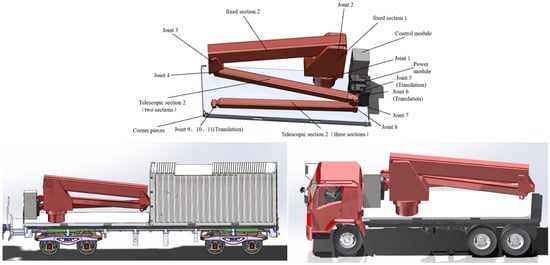
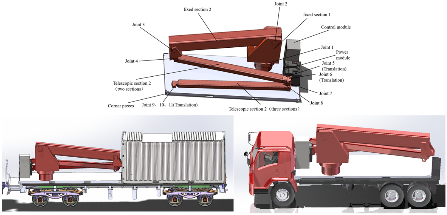
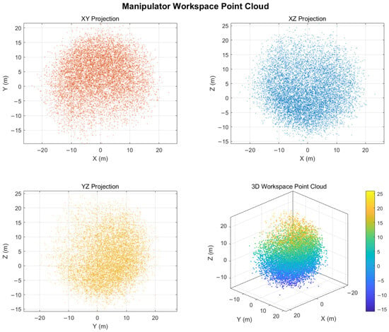
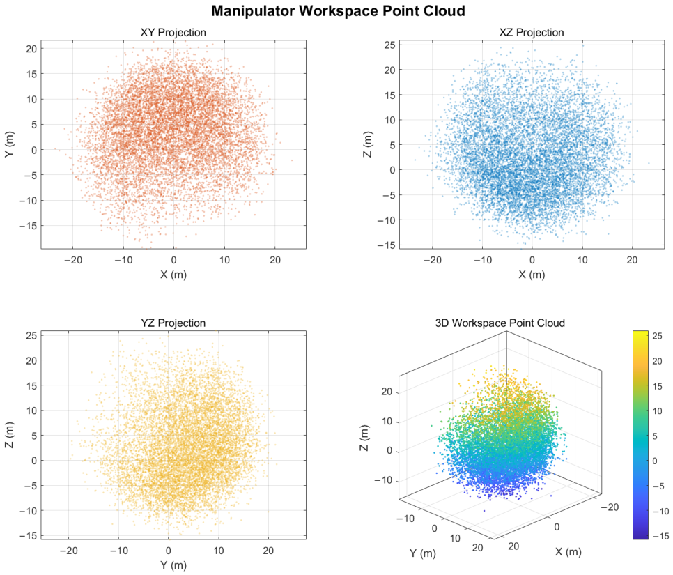
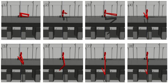
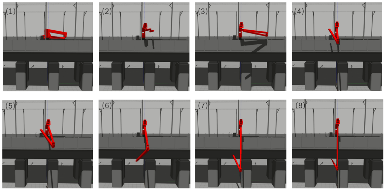
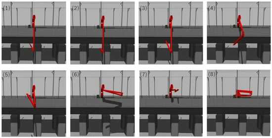
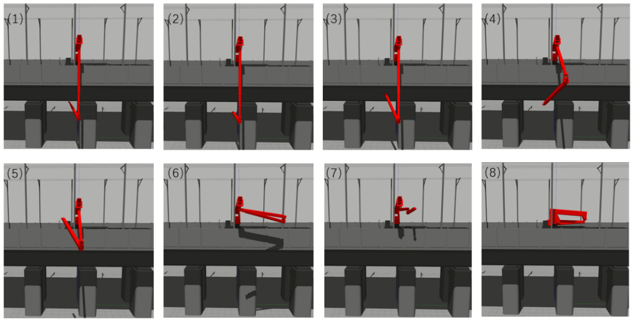
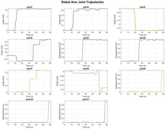
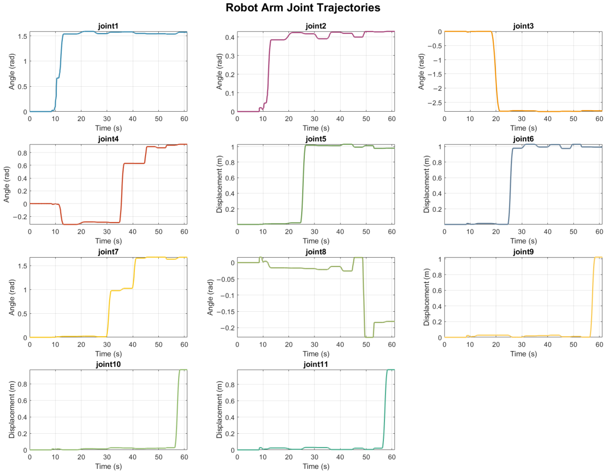
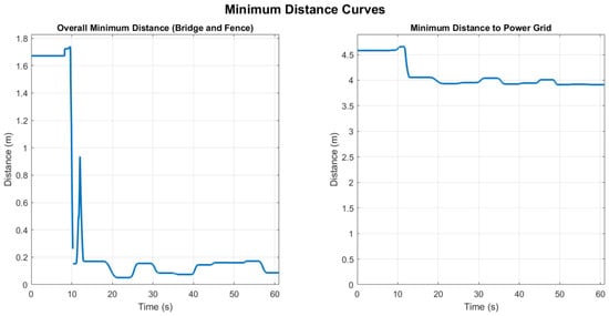
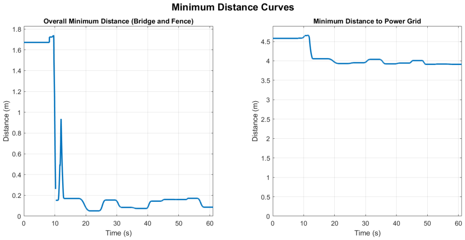
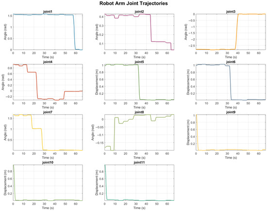
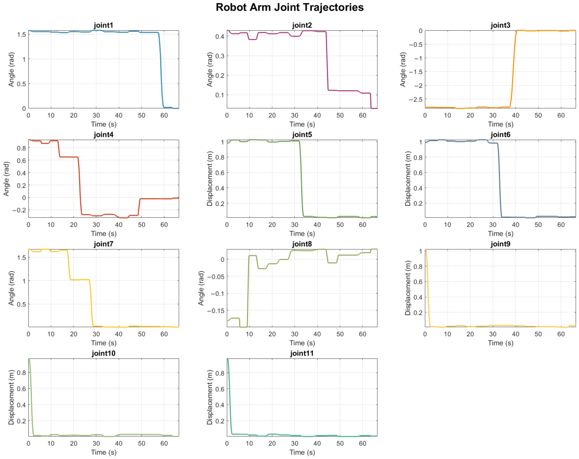
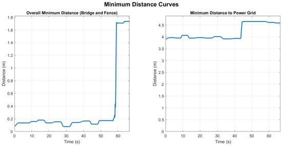
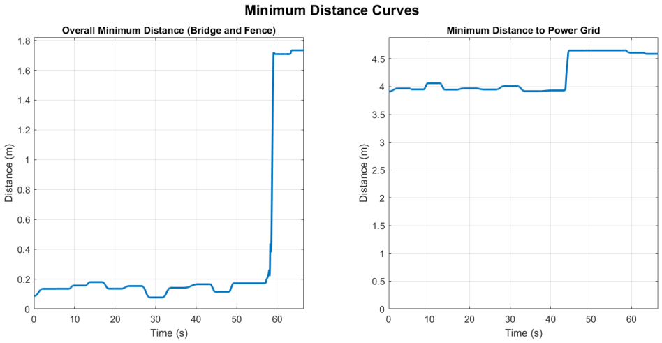
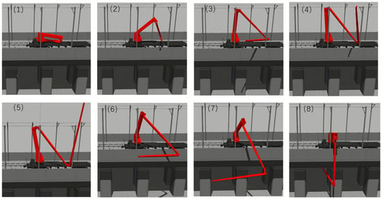
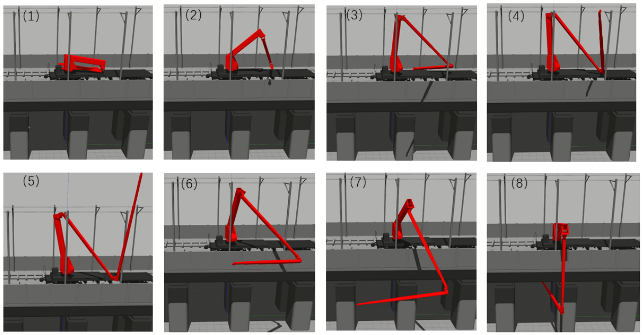
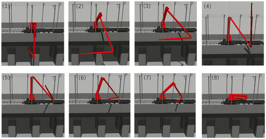
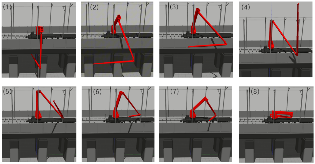
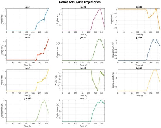
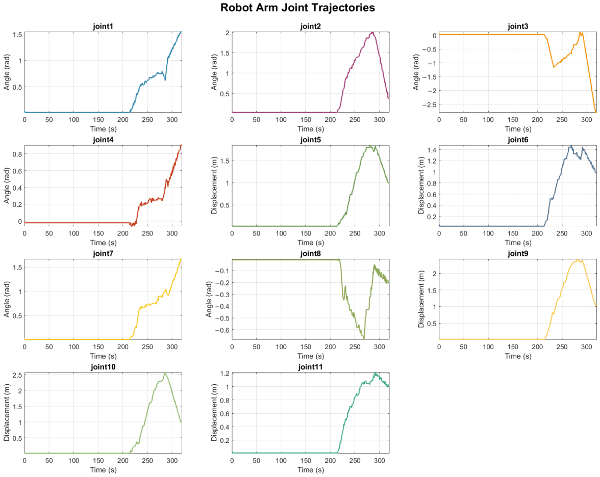
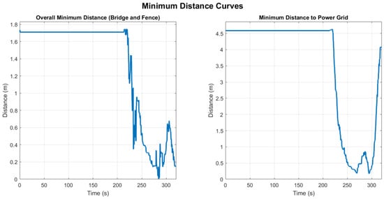
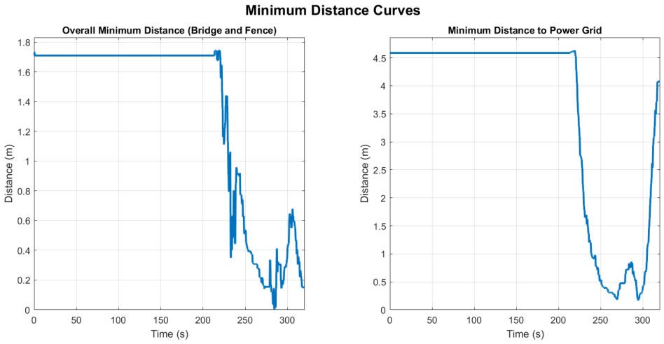
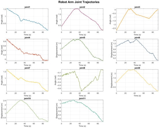
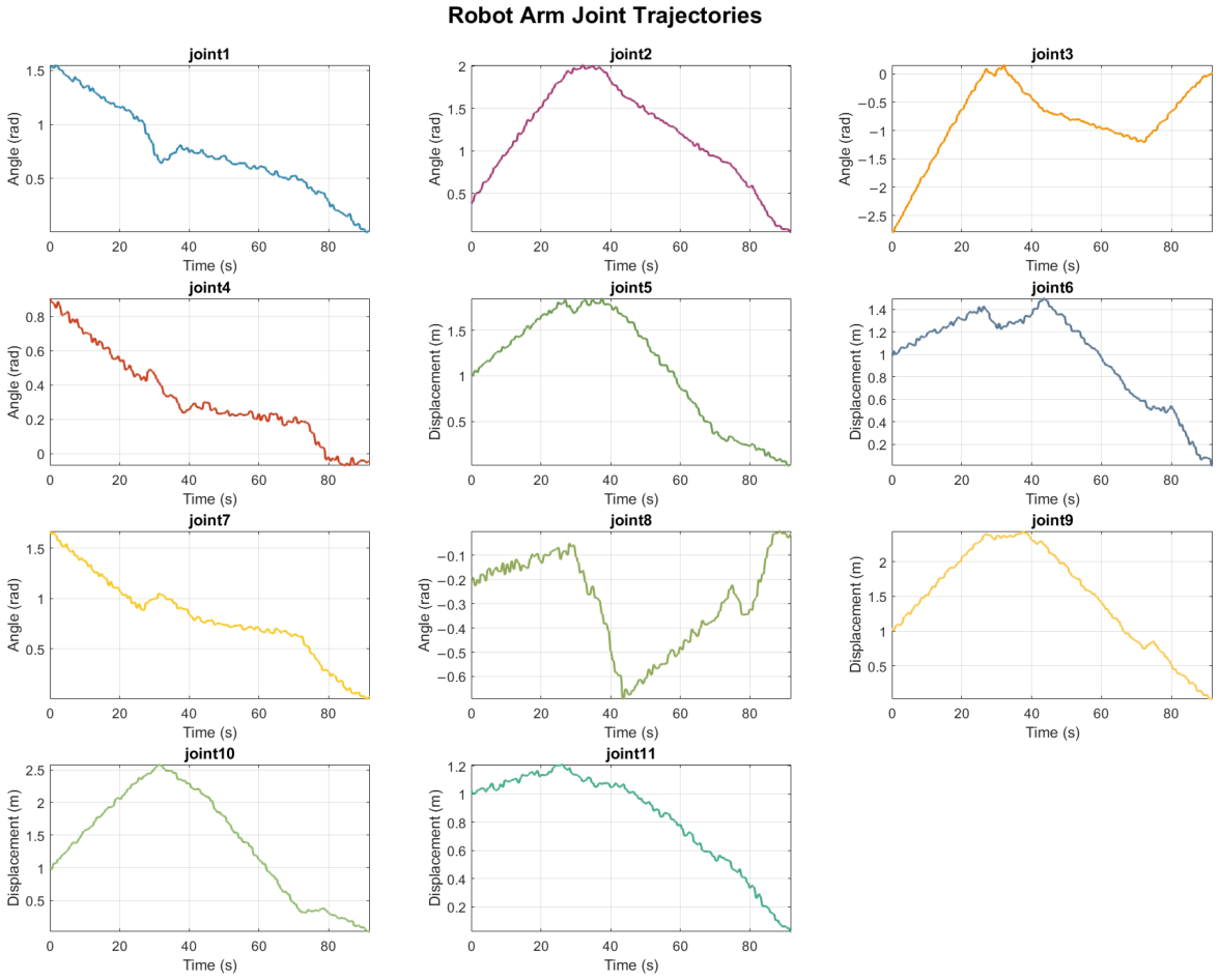
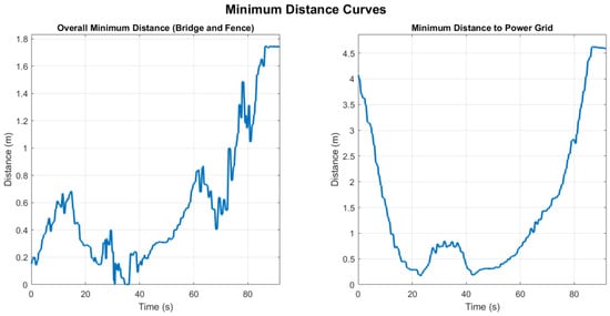
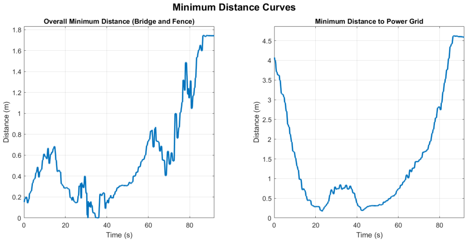
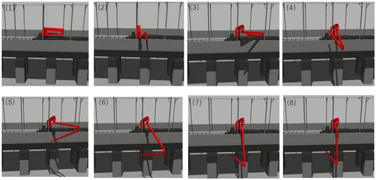
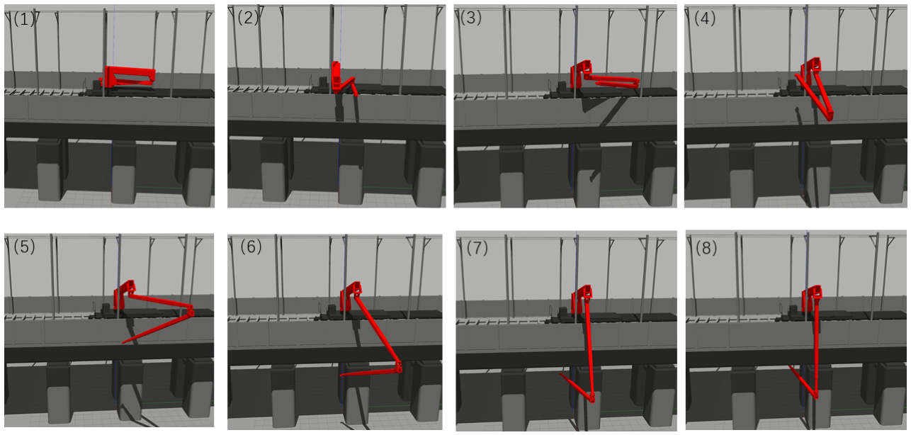
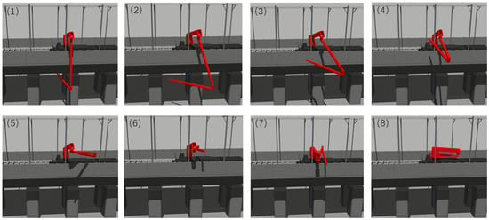
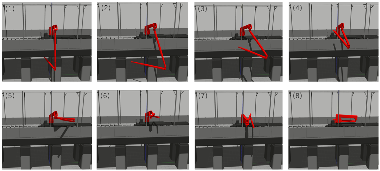
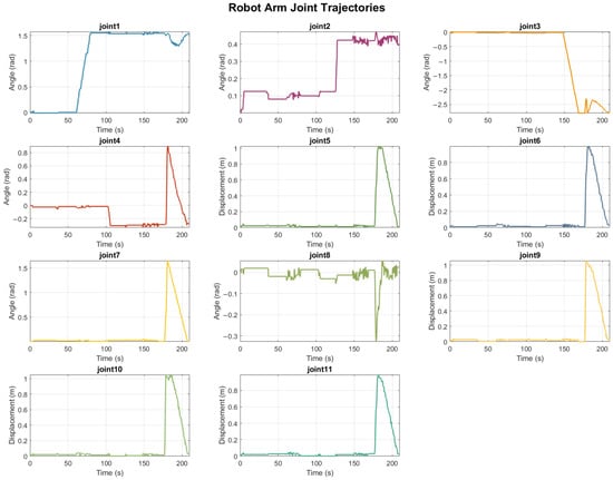
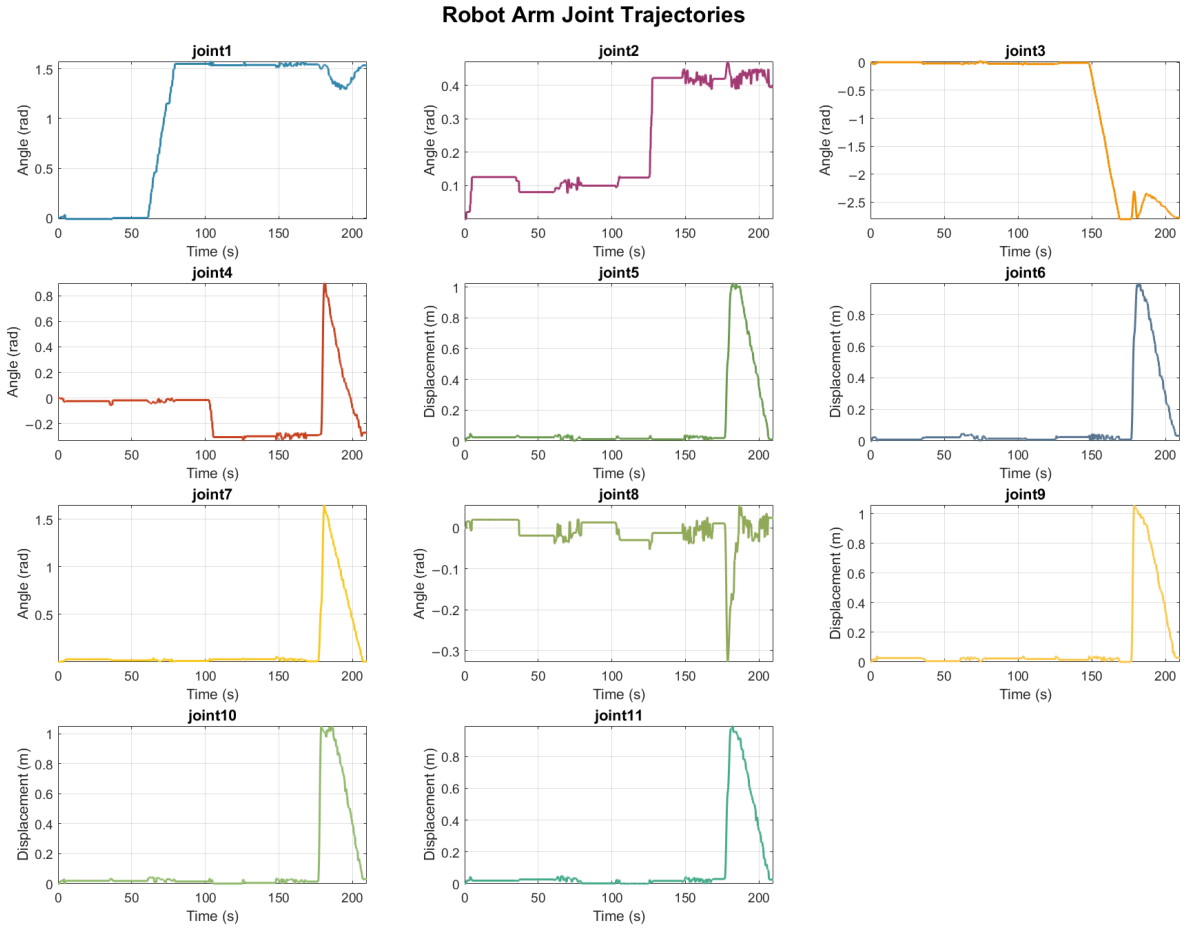
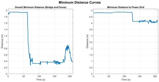
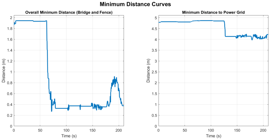
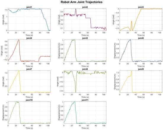
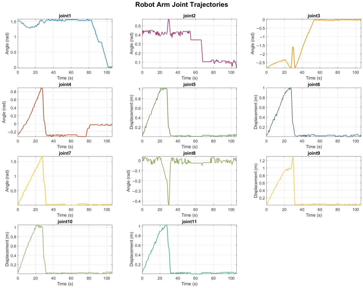
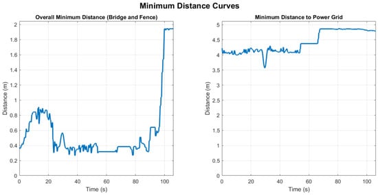
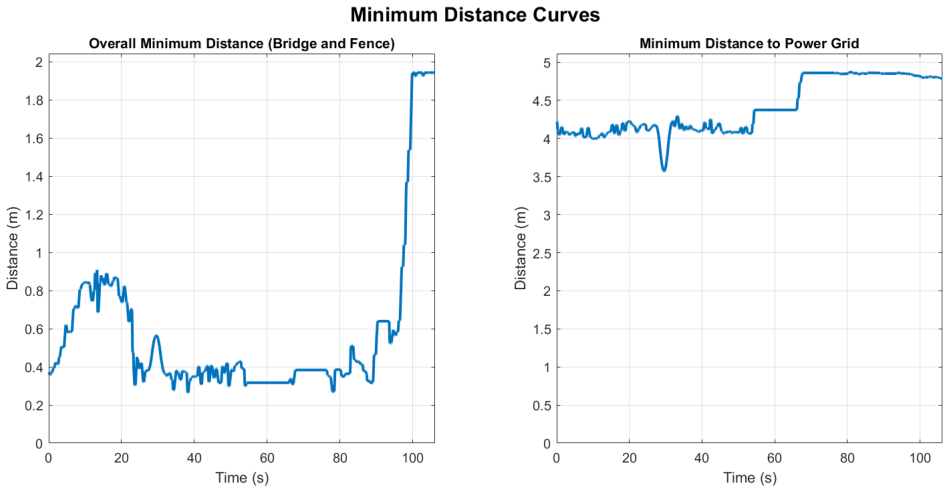
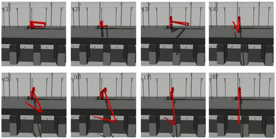
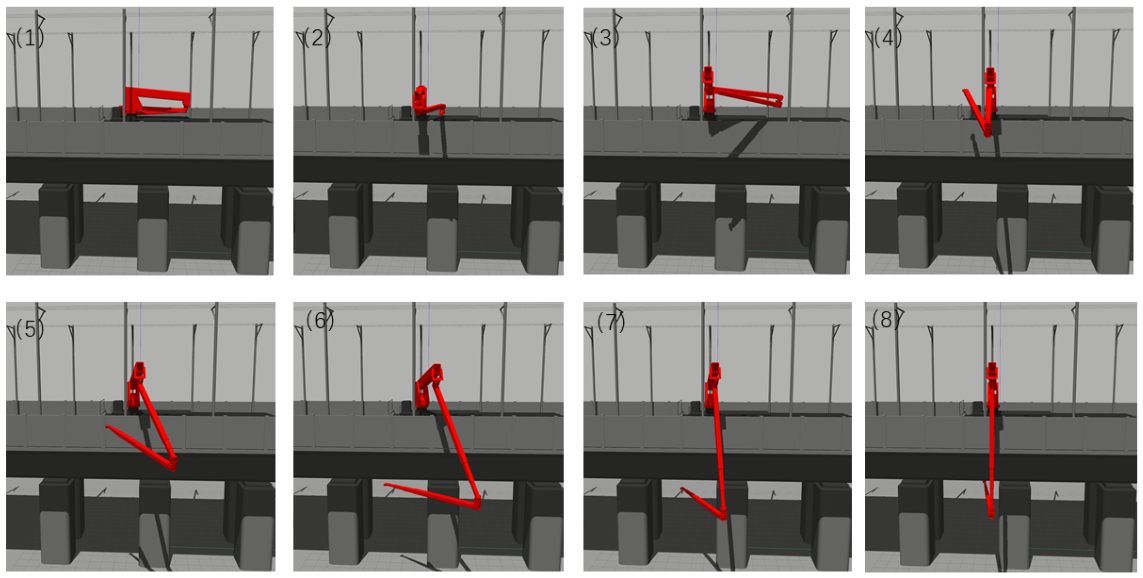
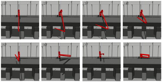
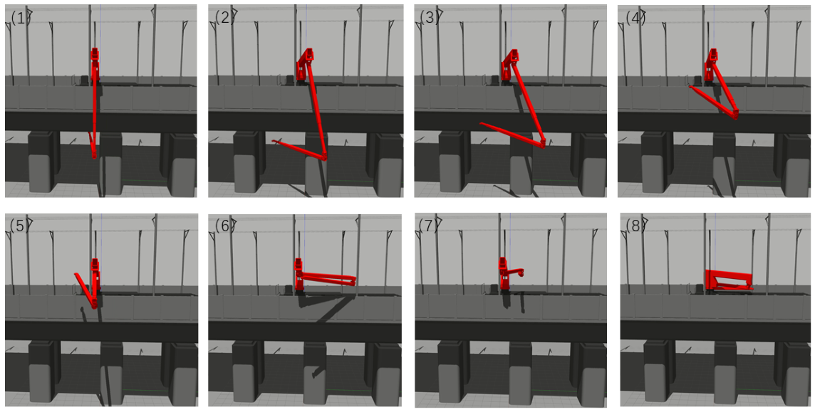
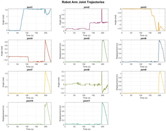
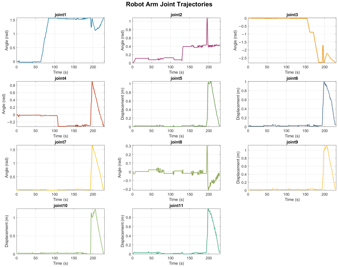
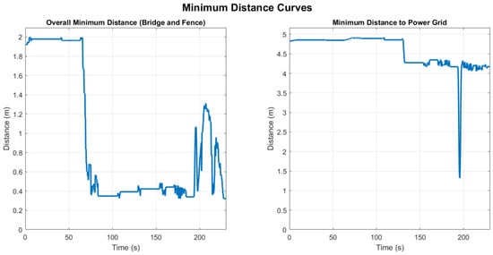
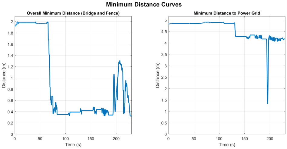
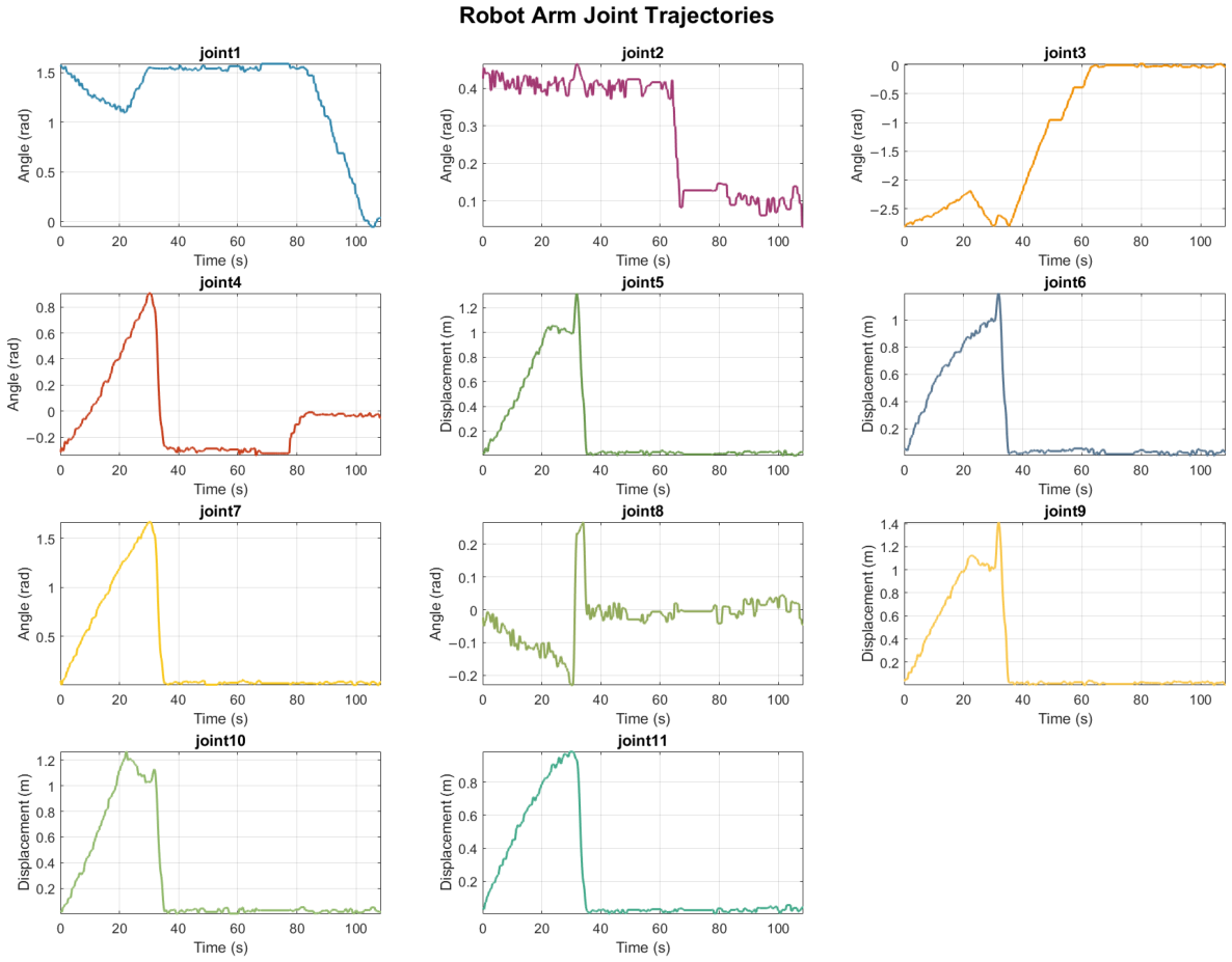
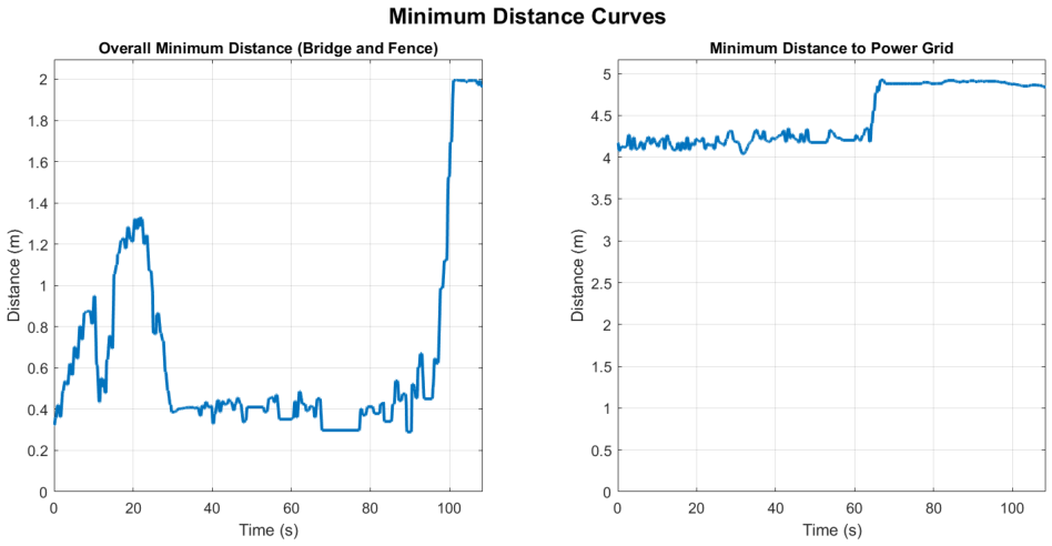

Disclaimer/Publisher’s Note: The statements, opinions and data contained in all publications are solely those of the individual author(s) and contributor(s) and not of MDPI and/or the editor(s). MDPI and/or the editor(s) disclaim responsibility for any injury to people or property resulting from any ideas, methods, instructions or products referred to in the content. |
© 2026 by the authors. Licensee MDPI, Basel, Switzerland. This article is an open access article distributed under the terms and conditions of the Creative Commons Attribution (CC BY) license.