


Abstract
Driving simulators are widely used for vehicle testing, driver training, and rehabilitation, where the quality of immersion depends largely on reproducing realistic motion sensations. However, the kinematic and dynamic limitations of motion platforms, typically based on parallel kinematic mechanisms, prevent full replication of real driving accelerations, particularly in amplitude and duration. This study addresses the challenge of generating controlled head-based force cues associated with part of the inertial loading experienced during driving, which is difficult to reproduce using the motion platform alone. A haptic device concept is proposed to generate such cues, and a feasibility study is carried out to define the specification for future implementation of a robotic system integrated with the driving simulator. Numerical simulations of a race vehicle are performed to characterize the acceleration components relevant to the proposed haptic cueing strategy. Based on these results, a mockup collaborative robotic cell is designed, developed, and coupled, as a first step, with a static simulator, featuring direct real-time control. The work lays the foundation for future industrial development and scaling of robotic haptic systems for advanced driving simulators.
1. Introduction
Driving simulators are human-in-the-loop (HiL) systems, in which a human operator is explicitly integrated into the control loop and the system behavior dynamically depends on ongoing human interaction. Based on inputs from the driver, such as steering, throttle, brake, and gear selection, a numerical model is integrated in real time, and its outputs are used to generate sensory feedback to the user, which may involve visual, auditory, haptic, or motion cues.
Professional driving simulators should be designed for a specific aspect or maneuver, and, for a simulator to be perceived as realistic by the user, it is desirable that the operator is able to identify with the gesture being simulated, with only minor differences compared to performing the same action on an actual vehicle. To accomplish this, the vehicle model must be as accurate as possible, and the real-time sensory feedback should minimize latency to preserve temporal consistency among the sensory cues [1,2].
Realism is also an important feature, as it affects how the user reacts to specific driving conditions. Consistent with the aforementioned considerations, refs. [3,4] show that a limited perception of longitudinal acceleration during braking maneuvers results in driving behaviors differing from those observed under real driving conditions.
To induce realistic driving behaviors, simulators must provide users with multisensory stimulation [5]. This is also supported by [6], showing how direct perception through multiple sensory channels, integrated in space and time, provides a more faithful connection to reality than single-channel perception. However, when a sensory conflict occurs between the signals received by the visual, vestibular, and proprioceptive systems, motion sickness is likely to arise, characterized by a set of unpleasant symptoms such as nausea, dizziness, sweating, and disorientation.
According to the literature review presented in [5], two main forms of motion sickness need to be addressed, as both can compromise user comfort and the overall fidelity of the simulation system. The first arises from insufficient sensory stimulation, as in driving simulators that fail to provide motion feedback to the user. The second comes from inconsistent sensory inputs, such as spurious motion cues generated by a motion platform or delays exceeding 20–50 ms between visual and motion stimuli [1,2].
Considering this evidence, one crucial sensation to reproduce in driving simulators is the sensation of motion, which in most of the existing commercial solutions is reproduced by means of motion platforms based on parallel kinematic machines. These platforms directly stimulate the human vestibular system, which is the organ responsible for perceiving linear acceleration and angular velocity, located in the inner ear [7]. In fact, the trajectory generation for existing platforms, defined by the so-called motion cueing algorithm (MCA), considers the mathematical model of the vestibular system to evaluate the performance of the simulator in terms of motion reproduction, and several advanced MCAs consider this mathematical model in their definition [7]. However, the perception of motion also depends on other stimuli: for example, the perception of velocity increases with auditory feedback, and drivers also perceive acceleration through the muscle responses due to the inertia of the human body. Consequently, the ability to enable multisensory stimulation [5,8] together with haptic/proprioceptive responses would enhance the sensation of motion.
1.1. Limitation of Motion Platforms
According to [9], typical acceleration values during normal driving conditions are less than 0.8 g. On the other hand, in the context of motor racing, the acceleration values can reach 3 g or even higher. The main issue with the use of parallel kinematic machine motion platforms is the limit in maximum exertable acceleration and available workspace, which makes it impossible to completely reproduce linear accelerations both in the cases of passenger and racing cars. Advanced and complex simulators like the DIM400 can reach accelerations of 1.5 g in the longitudinal and lateral directions [10], while for compact simulators, the maximum reachable acceleration is lower than 1 g. Nevertheless, the exposure time to acceleration is inherently limited by the length of the robotic actuators and the width of the workspace. These factors make it difficult to reproduce sustained accelerations in the longitudinal and lateral directions.
A technique used to partially reproduce these accelerations is called tilt coordination, which involves tilting the platform to create a gravitational component that matches the sustained acceleration to be replicated (see Figure 1). However, this technique has some limitations. One is that the tilt rate must be below a certain threshold; otherwise, the user will recognize the angular motion rather than the linear acceleration due to the gravity component [11]. Another limitation is the so-called Aubert effect, in which a distortion of the perceived vertical, that is, the individual’s perception of the gravitational component along their local vertical axis, can occur for tilt angles that exceed 20–30 degrees [12]. Hence, the accelerations simulated by tilt coordination should not exceed 0.34–0.5 g.
Figure 1.
Tilt coordination technique representation.
1.2. Existing Haptic Solutions for Motion Perception
Localized haptic stimulation has been investigated as a means of complementing visual motion cues without reproducing the displacement of the whole body. Existing approaches include vibrotactile stimulation, mechanically transmitted force feedback, and airflow-related stimulation. These modalities should be distinguished according to the physical stimulus delivered: a directional vibration pattern encodes a motion cue, whereas a sustained external force mechanically loads the head-neck system. Likewise, airflow directed onto the user differs from the reaction forces generated by head-mounted air jets or propellers [13]. In driving simulators, Yu et al. [14] developed a headband with vibrotactile actuators to enhance motion sensation by using simulated acceleration telemetry data to generate directional vibrations. A study with 24 participants demonstrated that this solution increased the realism and immersion of the simulation. Similarly, Liu et al. [15] integrated six air jets into a VR headset to provide controlled propulsion forces on the user’s head, significantly extending the perceived acceleration duration beyond what a motion platform alone can achieve. Related approaches using fans mounted on VR headsets are described in Hoppe et al. [16] and Watanabe et al. [17].
In addition to these wearable solutions, robotic systems have been applied to provide haptic force feedback. For example, Costes and Lécuyer [18] reported the use of a 6-DOF robotic arm in a flight simulator, connected to a head-mounted display, which delivered real-time force feedback. Their study showed that video-haptic rendering induces more vivid sensations of self-motion than video alone. While this approach has not yet been widely applied to driving simulators, it suggests a promising direction once domain-specific requirements are formalized.
Beyond driving simulation, several head-haptic robotic devices have been developed for training and rehabilitation purposes. Wu et al. [19] implemented a 6-DOF parallel kinematic machine connected to the user’s head via a helmet. The system combined an inverse dynamic controller with electromyography signals to estimate neck forces, assisting head and neck motion while reducing contact forces. Similarly, Koszulinski et al. [20] designed a cable-driven robot to support rehabilitation of the head–neck joint, allowing a wide range of motion. The device features two concentric crowns connected via revolute and sliding joints: the outer crown provides motion, while the inner crown adapts to the user’s head. Motor positions were optimized to minimize cable tension and maximize dexterity, resulting in a flexible device with high dynamics and a broad workspace. Another rehabilitation-focused solution is presented by Zhang et al. [21], which uses a robotic neck brace for patients with neurological disorders such as cerebral palsy and amyotrophic lateral sclerosis. The soft headband is attached to shoulder pads through three actuated supports, with a force PID controller generating spring-like reactions to guide the head along a desired trajectory, complemented by a visual interface to encourage correct movements.
1.3. Aim of the Work
The specific contribution of this work is a driving-oriented design and preliminary experimental characterization framework that links vehicle acceleration spectra to bounded longitudinal and lateral force references, examines the mechanical implications of the robot–helmet attachment geometry for moment loading about the approximate cervical joint center, and evaluates force-tracking behavior under fixed-helmet and preliminary human-driving conditions. The purpose is to study and assess the requirements for a robotic system capable of generating force feedback on the driver’s head, based on the configuration presented for flight simulators by Costes and Lécuyer [18]. The referenced work describes a robot connected to a helmet that enhances motion perception by applying controlled forces to the user’s head.
In the present paper, referring to the driving simulator domain, the robotic system is experimentally characterized in low-force tests, demonstrating the technical feasibility of applying controlled low-frequency force cues to the driver’s helmet. The force exerted by the robot is intended to reproduce part of the inertial loading acting on the driver’s head, thereby complementing the motion cues provided by conventional motion platforms when their finite workspace limits the reproduction of sustained accelerations. This work seeks to establish design guidelines for future customized designs.
The first contribution of the work is the definition of a preliminary safety-oriented design framework for intentional robot interaction with the human head–neck complex. Biomechanical literature concerning neck loading, head acceleration, impact-related injury criteria, and physiological range of motion is combined with the provisions of ISO 10218-2:2025 relevant to collaborative robotic applications. Biomechanical and standards-based reference values are identified together with preliminary design constraints for force, torque, pressure, linear and angular acceleration, and robot workspace.
The second contribution is the definition of the force cue to be generated by the robotic system. Telemetry data acquired from racing simulations are analyzed in both the time and frequency domains to characterize the longitudinal and lateral accelerations acting at the driver’s head. Based on this analysis, a processing architecture based on saturation, low-pass filtering, and force scaling is developed to convert vehicle acceleration into a bounded robot force reference.
The third contribution is the development and experimental characterization of a physical prototype based on a six-degree-of-freedom collaborative manipulator equipped with a wrist force–torque sensor and mechanically connected to a racing helmet. The robot is operated under direct force control and receives updated longitudinal and lateral force references from the driving simulation through a soft real-time communication architecture. Particular attention is devoted to the robot–helmet connection, the application point of the force, workspace constraints, and the resulting mechanical loads on the head–neck system.
Finally, the dynamic response of the robotic interface under a fixed-boundary condition is experimentally characterized, and preliminary driving tests are performed at a low end-effector force level to examine the force-tracking behavior and verify the basic feasibility of the proposed approach. The present work does not aim to demonstrate perceptual effectiveness or improved immersion, which will require dedicated human-subject experiments. Instead, it establishes the mechanical and control foundations, together with safety-related design considerations, required for the subsequent development and evaluation of collaborative robotic head-haptic systems for driving simulation.
Section 2 reviews safety-related design considerations for mechanisms interacting with the human head. Biomechanical literature and relevant standards are used to identify reference values and preliminary design constraints related to neck and brain injury, head motion, and applied loads.
Section 3 focuses on characterizing the range of accelerations perceived by drivers in a racing car and defining the data processing procedure used to generate the reference force for the robot. A time-domain and frequency-domain analysis of acceleration data gathered from a high-fidelity racing simulator is carried out to determine the specifications of the reference force to be applied to the driver’s head.
In Section 4, an experimental setup is developed using a 6-DOF serial collaborative robot equipped with a force–torque sensor mounted on its wrist, enabling operation in force-control mode. In this setup, the robot end effector is connected to a driving helmet to apply force cues associated with the modeled translational inertial component during acceleration, braking, and cornering maneuvers. This section also describes the safety implementations adopted for the setup and the control of the collaborative robot.
Section 5 details the robot control logic implemented, followed by the characterization of the control frequency performed through experimental testing. Section 6 presents and analyzes the results of the real-time experimental tests conducted using the proposed solution as a haptic feedback system in a driving simulator. Section 7 discusses the outcomes of the work, including considerations for future developments and integration with a motion platform. Finally, Section 8 summarizes the conclusions of the study.
2. Head–Robot Safety Considerations
A literature review was conducted to identify safety-related design considerations and biomechanical reference values relevant to the proposed robot–human head interaction system. This review focuses on three main aspects: neck injuries resulting from exposure to external and/or inertial loads on the head–neck; brain injuries, which are mainly associated with impacts [22] and head kinematics [23,24]; and the ISO 10218-2:2025 standard [25], which defines general safety requirements for industrial robot applications and robot cells, including provisions relevant to collaborative operation and human–robot contact. In addition, anthropometric literature on the range of motion of the human head has been reviewed to define preliminary workspace constraints intended to avoid exceeding the physiological range of head motion.
2.1. Neck Injury Studies
The motivation for this subsection is to review biomechanical evidence related to external force, moment, and acceleration loading of the head–neck complex. These data provide reference values for the preliminary design of the haptic robotic-head system.
Neck injuries are a significant concern for car drivers, pilots, and participants in high-risk sports (e.g., football) due to the potential for accidents. To determine the causes of these injuries and to establish kinematic and dynamic limits, several authors have conducted tests on cadavers, volunteers, and physical models. For example, Siegmund and Blouin [26] studied the effect of high jerk during low-speed vehicle collisions on the risk of whiplash injury, a condition resulting from rapid and forceful back-and-forth movement of the neck. They concluded that jerk plays little or no role in whiplash injury, in contrast to sled acceleration and speed change, which strongly affect muscle activation and kinematic responses.
Biomechanical values relevant to cervical loading have been summarized in the literature review provided by Coakwell et al. [27]. The study aimed to prevent cervical spinal injury associated with high-performance flight practice in aircraft, where aviators are subjected to high sustained accelerations. Considering the cervical spine sagittal plane model [28], it was reported that the neck can support maximum acceleration loads of 30 g, 24 g, and 15 g along the longitudinal direction when the neck is in its neutral, fully flexed, and fully extended positions, respectively. However, Coakwell et al. [27] cites several references indicating that accelerations above 4 g have been associated with possible neck injuries, based on surveys of high-performance aviators who reported the onset of symptoms in the 4–9 g range. Assuming that the head–neck mass corresponds to approximately 6.7% of total body mass [29], and considering body weights of 50–100 kg with an additional 1.8–2.2 kg for headgear (e.g., helmet, visor, mask), the corresponding translational inertial-force estimate for the combined head–neck and headgear mass at 4 g acceleration would range from approximately 200 to 349 N.
Finally, ref. [27] reports maximum resistance moments of 65.1 Nm (men) and 53.4 Nm (women) for the extensor muscles, and 36.5 Nm (men) and 32.4 Nm (women) for the flexor muscles.
These quantities are retained as literature-derived biomechanical reference values and are not interpreted as validated safety thresholds for the robotic application.
2.2. Brain Injury Studies
This subsection aims to identify the kinematic and dynamic conditions that may cause brain injury, as the proposed robotic system could potentially generate accelerations or impacts on the user’s head. The focus is on well-established biomechanical indices that quantify head injury risk.
Post and Hoshizaki [30] summarize the main mechanisms of brain injury, including skull deformation, intracranial pressure gradients from impacts, and relative skull–brain motion caused by linear and rotational accelerations. Several quantitative indices have been proposed to assess these risks. The Gadd Severity Index (GSI) and the Head Injury Criterion (HIC) are based on the linear acceleration of the head, , over time. The former (GSI) mathematically extends the empirical Wayne State Tolerance Curve (WSTC), which relates the magnitude and duration of head linear acceleration to a threshold for concussion or severe head injury. Since GSI considers pulses of 50 ms, which are longer than actual head impact durations, the latter criterion (HIC), adopted by the National Highway Traffic Safety Administration (NHTSA), is preferred for short-duration impacts. Injury thresholds are set at 1000 for both indices, with time windows of 36 ms (NHTSA) or 15 ms (ISO) [30]. The GSI and HIC are calculated as shown in Equations (1) and (2), respectively.
The Generalized Acceleration Model for Brain Injury Threshold (GAMBIT) combines linear and angular head accelerations in an injury-related criterion. For the linear GAMBIT formulation reported by Newman [31], the parameters considered here are , , and . Here, and denote the resultant linear and angular head accelerations, respectively, with expressed relative to g and in . The GAMBIT criterion is defined by the maximum value of over the considered event, with the function specified in Equation (3). A value of represents a literature-derived injury reference level and is not interpreted in the present work as a validated safety limit for repeated intentional head–robot interaction. GAMBIT was not calculated or used as an operational limit in the present experiments because the required head angular kinematics were not measured.
Another widely used metric is the Head Impact Power (HIP), which quantifies the rate of change of kinetic energy. Reconstructions indicate that a HIP of 12.8 kW corresponds to a 50% probability of mild traumatic brain injury (mTBI) [30]. For preliminary design purposes, a HIP value of 6 kW, corresponding to less than half of this reported level, was retained as a reference value rather than as a validated safety threshold for repeated head–robot interaction. HIP is calculated as shown in Equation (4), where and are the mass and tensor of inertia of the human head:
Based on literature data, angular accelerations above 1800 and linear accelerations above 80–90 g without helmet protection are associated with mTBI, although higher values are tolerated in American football due to helmet usage [30].
HIC, GAMBIT, HIP, and angular acceleration are therefore retained here as literature-derived injury-related reference criteria rather than as validated operational limits for the present robotic application.
2.3. Relevant Collaborative Robot Standard
To the authors’ knowledge, no specific standard has been identified that directly addresses intentional physical interaction between an industrial robot and the human head–neck complex in the context considered in this work. The most relevant general standard is ISO 10218-2:2025 [25], which specifies safety requirements for the design, integration, commissioning, operation, maintenance, decommissioning, and disposal of industrial robot applications and robot cells. Within this broader framework, the standard includes requirements for collaborative applications and for the assessment and reduction of risks arising from foreseeable physical contact between a person and a robot application.
This subsection examines the provisions of ISO 10218-2:2025 that are most relevant to the present work. Clause 5.14 addresses collaborative applications, including risk-reduction measures for quasi-static and transient contact between a person and moving parts of a robot application. A quasi-static contact occurs when a body region is constrained or clamped between a moving part of the robot application and another surface, such that the affected body region cannot move freely away from the contact.
Risk-reduction measures may be passive or active. Passive measures reduce the mechanical severity of a possible contact by modifying the geometry or material properties of the robot application. Examples include increasing the contact area, rounding edges and corners, covering rigid surfaces with compliant materials, and incorporating energy-absorbing elements to distribute or dissipate the contact load. Active measures modify the behaviour of the robot application through monitored control functions, for example by limiting its velocity, force, power, momentum, or kinetic energy. These measures are intended to ensure that foreseeable contact remains within the limits established through the application-specific risk assessment.
More specifically, Clause 5.14.6 addresses power- and force-limited collaborative applications. The associated biomechanical reference limits for quasi-static and transient contact are provided in Annex M, entitled “Limits for quasi-static and transient contact.” For quasi-static contact, Annex M specifies force reference limits of for the skull and forehead and for the neck. It also provides quasi-static pressure reference limits of for the middle of the forehead and for the temple.
The force and pressure limits represent different biomechanical constraints and must therefore be assessed separately. The force limits are intended to reduce the likelihood of mechanically induced tissue or skeletal injury, such as penetration, bleeding, or fracture. In contrast, the pressure limits are based primarily on experimentally determined pain-onset thresholds for specific body regions. Compliance with one type of limit does not imply compliance with the other; both the contact force and the local pressure must be considered, together with the contact geometry, duration, body region, and potential for clamping.
The values reported in Annex M are therefore retained here as body-region-specific biomechanical reference values relevant to preliminary design and risk assessment. They are not interpreted as validated allowable levels for repeated intentional head–robot loading. Definition of operational safety limits for the present application would require a dedicated risk assessment and validation of the implemented human–robot interface under the intended operating conditions.
2.4. Biomechanical Reference Values and Preliminary Design Constraints
Table 1 summarizes the biomechanical and standards-based reference values identified in the preceding review. These values should not be interpreted as a single set of validated operational safety limits. Cervical-loading and contact-related values are retained as references relevant to preliminary design and risk assessment, whereas HIC, GAMBIT, HIP, and head angular acceleration were reviewed as injury-related criteria but were not used for experimental safety supervision. GAMBIT, HIP, and head angular acceleration could not be fully evaluated because head angular kinematics were not measured. For the present robot–helmet configuration, the head-related force and pressure references are the most relevant contact values; neck-related values are also reported for completeness and would become more directly relevant if the interaction configuration were changed to load the neck region. None of these contact reference values is adopted as a validated operational limit for repeated intentional loading.
Table 1.
Biomechanical and contact reference values considered for preliminary robot–head application design.
In addition to these biomechanical and contact reference values, the robot workspace was constrained according to the reported range of motion of the human head–neck complex. To establish a limit value, the study conducted by Ferrario et al. [32] was considered, which provides statistical data on the angular displacements of the head–neck complex along the sagittal, frontal, and horizontal planes. From this study, the mean value minus one standard deviation of the roll (frontal) and pitch (sagittal) head movements was used to define preliminary workspace limits. These values are summarized in Table 2 (male statistical data were considered since males exhibit a smaller range of motion than females).
Table 2.
Average head–neck range of motion for male subjects and selected preliminary limits for robot workspace definition. All angular values are expressed in degrees.
3. Data Analysis and Force Reference Definition
To determine the reference forces that the robotic system must exert on the driver’s head, acceleration data analysis was first performed based on numerical simulations carried out using Assetto Corsa, a high-fidelity racing simulator with realistic vehicle dynamics. Since the objective is to reproduce the inertial forces acting on the driver’s head, the modeled translational force was assumed to be equal to the product of the combined head–neck mass and the linear acceleration of the driver’s head, with the helmet mass added for the helmeted configuration considered in this work. Under this assumption, the driver’s body is regarded as rigidly coupled to the seat by safety belts, meaning that the computed force represents a simplified estimate of the translational inertial component acting on the head–neck system. Rotational inertial contributions associated with head angular motion, as well as neck muscle and joint dynamics, are not included in this model, since head angular kinematics were not measured in the present study. Forces were analyzed only in the horizontal plane (representing longitudinal and lateral accelerations), while vertical accelerations, mainly caused by tire–road interactions, were neglected, as they are typically damped by the seat to preserve comfort [33].
The analyzed data were obtained from telemetry acquisitions using Assetto Corsa. In this phase, 14 participants each completed one lap of the Spa–Francorchamps Formula 1 circuit (see Figure 2), which has a total length of approximately 7 km and includes several high-speed sections and corners. The extracted telemetry data corresponded to the car chassis’ linear acceleration and angular velocity, both referenced to the vehicle’s center of mass.
Figure 2.
Top view of the Spa–Francorchamps circuit.
To compute the linear acceleration at the driver’s head position, a fixed offset between the head and the car’s center of mass was assumed. The linear acceleration of the driver’s head can thus be expressed as shown in Equation (5), where denotes the car’s linear acceleration, the angular velocity of the car chassis, and the constant position vector from the car’s center of mass to the driver’s head (in this case equal to [−0.118, 0, 0.721] m for the longitudinal, lateral, and vertical components). All quantities are expressed in the vehicle’s local reference frame.
Equation (5) can be divided into two main contributions: the first term corresponds to the translational acceleration of the chassis, while the remaining terms represent the linear-acceleration contribution induced by vehicle-chassis rotation at the assumed head position.
A spectral analysis of both components was performed for each data set using the Welch power spectral density (PSD) method. The telemetry sampling interval was s ( Hz). For each acquisition containing N samples, the PSD was estimated in MATLAB R2025b using pwelch with a periodic Hamming window of length samples and 50% overlap ( samples). The DFT length was set to the next power of two not smaller than , with a minimum of 256 points. No explicit detrending or mean removal was applied before calling pwelch.
The results are presented in Figure 3. The left panels (a and c) illustrate the PSD of the longitudinal and lateral head accelerations, respectively, induced by car translation, while the right panels (b and d) show the corresponding PSDs associated with car rotation.
Figure 3.
Power spectral density (PSD) of the driver’s head acceleration induced by car translation and rotation, obtained from 14 acquisitions (one lap from each of 14 participants) on the Spa–Francorchamps circuit. (a) PSD of the longitudinal head acceleration due to car translation; (b) PSD of the longitudinal head acceleration induced by vehicle-chassis rotation; (c) PSD of the lateral head acceleration due to car translation; (d) PSD of the lateral head acceleration induced by vehicle-chassis rotation.
On average, most of the spectral power associated with translational accelerations is concentrated below approximately 0.6 Hz, whereas the linear-acceleration contributions induced by vehicle-chassis rotation are mainly concentrated between 3 and 9 Hz. Furthermore, the peak PSD values of the translational acceleration contributions are approximately two orders of magnitude higher than those induced by vehicle-chassis rotation, in both the longitudinal and lateral directions. Therefore, the translational acceleration signals were selected for subsequent low-pass filtering and force-reference generation.
To guide the low-pass-filter tuning, the cumulative spectral power of the selected translational acceleration components was examined. On average, approximately 84% and 94% of the longitudinal and lateral translational spectral power, respectively, were contained below 0.6 Hz. These fractions increased to approximately 89% and 96% below 1 Hz, and to approximately 91% and 98% below 1.5 Hz. Based on these results, a practical cutoff-frequency tuning range of approximately 0.6–1.5 Hz was considered.
Figure 4 shows the time-domain linear accelerations of the car chassis for one of the 14 acquisitions. The longitudinal acceleration (panel a) varies between g and g, while the lateral acceleration (panel b) ranges between g and 3 g. Similar limits were observed across all acquisitions. These acceleration ranges motivate the investigation of complementary haptic force cues, particularly for sustained acceleration conditions that are difficult to reproduce using motion platforms with finite workspace.
Figure 4.
Time-domain linear accelerations of the car chassis for one acquisition on the Spa–Francorchamps circuit. (a) Longitudinal car acceleration; (b) Lateral car acceleration.
According to Dumas et al. [29], the combined head and neck mass represents approximately 6.7% of the total body mass. Therefore, considering a user weight range of 50–100 kg and including a 1.5 kg helmet, the translational inertial-force estimate obtained from the simplified model, corresponding to 3 g of acceleration, would be approximately 140–240 N. This simplified inertial-force estimate does not define the force commanded by the robot. The maximum commanded end-effector force, , is instead treated as a separate application-specific operating parameter, subject to an appropriate risk assessment.
Robot Reference Signal Algorithm
The following description corresponds to the algorithm implemented to generate the force reference for the collaborative robot, starting from the vehicle acceleration outputs provided by the car dynamic model (i.e., Assetto Corsa). The algorithm has been defined according to the previous analysis performed on the acquired simulation data.
The algorithm takes as input the longitudinal and lateral accelerations of the vehicle (as described in the present section) and processes them through a saturation block that considers the expected maximum acceleration values for the application case. For the driving scenario considered in this study, the limits are set to for longitudinal acceleration and for lateral acceleration. This step limits the influence of extreme acceleration peaks on the generated reference signal.
The saturated signals are then filtered using a first-order Butterworth low-pass filter with a cutoff frequency of in the reported experiments, selected within the – tuning range identified from the preceding spectral analysis. This choice represents a trade-off between preserving the dominant low-frequency translational acceleration content, attenuating higher-frequency components, and limiting filtering-induced phase delay.
Finally, the filtered data are scaled by a gain that relates the selected maximum commanded end-effector force per component to the acceleration bound used for scaling. The gain is defined as the ratio between the selected maximum end-effector force per component, , and , where is the largest absolute value of the saturation bounds for the corresponding axis. In the present implementation, for both the longitudinal and lateral directions, giving a gain of for each component. For the specified saturation and filtering stages, this scaling bounds the magnitude of each commanded force-reference component by . Consequently, the magnitude of the resultant commanded force can reach if both components simultaneously attain their maximum absolute values.
The general data processing architecture is represented in Figure 5. The processing stages are applied in this order to bound the input accelerations, attenuate higher-frequency variations through low-pass filtering, and set the force-reference amplitude separately for each direction.
Figure 5.
Scheme of the robot reference generation algorithm.
This modular structure allows the maximum end-effector force per component to be configured according to the intended application, subject to an appropriate application-specific risk assessment.
In Figure 6, different processing stages are presented for one of the acquisition datasets, taking the longitudinal acceleration signal as a reference to illustrate the previously described algorithm. The upper subplot (panel a) shows the modeled longitudinal translational-force estimate, calculated by multiplying the vehicle longitudinal acceleration by an assumed combined head–neck mass corresponding to of a subject, plus a helmet, resulting in a total modeled mass of . The middle subplot (panel b) shows the saturated, low-pass filtered force, obtained using the first-order Butterworth filter with and shown before application of the final force-scaling gain. Finally, the bottom subplot (panel c) corresponds to the force reference adjusted with a gain to set the maximum longitudinal force-reference component to in this illustrative processing example. The assumed mass is used to illustrate the modeled inertial-force estimates, whereas the final robot force reference is obtained directly from the filtered acceleration using the previously defined scaling gain.
Figure 6.
Longitudinal force-reference processing for one acquisition on the Spa–Francorchamps circuit: (a) modeled longitudinal translational-force estimate obtained using the combined head–neck and helmet mass; (b) saturated and low-pass filtered force using , before final force scaling; and (c) filtered and scaled longitudinal force reference with a maximum commanded component value of in this illustrative example.
4. Experimental Setup
A prototype was developed using a collaborative robot to investigate the application of longitudinal and lateral force cues to the driver’s head in real time based on the acceleration output from the driving simulation.
The solution developed for experimental deployment uses the commercial software Assetto Corsa as a dynamic simulator, integrated with the Logitech G27 steering wheel and pedals. The latter serve as human–machine interfaces that provide input to the real-time numerical simulation.
The motion data of the car chassis are extracted from the numerical simulation at a sampling frequency of 166.67 Hz using the shared memory interface of Assetto Corsa. These data are then processed by the algorithm presented in Section 3, executed on the same PC running Assetto Corsa in a separate high-priority thread. Through real-time telemetry access via shared memory, the algorithm generates the reference force to be applied by the collaborative robot to the driver’s helmet during driving.
The robotic manipulator used is a Mitsubishi Electric Melfa Assista RV-5AS-D, a collaborative 6-DOF manipulator, which operates together with the CR800-05VD controller unit [34]. The robot is equipped with a Mitsubishi 4F-FS002H-W200 force sensor, used to implement force-feedback control for tracking the prescribed force reference through Mitsubishi’s Force Sense Control (FSC) function [35] (see Section 5). The sensor has a maximum rated force and torque of 200 N and 4 Nm, respectively, for each axis. The force reference is sent to the robot controller through the TCP/IP protocol at 50 Hz after resampling the processed data. This architecture provides software-based, soft real-time coordination of the force-reference updates, without explicit clock synchronization between the driving simulator and robot controller or guaranteed deterministic end-to-end timing. Because temporal alignment is important for the intended haptic cues, future developments will investigate explicit synchronization and end-to-end latency monitoring to improve timing predictability and system robustness. This mechanism is connected to a carbon fiber helmet to transmit the exerted force to the user’s head. The mentioned setup is shown in Figure 7.
Figure 7.
Experimental setup: (a) close-up view of the robot–helmet interface. (b) overall view of the setup with the robotic system, steering wheel, and pedals.
In order to set up a haptic solution aimed at applying longitudinal and lateral force cues to the user’s head, a prerequisite is to interface the collaborative robot with the driver’s head using a helmet. This maximizes the surface area in contact with the head, consistent with the passive risk-reduction principles described in ISO 10218-2:2025 [25] (see Section 2.3), while also improving realism in the context of motor racing, where helmet use is mandatory.
The second condition is that the user must be allowed to move and rotate the head within the configured workspace during simulated driving. To address this, both the type of robot–helmet connection and the robot control must be defined accordingly. A spherical connection between the robot end effector (EE) and the helmet is used, allowing relative rotation between the helmet and the robot end effector.
Furthermore, to meet this prerequisite, the robot is controlled in force along the longitudinal (x) and lateral (y) directions, while the robot end-effector orientation remains constrained. Under force control, the end effector can translate in the x–y plane in response to the user’s head movements while tracking the commanded force components. Together with the spherical connection, this arrangement accommodates head rotations about the approximate cervical joint center (CJC) within the mechanical joint range and the configured workspace. A more detailed description of the robot control is provided in Section 5.
4.1. Definition of the Robot End-Effector/Helmet Connection Point
In the simplified translational-force model, the center of mass of the combined head–neck segment () is used as the reference force application point. However, since it is not feasible to apply an external force directly at this point, the question arises as to where the robot end-effector should be attached. To define a reference system relative to the human head, several anatomical reference points are considered, as illustrated in Figure 8. The anatomical coordinates of the Head Vertex (), the uppermost point of the head; the Occiput (), the posterior point of the skull; and the combined head–neck center of mass () were obtained from the corrected anthropometric data of Dumas et al. [29]. Two auxiliary points, P and Q, were defined to represent posterior and lateral connection alternatives, respectively. Point P combines the longitudinal coordinate of with the vertical coordinate of , while point Q uses the longitudinal and vertical coordinates of and an estimated lateral offset derived from half the median head breadth reported in Gordon et al. [36]. These points are used for geometric illustration rather than as subject-specific anatomical landmarks. All coordinates are expressed relative to the Cervical Joint Center (), which is treated as an approximate generalized neck center of rotation (see Table 3).
Figure 8.
Schematic representation of the head–neck reference points and auxiliary posterior (P) and lateral (Q) connection locations.
Table 3.
Representative head–neck reference-point coordinates relative to the CJC, based on the corrected anthropometric data of Dumas et al. [29] and head-breadth data from ANSUR II [36] (coordinates not depicted are equal to zero).
A lateral connection at point Q was discarded because a longitudinal force applied at a lateral offset from the would generate an undesired yaw moment about the generalized neck rotation center. Since a spherical joint allows relative rotation between the helmet and the robot end effector, the latter cannot transmit a controlled moment to compensate for this effect.
A similar effect would occur if the connection point were defined at the back of the head (P and ), but in this case when lateral forces are applied. In addition, these configurations would cause interference between the robot arm and the seat backrest, requiring both a dedicated headrest design and the development of a compact device to apply the loads.
For these reasons, force application near the head vertex () was selected for the physical prototype, resulting in the helmet connection shown in Figure 9.
Figure 9.
Carbon fiber helmet with attached support/connector to the robot.
The system under development aims to reproduce a force cue associated with the translational component of the inertial loading on the head due to linear acceleration. Within this simplified representation, two mechanical targets can be considered: preserving the modeled force magnitude or preserving the associated moment about the . The present study does not establish which of these two targets provides the more appropriate perceptual or biomechanical representation; this comparison is outside the scope of the present work.
In Figure 10, this concept is illustrated using a simplified free-body diagram of the forces and moments associated with this translational inertial component. The reference case is represented by applying a linear force at the modeled head–neck segment center of mass, which represents the simplified reference condition considered in the model (panel a). The second case represents our implemented solution, where the robot end effector applies a force near the point with an offset , corresponding to the length of the spherical joint connector (panel b).
Figure 10.
Simplified free body diagram of the force and moment associated with the modeled translational inertial component: (a) force applied at the modeled head–neck segment center of mass (reference case); (b) force applied at the defined point in the presented case. The blue arrows represent the modeled inertial force () and the externally applied force (), respectively; the red arrows represent the reaction force () and moment () at the generalized cervical joint center ().
For a force-magnitude target, the modeled translational force is obtained from the combined head–neck and helmet mass without additional geometric scaling. For a moment-equivalence target, the force reference must also account for the factor , where h and L are the distances from the to the modeled center of mass and head vertex, respectively. This factor is approximately 0.4 for the reference geometry ( mm; Table 3). In the preliminary human experiment, neither equivalence was specifically evaluated; the acceleration-derived force reference was scaled to a maximum of 10 N per component, without applying the geometric correction.
4.2. Safety Considerations
Due to the intentional mechanical interaction between the robotic system and the operator’s head–neck complex, particular attention was devoted to identifying foreseeable hazards and implementing protective measures during preliminary testing. The following measures were adopted to reduce risks under the investigated operating conditions, while acknowledging the limitations of the current prototype. The implemented protective measures and identified safety-related limitations are listed below.
- Emergency button: Pressing the emergency-stop button activates the robot’s emergency-stop function. It is placed within easy reach of the user while driving.
- Force-reference and force-sensor detection thresholds: The commanded longitudinal and lateral force components were individually limited in magnitude to . Within the Force Sense Control (FSC) function, the force- and moment-detection thresholds were set to N and 0.5 Nm, respectively, for each monitored component. If any measured force or moment component exceeded its corresponding threshold, the controller status signal M_FsLmtS was used to trigger the programmed robot stop routine [35]. These controller-level measures provide an additional protection layer but are not independent safety-rated force-limiting functions.
- Workspace limitation: A preliminary end-effector workspace was estimated by geometrically mapping the head–neck pitch and roll limits defined in Section 2, considering the distance between the robot end effector and the generalized neck rotation center (). Based on this mapping, approximate longitudinal and lateral displacement bounds of mm and mm, respectively, were selected relative to the nominal operating position, while end-effector orientation was constrained.
- Physical barriers: Physical barriers were positioned approximately 150 mm on either side of the nominal helmet position, providing an additional passive constraint against excessive lateral displacement (see Figure 7).
- FSC position-offset limit: As an additional controller-level protection against excessive motion during force-sense control, the translational position-command offset limit (FSCORMX) was set to 200 mm relative to the position at which FSC was activated. Under the adopted FsCTrg strategy, control-characteristic sets were switched without disabling FSC, so the offset reference was retained across these changes. Exceeding the configured offset generates error H2760, which disables FSC and turns the servomotors off [35].
- Built-in safety functions during FSC: During FSC, conventional collision detection (ColChk) is disabled and restored to its configured state when FSC ends [35], while ASSISTA safety monitoring remains active. The Safely Limited Speed (SLS) limit was maintained at 250 mm/s, and Safe Torque Range (STR) continued monitoring joint-motor torque against permissible ranges. An STR limit violation generates error H221n and initiates an SS1 safety stop [37].
- Loss of helmet contact or communication: No dedicated TCP/IP communication watchdog or automatic stop triggered by loss of helmet contact was implemented. Consequently, if either event occurred while FSC remained active with a nonzero force reference, robot motion could continue until another protection or stop condition was reached. The existing workspace limits, physical barriers, and FSC offset limit do not replace dedicated failure detection; communication timeouts and contact-loss monitoring should therefore be considered in future implementations.
The preliminary human-interaction experiment was conducted with a single adult operator, who was also a developer and co-author of the study. Before testing, the operator was informed of the experimental procedures, foreseeable risks associated with externally applied head–neck loads, and the implemented protective measures, and provided written informed consent. The experiment was conducted under researcher supervision, and the operator could request immediate termination at any time. The implemented precautions were intended to mitigate risks under the investigated low-force operating conditions and should not be interpreted as a comprehensive or formally validated safety assessment of the robot–human interface.
5. Robotic Control
As described above, the objective is to apply a controlled force to the head of the user using the Melfa Assista RV-5AS-D 6-DOF collaborative robot. To achieve this, direct force control was adopted for the longitudinal and lateral force components. This strategy was selected to track the prescribed interaction forces while allowing end-effector translation in the controlled directions. The collaborative robot was also chosen for its built-in safety-monitoring functions, whose operation and limitations during FSC are discussed in Section 4.2.
Unlike impedance-based approaches, which specify a desired relationship between force and motion, direct force control uses force-sensor feedback to track prescribed force references. In practice, a force/torque sensor is placed between the robot end effector and the mechanical interface (in this case, the helmet). The measured force and torque signals are continuously compared with the desired reference values, and the robot’s motion is adjusted in real time to minimize any error.
Overall, the adoption of direct force control allows for controlled application of the prescribed force references to the user’s helmet, with tracking performance characterized in the following subsection.
A first-order low-pass filter was applied to the force-sensor measurements used for feedback and monitoring to attenuate measurement noise.
The described force control strategy was developed using the robot’s automatic mode, with RT ToolBox3 used for program development and monitoring. The commands were written in Mitsubishi’s proprietary programming language, MELFA BASIC VI, and executed by the robot controller. To implement the direct force control strategy, the FSC function was employed [35]. FSC distinguishes two groups of configuration settings:
- Control mode parameters—these define the type of control (force, stiffness, position, or hybrid), the degrees of freedom (DOFs) to be controlled, and the reference coordinate system for the selected DOFs.
- Control characteristics—these define the performance variables of the chosen control mode, such as control gains and the reference input values.
When the FSC is active, the robot end-effector moves in the chosen direction(s) until contact with an obstacle is detected by the force sensor. At that point, the controller attempts to stabilize the robot in a position where the resulting reaction force matches the input reference (within tolerance). This operation remains continuously active from the execution of FSC On until FSC Off is issued.
Although the control mode remains fixed while FSC is active, the control characteristics can be switched using manufacturer-supported commands [35]. To update the time-varying force reference without repeatedly disabling FSC, the FscTrg command was used to alternate between two control-characteristic sets. While one set was active, the force-reference values in the other set were updated with newly received samples. The FscTrg command was issued upon reception of each new force-reference sample, at a nominal frequency of 50 Hz, to switch to the updated control-characteristic set when the configured trigger condition was satisfied, without deactivating FSC. Force-reference samples were transmitted from the PC to the robot controller through TCP/IP socket communication at a nominal update rate of 50 Hz.
Robot System Identification
As a preliminary assessment of the implemented force-control system, its response was characterized to estimate the frequency range over which it could track the prescribed force reference under controlled experimental conditions. This was achieved by applying a sine-sweep force input using the experimental setup with the helmet rigidly fixed to the frame. The resulting response was analyzed to examine the frequency-dependent behavior of the force-control system.
A sine sweep with an amplitude of 5 N and a frequency range from 0 to 10 Hz was used as the reference input, and the resulting output was measured through the load cell. The input signal applied in the test is shown in Figure 11. A frequency-response estimate, , was obtained from the Fourier transforms of the measured output () and reference input () and is shown in Figure 12.
Figure 11.
Sine-sweep force reference and measured response with the helmet fixed to the frame.
Figure 12.
Frequency response function estimate of the system.
The fixed-helmet response shows good force-amplitude tracking at frequencies up to approximately 2 Hz, with increasing attenuation at higher frequencies (Figure 12). This frequency range is compatible with the low-frequency force components targeted in the present preliminary study. However, the characterization was performed with the helmet rigidly fixed to the frame and does not establish the bandwidth of the coupled robot–human system. During human interaction, head–neck compliance and movement introduce different mechanical conditions that may affect force-tracking performance.
Figure 13 compares the processed longitudinal and lateral force references with the measured forces during a separate fixed-helmet tracking test, with reference magnitudes reaching approximately 25 N. This configuration excludes user-induced head movements and differs mechanically and in force amplitude from the subsequent human driving test. The comparison shows an apparent relative time shift of approximately 200 ms between the processed reference and load-cell signals. The upstream first-order reference filter used in the experiments ( Hz) has a characteristic time constant of approximately 0.16 s and introduces frequency-dependent phase lag in addition to the apparent reference-to-response shift. This temporal behavior limits direct comparison with low-latency multisensory cueing targets cited in the introduction, and its perceptual effects were not evaluated. Reducing and characterizing the timing contributions of reference processing, communication, and force control remains future work.
Figure 13.
Comparison between processed longitudinal and lateral force references for the 14th acquisition and measured forces with the helmet fixed to the frame, using nominal reference updates at 50 Hz. (a) Comparison for longitudinal force tracking. (b) Comparison for lateral force tracking.
For the fixed-helmet comparison, unshifted RMSE values were 1.590 N (longitudinal) and 1.664 N (lateral), with Pearson correlation coefficients of 0.9599 and 0.9614, respectively. After applying the same 200 ms offline time shift to both measured components, the RMSE decreased to 0.444 and 0.467 N, while Pearson correlation increased to 0.9972 and 0.9971, respectively. These metrics were computed over the common 0–44.8 s comparison interval, using the same reference samples before and after temporal alignment.
Mitsubishi’s Real-Time External Control (MXT) could be considered as an alternative communication and motion-control architecture in future work. MXT supports external streaming of robot motion references over Ethernet using the manufacturer’s prescribed data format. Streaming can be performed using the end-effector’s position and orientation, the joint positions, or pulses. However, this modality only allows position control, not direct force control. Therefore, a method must be implemented to translate a desired force into corresponding positional inputs for the robot. Using this modality, latencies of 3.5 to 7.1 ms can be achieved [38]. This option was not implemented and would require an external force-control strategy together with a reassessment of applicable protective functions.
6. Tests and Real-Time Implementation
A preliminary driving experiment was conducted to assess the technical feasibility of the proposed system, focusing on force-tracking behavior and end-effector kinematics using the experimental setup and controller configuration described above. Figure 14 shows the participant using the prototype while driving in Assetto Corsa.
Figure 14.
Participant using the experimental driving setup.
Figure 15 compares the commanded longitudinal and lateral forces with the corresponding forces measured at the robot wrist during the preliminary human driving test. For this experiment, the force reference was limited to N per component, with this low-force setting informed by previous head-based haptic work [18]. Unlike the total-force limit adopted in that study, the present limit was applied independently to each component and does not constitute a validated threshold for repeated head loading. The measured signals broadly follow the low-frequency reference trends, with additional variations. These variations may be influenced by head movements and changing interaction conditions, although their individual contributions were not measured. To quantify this force-tracking behavior, the longitudinal and lateral components yielded RMSE values of 0.7275 and 0.8445 N and Pearson correlation coefficients of 0.8872 and 0.9175, respectively, without temporal alignment. After applying an approximately 200 ms offline relative time shift, the corresponding RMSE values were 0.6748 and 0.7320 N, and Pearson correlation coefficients were 0.905 and 0.939.
Figure 15.
Comparison between the commanded and measured force components during the preliminary human driving test. (a) Longitudinal force tracking. (b) Lateral force tracking.
In addition, the robot monitoring functions recorded the end-effector displacement, velocity, and acceleration during the preliminary driving experiment. Figure 16 shows these kinematic variables for the same experiment reported in Figure 15. These measurements characterize the end-effector motion under the operating conditions and constraints described in Section 2 and Section 4.
Figure 16.
Magnitudes of end-effector displacement, velocity, and acceleration recorded during the preliminary driving test. Panels are organized as: (a) Displacement, (b) Velocity, (c) Acceleration.
7. Discussion—Considerations for Complete Motion Representation
The proposed solution generates head-based force cues associated with the translational inertial component of longitudinal and lateral accelerations. The reference-generation algorithm uses a first-order low-pass filter, with a practical cutoff-frequency tuning range of approximately – Hz and Hz in the present experiments. These localized force cues are intended to complement, rather than replace, vestibular motion stimuli. One possible approach is to integrate both solutions: the proposed haptic system together with a motion platform. In this configuration, the motion platform would reproduce vestibular cues through an appropriate Motion Cueing Algorithm (MCA), while the haptic system would provide complementary head-based force cues associated with acceleration components that the motion platform cannot fully reproduce.
If the haptic device is not mounted on the motion platform, several safety considerations must be taken into account. One major concern involves the roto-translational movements of the user’s head induced by the motion platform. In this configuration, the robot would need to accommodate the platform-induced motion of the user’s head relative to its fixed base, while respecting the workspace constraints defined with respect to the approximate cervical joint center (). Coordinating the robot motion with the platform would therefore be necessary to limit unintended additional forces and moments transmitted to the head–neck complex, and for specific PKM architectures [39] this might be very challenging. The vehicle-rotation-induced head-acceleration spectra shown in Figure 3 motivate considering motion components in the approximately 8–12 Hz range. If these higher-frequency components are reproduced by the motion platform through its MCA, the externally mounted haptic robot would require sufficient motion-following capability to accommodate the resulting relative movements. The required dynamic performance would also depend on the amplitudes of these movements and the coupled robot–human interaction.
If the haptic system is instead mounted directly on the motion platform, the robot and driver would share the platform motion, removing the need for the robot to track platform-induced motion relative to an external fixed base. In this configuration, the additional mass and inertia of the robot would need to be compatible with the platform’s load capacity and dynamic performance. The structural dynamics of the combined system would also need to be evaluated to avoid excessive vibration or resonance under the expected operating conditions.
It should be noted that, in the present work, the combined use of the haptic solution and the motion platform has not yet been experimentally evaluated. The fixed-helmet characterization showed good force-amplitude tracking up to approximately 2 Hz, but did not evaluate the robot’s ability to accommodate platform-induced head movements. As a first step, this study focuses exclusively on the haptic solution implemented with a collaborative robotic arm, in order to assess its standalone performance.
The 6-DOF collaborative manipulator provides a flexible experimental platform for investigating head-based force application and control strategies, although its integration into a synchronized multisensory simulator remains to be evaluated. In addition to the force-control dynamics, the temporal behavior of the reference-generation and communication architecture is relevant to such integration. The adopted low-pass filtering attenuates higher-frequency acceleration components but also introduces frequency-dependent phase lag. Future developments could investigate alternative cutoff frequencies and filtering strategies, together with improvements in control and synchronization, while experimentally assessing their effects on force tracking and coupled robot–human behavior.
The force-reference model represents a simplified translational component of inertial loading and does not reconstruct the complete cervical force–moment response, which would require additional head-motion measurements and a biomechanical model accounting for neck muscle and joint dynamics. The preliminary human driving experiment used a commanded force-reference limit of N per component, whereas the estimated 140–240 N range discussed in Section 3 represents the modeled translational inertial loading under racing accelerations rather than a target force for the robot. Although the proposed reference-generation algorithm allows the force amplitude to be scaled, the present results do not establish force-tracking performance, perceptual effectiveness, or acceptable head–neck loading at substantially higher force levels. The biomechanical reference values reviewed in Section 2 can inform preliminary design and risk assessment, but operational limits for repeated head–robot interaction would require an application-specific risk assessment, including dedicated evaluation of force and moment transmission, helmet–head contact pressure, exposure conditions, and foreseeable failure modes.
8. Conclusions
This work investigated the feasibility of using a collaborative robot as a head-haptic interface for driving simulation, with the aim of complementing motion cues provided by conventional motion platforms when their finite workspace limits the reproduction of sustained accelerations. The study was conceived as a first step toward the development of complementary haptic cueing strategies capable of extending the range of motion-related information delivered to the driver.
A preliminary safety-oriented design framework was first defined by combining biomechanical considerations concerning the head–neck complex with the requirements relevant to collaborative robotic applications. Biomechanical reference values and preliminary design constraints were identified for force, torque, contact pressure, linear and angular acceleration, and admissible head motion. These considerations were subsequently used to inform the mechanical design, workspace definition, and control strategy of the experimental system.
Telemetry data obtained from racing simulations were then analyzed in both the time and frequency domains to identify the acceleration components most relevant to the proposed haptic feedback. The analysis showed that the dominant translational components are concentrated at low frequencies and may reach acceleration levels that exceed the capabilities of many conventional motion platforms. Based on these results, a simple force-reference generation strategy was developed using saturation, low-pass filtering, and scaling. This architecture generates bounded longitudinal and lateral force references using independently configurable limits for each component.
A physical prototype was implemented using a six-degree-of-freedom collaborative robot equipped with a wrist force–torque sensor and mechanically connected to a racing helmet. The driving-simulation telemetry is processed into longitudinal and lateral force references, which are transmitted to the robot controller and tracked through force-sensor feedback at the robot–helmet interface. Particular attention was devoted to the robot–helmet interface, the selection of the force application point, workspace constraints, the transmission of forces and moments to the head–neck complex, and the implementation of protective measures.
Experimental characterization with the helmet rigidly fixed to the frame showed good force-amplitude tracking up to approximately 2 Hz. This response is compatible with the low-frequency force components targeted by the proposed cueing strategy, although it does not establish the bandwidth or motion-following capabilities of the coupled robot–human system. An apparent relative time shift of approximately 200 ms was observed in offline force-signal comparisons, although the measurements did not establish the end-to-end system latency. The reference filter also introduces frequency-dependent phase lag, highlighting the need for improved temporal characterization in future implementations.
A preliminary driving experiment with one participant, using a commanded force-reference limit of N per component, showed that the measured longitudinal and lateral forces broadly followed the prescribed low-frequency trends, with Pearson correlation coefficients of 0.8872 and 0.9175, respectively, without temporal alignment. End-effector kinematics were also recorded to characterize robot motion during the experiment. These results support the technical feasibility of the mechanical and control architecture under the tested conditions, without establishing perceptual effectiveness or the safety of repeated intentional head loading.
Although the force-reference generation algorithm permits adjustment of the commanded force amplitude, the preliminary human experiment does not establish the system behavior or acceptable operating range at substantially higher force levels. Nevertheless, any increase in the operating force limit should be supported by dedicated biomechanical and subject-specific assessment rather than solely by the biomechanical reference values considered in the present work.
Several aspects remain to be addressed before the proposed concept can be considered for a complete driving simulator. First, the temporal response and synchronization of the system should be characterized and improved, together with its force-control and motion-following capabilities. Second, integration with a motion platform should be experimentally investigated, considering the selected MCA, relative motion, dynamic requirements, and applicable protective measures. Third, dedicated human-subject studies are required to determine whether the additional head-based force feedback effectively improves perceived acceleration, realism, immersion, or driving behavior.
Future investigations may also incorporate subject-specific anthropometric and biomechanical information to inform force-reference scaling and the definition of interaction constraints.
Overall, the results support the preliminary technical feasibility of using a collaborative robot to generate controlled low-frequency force cues at the driver’s helmet under the investigated experimental conditions. The proposed methodology provides a basis for investigating hybrid strategies that combine platform-generated motion stimuli with complementary head-based force feedback.
Supplementary Materials
The following supporting information can be downloaded at https://www.mdpi.com/article/10.3390/designs10060119/s1. The supplementary package contains Video S1: Hand-guiding demonstration of the robot end effector with zero commanded translational forces; Video S2: Qualitative demonstration of the integrated system in an experimental scenario different from that reported in the manuscript. The package also includes racing-simulator telemetry, vehicle-geometry data, processed force references, fixed-fixture load-cell measurements, MATLAB scripts for data analysis and force-tracking visualization, and a README file documenting the contents and reproducibility limitations.
Author Contributions
Conceptualization, J.A.F.F., G.M., M.C.; Data curation, J.A.F.F.; Formal analysis, J.A.F.F., G.M., M.C.; Investigation, J.A.F.F., G.M., M.C.; Methodology, J.A.F.F., G.M., M.C., H.G.; Project administration, H.G., M.C.; Resources, H.G., M.C.; Software, J.A.F.F., G.M.; Supervision, M.C., H.G.; Validation, J.A.F.F., G.M., M.C.; Visualization, J.A.F.F.; Writing—original draft, J.A.F.F.; Writing—review & editing, J.A.F.F., G.M., M.C. All authors have read and agreed to the published version of the manuscript.
Funding
This research received no external funding.
Informed Consent Statement
Informed consent for participation was obtained from the subject involved in the study, who is also one of the authors of this manuscript.
Data Availability Statement
Selected datasets and MATLAB scripts supporting the analyses presented in this study are available in the Supplementary Materials accompanying this article. The accompanying README file provides descriptions of the datasets, software requirements, instructions for reproducing the supplied analyses, and the limitations of the reproducibility package.
Acknowledgments
This work was also made possible thanks to Carlo Mazzoli and Federico Insero, who contributed to the development of this application by programming the robot control and implementing communication between devices. Generative AI tools were used solely for grammar checking and language refinement during the preparation of this manuscript. The authors reviewed and verified all AI-assisted revisions and take full responsibility for the final content of the manuscript.
Conflicts of Interest
The authors declare no conflicts of interest.
References
- Bloche, S.; Kemeny, A.; Reymond, G. Transport delay analysis in driving simulators with head-mounted displays. In Proceedings of the Driving Simulation Conference (DSC’97), Lyon, France, 8–9 September 1997; pp. 85–98. [Google Scholar]
- Giulietti, N.; Todesca, D.; Carnevale, M.; Giberti, H. A Real-Time Human Pose Measurement System for Human-in-the-Loop Dynamic Simulators. IEEE Access 2025, 13, 24954–24969. [Google Scholar] [CrossRef] [Scilit]
- Boer, E.R.; Girshick, A.; Yamamura, T.; Kuge, N. Experiencing the same road twice: A driver centered comparison between simulation and reality. In Proceedings of the Driving Simulation Conference (DSC ’00), Paris, France, 6–8 September 2000; pp. 33–55. [Google Scholar]
- Kaptein, N.A.; Theeuwes, J.; van der Horst, R. Driving Simulator Validity: Some Considerations. Transp. Res. Rec. J. Transp. Res. Board 1996, 1550, 30–36. [Google Scholar] [CrossRef]
- Pinto, M.; Cavallo, V.; Ohlmann, T. The development of driving simulators: Toward a multisensory solution. LE Trav. Hum. 2008, 71, 62–95. [Google Scholar] [CrossRef] [Scilit]
- Stoffregen, T.A.; Bardy, B.G. On specification and the senses. Behav. Brain Sci. 2001, 24, 195–213. [Google Scholar] [CrossRef] [Scilit] [PubMed]
- Telban, R.J.; Cardullo, F.M. Motion Cueing Algorithm Development: Human-Centered Linear and Nonlinear Approaches; NASA/CR CR-2005-213747; Available from NASA NTRS; NASA Langley Research Center: Hampton, VA, USA, 2005. [Google Scholar]
- Sergenti, C.; Mangano, G.; Carnevale, M.; Giberti, H. Design and testing of an active balancing board for exergames. Procedia Comput. Sci. 2024, 232, 1339–1346. [Google Scholar] [CrossRef] [Scilit]
- Liu, R.; Zhao, X.; Zhu, X.; Ma, J. Statistical Characteristics of Driver Acceleration Behavior and Its Probability Model. Proc. Inst. Mech. Eng. Part D J. Automob. Eng. 2021, 236, 395–406. [Google Scholar] [CrossRef] [Scilit]
- VI-Grade. Cable-Driven DIM Dynamic Simulator. 2024. Available online: https://www.vi-grade.com/en/products/cable-driven_dim_dynamic_simulator/ (accessed on 20 March 2024).
- Grant, P.R.; Reid, L.D. Motion washout filter tuning: Rules and requirements. J. Aircr. 1997, 34, 145–151. [Google Scholar] [CrossRef] [Scilit] [PubMed]
- Reymond, G.; Kemeny, A. Motion cueing in the Renault driving simulator. Veh. Syst. Dyn. 2000, 34, 249–259. [Google Scholar] [CrossRef] [Scilit]
- Costes, A.; Lécuyer, A. Inducing Self-Motion Sensations with Haptic Feedback: State-of-The-Art and Perspectives on “Haptic Motion”. IEEE Trans. Haptics 2023, 16, 171–181. [Google Scholar] [CrossRef] [Scilit] [PubMed]
- Yu, N.H.; Ma, S.Y.; Lin, C.M.; Fan, C.A.; Taglialatela, L.E.; Huang, T.Y.; Yu, C.; Cheng, Y.T.; Liao, Y.C.; Chen, M.Y. DrivingVibe: Enhancing VR Driving Experience using Inertia-based Vibrotactile Feedback around the Head. Proc. ACM Hum.-Comput. Interact. 2023, 7, 1–22. [Google Scholar] [CrossRef] [Scilit]
- Liu, S.H.; Yen, P.C.; Mao, Y.H.; Lin, Y.H.; Chandra, E.; Chen, M.Y. Headblaster: A wearable approach to simulating motion perception using head-mounted air propulsion jets. ACM Trans. Graph. 2020, 39, 84:1–84:12. [Google Scholar] [CrossRef] [Scilit]
- Hoppe, M.; Oskina, D.; Schmidt, A.; Kosch, T. Odin’s Helmet: A Head-Worn Haptic Feedback Device to Simulate G-Forces on the Human Body in Virtual Reality. Proc. ACM Hum.-Comput. Interact. 2021, 5, 212:1–212:15. [Google Scholar]
- Watanabe, K.; Nakamura, F.; Sakurada, K.; Teo, T.; Sugimoto, M. X-Wing: Propeller-Based Force Feedback to Head in a Virtual Environment. In Proceedings of the SIGGRAPH Asia 2021 XR, Tokyo, Japan, 14–17 December 2021; pp. 19:1–19:2. [Google Scholar]
- Costes, A.; Lécuyer, A. The “Kinesthetic HMD”: Inducing Self-Motion Sensations in Immersive Virtual Reality with Head-Based Force Feedback. Front. Virtual Real. 2022, 3, 838720:1–838720:10. [Google Scholar] [CrossRef] [Scilit]
- Wu, D.; Wang, L.; Li, P. A 6-DOF exoskeleton for head and neck motion assist with parallel manipulator and sEMG based control. In Proceedings of the 2016 International Conference on Control, Decision and Information Technologies (CoDIT), Saint Julian’s, Malta, 6–8 April 2016; pp. 341–344. [Google Scholar] [CrossRef] [Scilit]
- Koszulinski, A.; Ennaiem, F.; Sandoval, J.; Romdhane, L.; Laribi, M. Optimal Design and Experimental Validation of a Cable-Driven Parallel Robot for Movement Training of the Head–Neck Joint. Robotics 2023, 12, 18. [Google Scholar] [CrossRef] [Scilit]
- Zhang, H.; Chang, B.C.; Agrawal, S.K. Using a Robotic Neck Brace for Movement Training of the Head–Neck. IEEE Robot. Autom. Lett. 2019, 4, 846–853. [Google Scholar] [CrossRef] [Scilit]
- Walfisch, G.; Fayon, A.; Tarriere, C.; Chamouard, F.; Guillon, F.; Got, C.; Patel, A.; Hureau, J. Human head tolerance to impact: Influence of the jerk/rate of onset of linear acceleration on the occurrence of brain injuries. In Proceedings of the 6th Conference of the International Research Committee on Biokinetics of Impacts (IRCOBI), Salon de Provence, France, 8–10 September 1981; pp. 286–296. [Google Scholar]
- Carlsen, R.W.; Fawzi, A.L.; Wan, Y.; Kesari, H.; Franck, C. A quantitative relationship between rotational head kinematics and brain tissue strain from a 2-D parametric finite element analysis. Brain Multiphysics 2021, 2, 100024. [Google Scholar] [CrossRef] [Scilit]
- Takhounts, E.G.; Craig, M.J.; Moorhouse, K.; McFadden, J. Development of Brain Injury Criteria (BrIC). Stapp Car Crash J. 2013, 57, 243–266. [Google Scholar] [CrossRef] [Scilit] [PubMed]
- International Standard ISO 10218-2:2025; Robotics— Safety Requirements— Part 2: Industrial Robot Applications and Robot Cells. International Organization for Standardization: Geneva, Switzerland, 2025.
- Siegmund, G.P.; Blouin, J.S. Head and neck control varies with perturbation acceleration but not jerk: Implications for whiplash injuries. J. Physiol. 2009, 587, 1829–1842. [Google Scholar] [CrossRef] [Scilit] [PubMed]
- Coakwell, M.R.; Bloswick, D.S.; Moser, R., Jr. High-Risk Head and Neck Movements at High G and Interventions to Reduce Associated Neck Injury. Aviat. Space Environ. Med. 2004, 75, 68–80. [Google Scholar] [PubMed]
- Helleur, C.; Gracovetsky, S.; Farfan, H. Tolerance of the human cervical spine to high acceleration: A modeling approach. Aviat. Space Environ. Med. 1984, 55, 903–909. [Google Scholar] [PubMed]
- Dumas, R.; Cheze, L.; Verriest, J.P. Adjustments to McConville et al. and young et al. body segment inertial parameters. J. Biomech. 2007, 40, 543–553, Correction in J. Biomech. 2007, 40, 1651–1652. [Google Scholar] [CrossRef] [Scilit] [PubMed]
- Post, A.; Hoshizaki, T.B. Mechanisms of brain impact injuries and their prediction: A review. Trauma 2012, 14, 327–349. [Google Scholar] [CrossRef] [Scilit]
- Newman, J.A. A Generalized Acceleration Model for Brain Injury Threshold (GAMBIT). In Proceedings of the 1986 International IRCOBI Conference on the Biomechanics of Impact, Zurich, Switzerland, 2–4 September 1986; pp. 121–131. [Google Scholar]
- Ferrario, V.F.; Sforza, C.; Serrao, G.; Grassi, G.; Mossi, E. Active range of motion of the head and cervical spine: A three-dimensional investigation in healthy young adults. J. Orthop. Res. 2002, 20, 122–129. [Google Scholar] [CrossRef] [Scilit] [PubMed]
- Zhao, Y.; Bi, F.; Khayet, M.; Symonds, T.; Wang, X. Study of seat-to-head vertical vibration transmissibility of commercial vehicle seat system through response surface method modeling and Genetic Algorithm. Appl. Acoust. 2023, 203, 109216. [Google Scholar] [CrossRef] [Scilit]
- Mitsubishi Electric Corporation. RV-5AS-D Standard Specifications Manual, bfp-a3727-m ed.; Mitsubishi Electric Corporation: Tokyo, Japan, 2024. [Google Scholar]
- Mitsubishi Electric Corporation. Force Sense Function Instruction Manual, bfp-a3510-e ed.; Mitsubishi Electric Corporation: Tokyo, Japan, 2023. [Google Scholar]
- Gordon, C.C.; Blackwell, C.L.; Bradtmiller, B.; Parham, J.L.; Barrientos, P.; Paquette, S.P.; Corner, B.D.; Carson, J.M.; Venezia, J.C.; Rockwell, B.M.; et al. 2012 Anthropometric Survey of U.S. Army Personnel: Methods and Summary Statistics; Technical Report NATICK/TR-15/007; U.S. Army Natick Soldier Research, Development and Engineering Center: Natick, MA, USA, 2014. [Google Scholar]
- Mitsubishi Electric Corporation. Collaborative Robot: Detailed Explanations of Functions and Operations, bfp-a3735-d ed.; Mitsubishi Electric Corporation: Tokyo, Japan, 2023. [Google Scholar]
- Mitsubishi Electric Corporation. Ethernet Function Instruction Manual, bfp-a3379-g ed.; Mitsubishi Electric Corporation: Tokyo, Japan, 2024. [Google Scholar]
- Mangano, G.; Carnevale, M.; Giberti, H. Analysis of Kinematic Crosstalk in a Four-Legged Parallel Kinematic Machine. Machines 2026, 14, 152. [Google Scholar] [CrossRef] [Scilit]
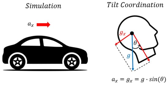
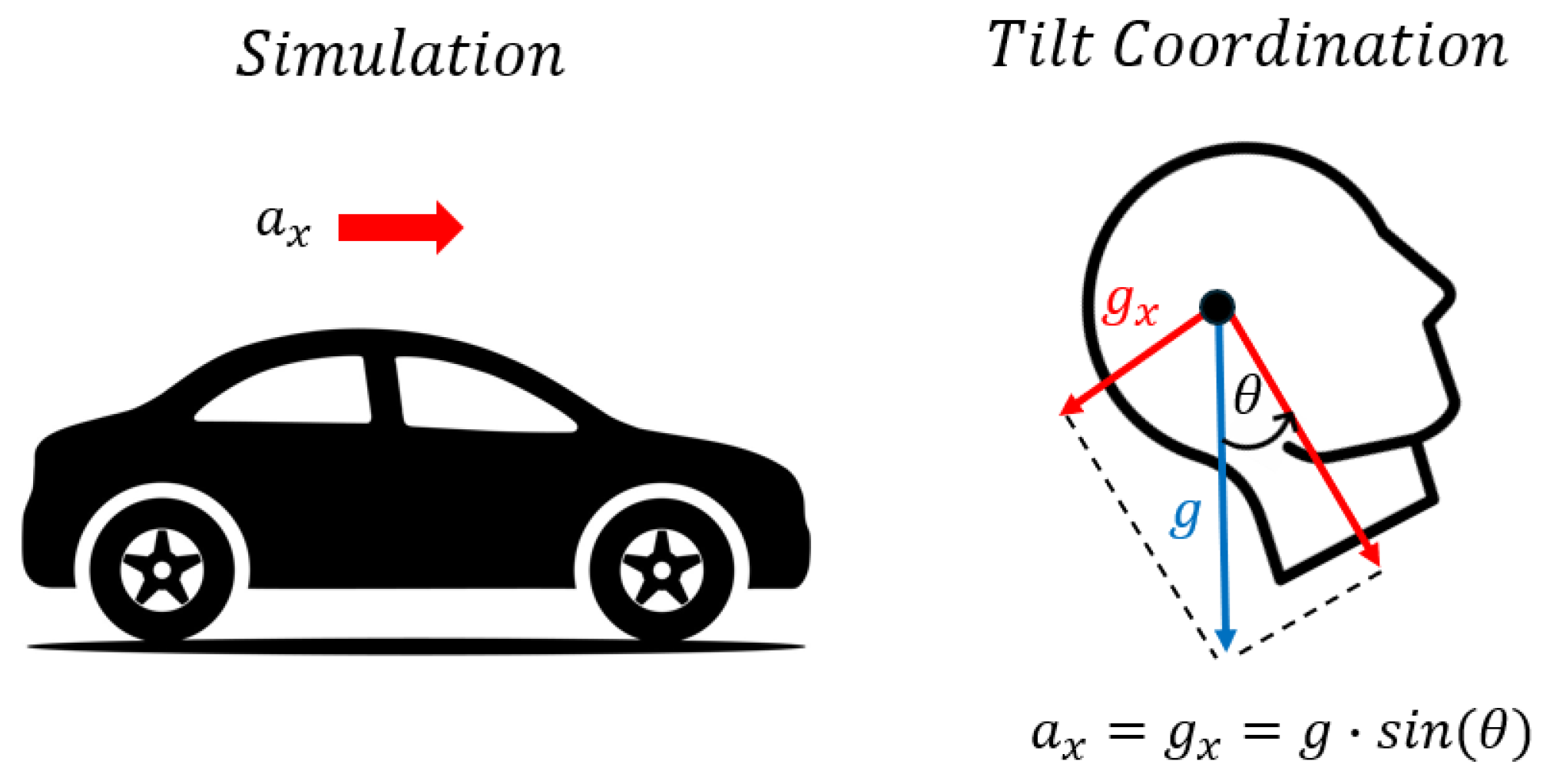
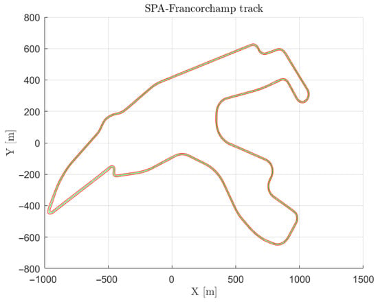
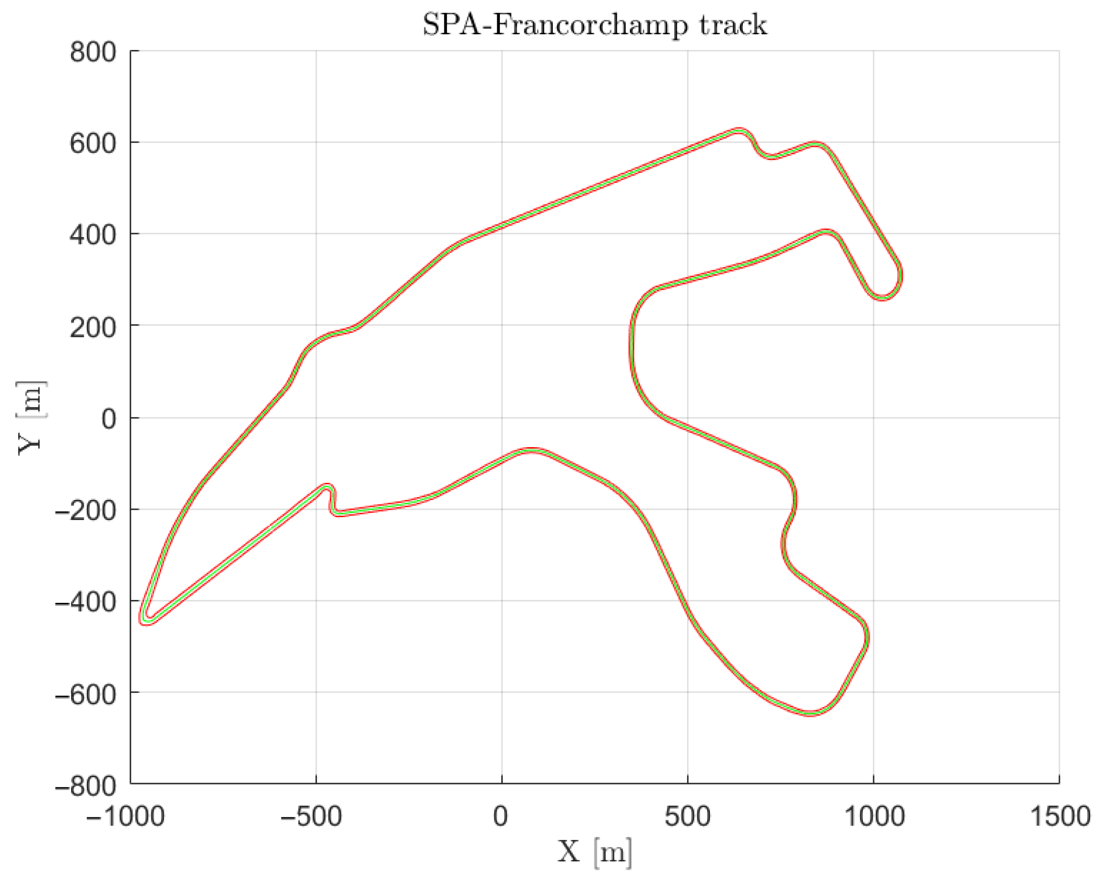
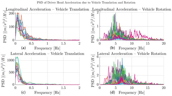
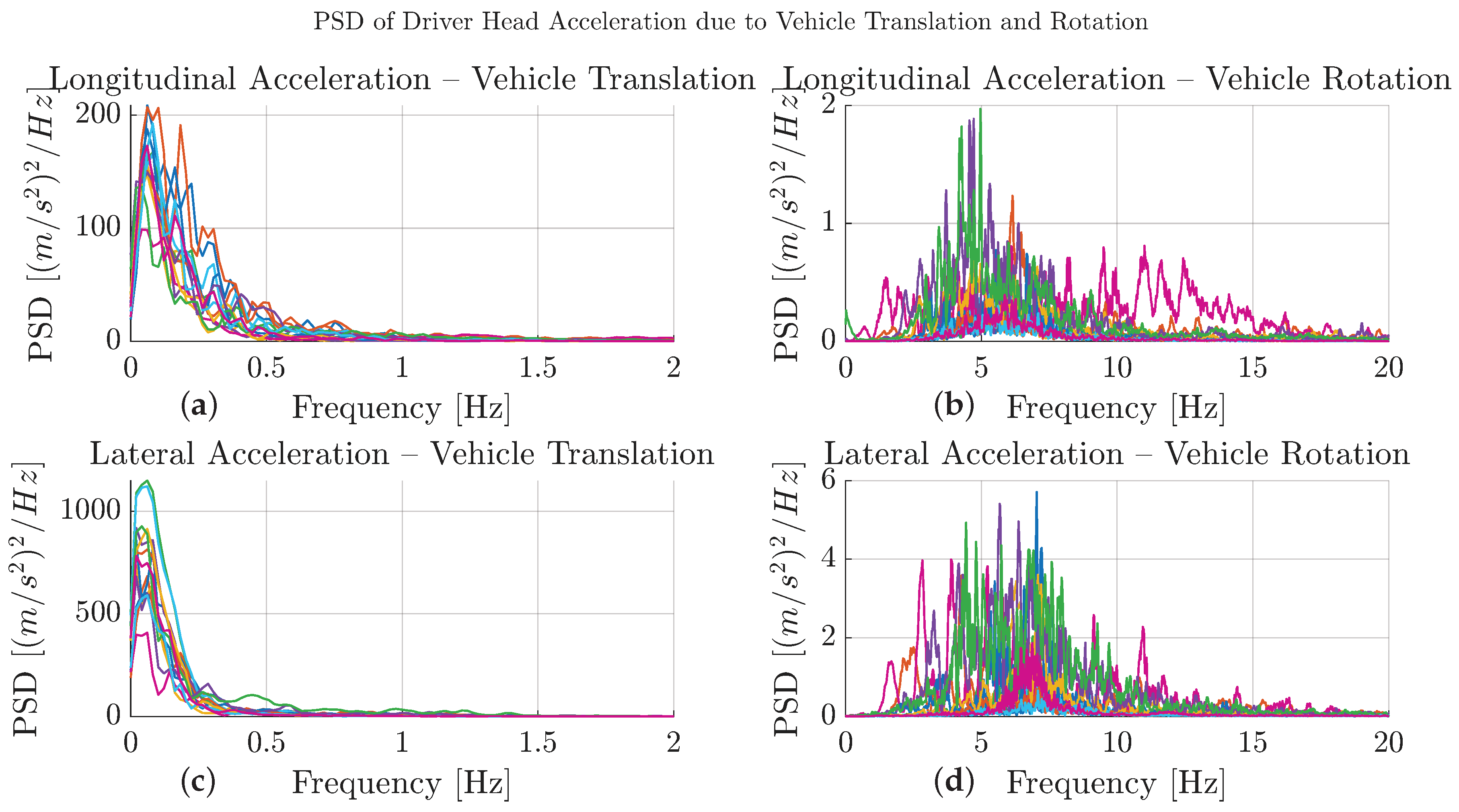
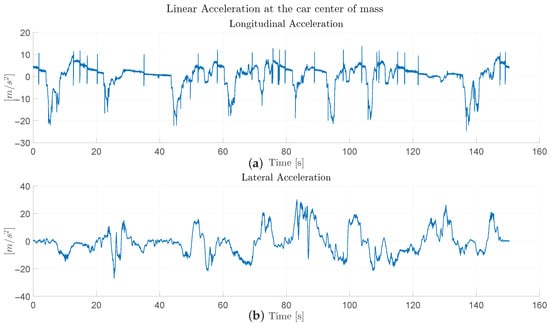
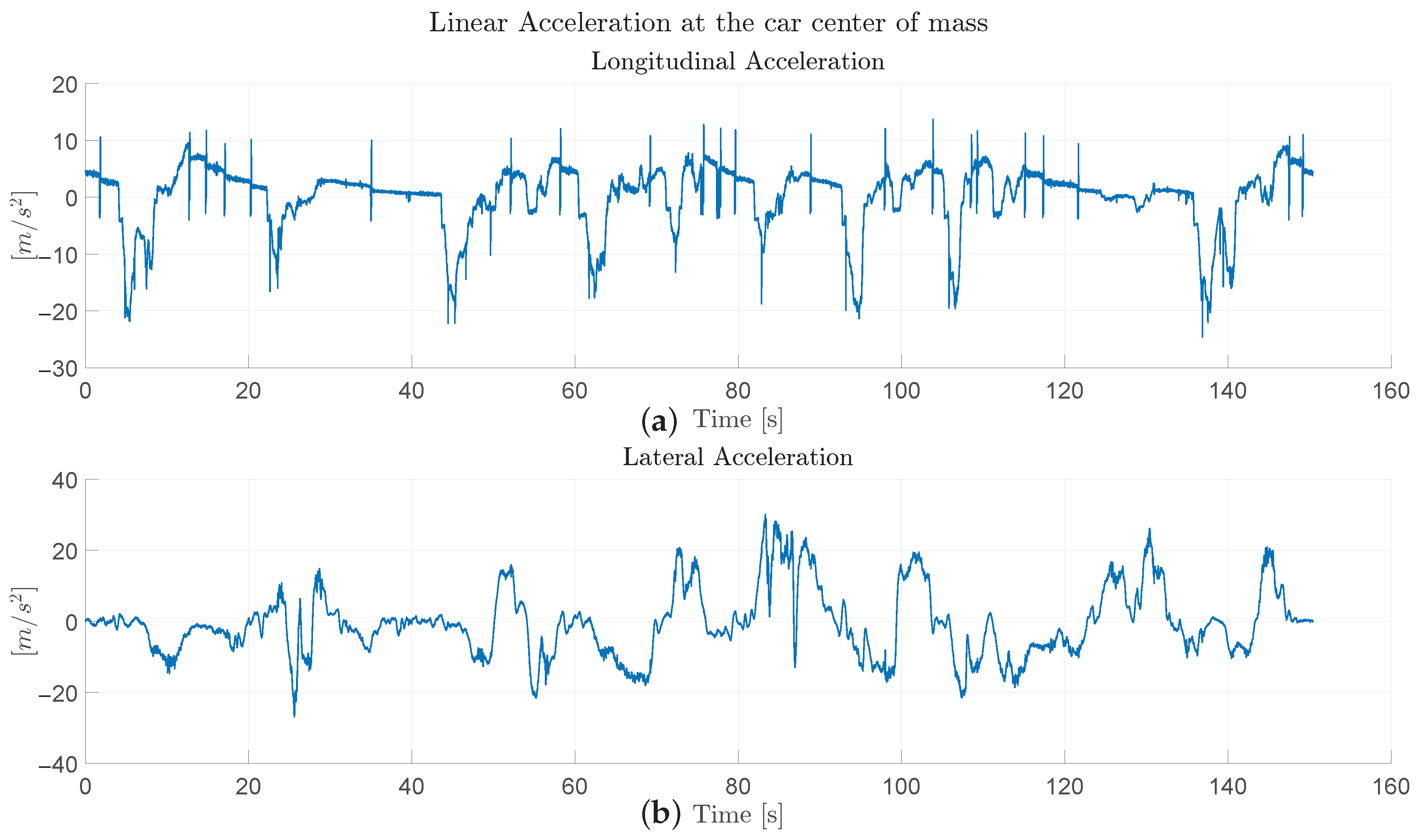


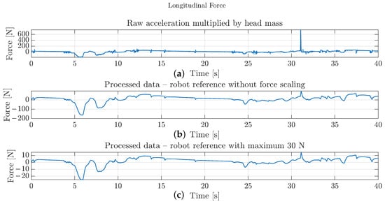
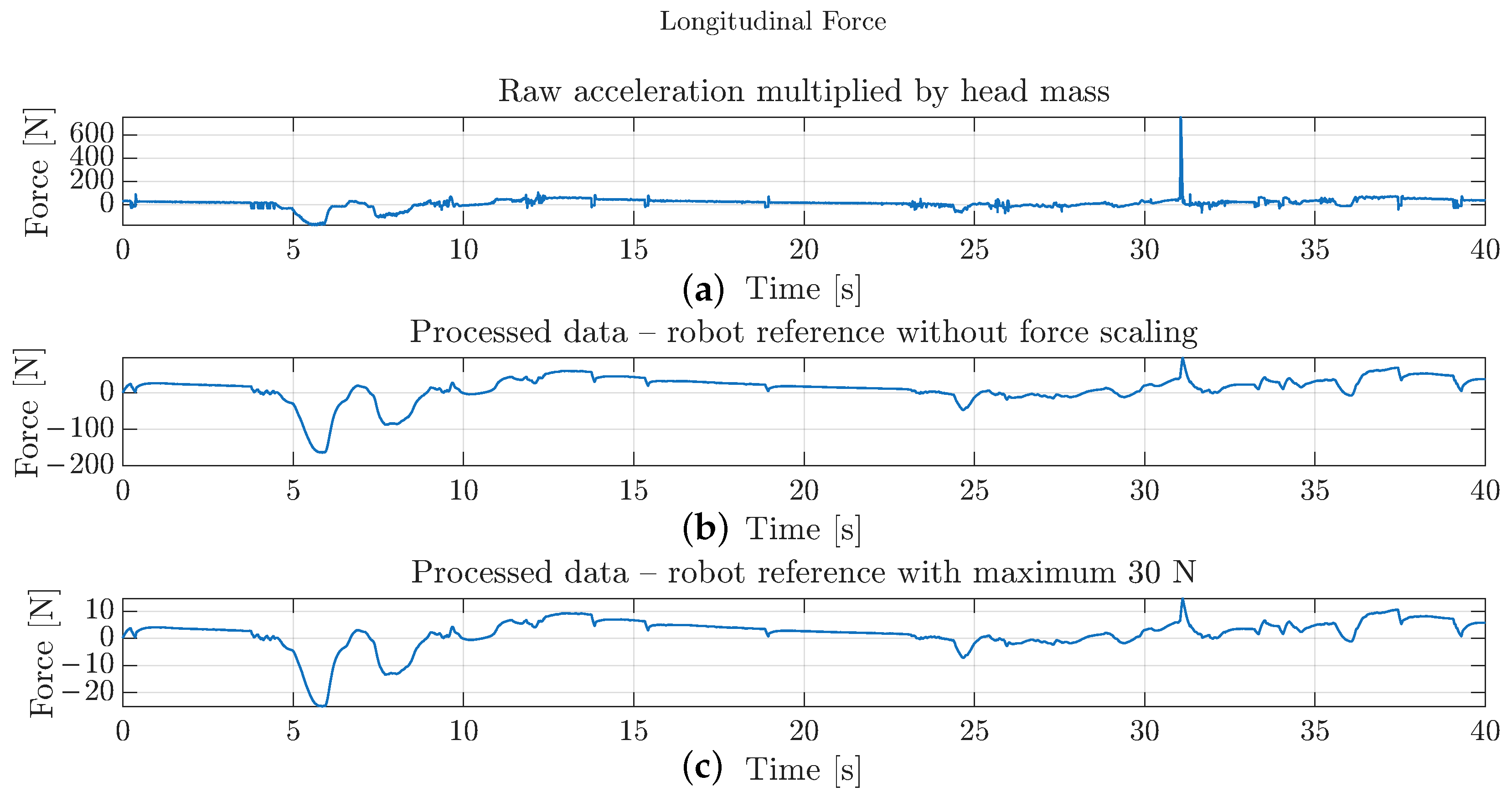
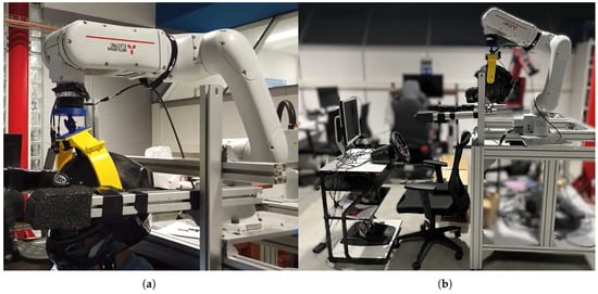
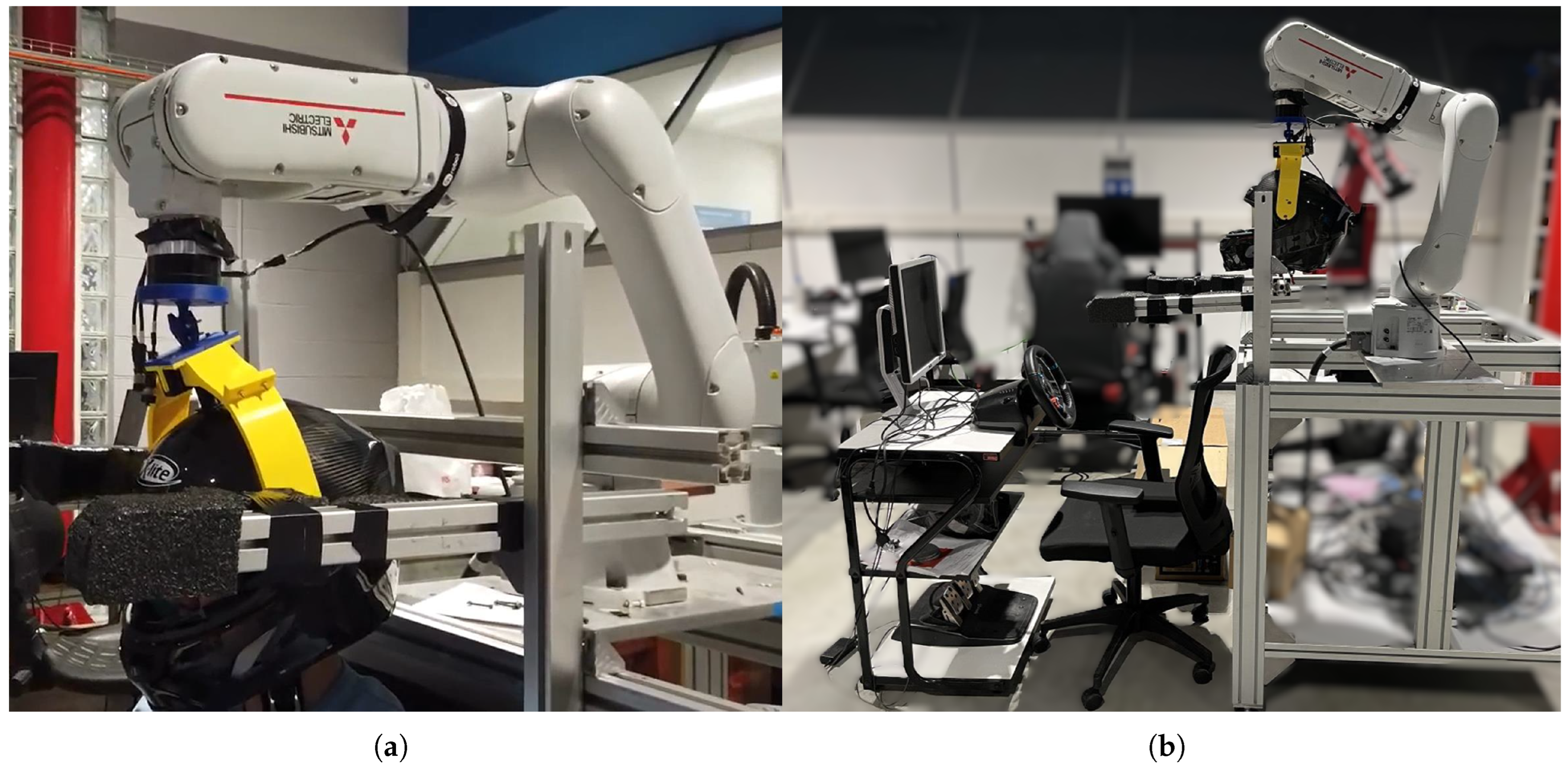
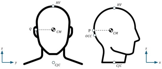
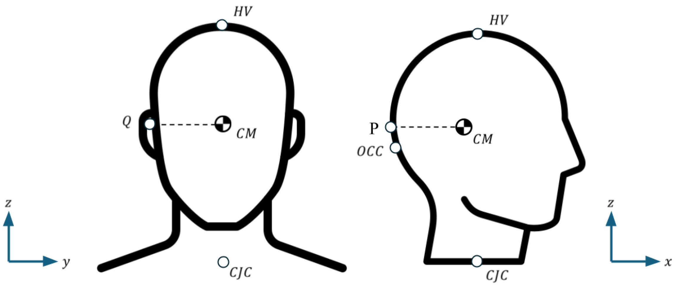
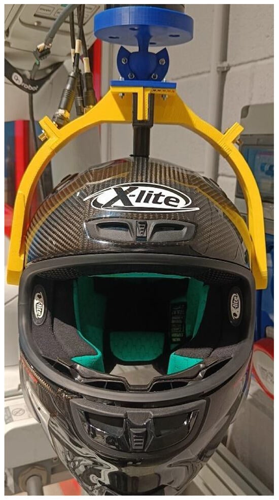
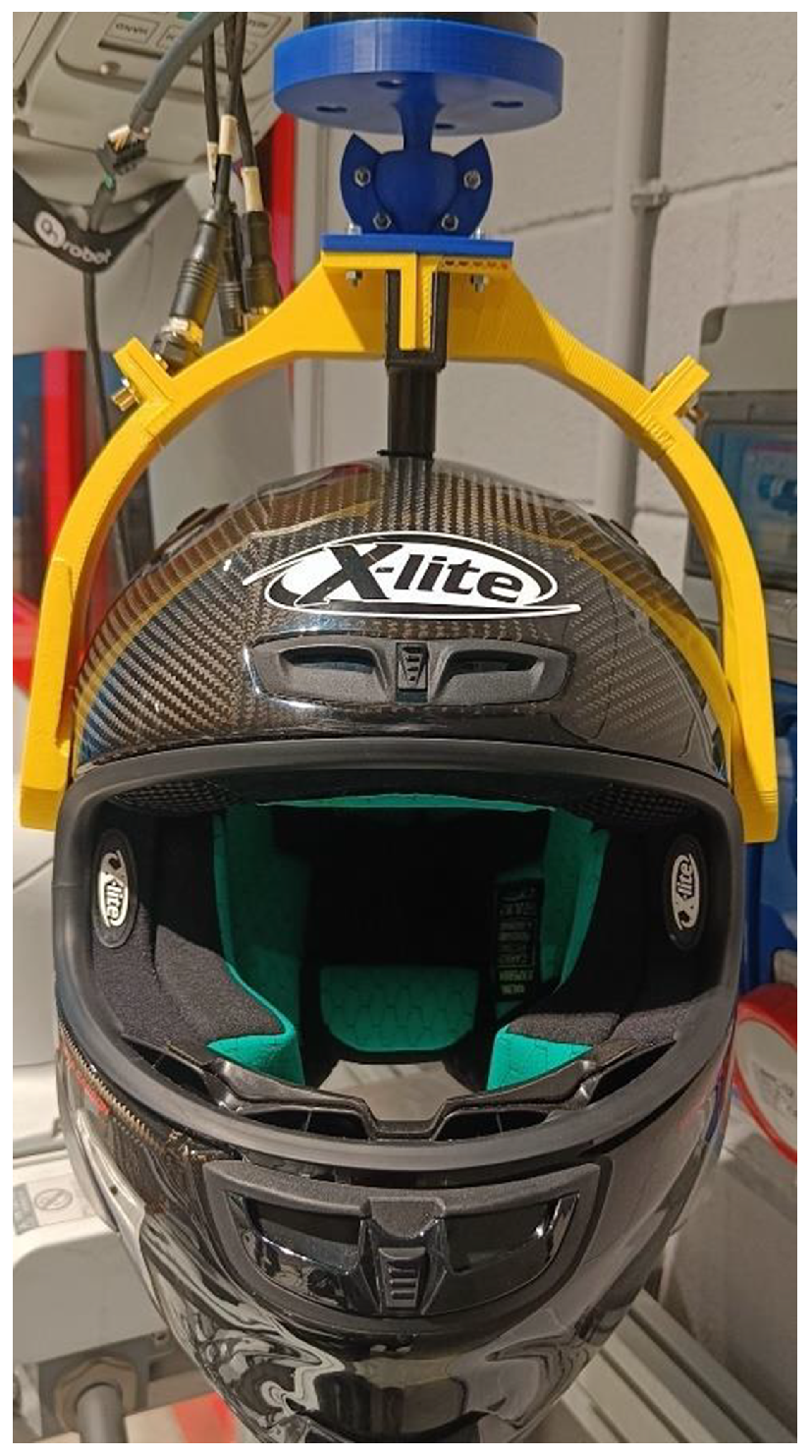
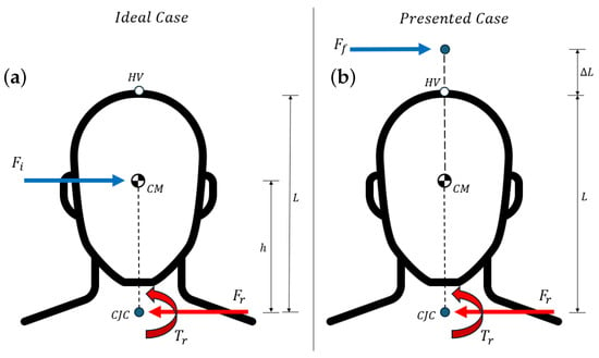
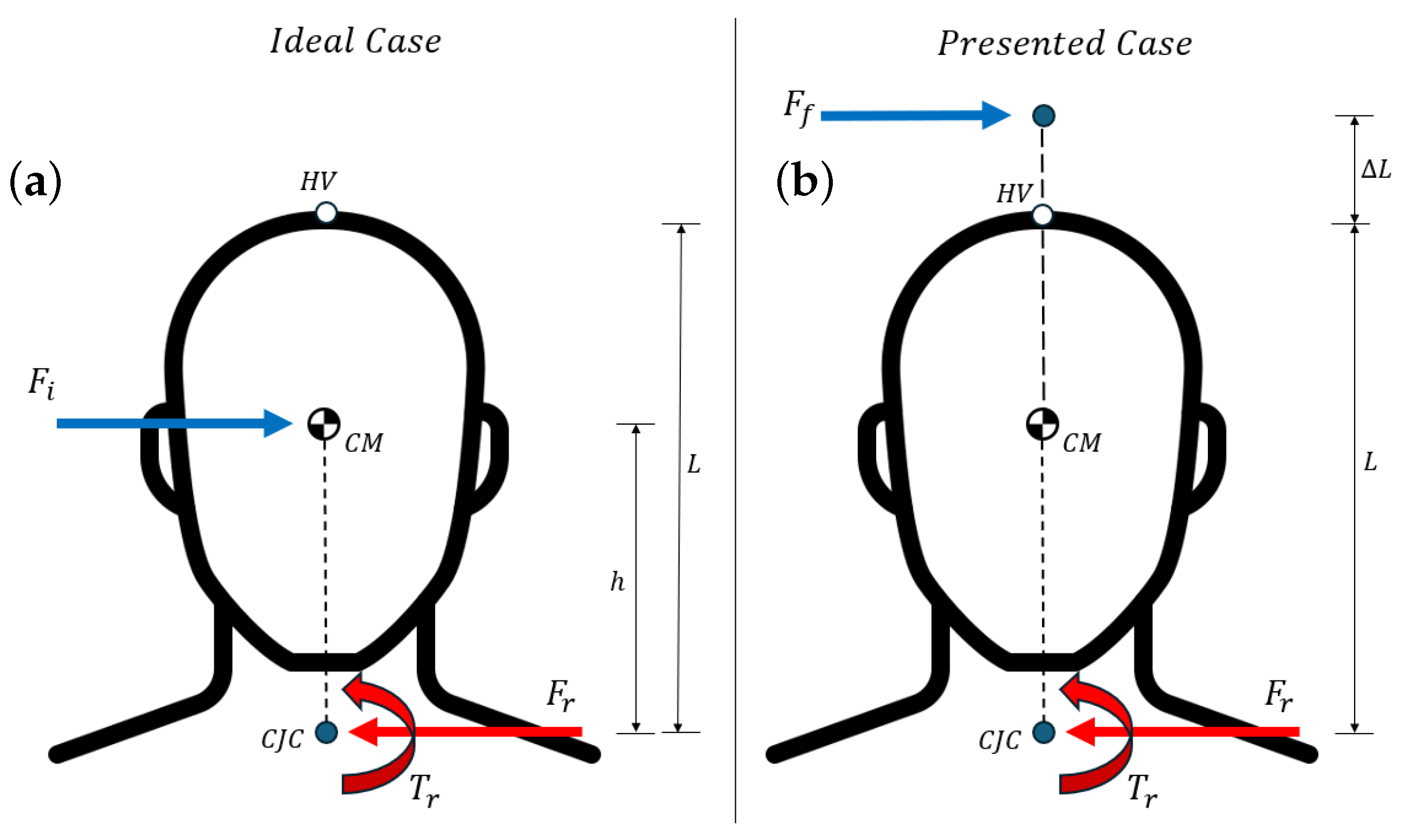
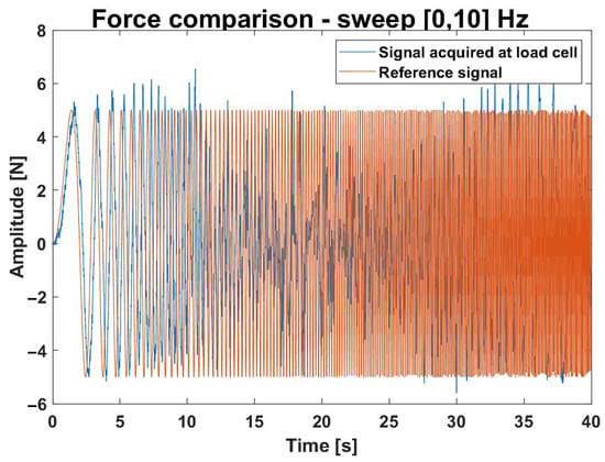
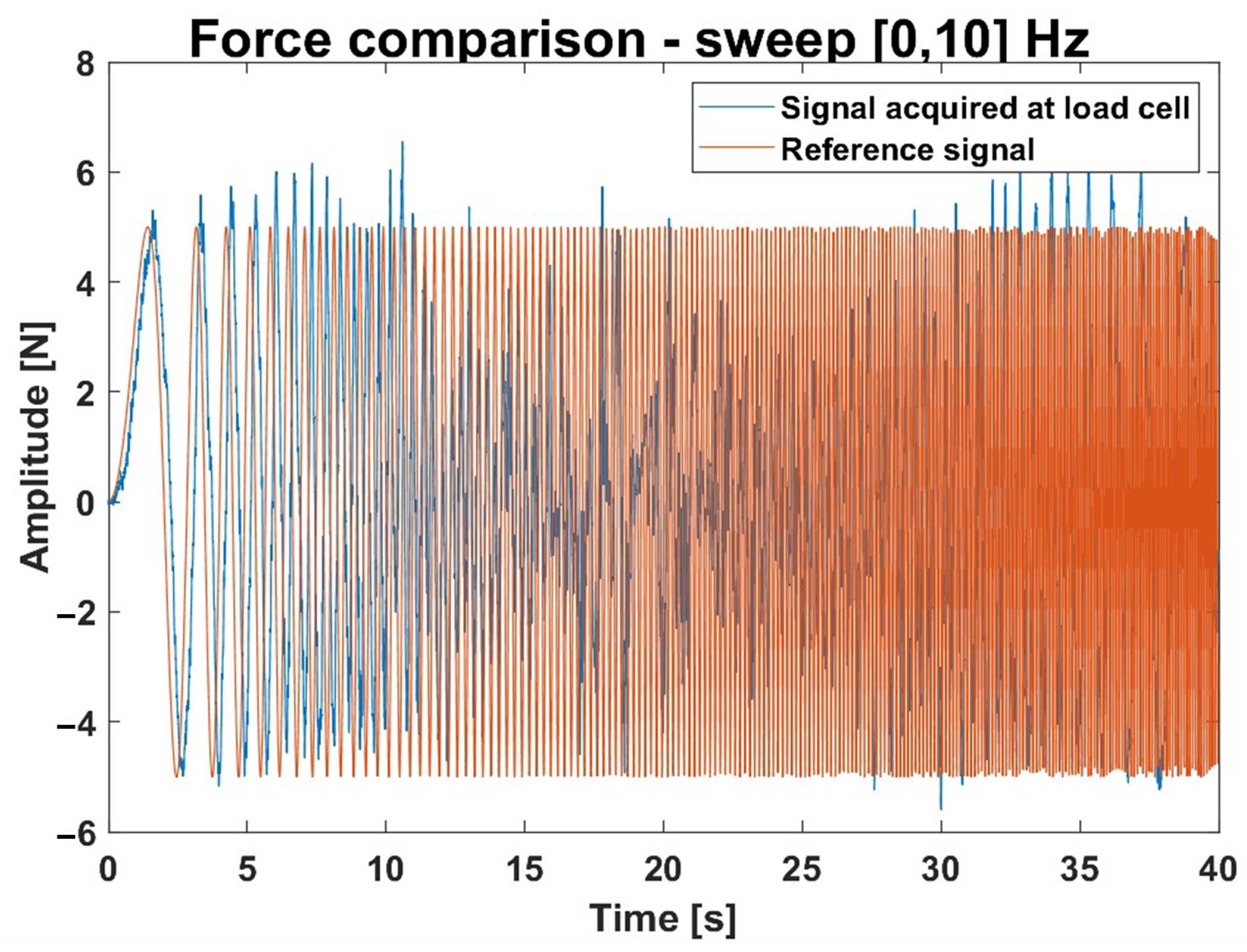
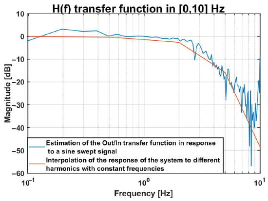
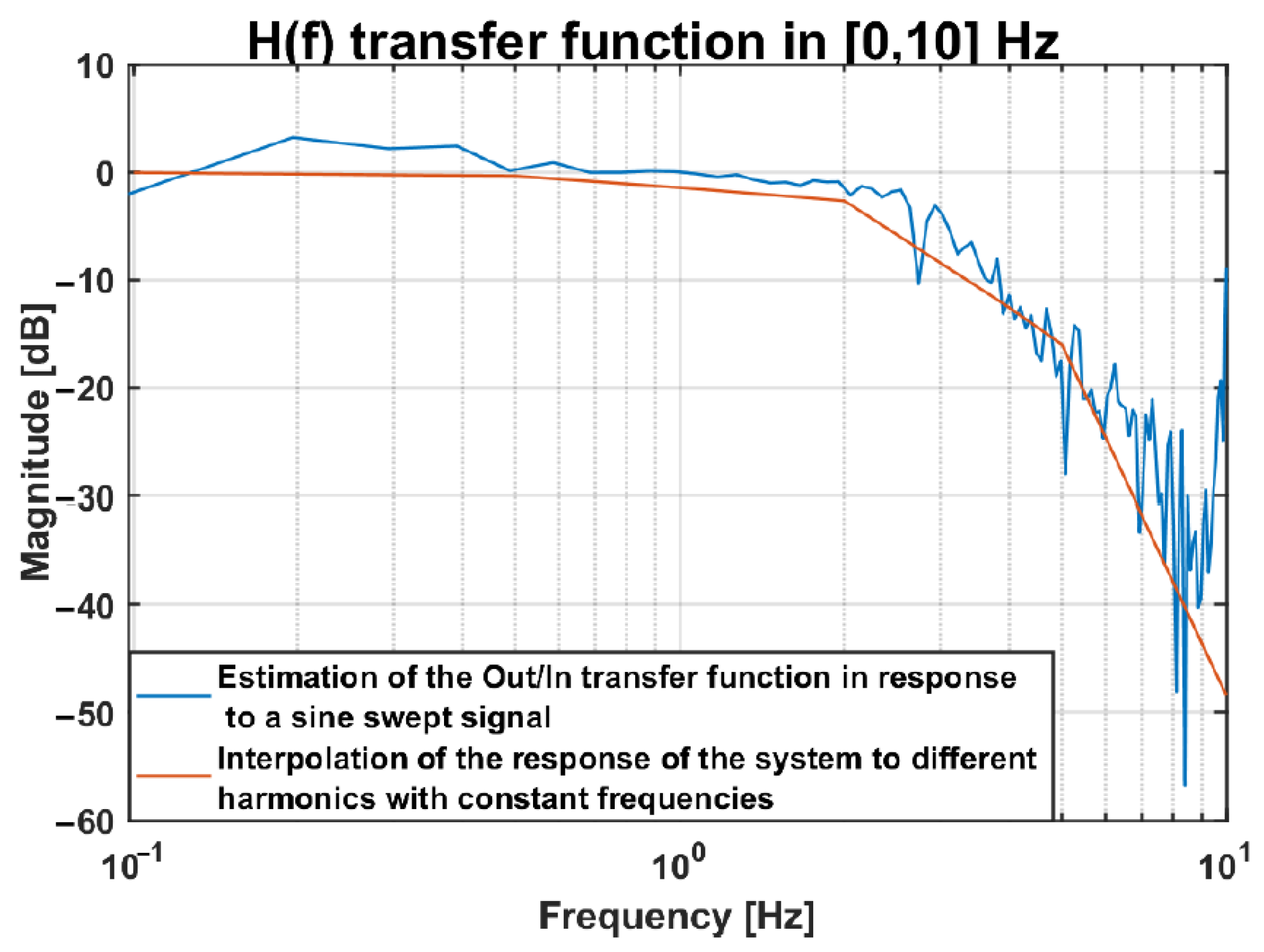
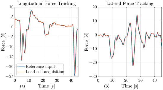
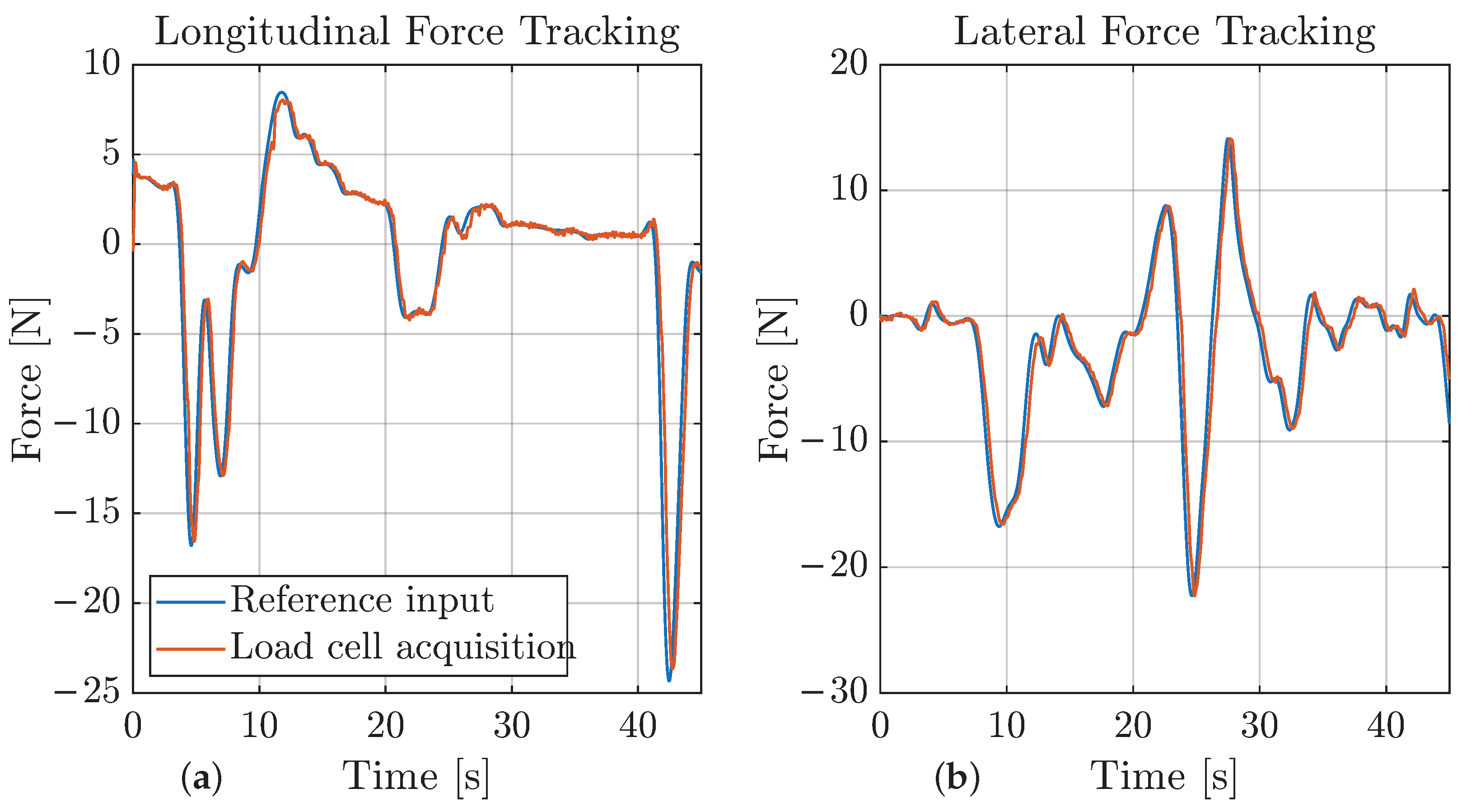
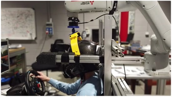
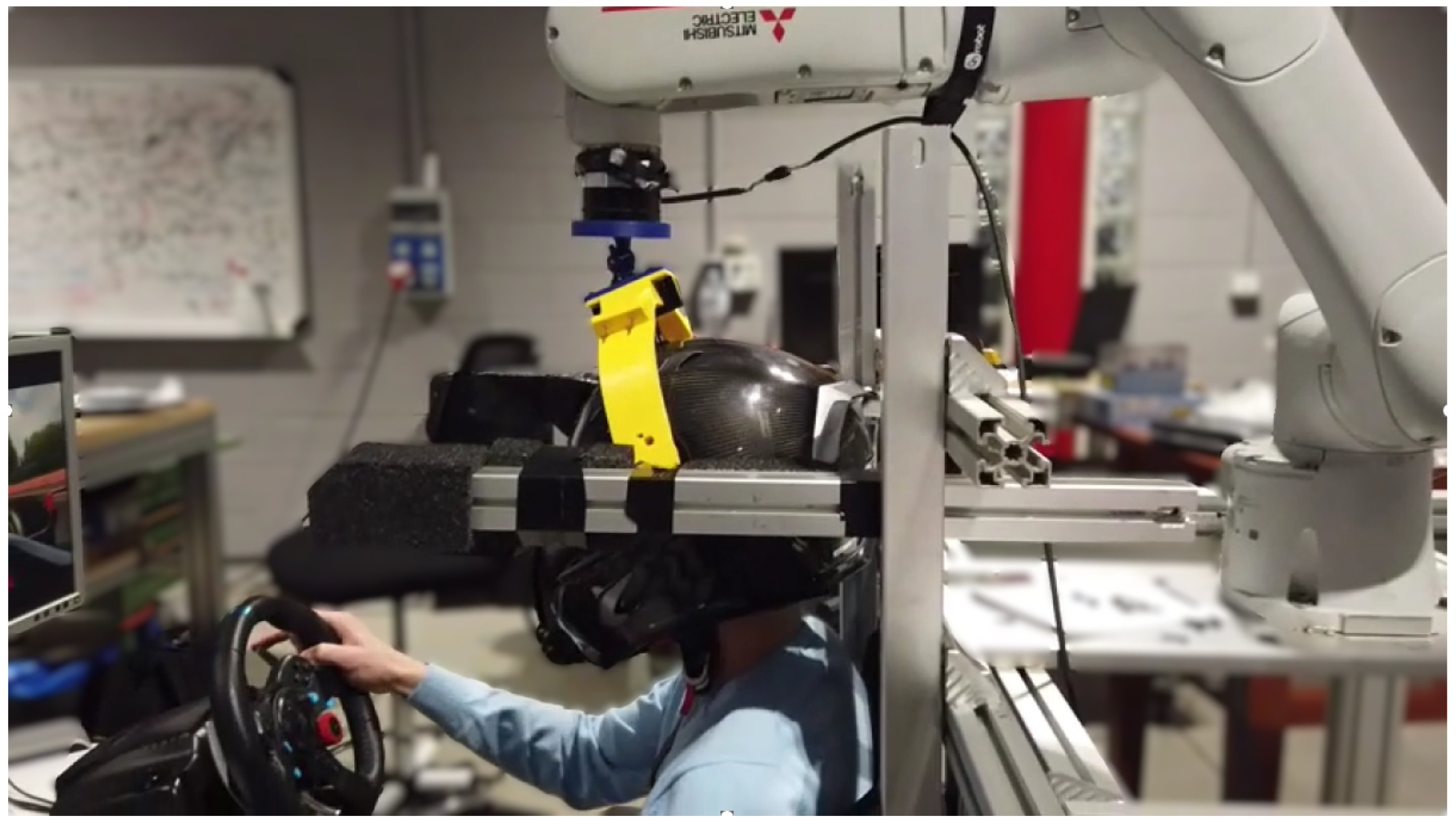
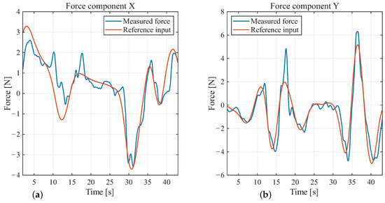
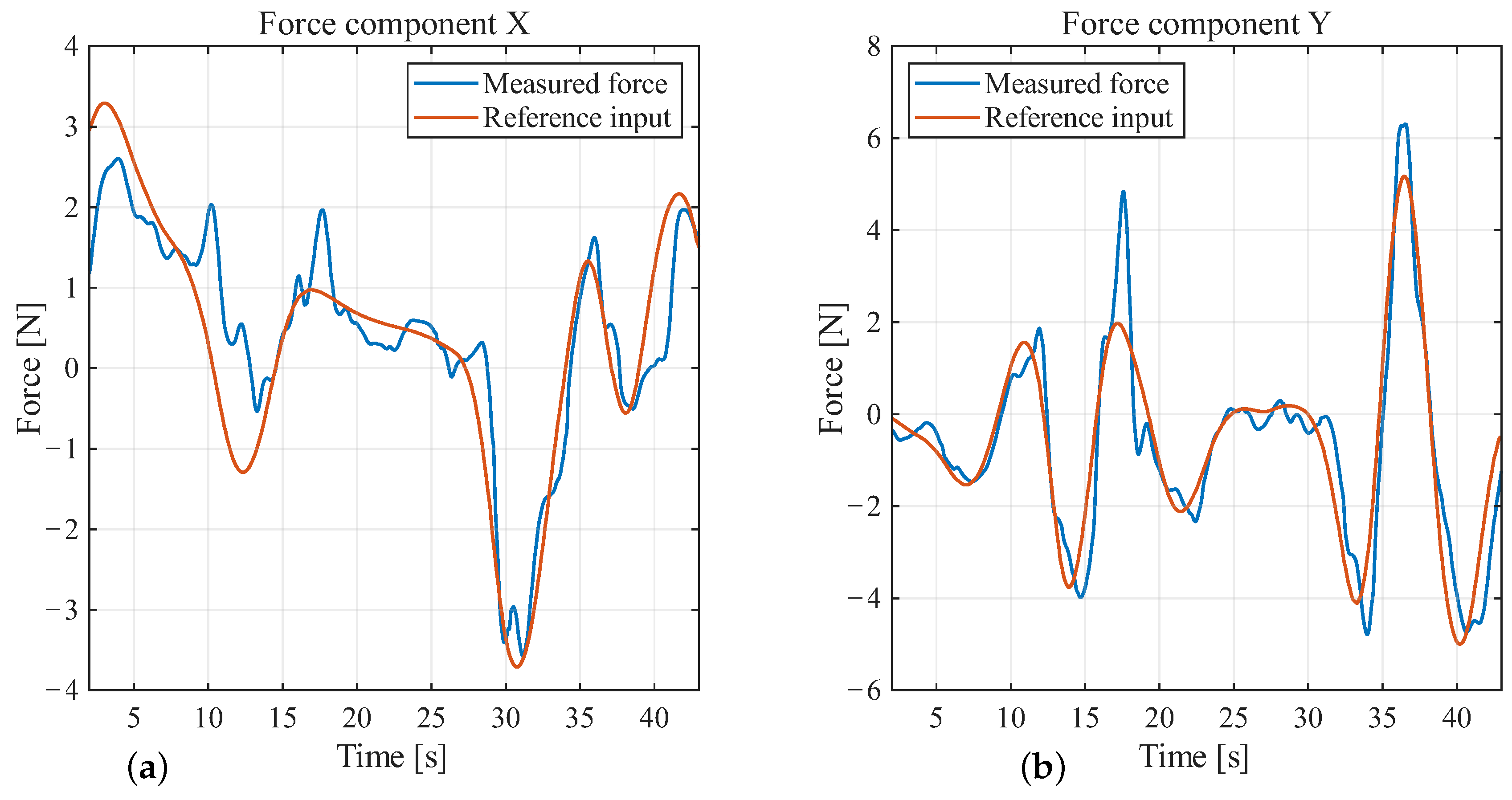
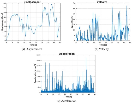
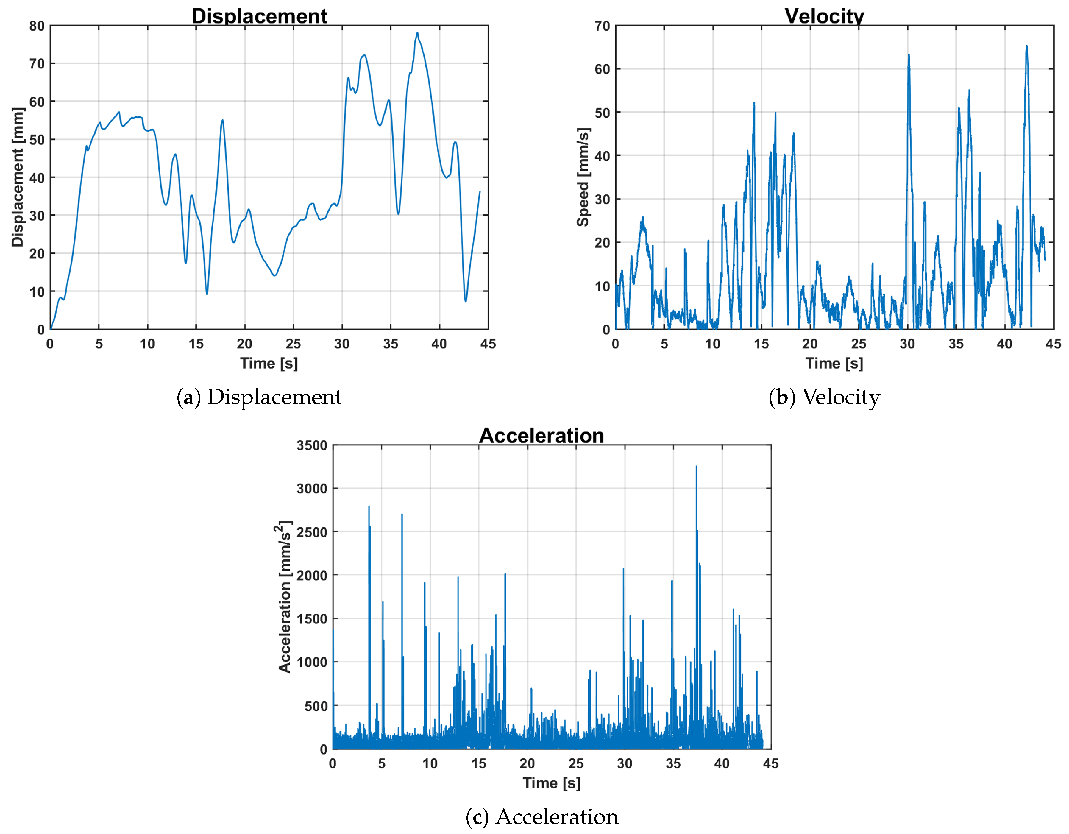

Disclaimer/Publisher’s Note: The statements, opinions and data contained in all publications are solely those of the individual author(s) and contributor(s) and not of MDPI and/or the editor(s). MDPI and/or the editor(s) disclaim responsibility for any injury to people or property resulting from any ideas, methods, instructions or products referred to in the content. |
© 2026 by the authors. Licensee MDPI, Basel, Switzerland. This article is an open access article distributed under the terms and conditions of the Creative Commons Attribution (CC BY) license.