


Abstract
Economic expansion is commonly accompanied by accelerated growth in electricity consumption. In this context, distribution networks play a fundamental role in delivering electricity to end users; however, they remain subject to technical losses. Among system components, power transformers are particularly relevant because, despite their high efficiency, they still generate significant losses due to continuous operation and their widespread presence throughout the electrical system. The literature addresses the relocation of distribution transformers as a strategy to minimize technical losses. However, the application of this approach to equipment installed in electrical substations remains less explored. Therefore, this study proposes an optimization model for reallocating a pool of existing power transformers among electrical substations, matching transformer rated capacities to substation demands to reduce technical losses and enhance energy efficiency. The research methodology involved the mathematical formulation of the problem, adopting the minimization of accumulated total cost as the objective function, which incorporates both technical losses and relocation costs. The model was applied to a case study using technical and operational data from power transformers commonly installed in HV/MV substations. The results demonstrate that the optimal relocation reduced transformer energy losses by approximately 5% over the 10-year planning horizon, generating net economic savings that exceeded the equipment relocation costs. The optimization model suggests adjustments in transformer allocation, aligning loading levels with more appropriate operating ranges and thereby increasing transformer efficiency. Consequently, the proposed approach provides an engineering design-oriented decision-support method for optimizing transformer allocation, contributing to more energy-efficient and economically effective substation planning.
1. Introduction
Electricity demand has been increasing rapidly worldwide, driven by urbanization, industrialization, developments in the transportation sector, and more recently data centers [1]. This growing demand places additional pressure on power systems, making the efficient operation of electricity networks increasingly important. In this context, power grids play a fundamental role in delivering electricity to end users, a process that inevitably involves energy dissipation due to physical laws. This phenomenon is known as technical losses, as it is inherent to system operation [2,3,4].
A representative example can be observed in Brazil. Projections for the 2025–2029 period indicate an average annual Gross Domestic Product (GDP) growth of 2.4%, while electricity load is expected to grow at an average rate of 3.5% per year [5]. According to the Brazilian Electricity Regulatory Agency (ANEEL) [6], technical energy losses in the Brazilian distribution market averaged 7.4% of the total energy input in 2024, corresponding to 44.6 TWh. This volume resulted in an estimated financial impact of USD 2.15 billion. Compared with 2014, the amount of energy lost increased by approximately 20%, highlighting the need for measures to improve the efficiency of distribution systems. To put this in perspective, while European distribution losses ranged from 1.95% to 22.63% in 2022, the most efficient networks demonstrate that losses can be kept near 2% [7].
Of the technical losses in distribution networks, approximately 23% occur in transformers [8], even though these units often exhibit efficiencies exceeding 98%. Despite their high performance, these residual losses represent significant amounts of energy due to continuous operation and their widespread deployment throughout the power system. Reducing losses and improving transformer efficiency can result in substantial energy savings and a reduction in greenhouse gas emissions [9].
Transformer performance is determined by core (no-load) losses, which remain constant whenever the equipment is energized, and copper (load) losses, which vary with the load current [10]. Consequently, transformer efficiency is directly related to its loading level. Operating significantly above or below the rated capacity can increase internal losses and lead to suboptimal performance. Studies indicate that maintaining transformers within an optimal loading range improves efficiency and contributes to reducing energy losses throughout the distribution system [11,12,13].
Given the need for more efficient energy use, transformers have become a focal point in energy efficiency studies because of their direct impact on distribution network performance [14]. In the case of substation transformers, the requirement to handle higher loading levels demands larger physical structures, including higher-volume cores. This characteristic results in considerable internal losses, particularly iron losses. Therefore, ensuring that large-scale transformers operate as close as possible to their maximum efficiency point is essential.
Previous studies have investigated transformer relocation as a strategy to optimize loading conditions and improve the operational efficiency of power systems. In this study, transformer relocation refers specifically to the physical transfer of an existing transformer from one substation to another, without relocating the substation itself or its associated network connections. In [13,15,16], the authors employed mixed-integer linear programming (MILP) models to optimize transformer relocation as a strategy to postpone equipment replacement and improve efficiency while maintaining system reliability. Similarly, in [17], a methodology using a Simulated Annealing algorithm was proposed to reduce technical losses and extend equipment life by strategically repositioning existing medium- and low-voltage (MV/LV) transformers. The financial implications of such movements were further explored in [18], where the NSGA II algorithm was applied to a park of 546 distribution units to balance operational savings with regulatory incentives and efficiency targets.
Beyond purely technical losses, other approaches have focused specifically on mitigating overloads through capacity management. For instance, Ref. [19] utilized a Genetic Algorithm to rotate units of varying sizes (30, 15, and 40 MVA) between feeders to prevent overloading and maximize asset utilization, even accepting minor increases in theoretical power losses as a trade-off for operational safety and better matching unit capacity to feeder demand.
Notably, the existing literature is predominantly focused on MV/LV distribution transformers, whose relocation is generally associated with lower transportation costs, reduced installation complexity, and simpler operational requirements. In contrast, studies addressing the relocation of HV/MV power transformers installed in electrical substations remain limited. These assets differ substantially from distribution transformers in terms of rated power, investment value, no-load losses, transportation requirements, and influence on long-term expansion planning. Consequently, methodologies developed for distribution transformers cannot be directly extrapolated to substation transformers, highlighting the need for dedicated planning tools for this class of equipment.
The relocation of power transformers between substations represents a practical asset management strategy that has been employed by utilities, particularly in developing countries, to improve operational efficiency, optimize the use of existing assets, and postpone costly network expansion projects. Transformer relocation should be regarded as one of several planning alternatives available to distribution utilities. Other strategies, such as transformer replacement, network reinforcement, feeder reconfiguration, or capacity expansion, may also be adopted depending on system requirements and long-term planning objectives. However, when suitable transformers are already available within the existing asset inventory, relocation offers a cost-effective alternative that improves asset utilization while postponing more expensive infrastructure investments. Recent advances in utility digitalization and asset management systems have further increased the practical feasibility of applying optimization techniques to support this planning strategy.
In this context, this study proposes an optimization model for the relocation of HV/MV power transformers among electrical substations. Although the optimization problem is formulated as a classical assignment model, its contribution lies in addressing a planning problem that has received limited attention in the literature, namely the relocation of HV/MV substation transformers. Unlike previous studies focused primarily on MV/LV distribution transformers, the proposed model integrates long-term energy loss estimation, projected demand growth, electricity price evolution, and transformer relocation costs within a unified planning framework. In addition, the methodology enables the assessment of the operational and regulatory impacts of different transformer allocation strategies. From an engineering design perspective, the proposed methodology supports the configuration of transformer allocation within the existing substation infrastructure by systematically evaluating alternative equipment arrangements under technical and economic constraints.
As an optimization-based engineering design method, the proposed model aims to support utility decision-making by improving energy efficiency while simultaneously considering technical, economic, and planning aspects. The adopted mixed-integer linear programming formulation is particularly suitable for this application because the objective function and technical constraints can be represented linearly, allowing the global optimum to be obtained efficiently through an exact optimization method. Unlike heuristic approaches, the proposed formulation provides deterministic solutions with guaranteed optimality for the formulated planning problem.
The remainder of this paper is organized as follows. Section 2 presents the proposed optimization model, including the mathematical formulation of the objective function and its constraints. Section 3 presents and discusses the results obtained from the optimization process. Finally, Section 4 summarizes the main conclusions and outlines directions for future research.
2. Methodology
The proposed methodology consists of an optimization algorithm for power transformer relocation. The model adopts the existing configuration as the baseline scenario, in which the units are already operating in their respective substations. The analysis evaluates the relocation of at least one pair of transformers to identify an improved configuration that minimizes the total accumulated cost. This cost includes technical energy losses over the analysis period as well as the costs associated with equipment relocation between substations.
The study was structured into four main stages: mathematical formulation of the problem, including the definition of the objective function and constraints (Section 2.1); computational implementation of the optimization model (Section 2.2); characterization of the technical and operational data of the transformers used in the case study (Section 2.3); and testing and validation procedures based on predefined performance criteria (Section 2.4).
2.1. Optimization Model
The problem formulation aims to determine the optimal allocation of transformers among substations to minimize the costs associated with technical losses over the analysis period and equipment relocation costs, as defined in Equation (1). Accordingly, the model seeks an arrangement that results in the lowest possible total cost, ensuring an economically efficient solution.
where
| Set of power transformers | |
| Set of possible allocation positions (substations) | |
| Accumulated cost of technical losses associated with the operation of transformer at position over the analysis period | |
| Cost of relocating transformer from its initial position to position | |
| Binary decision variable equal to 1 if transformer is assigned to position and 0 otherwise |
Equation (2) expresses the cost of electrical losses resulting from the operation of each transformer allocated to a given substation position. The cost is calculated on an annual basis, considering projected load growth and tariff adjustments over the analysis period.
where
| Analysis period (years) | |
| Rated no-load (core) losses of transformer (kW) | |
| Rated load (copper) losses of transformer (kW) | |
| Projected peak demand at substation position in year adjusted by the load growth factor α (MVA) | |
| Rated power capacity of transformer (MVA) | |
| Loss factor | |
| Number of hours per year | |
| Electricity cost in year obtained by adjusting the base cost () according to the variation in the inflation index |
The loss factor is estimated using Equation (3):
where
| Empirical load correlation coefficient (adopted as 0.3 [20]); a sensitivity analysis is provided in Appendix A | |
| Projected average demand at substation position in year adjusted by the load growth factor α (MVA) |
The decision to reallocate a power transformer involves not only reducing technical losses but also evaluating the operational and logistical costs associated with equipment relocation, which can be significant. Even when a new allocation reduces energy loss costs, the resulting economic benefit may not be sufficient to justify the relocation process. Therefore, the optimization model must incorporate the physical relocation costs of transformers between substations, typically including dismantling, transportation, and reinstallation costs, as presented in Equation (4). The relocation cost includes all activities required to transfer a transformer between substations, including equipment removal, transportation, reinstallation, civil adaptations, electrical integration activities, commissioning procedures, and other infrastructure adjustments required to accommodate the transformer at the destination substation. When a transformer remains assigned to its original substation position, the corresponding relocation cost is assumed to be zero. Therefore, relocation costs are incurred only when the assigned destination differs from the transformer’s original location.
where
| Fixed cost associated with transformer dismantling and reinstallation | |
| Distance between the origin substation and the destination substation for transformer (km) | |
| Variable transportation cost per kilometer |
To ensure the technical feasibility of the proposed solution, the model incorporates a set of constraints that define the feasible region. Equations (5)–(8) formalize these constraints.
- (a)
- Each allocation position in a substation must receive exactly one transformer—Equation (5):
- (b)
- Each transformer may be allocated to at most one substation position—Equation (6):
- (c)
- The transformer must be capable of meeting the projected peak demand, considering the load growth factor—Equation (7):
The capacity constraint is evaluated for every year of the planning horizon using the projected peak demand corresponding to each year. Therefore, all feasible solutions satisfy the transformer capacity requirement throughout the entire analysis period.
- (d)
- The transformer’s primary and secondary voltage ratings must be compatible with those of the assigned substation position—Equation (8):
The compatibility criteria adopted in this study are intended to support the stage of transformer relocation. Although additional engineering aspects, such as vector group, impedance characteristics, cooling system, protection requirements, and installation-specific constraints, should be verified prior to field implementation, Brazilian electric utilities commonly adopt standardized specifications for HV/MV power transformers. This standardization reduces the variability of equipment installed in the network and makes rated capacity and voltage compatibility appropriate first-level criteria for planning-oriented optimization models.
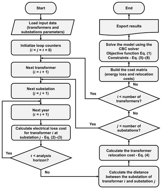
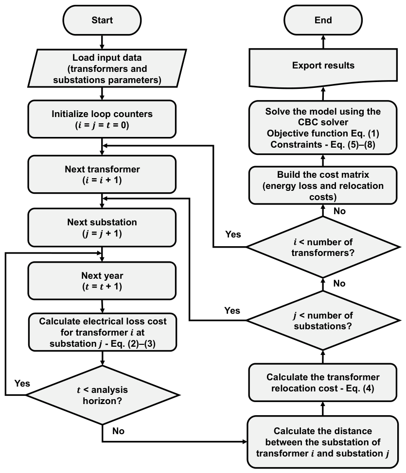
The flowchart shown in Figure 1 summarizes the steps of the process.
Figure 1.
Schematic flowchart of the proposed optimization process.
2.2. Computational Aspects
The optimization model was implemented in Python 3.8.3 using the PuLP library to define the objective function, decision variables, and problem constraints. The optimal solution was obtained using the COIN-OR Branch and Cut (CBC) solver, which solves mixed-integer programming problems through a tree-search procedure combined with cutting planes. This approach reduces the feasible solution space and ensures efficient convergence [21]. Data related to the characteristics of substations and transformers were organized in spreadsheets, allowing direct import into the computational model and facilitating updates to the input parameters.
The optimization model comprised 2401 binary decision variables and 1798 constraints. The optimal solution was obtained in approximately 0.05 s (0% optimality gap) on a computer equipped with an Intel® Core™ i5-2450M processor (2.50 GHz), 6 GB of RAM, and a 64-bit operating system. Although a formal scalability analysis was not performed, the observed computational performance indicates that the proposed model is computationally efficient for practical planning applications. Considering that even large electric distribution utilities typically operate on the order of hundreds to approximately one thousand HV/MV power transformers, the expected problem size remains well within the capabilities of modern mixed-integer optimization solvers.
2.3. Case Study: Technical and Operational Transformer Data
Transformers installed in high-voltage/medium-voltage (HV/MV) distribution substations typically operate with primary voltages of 34.5 kV, 69 kV, or 138 kV, stepping them down to the primary distribution level of 13.8 kV. Common voltage ratios include 138/13.8 kV and 69/13.8 kV. The rated power of these transformers varies according to the demand characteristics of the served area. For example, 10 MVA transformers are commonly used in regions with lower load density [22,23].
The transformer sample considered in this study comprises units operating at voltage ratings of 69/13.8 kV and 138/13.8 kV, with different rated power levels commonly employed in distribution systems. Table 1 presents the technical specifications, including nominal no-load and load losses, based on data obtained from manufacturers datasheets. These values are essential for assessing the impacts associated with electrical energy losses.
The geographic coordinates of the substations were extracted from the utility’s Geographic Database [24], serving as the spatial reference for the sample considered in this study. This georeferenced information is essential for the accuracy of the proposed model, as it enables the calculation of the distances used to estimate transformer relocation costs. The transformer ratings, loading levels, voltage classes, and substation characteristics adopted in this case study were defined based on values commonly found in electrical distribution utilities.
To preserve the confidentiality of utility operational data, the case study was not constructed from the operational database of a specific distribution company. Instead, a representative dataset was assembled by combining publicly available geographic information, manufacturers’ technical specifications, and operating conditions commonly observed in Brazilian HV/MV distribution systems. This approach preserves the realism and practical relevance of the case study while avoiding the disclosure of confidential utility operational data.
Table 1.
Technical specifications of the power transformers. Source: WEG [25].
The sample considered in this study comprises 49 transformers, limited to the specifications presented in Table 1 and distributed across 35 substations. Some of these substations contain more than one transformer. Among the analyzed units, 32 operate at a voltage ratio of 138/13.8 kV and 17 operate at a voltage ratio of 69/13.8 kV. The allocation of transformers per substation and the operational data used in the analysis, including average demand, peak demand, and efficiency, are presented in Appendix B. These data were defined to represent typical characteristics and operating conditions of a distribution system.
2.4. Testing and Validation
Model performance was evaluated by comparing two scenarios. The first represents the current configuration, in which the original transformer allocation is maintained as the baseline. The second corresponds to the proposed optimization, where the model reallocates equipment while considering technical losses and relocation costs. The comparison included technical losses, associated costs, operational parameters, and the Substation Utilization Index (SUI), enabling an assessment of installed capacity utilization in accordance with regulatory standards.
SUI represents the percentage of installed capacity effectively used, indicating the extent to which the asset is serving the distribution system [26]. Consequently, the value recognized in the electricity tariff to remunerate the company’s investments considers not only the amount invested in assets, such as substations, but also the actual level of utilization of these facilities. Therefore, SUI is applied as a regulatory indicator to support planning and decision-making by distribution companies, enabling the assessment of whether investments in upgrades or capacity expansions contribute to improved utilization of installed capacity. Equation (9) presents the calculation of the SUI considering projected demand growth over a 10-year horizon.
where
| Maximum load of the substation (MVA) | |
| 10-year load growth expectation | |
| Total installed capacity of transformers in a substation (MVA). |
The 10-year load growth expectation is given by Equation (10):
where
| Annual growth rate in year (%) |
Internal energy losses in transformers were calculated based on a 10-year planning horizon, in accordance with the Brazilian regulatory guidelines established in Module 2 of the Distribution Procedures of the National Electric Power System [27]. A load growth rate of 3.5% per year was considered over this period [5]. For the economic valuation of these losses, an estimated electricity cost of US$0.052 per kWh [28] was applied, enabling the calculation of the total accumulated losses over the analysis period. This value was updated annually based on the average inflation rate observed over the last ten years, estimated at approximately 7% per year.
Considering that the costs associated with transformer relocation—including dismantling, transportation, and reinstallation—may vary significantly depending on equipment size and operational conditions, a sensitivity analysis was conducted. The relocation cost was varied over a representative range to assess its impact on reallocation decisions. This approach enables the identification of cost intervals in which transformer relocation is economically advantageous, as well as thresholds beyond which relocation becomes economically infeasible as costs increase.
3. Results and Discussion
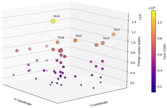
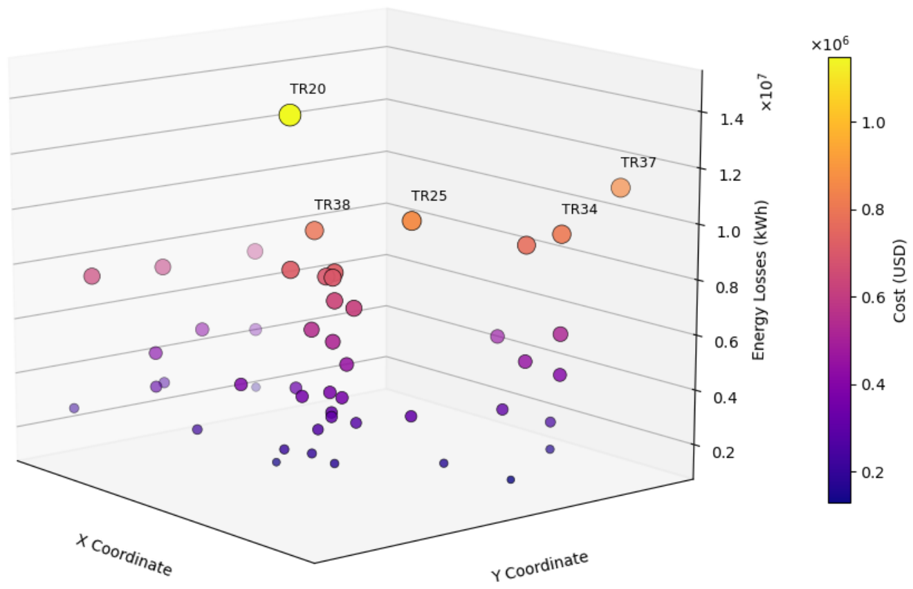
The current transformer configuration results in approximately 277 GWh of energy losses over the ten-year planning horizon, leading to a cumulative cost exceeding US$21.9 million. Figure 2 illustrates the spatial distribution of the substations and their installed transformers in the horizontal plane, while the vertical axis represents the total energy losses accumulated by each unit over the analyzed period. The color scale denotes the monetary cost associated with these losses, incorporating the electricity purchase price and projected annual tariff adjustments.
Figure 2.
Energy losses and associated monetary costs for the current transformer allocation configuration by substation.
The five transformers with the highest losses are explicitly identified in Figure 2, namely TR20, TR37, TR25, TR34, and TR38. Together, they account for approximately 20% of the total losses, corresponding to nearly 56 GWh of energy losses and a total cost of US$4.5 million. Table 2 complements Figure 2 by detailing the energy losses and corresponding costs for the five substations with the highest losses, as well as their utilization factors () in the base year and after ten years, considering load growth. A significant share of these losses is directly associated with operation at high utilization factors, deviating from the maximum efficiency point. Furthermore, in some cases, transformer loading is projected to exceed the nominal capacity by the end of the analysis period. This behavior indicates that, from a long-term planning perspective, equipment replacement will be required within a shorter time frame than that adopted in this study, regardless of the relocation recommendations provided by the optimization model.
Table 2.
Operational characteristics of the top five electrical substations with the highest energy losses.
Since the fixed and variable costs associated with transformer relocation—corresponding to the parameters of Equation (4)—may vary according to operational, logistical, and contractual conditions, the optimization model developed in this study was solved under different combinations of these values. This approach enabled the assessment of how distinct cost scenarios affect the behavior of the objective function defined in Equation (1). The results are presented in Table 3 and correspond to the optimized total cost, defined as the sum of the accumulated energy loss cost and the transformer relocation cost.
Table 3.
Optimized total cost (US$ million) for different fixed and variable cost scenarios.
The minimum fixed cost adopted was US$38,462, based on a reference value reported for the installation of a power transformer only [29]. Since this amount does not encompass the full relocation cost—excluding procedures such as transformer removal—it was used as a baseline for successive increments of US$19,231. For the variable cost, a minimum value of US$19 per kilometer was adopted, representing transportation expenses [30]. From this baseline, additional scenarios were generated with increments of US$19/km, allowing the evaluation of the impact of these variations on the optimal solution of the model.
Notably, all optimized total cost scenarios presented in Table 3 resulted in values lower than the US$21.9 million total cost of the original transformer configuration. For clarity and detailed reporting, the results for the optimized scenario adopting a fixed cost of US$76,923 and a variable cost of US$58 per kilometer are selected for further analysis. This specific case serves as a reference to more clearly demonstrate the model’s functionality and facilitate the interpretation of the resulting data.
In the selected optimized scenario, total energy losses reached approximately 263 GWh over the analyzed horizon, corresponding to an estimated cost of US$20.6 million. Compared with the current configuration, this new equipment layout provides a reduction of about 5% in energy losses, representing avoided transformer loss costs of approximately US$1.15 million. To achieve this performance, the model implemented nine transformer relocations between substations, resulting in a total relocation cost of US$0.74 million. Consequently, the optimized configuration yields net savings exceeding US$0.41 million. Table 4 presents a comparison of the 10-year projected total loss costs between the current configuration (Scenario 1) and the optimized scenario (Scenario 2), detailing the economic benefits from loss reduction and the associated relocation costs.
Table 4.
Comparative analysis of 10-year cumulative energy loss costs and optimal relocation costs.
Although the direct net economic savings amount to approximately US$0.41 million over the analyzed planning horizon, the proposed optimization model is intended as a decision-support tool rather than an automatic recommendation for transformer relocation. In practice, the implementation of each proposed relocation should also consider engineering feasibility, operational risks, outage scheduling, and utility planning priorities. Furthermore, the model does not explicitly quantify additional long-term benefits, such as postponing transformer replacement, improving asset utilization, or delaying substation expansion projects, which may further increase the practical value of the proposed methodology.
It is important to note that the proposed optimization seeks to minimize the total system cost rather than the individual loss cost of each transformer or substation. Consequently, some relocations may increase the energy loss cost of specific transformers, provided that these increases are compensated by larger reductions elsewhere in the system, resulting in a lower overall cost. This behavior is inherent to system-wide optimization and reflects the objective of improving the global efficiency of the transformer fleet rather than optimizing each substation independently.
The proposed optimization should be interpreted as a long-term planning tool rather than a one-time operational decision. Since the objective function incorporates the projected demand evolution over the entire 10-year planning horizon, the recommended transformer relocations are expected to remain economically attractive under the adopted planning assumptions. Nevertheless, as with any utility planning study, significant deviations from the projected demand growth or changes in network configuration may justify a new optimization using updated planning data. Therefore, the proposed methodology is intended to support periodic planning cycles, allowing relocation decisions to be reassessed whenever new forecasts become available. To further assess the influence of demand growth on the optimization results, a sensitivity analysis considering annual growth rates ranging from 2.5% to 4.5% was performed, as presented in Appendix C.
Table 5 presents the utilization factor (), efficiency (), and SUI for the cases in which positional changes occurred, comparing the current scenario without relocation (Scenario 1) and the optimized scenario with relocation (Scenario 2) in the base year. The most relocations occurred in units where transformers were operating outside the recommended loading range of 40–50% [25], which significantly contributed to the total system losses. Regarding the SUI, calculated according to Equation (9), a reduction in this indicator was observed in five out of the nine cases, resulting in a decrease in the average value from 68% to 60% after optimization. This behavior indicates an impact on the amount of investment recognized in the electricity tariff. Simultaneously, it suggests that, under the new configuration, the projected utilization of installed capacity over the next ten years decreases, thereby reducing the pressure for new expansion investments in the involved electrical substations.
Table 5.
Comparison of utilization factor, efficiency, and SUI for the current and optimized scenarios in the base year.
4. Conclusions
The results demonstrate the applicability of the optimization model in reducing technical losses and enhancing system energy efficiency, establishing it as a valuable decision-support tool for long-term planning. The findings indicate that the savings derived from loss reduction exceed the transformer relocation costs, highlighting the economic attractiveness of the proposed approach across different scenarios.
The model prioritized the relocation of transformers that contributed most significantly to system losses, highlighting the potential gains achievable through targeted interventions. From a technical perspective, the solution promoted a better balance of loading levels, reducing transformer operation outside the recommended range and consequently improving equipment efficiency. Furthermore, it contributed to mitigating the risk of future overloading, particularly in substations that, under the current configuration, are projected to exceed their nominal capacity by the end of the analyzed period.
The SUI analysis also indicated an average reduction in this indicator after optimization, suggesting lower utilization of installed capacity over the ten-year horizon. From a regulatory perspective, this reduction may influence the level of investment recognized in the electricity tariff. However, this outcome also reveals a potential tension between regulatory metrics and technical efficiency objectives. While the SUI reflects the degree of asset utilization, a lower value may result from operational strategies aimed at improving efficiency and reducing technical losses. In this sense, the results suggest that reliance solely on utilization-based indicators may not fully capture the benefits of configurations that improve system efficiency. This observation highlights the importance of considering complementary performance metrics when evaluating planning decisions in power distribution systems.
Finally, the proposed approach is not limited to cost reduction. It also enhances energy efficiency by promoting a more rational use of equipment and reducing technical losses in the system.
The proposed optimization model was developed under deterministic assumptions regarding demand growth, electricity price evolution, and transformer loading conditions. Consequently, the reported results should be interpreted within the scope of these assumptions. Nevertheless, the sensitivity analysis conducted for annual demand growth rates ranging from 2.5% to 4.5% showed that the optimized configuration remained economically advantageous across all evaluated scenarios. Although this approach is appropriate for long-term planning studies, incorporating demand uncertainty and time-varying load curves may further improve the realism and robustness of the optimization results. Future work may extend the proposed model by incorporating uncertainty-aware planning approaches and probabilistic operating scenarios, enabling a more comprehensive assessment of transformer relocation strategies with respect to both economic performance and system operational capability.
Furthermore, the proposed approach may be extended to a multi-objective optimization framework, allowing additional and potentially conflicting criteria, such as system reliability, carbon emissions, regulatory indicators, and investment-related metrics, to be simultaneously considered in the decision-making process. Future developments may also incorporate transformer ageing and lifetime models to quantify the potential benefits of improved loading conditions and reduced exposure to short-term peak demands, including their associated economic impacts.
Although the representative dataset adopted in this study provides an adequate basis for evaluating the performance of the proposed optimization model, future studies using fully utility-specific operational data and direct input from distribution utilities could further assess its applicability under specific real-world operating conditions. In addition, future planning frameworks could consider transformer relocation alongside complementary demand-side strategies, including the strategic allocation of new flexible loads, such as electric vehicle charging infrastructure.
Author Contributions
Conceptualization: M.P.V.; formal analysis: M.P.V., C.B.D., M.B. and J.M.R.B.; funding acquisition: M.B. and C.B.D.; investigation: M.P.V., C.B.D., M.B. and J.M.R.B.; methodology: M.P.V., C.B.D., M.B. and J.M.R.B.; project administration: C.B.D., M.B. and J.M.R.B.; software: M.P.V.; supervision: C.B.D., M.B. and J.M.R.B.; validation: C.B.D., M.B. and J.M.R.B.; writing—original draft: M.P.V., C.B.D., M.B. and J.M.R.B.; writing—review & editing: M.P.V., C.B.D., M.B. and J.M.R.B. All authors have read and agreed to the published version of the manuscript.
Funding
The APC was supported by the Federal Institute of Espírito Santo (IFES, Notice No. 10/2026), the Brazilian National Council for Scientific and Technological Development and the Espírito Santo Research and Innovation Support Foundation (FAPES, Grant No. 1002/2025).
Data Availability Statement
The data presented in this study are not publicly available due to legal and confidentiality restrictions.
Acknowledgments
The authors thank the Federal Institute of Espírito Santo (IFES) for its financial and institutional support. AI-based tools were used to assist in language editing, clarity improvement, and text organization.
Conflicts of Interest
The authors declare no conflict of interest.
Appendix A
The loss factor is calculated using Equation (A1):
where
| Load factor. | |
| Empirical loss factor coefficient |
Rearranging Equation (A1) yields Equation (A2):
Taking the derivative of Equation (A2) with respect to the parameter , while keeping the load factor constant, yields Equation (A3):
Equation (A3) can be equivalently expressed as Equation (A4):
Therefore, the sensitivity of the loss factor with respect to does not depend on the value of , but only on the load factor, . Since , it follows that the sensitivity is always non-negative, as shown in Equation (A5).
Thus, the loss factor is an increasing function of the parameter . The maximum sensitivity is obtained by differentiating Equation (A4) with respect to the load factor , yielding the condition given in Equation (A6):
which yields Equation (A7):
Therefore, the maximum sensitivity is given by Equation (A8):
Consequently, the sensitivity of the loss factor with respect to the parameter is bounded within the interval defined by Equation (A9):
For the adopted reference value of , the local sensitivity can be evaluated by introducing a small perturbation, such that . The corresponding variation in the loss factor is approximated by Equation (A10):
Substituting Equation (A4) into Equation (A10) yields Equation (A11):
Since the maximum value of is 0.25, Equation (A11) can be rewritten as Equation (A12):
For example, considering a variation of around , i.e., , Equation (A12) becomes Equation (A13):
Thus, even under the condition of maximum sensitivity, varying from 0.30 to 0.25 or 0.35 changes the loss factor by at most 0.0125. Since the loss factor is used to estimate transformer energy losses, this result indicates that moderate variations around the adopted value of have only a limited influence on the estimated loss factor.
Appendix B
Table A1.
Transformer allocation and operational data of the analyzed substations.
Appendix C
To assess the influence of the assumed annual demand growth rate on the optimization results, a sensitivity analysis was performed by varying this parameter from 2.5% to 4.5%, around the 3.5% reference value adopted in the case study, while maintaining the same relocation cost parameters adopted in the selected scenario presented in the main text (fixed cost of US$76,923 and variable cost of US$58/km). Table A2 shows the resulting costs, estimated savings, and number of transformer relocations for each scenario. The optimized configuration remained economically advantageous across all evaluated growth rates. The number of relocations varied from 8 to 13, indicating that the model adapts the transformer allocation as the projected demand growth changes.
Table A2.
Sensitivity analysis of the optimization results to the annual demand growth rate. Costs are expressed in US$ million.
References
- Thangam, D.; Muniraju, H.; Ramesh, R.; Narasimhaiah, R.; Muddasir Ahamed Khan, N.; Booshan, S.; Booshan, B.; Manickam, T.; Sankar Ganesh, R. Impact of Data Centers on Power Consumption, Climate Change, and Sustainability. In Computational Intelligence for Green Cloud Computing and Digital Waste Management; Kumar, K.D., Varadarajan, V., Nasser, N., Poluru, R.K., Eds.; IGI Global Scientific Publishing: Hershey, PA, USA, 2024; pp. 60–83. [Google Scholar]
- Sadiq, E.H.; Antar, R.K. Minimizing Power Losses in Distribution Networks: A Comprehensive Review. Chin. J. Electr. Eng. 2024, 10, 20–36. [Google Scholar] [CrossRef] [Scilit]
- Nwafor, O.; Okafor, E.; Aboushady, A.A.; Nwafor, C.; Zhou, C. Explainable Artificial Intelligence for Prediction of Non-Technical Losses in Electricity Distribution Networks. IEEE Access 2023, 11, 73104–73115. [Google Scholar] [CrossRef] [Scilit]
- Zolfaghari, M.; Jalilian, A. Minimizing power loss and voltage unbalance in active distribution networks employing multi-objective optimization of voltage regulation equipment and DER re-phasing. Results Eng. 2026, 29, 109008. [Google Scholar] [CrossRef] [Scilit]
- Energy Research Office (EPE). 2nd Four-Month Review of the 2025–2029 Electricity Plan (PLAN)—Technical Bulletin. Available online: https://www.epe.gov.br/pt/imprensa/noticias/carga-de-energia-deve-crescer-em-media-3-4-por-ano-no-periodo-de-2022-a-2026#:~:text=Notícias (accessed on 31 October 2025). (In Portuguese)
- National Electric Energy Agency (ANEEL). Electricity Losses in Distribution. Available online: https://git.aneel.gov.br/publico/centralconteudo/-/raw/main/relatorioseindicadores/tarifaeconomico/Relatorio_Perdas_Energia.pdf (accessed on 31 October 2025). (In Portuguese)
- Council of European Energy Regulators (CEER). 3rd CEER Report on Power Losses. Available online: https://www.ceer.eu/wp-content/uploads/2025/02/3rd-CEER-Report-on-Power-Losses.pdf (accessed on 30 November 2025).
- Brennan, T.; Pantano, S.; Corry, J. SEAD Distribution Transformers Report Part 1: Comparison of Efficiency Programs. Available online: https://www.clasp.ngo/wp-content/uploads/2021/01/SEAD-Distribution-Transformers-Report_Part-1_Comparison-of-Efficiency-Programs.pdf (accessed on 30 November 2025).
- U4E Policy Guide Series. Accelerating the Global adoption of Energy-Efficient Transformers. Available online: https://united4efficiency.org/wp-content/uploads/2017/11/U4E-TransformersGuide-201711-Final.pdf (accessed on 30 November 2025).
- Chapman, S. Electric Machinery Fundamentals, 5th ed.; McGraw-Hill Education: Columbus, OH, USA, 2011. [Google Scholar]
- Spahiu, A.; Dhamo, D.; Sharko, G. Distribution Transformers a Potential Contribution on Reduction of Technical Losses. In Proceedings of the 2025 19th Conference on Electrical Machines, Drives and Power Systems (ELMA), Sofia, Bulgaria, 19–21 June 2025; pp. 1–5. [Google Scholar] [CrossRef] [Scilit]
- Krishnamoorthy, S.; Jayabal, D. Evaluation of transformer loading and energy loss for increasing energy efficiency in distribution system. In Proceedings of the 2015 12th International Conference on Electrical Engineering/Electronics, Computer, Telecommunications and Information Technology (ECTI-CON), Hua Hin, Thailand, 24–27 June 2015; pp. 1–4. [Google Scholar] [CrossRef] [Scilit]
- Ahmed, E.E.E.; Poyrazoglu, G.; Celikpence, M.; Keles, M.; Kozalioglu, S.; Sevim, Y. Enhancing Energy Efficiency in Distribution Grids through Load Profile-Driven Mutual Displacement of Transformers. In Proceedings of the 2024 6th Global Power, Energy and Communication Conference (GPECOM), Budapest, Hungary, 4–7 June 2024; pp. 630–634. [Google Scholar] [CrossRef] [Scilit]
- Hashemi, M.H.; Kiliç, U.; Dikmen, S. Applications of Novel Heuristic Algorithms in Design Optimization of Energy-Efficient Distribution Transformer. IEEE Access 2023, 11, 15968–15980. [Google Scholar] [CrossRef] [Scilit]
- Azimi Hosseini, K.; Hajiaghapour-Moghimi, M.; Hajipour, E.; Vakilian, M. Distribution transformer relocation problem: An integer programming solution. IET Gener. Transm. Distrib. 2021, 15, 108–120. [Google Scholar] [CrossRef] [Scilit]
- Azimi Hosseini, K.; Hajiaghapour-Moghimi, M.; Hajipour, E.; Vakilian, M. Advanced distribution transformer asset management embracing its relocation: A cost saving approach. IET Gener. Transm. Distrib. 2022, 16, 2370–2385. [Google Scholar] [CrossRef] [Scilit]
- Acosta Urrego, C.A.; Gallego Rendón, R.A.; Hincapie Isaza, R. Optimal relocation of distribution transformers for the reduction of technical losses. Sci. Tech. 2012, 2, 28–34. (In Spanish) [Google Scholar]
- Bolaños, R.I.; Isaza, R.A.H.; Rendón, R.A.G. Optimal Relocation of Distribution Transformers using the Multiobjective Optimization Algorithm NSGA II. Ing. Cienc. 2014, 10, 77–97. [Google Scholar] [CrossRef] [Scilit]
- Idehen, J.; Okonkwo, D.; Atu, M.; Onyegbadue, I. Enhancing Energy Distribution Efficiency with Dynamic Transformer Rotation in 11kV Networks. Lafia J. Sci. Ind. Res. 2025, 4, 30–43. [Google Scholar] [CrossRef] [Scilit]
- Oliveira, M.E.; Padilha-Feltrin, A. A Top-Down Approach for Distribution Loss Evaluation. IEEE Trans. Power Deliv. 2009, 24, 2117–2124. [Google Scholar] [CrossRef] [Scilit]
- Forrest, J.; Lougee-Heimer, R. CBC User Guide. Available online: https://pubsonline.informs.org/doi/abs/10.1287/educ.1053.0020 (accessed on 5 December 2025).
- Kagan, N.; Oliveira, C.C.B.d.; Robba, E.J. Introduction to Electrical Distribution Systems, 1st ed.; Blucher: São Paulo, Brazil, 2005. (In Portuguese) [Google Scholar]
- Glover, J.D.; Sarma, M.S.; Overbye, T.J. Power Systems: Analysis and Design; Cengage Learning: Singapore, 2010. [Google Scholar]
- Government of the State of Espírito Santo. Integrated System of Geospatial Databases of the State of Espírito Santo. Available online: https://ide.geobases.es.gov.br/ (accessed on 31 October 2025). (In Portuguese)
- WEG. Oil Type Power Transformer. Available online: https://www.weg.net/catalog/weg/BR/en/Generation%2CTransmission-and-Distribution/Oil-type-Reactors-and-Transformers/Oil-Type-Power-Transformer/c/GTD_TO_TOP (accessed on 31 October 2025).
- Brasil. Tariff Regulation Procedures—PRORET. Available online: https://www.gov.br/aneel/pt-br/centrais-de-conteudos/procedimentos-regulatorios/proret (accessed on 30 November 2025). (In Portuguese)
- Brasil. Electricity Distribution Procedures in the National Electric System (PRODIST)—Module 2—Power Distribution System Expansion Planning. Available online: https://git.aneel.gov.br/publico/centralconteudo/-/raw/main/procreg/prodist/modulo02/aren2021956_Prodist_modulo_2_v8.pdf (accessed on 30 November 2025). (In Portuguese)
- National Electric Energy Agency (ANEEL). Technical Note No. 171/2025-STR/ANEEL. Available online: https://antigo.aneel.gov.br/pt/web/guest/consultas-publicas?_participacaopublica_WAR_participacaopublicaportlet_ideDocumento=55949&_participacaopublica_WAR_participacaopublicaportlet_jspPage=%2Fhtml%2Fpp%2Fvisualizar.jsp&_participacaopublica_WAR_participacaopublicaportlet_tipoFaseReuniao=fase&p_p_cacheability=cacheLevelPage&p_p_col_count=2&p_p_col_id=column-2&p_p_col_pos=1&p_p_id=participacaopublica_WAR_participacaopublicaportlet&p_p_lifecycle=2&p_p_mode=view&p_p_state=normal (accessed on 30 November 2025). (In Portuguese)
- Municipal Department of Water and Sewage (DMAE). Budget Spreadsheet for the Ponta do Arado Water Treatment Plant Substation. Available online: https://prefeitura.poa.br/sites/default/files/usu_doc/sites/dmae/Orcamento_Subestacao_69kV_republicacao.pdf (accessed on 30 November 2025). (In Portuguese)
- Department of Buildings and Highways of Espírito Santo (DER-ES). Reference Cost for Transportation Services (Without Markup). Available online: https://der.es.gov.br/referencial-de-precos-rodovias (accessed on 30 November 2025).

Disclaimer/Publisher’s Note: The statements, opinions and data contained in all publications are solely those of the individual author(s) and contributor(s) and not of MDPI and/or the editor(s). MDPI and/or the editor(s) disclaim responsibility for any injury to people or property resulting from any ideas, methods, instructions or products referred to in the content. |
© 2026 by the authors. Licensee MDPI, Basel, Switzerland. This article is an open access article distributed under the terms and conditions of the Creative Commons Attribution (CC BY) license.