


Abstract
With the core advantages of high energy efficiency, high power density, and reliable operation, high-voltage permanent magnet motors have become the mainstream development direction of modern motor technology. However, the risk of demagnetization caused by excessive temperature increases in permanent magnets has become a key bottleneck restricting motor performance and operational reliability, which makes research on the flow and heat transfer characteristics of motor cooling systems of great engineering value. Taking the 710 kW high-voltage permanent magnet motors as the research object, this study established a global flow field mathematical model covering the internal and external air duct cooling systems of the motor based on the theories of computational fluid dynamics and numerical heat transfer, and systematically analyzed the flow characteristics and distribution laws of cooling air. The thermal–fluid coupling numerical method was employed to simulate the temperature field of the motor, and the overall temperature distribution of the motor, temperature gradient of key components, and maximum temperature value were accurately obtained. To verify the validity of the established model, a test platform for the cooling system performance was designed and built. Measuring points for wind speed, air temperature, and component temperature were arranged at key positions, such as the stator radial ventilation ducts, and experimental tests were conducted under the rated operating conditions. The results show that the flow field distribution of the internal and external air ducts of the motor is reasonable and that the cooling air flows uniformly, with the external and internal circulating air volumes reaching 1.2 m3/s and 0.6 m3/s, respectively, which meets the heat dissipation requirements. The maximum temperature of 95 °C occurs in the stator winding area, and the maximum temperature of the permanent magnets is controlled within the safe range of 65 °C. The simulation results were in good agreement with the experimental data, with an average relative error of only 4%, which fell within the engineering allowable range, thus verifying the accuracy and reliability of the established global model and thermal–fluid coupling calculation method. This study reveals the thermal–fluid coupling transfer mechanism of high-voltage permanent magnet motors and provides a theoretical basis and engineering reference for the optimal design, precise temperature rise control, and reliability improvement of motor cooling systems.
1. Introduction
With the continuous rise in the international community’s attention to energy conservation, environmental protection, and sustainable development, motor equipment featuring high efficiency, high power density, and high reliability has become a core demand for supporting the transformation and upgrading of the industrial sector [1,2]. Compared with traditional high-voltage electromagnetic motors, high-voltage permanent magnet motors possess distinct advantages, such as a high power factor, excellent operational efficiency, large starting torque, and strong overload capacity. Moreover, they can stably maintain a high level of efficiency and power factor within a rated load range of 25% to 120%, and thus have been widely applied in numerous important industries, including fans, compressors, electric vehicles, wind power generation, CNC machine tools, and oilfield pumping units [3,4,5]. However, as motors move toward the development trend of high power density and compactness, thermal dissipation issues have become increasingly prominent. Losses generated during motor operation, such as copper, iron, windage, and friction losses, accumulate continuously, resulting in an increase in the internal temperature. In particular, permanent magnets are highly temperature-sensitive, and excessive temperature increases can easily induce irreversible demagnetization, which severely restricts the operational performance and service life of high-voltage permanent magnet motors [6,7]. Therefore, an in-depth investigation into the internal cooling mechanisms and thermal–fluid coupling heat transfer characteristics of high-voltage permanent magnet motors is of great engineering significance for optimizing the design of cooling systems, avoiding the risk of demagnetization, and improving the operational reliability of such motors.
In recent years, scholars at home and abroad have conducted extensive research on the coupled fluid flow and temperature fields of high-power-density motors. Xu et al. [8] established an electromagnetic-thermal–fluid field coupling analysis method based on the heat generation characteristics of magnetic suspension bearings. They conducted systematic research on the characteristics of losses, cooling flow fields, and temperature fields of air-cooled high-speed magnetic suspension permanent-magnet synchronous motors and explored the influence of temperature on electromagnetic losses and air volume on the steady-state temperature of components. The validity of the proposed model was verified using prototype tests. Adamou et al. [9] investigated the motor losses and temperature characteristics by establishing an efficiency model based on the equivalent circuit and a thermal model based on the thermal resistance network and finite element analysis. Qu et al. [10] proposed a hybrid cooling structure combining U-shaped heat pipes with end cover water cooling to address the thermal dissipation challenge of high-power-density dual-stator axial-flux permanent magnet motors. By embedding heat pipes at the winding ends, rapid heat transfer from the stator core and windings to the cooling water channels was achieved. Taking a 60 kW, 15,000 r/min motor as the research object, they compared the cooling effects of different combinations of water channels and heat pipes and found that the combination of spiral water channels and heat pipes exhibited the optimal cooling effect while reducing the power demand of the water pump. Chen et al. [11] addressed the problem that rocket electric pump motors are subject to voltage and thermal boundary constraints by proposing a design method for short-time ultimate output power, developing an innovative low-temperature flow channel cooling structure inside stator slots, and introducing the rocket’s self-contained refrigerant for heat dissipation. By comparing different flow channel topologies, they verified that the V-shaped structure could reduce the temperature increase by 61.7%. Sharifi et al. [12] addressed the problem of excessive temperature rise caused by the close proximity of windings and permanent magnets in E-core flux-switching permanent magnet motors, and proposed a topological improvement scheme with optimized heat transfer paths. They migrated the armature windings to the middle teeth of the E-shaped stator, realizing the spatial separation of the electrical and magnetic load sources. Meanwhile, the flux density distribution was optimized, which improved the electromagnetic torque of the motor under both rated and overload operating conditions. Li Weili et al. [13] took the 315 kW, 6 kV high-voltage permanent magnet synchronous motor as the research object in view of the characteristic of low Curie temperature of NdFeB permanent magnets. Based on the principles of heat transfer, they established 3D physical and mathematical models of the rotor and adopted the 3D finite element method to solve the motor’s temperature field. The accuracy of the proposed method was verified by comparing the simulation results with the experimental data. Zhu Yichen et al. [14] carried out numerical simulations on permanent magnet synchronous motors with two oil cooling methods based on the VOF multiphase flow model. The relative error between the simulation and experimental results was less than 5%. They found that rotor oil slinging could improve the oil distribution uniformity and cooling efficiency of the motor, but it would increase the system start-up time. Zhu et al. [15] proposed a novel dual-stator salient-pole permanent magnet motor to address the requirements of aerospace electric propulsion. They compared the electromagnetic performance of different rotor topologies using the finite element method and verified through thermal analysis that the temperature of all components met the insulation requirements. Chen et al. [16] addressed the problem of excessive temperature rise in mining flameproof permanent magnet motors under underground operating conditions. They clarified the component losses and heat generation rates through finite element analysis, designed Z-shaped cooling water channels, and optimized their structural parameters, thereby increasing the heat dissipation area and reducing the flow resistance. Gao et al. [17] took a 45 kW permanent magnet synchronous motor for electric vehicles as the research object. Using Ansys software(version 19.1), they calculated the motor losses and performed a coupled analysis of the magneto-thermal–fluid multi-physics fields. Based on the drag reduction theory of bionic nonsmooth surfaces, a pit-type water channel was designed and fabricated. After optimization through orthogonal tests and genetic algorithms, this study provides a new approach for the high-efficiency design of motor cooling systems. Li et al. [18] addressed the problem of large eddy-current losses in the 315 kW, 6 kV high-voltage solid-rotor permanent magnet synchronous motor and proposed a hybrid ventilation system that effectively avoided the risk of permanent magnet thermal demagnetization. Verkhovtsev et al. [19] addressed the problem that heat generation in the rotor windings of turbine generators limits their capacity improvement and investigated under-slot duct self-ventilation systems for air-cooled and hydrogen-cooled units. Through computational fluid dynamics and conjugate heat transfer numerical simulations, they verified that variable cross-section ducts could optimize the flow velocity distribution in the radial ducts.
Based on a comprehensive summary of existing studies, it was found that current research on the thermal–fluid characteristics of high-voltage permanent magnet motors mostly relies on empirical formulas, equivalent simplifications of cooling structures, and isolated analyses of a single physical field. There is a relative lack of in-depth research on the construction of full-machine and full-domain near-real models and the exploration of thermal–fluid coupling laws. Most studies have focused on local areas of the motor, making it difficult to fully reflect the coupled fluid flow and heat transfer characteristics of the full-machine ventilation and heat dissipation system [20,21,22]. Based on this, in this study, a 710 kW high-voltage permanent magnet motor was considered as the research object. By combining the structural characteristics of the internal and external air duct ventilation systems of the motor, a full-machine, near-real flow field and temperature field model, neglecting non-critical details, was established. Based on the theories of computational fluid dynamics and numerical heat transfer, the finite volume method was adopted to perform numerical calculations on the full-domain flow fields and thermal–fluid coupling fields inside and outside the motor to clarify the fluid rheological characteristics and air volume distribution laws of the entire motor and further explore the coupling mechanism of the temperature distribution in the motor. The accuracy of the proposed model and calculation method was verified through performance tests of the cooling system, which provides an intuitive and reliable engineering reference for the optimal design and temperature rise control of motor cooling systems.
2. Research Object and Theoretical Foundation
2.1. Motor Parameters and Structure
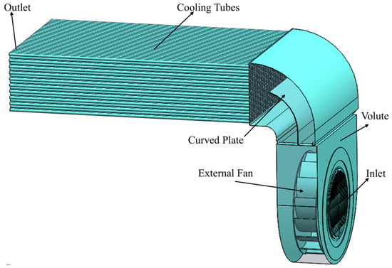
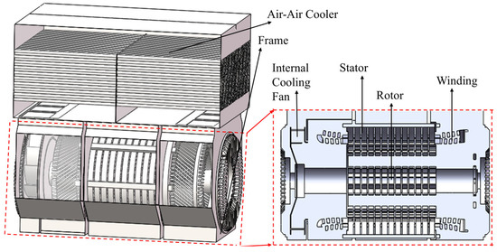
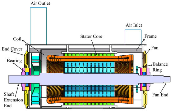
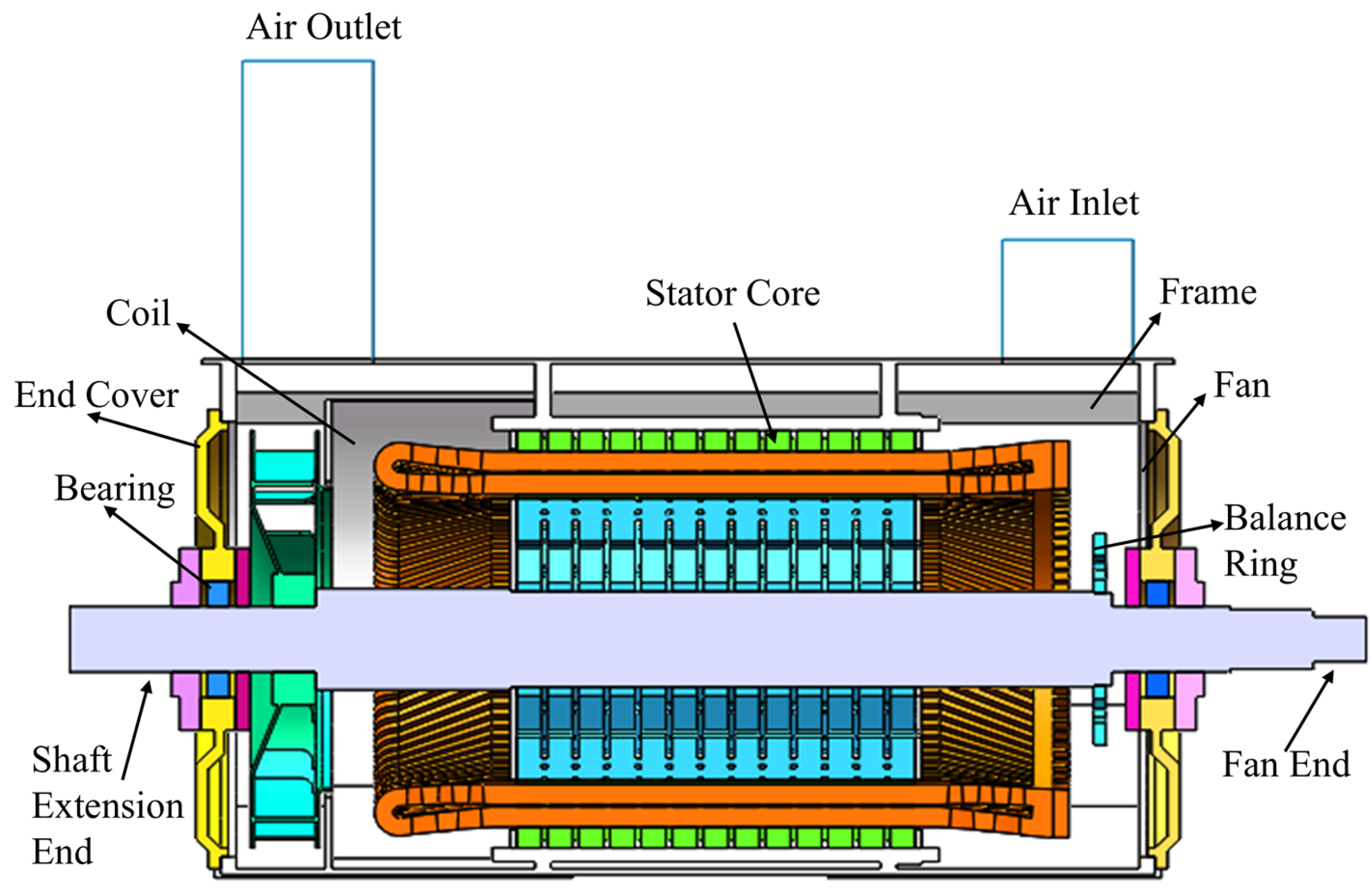
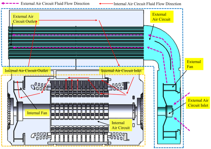
The research object of this paper is the TY400-710 kW high-voltage permanent magnet motor. The permanent magnet adopted is N38SH NdFeB, whose core parameters and structural characteristics are listed in Table 1. This motor adopts a structural design of the totally enclosed type with an air-to-air cooler, and its air circuit system is divided into two parts: the internal and external air circuits. The internal air circuit is a hybrid ventilation system with a closed-circulation structure. A centrifugal fan is installed at the extended end of the motor shaft, which drives the circulating flow of the internal fluid owing to the pressure generated by the fan. An external fan was coaxially mounted on the motor for the external air circuit, which drove the low-temperature ambient air into the cooling tubes. The cooling of the fluid in the internal air circuit was realized through forced convection heat transfer between the inside and outside of the cooling tubes.
Table 1.
Key Motor Parameters and Structures.
2.2. Basic Assumptions
Based on the structural characteristics of the motor and the features of its ventilation and heat dissipation, the following assumptions were made [23,24]:
- (1)
- The fluid in the motor fluid domain had a Reynolds number Re greater than 2300, representing a turbulent flow state; thus, the numerical simulation was performed using a turbulence model.
- (2)
- The fluid velocity is much lower than the speed of sound with an extremely small Mach number; therefore, the fluid is regarded as an incompressible fluid.
- (3)
- The effects of buoyancy and gravity on the fluid in the ventilation ducts were neglected.
- (4)
- Only the steady state of the fluid velocity (steady flow) was investigated, with no time term included in the governing equations.
- (5)
- Laminated silicon steel sheets in the stator core segment were modeled as a whole.
- (6)
- The straight segments of the stator slots are filled and in gapless contact with the stator core, and the end windings are modeled in accordance with their actual winding shapes.
- (7)
- It is assumed that all components inside the motor are in close contact, with no contact thermal resistance between them.
- (8)
- The errors in the motor slots caused by the manufacturing process are neglected.
2.3. Mathematical Models and Simulation Methods
2.3.1. Microhardness Analysis
The modeling and design of the motor in this study were conducted using SolidWorks software 2016 (version 24.0). Local structural features that exert no influence on the flow and temperature fields, such as motor bolt connectors, sealing rings, fillets, and local chamfers, were neglected, and a simplified simulation calculation model of the flow and temperature fields of the motor was established, as shown in Figure 1 and Figure 2. Based on the theory of Computational Fluid Dynamics, a 3D flow field model of the motor’s internal and external air circuits was constructed. With the inlet, outlet, and wall boundary conditions specified, the Finite Volume Method was adopted to solve the fluid governing equations, thereby obtaining the distribution of the velocity, pressure, and flow rate of the cooling air inside the motor [25,26].
Figure 1.
External Air Circuit Fluid Physical Model.
Figure 2.
Internal Air Circuit Fluid Physical Model.
2.3.2. Coupled Calculation of Temperature Field
Following the flow field analysis, the temperature field of the motor body was simulated using the coupled field method. Heat sources including copper loss, iron loss, windage loss and friction loss were taken into consideration, and the thermophysical parameters of various materials were defined. The overall temperature distribution of the motor and the maximum temperatures of key components such as stator windings and permanent magnets were obtained by solving the energy equation. The physical model of the temperature field is presented in Figure 3.
Figure 3.
Temperature Field Physical Model.
2.4. Boundary Conditions
- (1)
- For the external fluid domain of the motor, pressure inlet and pressure outlet boundary conditions were adopted, and the internal fluid domain was a closed circulation system.
- (2)
- In the temperature field calculation, the ambient temperature was set to 28 °C; the inlet flow rate of the internal air circuit was taken as the calculation result of the entire motor fluid domain, that is, 0.6 m3/s, and the inlet temperature was calculated as 38.5 °C based on the energy conservation relationship. The outer surface of the motor underwent natural heat dissipation, with the convective heat transfer coefficient set to 9.73 W/(m2·K).
- (3)
- As a rotating machine, the motor adopts the multiple reference frame method, and the RNG κ-ξ turbulence model is selected, which is combined with the enhanced wall function method [25].
2.5. Mathematical Model
In engineering practice, the flow velocity in the motor fluid domain is much lower than the speed of sound, and the variation in air density is negligible. Thus, air can be regarded as an incompressible fluid, whose flow satisfies the conservation equations of mass, momentum, and energy. The RNG κ-ξ model with enhanced wall treatment can accurately capture the flow characteristics of rotating components, narrow air gaps, and radial ventilation ducts in enclosed air-cooled motors. Its prediction errors for the flow field and temperature field are lower than those of the standard κ-ξ model and the realizable κ-ξ model, making it one of the optimal turbulence models for flow and heat transfer simulations of such motors [20]. Therefore, the RNG κ-ξ model is adopted in this study. This model can accurately obtain the flow intensity and turbulent kinetic energy in the flow field, and its governing equations are presented in Equation (1) [25].
where is the density; P is the pressure; u, v, and w are the velocity components in the x, y, and z directions, respectively; T denotes the temperature; k is the heat transfer coefficient of the fluid; cp represents the specific heat capacity of the fluid; and ST is the heat generated by the internal heat sources of the fluid and the portion of mechanical energy loss converted into the internal energy of the fluid. The empirical constants are as follows: , , , , , , .
3. Numerical Simulation, Calculation and Analysis of the Flow Field
3.1. Analysis of Flow Characteristics in the External Flow Field
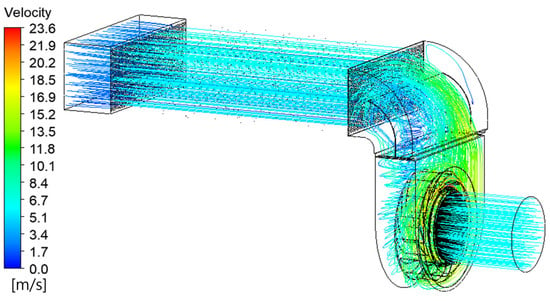
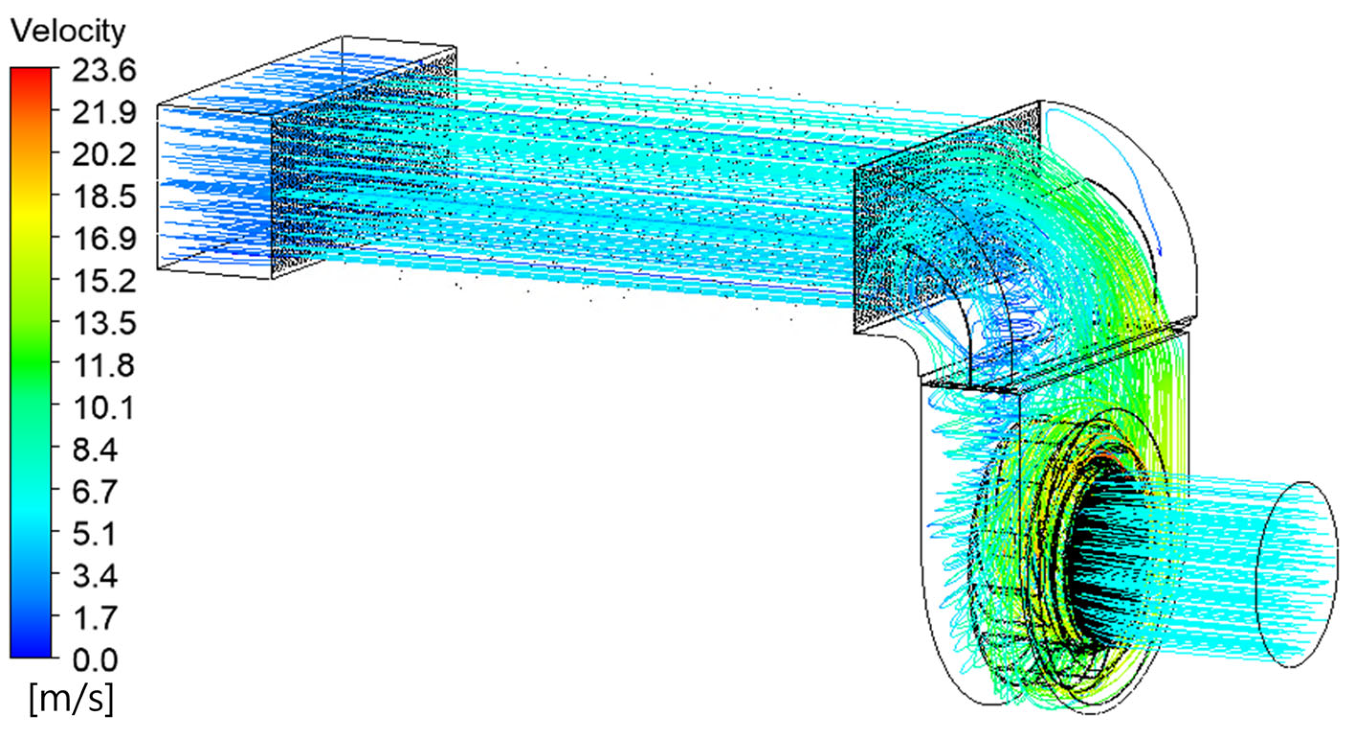
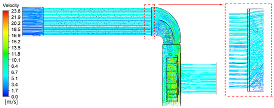
During motor operation, a large amount of heat is generated, and the temperature rise characteristics of the motor are directly determined by the cooling performance of the external air circuit. On the basis of theoretical calculations given in Equation (2), the minimum air volume required for motor cooling is determined to be 1.05 m3/s. Figure 4 shows the flow streamline field of the external air circuit. The overall flow of the air circuit system is smooth, and the external air volume obtained by simulation calculation is 1.2 m3/s, which can theoretically meet the heat dissipation requirements of the motor.
where qv denotes the volume flow rate of the cooling medium, pv denotes the total loss power to be removed by the cooling medium, cp denotes the specific heat capacity of the cooling medium, and Δtv denotes the temperature rise in the cooling medium after passing through the motor.
Figure 4.
External Air Path Fluid Streamline Diagram.
A meridional velocity vector diagram of the external air circuit is shown in Figure 5. It can be observed from the diagram that the flow patterns inside the cooling tubes are similar when the fluid flows through the external air circuit, with a uniform air velocity distribution. The flow velocity was maintained at approximately 8 m/s, causing little impingement on the cooling tubes and indicating a relatively reasonable air velocity level. The air velocity reached its maximum at the fan component, with the peak value being 23.6 m/s, which drove the airflow in the external air circuit. This results in a higher air velocity on one side near the curved plates than on the other side, a phenomenon attributed to the fan rotation direction and the convergence of the airflow. Eddy currents are prone to occur in areas where the cross-sectional shape of the motor structure changes abruptly, and energy loss is inevitable in these regions. The presence of eddy currents reduces the kinetic energy of the fluid and increases the flow losses. In subsequent designs, the structure of the guide plates can be adjusted appropriately to mitigate flow losses.
Figure 5.
Meridional Plane Velocity Vector Diagram of External Air Pathway.
3.2. Analysis of Flow Characteristics in the Internal Flow Field
To guarantee the precision of coupled field calculation, a fluid field analysis was first performed on the complete internal structure of the motor, so as to acquire the inlet velocity boundary conditions and outlet pressure conditions for the coupled field. These boundary conditions are not obtained via hypothetical computations, and more precise internal temperature distribution and computational results of the motor can be achieved by means of a thorough air circuit analysis.
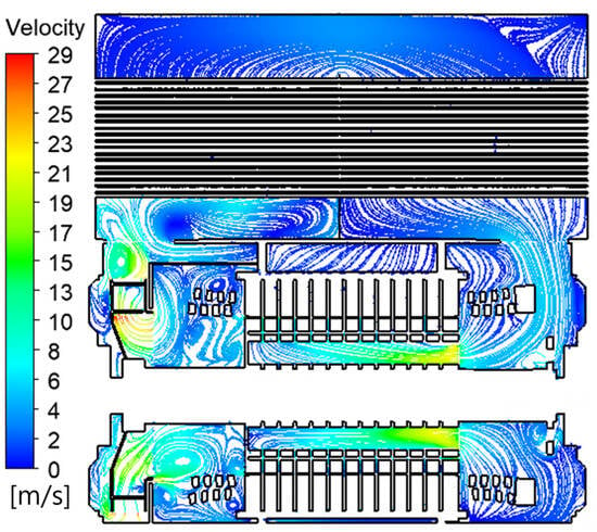
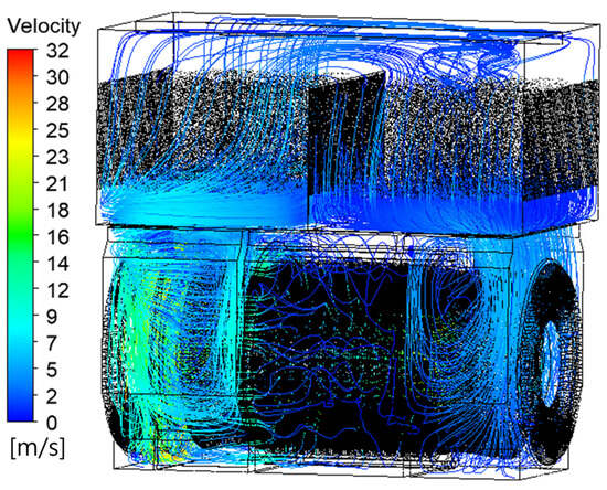
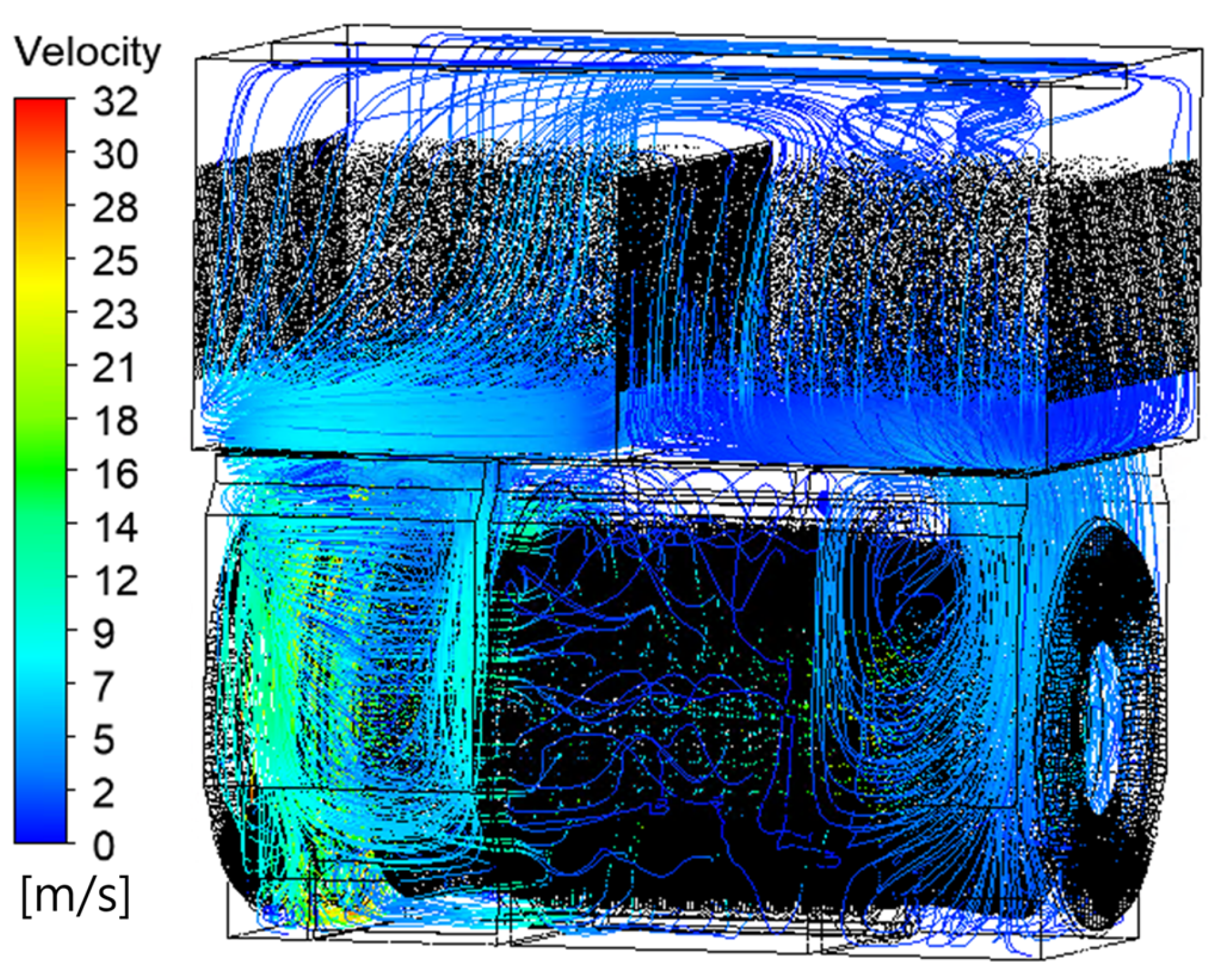
Figure 6 presents the meridional-plane velocity vector diagram. It can be observed that the air velocity is comparatively high in the rotor rotation region and fan region inside the motor, and the flow velocity variation in each air branch of the motor can also be perceived. The internal air velocity peaks near the fan, while the air velocity in the cooler region is comparatively low due to the blocking effect of the cooling tubes. Figure 7 displays the flow streamline diagram of the internal air circuit. Affected by the local structural characteristics inside the motor, the fluid flow in the internal air circuit is relatively complicated, and the average air velocity outside the cooling tubes is 4 m/s with a fairly uniform distribution.
Figure 6.
Meridional-plane velocity vector diagram.
Figure 7.
Fluid Flow Streamline Diagram of the Internal Air Circuit.
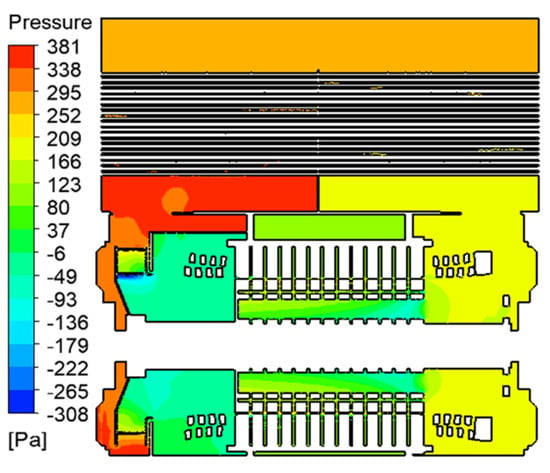
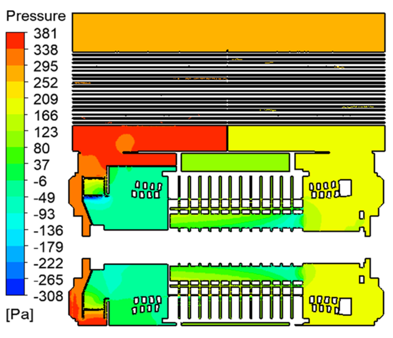
The static pressure contour map distribution of the meridional plane cross-section inside the motor is shown in Figure 8. The pressure distribution and variation law in the entire ventilation duct were consistent with those of the cooling gas flow velocity. The pressure difference on both sides of the air-air cooler was significant, reaching 182 Pa, and there were obvious differences in the pressure difference gradient across different regions. This is conducive to the airflow inside the motor, accelerates the heat flow at the fan end, and enables the air to flow smoothly into the cooler for cyclic cooling and temperature reduction.
Figure 8.
Static Pressure Contour Map of the Meridional Plane.
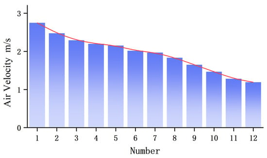
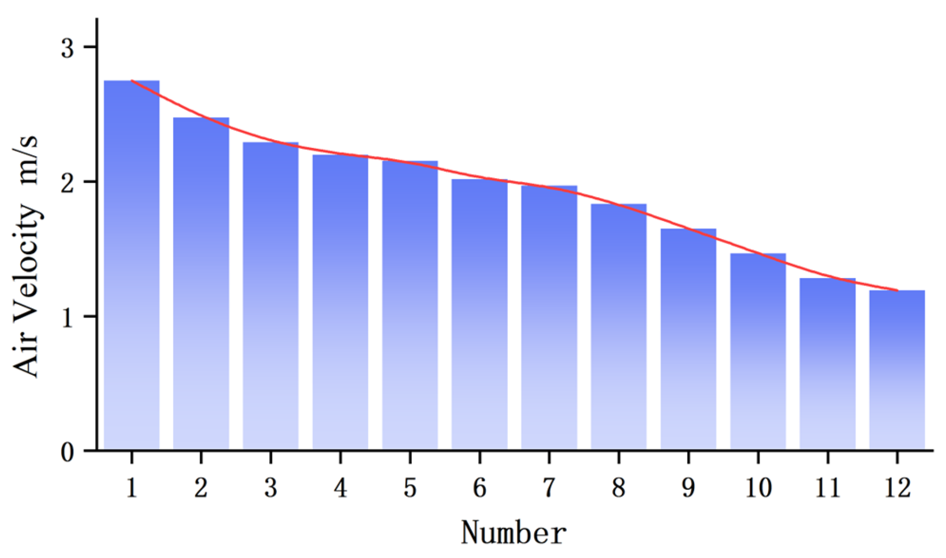
The internal cooling air volume of the motor was 0.6 m3/s, and the mechanical loss of the internal fan was 1.8 kW. The air volume distribution of the stator radial air ducts is illustrated in Figure 9. According to the ventilation calculation results, the air volume distribution of the ducts exhibited a gradually decreasing trend; in particular, the last duct had a relatively small air volume, accounting for only 59.6% of that in the middle duct. This is because this radial air duct is the farthest from the outlet end, resulting in a low air volume and low temperature in this area.
Figure 9.
Air Volume Data of the Stator Radial Air Ducts.
4. Numerical Simulation and Experimental Verification of the Thermal–Fluid Coupled Field
4.1. Numerical Simulation and Analysis of the Coupled Field
Asynchronous motor components involve a variety of materials. Shafts, air baffles, frames, fans, end covers and other parts are isotropic materials. The stator core and rotor core of the motor are made of silicon steel sheets and belong to anisotropic materials. The losses generated during motor operation are converted into heat. Electromagnetic calculations are carried out via finite element simulation, and the loss data of each motor part are listed in Table 2. The heat source densities and thermal conductivities of the main components are given in Table 3, which are applied to the corresponding positions for the coupled-field numerical simulation.
Table 2.
Loss Components.
Table 3.
Heat Source Density and Thermal Conductivity of Main Components.
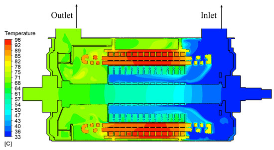
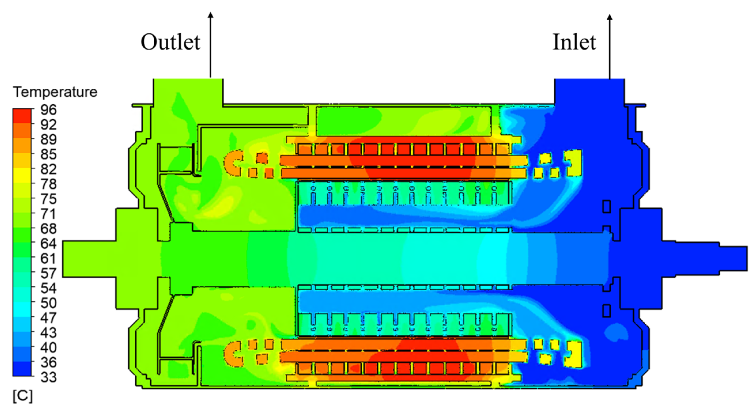
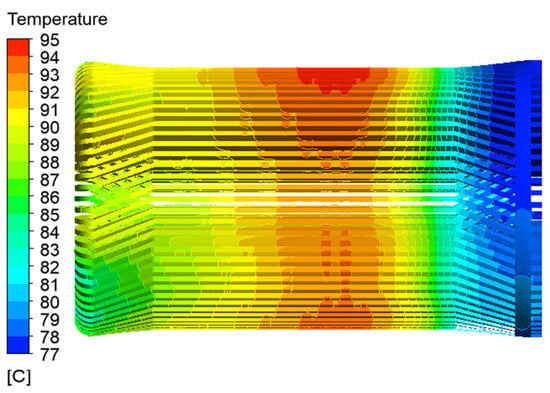
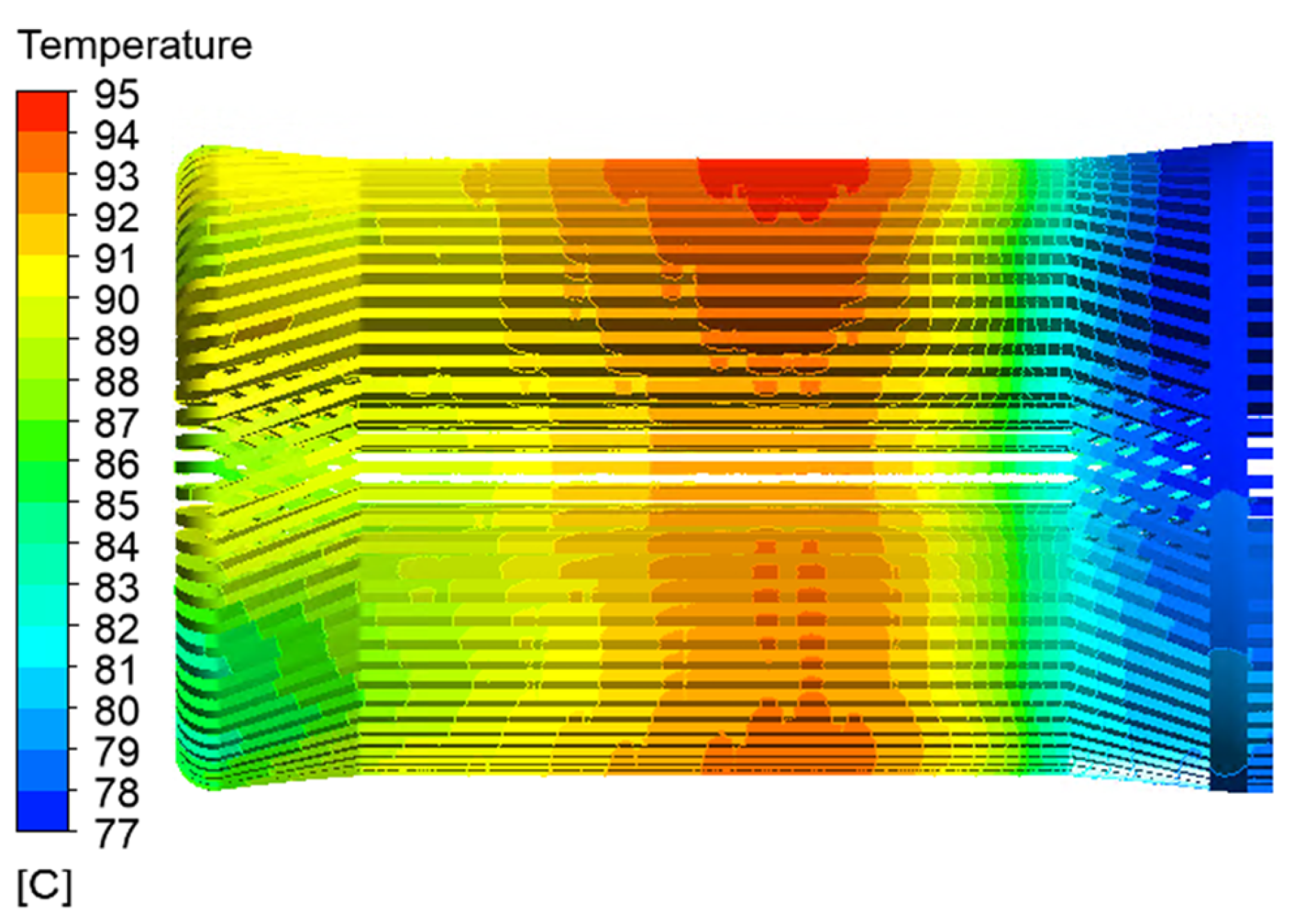
The temperature distribution of the motor in the meridional plane is shown in Figure 10. It can be seen from the diagram that the motor temperature exhibits a gradual increase along the axial direction from the inlet to the outlet, with the stator core reaching a relatively high temperature. As shown in Figure 11, the stator temperature distribution indicates that the maximum temperature of the motor is 96 °C, which occurs at the stator core, near its middle area. In addition, the temperature of the straight section of the winding along the direction from the inlet to the outlet presents a trend of first increasing gradually and then decreasing, whereas the stator winding has a maximum temperature of 95 °C and a minimum temperature of 77 °C. Compared with the motor studied by Li Weili et al. [13], the motor proposed in this paper has a lower winding temperature rise, and the cooling efficiency is improved by approximately 12%.
Figure 10.
Temperature Distribution of the Motor in the Meridional Plane.
Figure 11.
Temperature Distribution of Stator Winding.
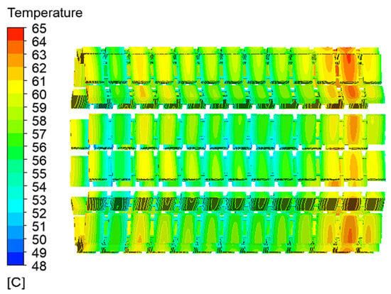
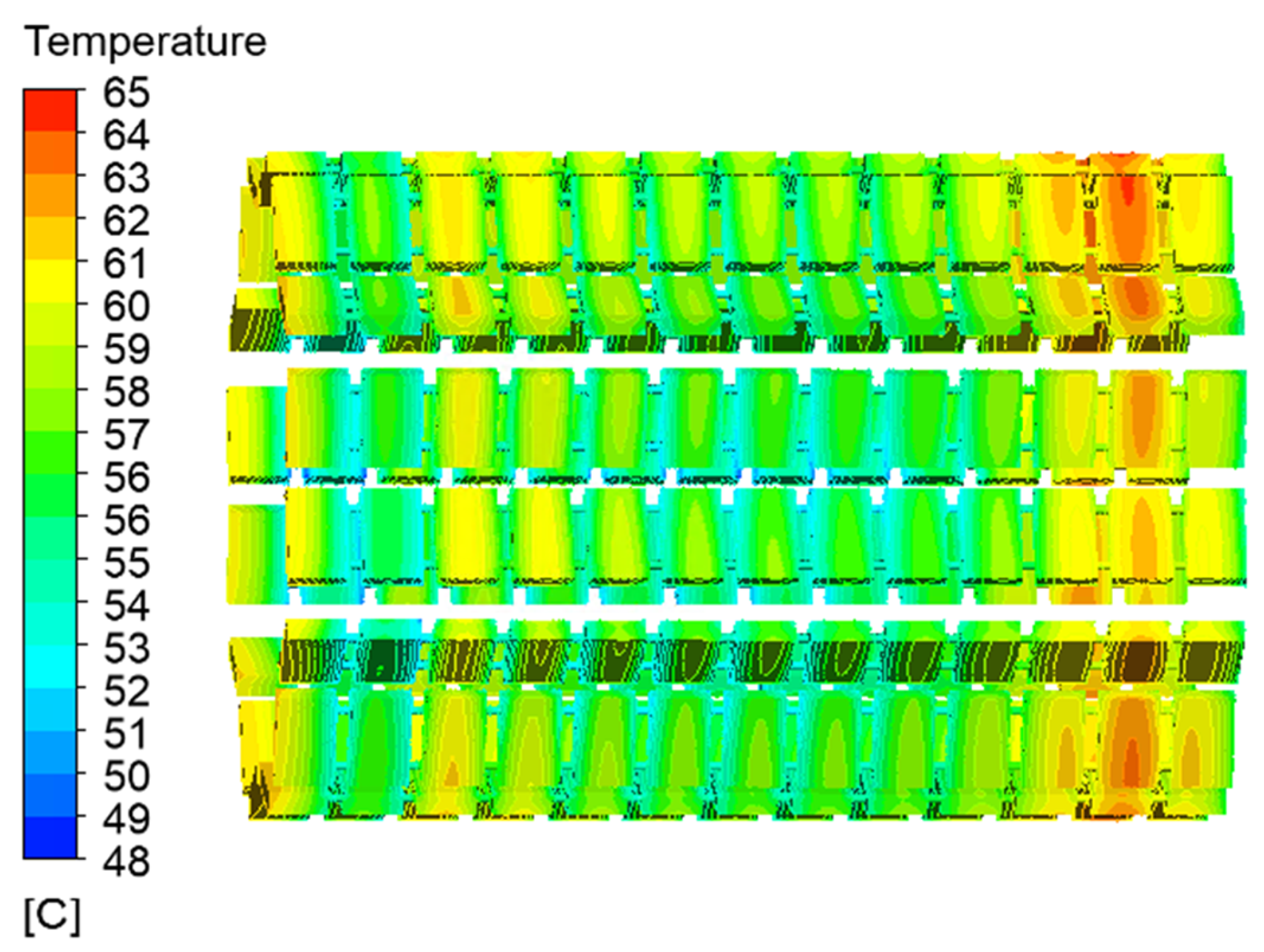
Figure 12 illustrates the temperature distribution of the permanent magnets. The rotor’s permanent magnets attained a maximum temperature of 65 °C, and the rotor’s ventilation and heat dissipation effects were better than those of the stator. This is primarily because the rotor bars and ventilation ducts exert a fan-like function, thereby realizing enhanced convective heat transfer.
Figure 12.
Temperature Distribution of Permanent Magnets.
By combining the ventilation duct design, cooler performance and loss distribution, the reasons why this motor can achieve low temperature rise under high power density are analyzed, and three key influencing factors are obtained:
- (1)
- Optimized hybrid ventilation duct design: The motor adopts a hybrid ventilation system for its internal air circuit, with radial ventilation ducts arranged in a gradient layout. The rotor bars and ventilation slot tubes form a “self-fan” effect, which strengthens the forced convection heat transfer of the rotor. The heat transfer coefficient in the rotor region is increased by about 30%, effectively reducing the permanent magnet temperature.
- (2)
- High-efficiency air-to-air cooler with uniform flow field: The cooler employs staggered heat exchanger tubes. After optimizing the flow field uniformity, its heat transfer efficiency reaches 85%, which ensures effective cooling of the internal circulating air and keeps the inlet temperature of the internal air circuit at a low level.
- (3)
- Reasonable loss distribution and efficient heat transfer paths: Through electromagnetic design optimization, the losses in the stator windings and core are reasonably distributed, and the heat transfer paths of each component are optimized simultaneously. The tight contact among components enables rapid heat transfer from internal heat sources to the cooling medium, reducing the heat transfer resistance in the solid domain by approximately 25%.
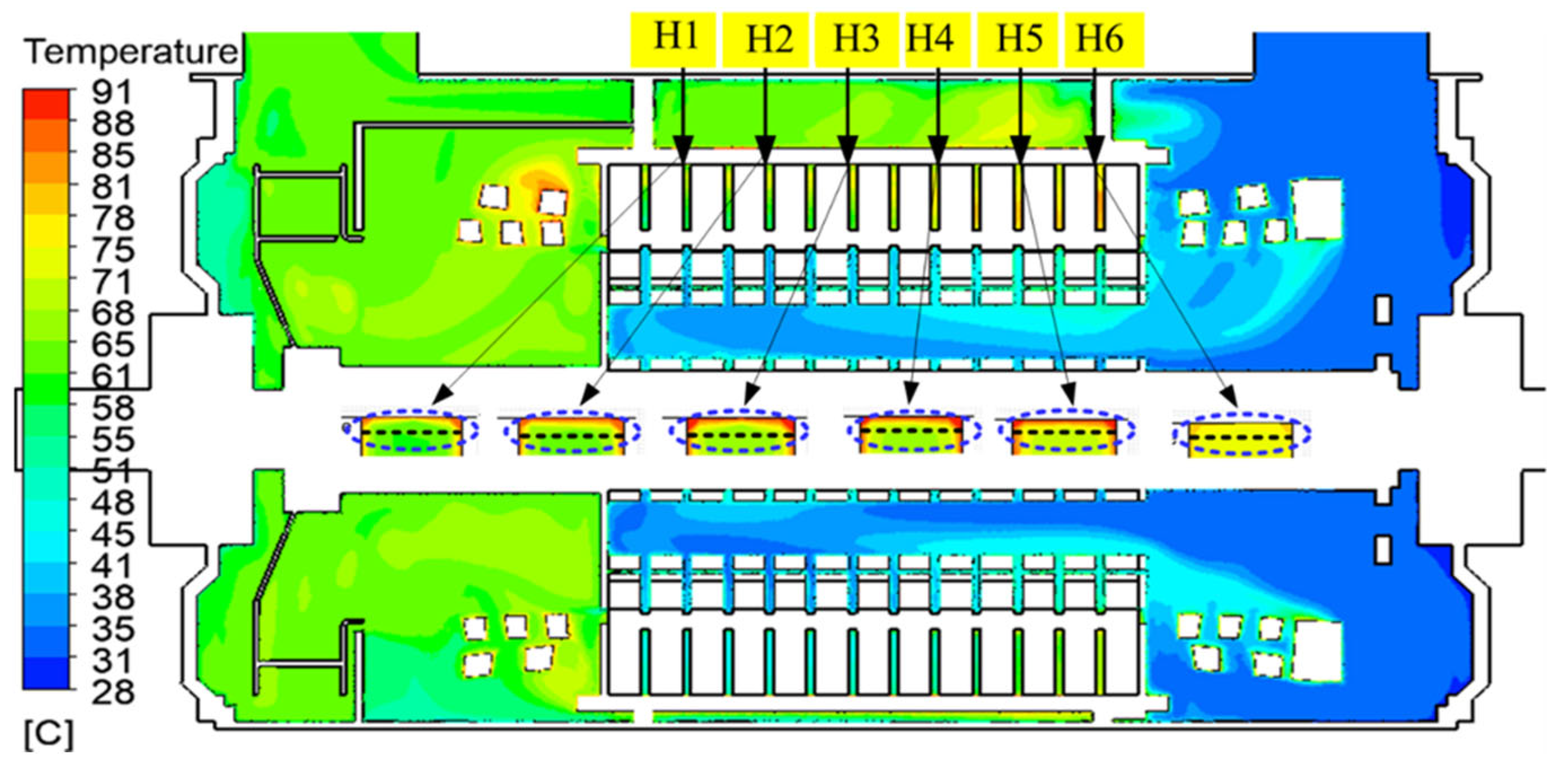
Distribution points H1, H2, H3, H4, H5, and H6 were selected in the radial ventilation ducts, as shown in Figure 13. The temperature simulation results for each stator radial ventilation duct are presented in Table 4. The results in the table show that the air temperature of different stator radial ventilation ducts ranged from 71.8 °C to 81.2 °C.
Figure 13.
Temperature Simulation Nephogram of the Ducts at the Measuring Points in the Radial Ventilation Ducts.
Table 4.
Simulation Results.
4.2. Experimental Verification
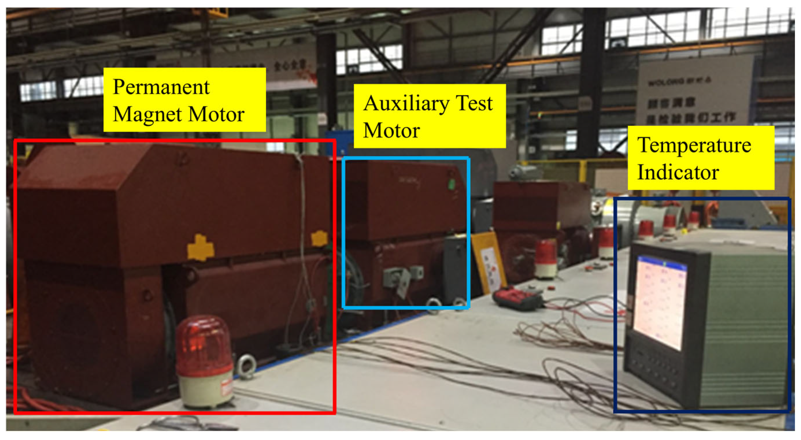
To verify the accuracy of the calculation model and method, a temperature rise test was conducted for the motor under its rated operating conditions, as shown in Figure 14. A test scheme for the performance of the cooling system was designed, and measuring points for the air velocity, air temperature, and radial ventilation duct temperature were arranged at key positions. The test data were recorded and compared with the simulation results.
Figure 14.
Field Test Motor.
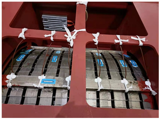
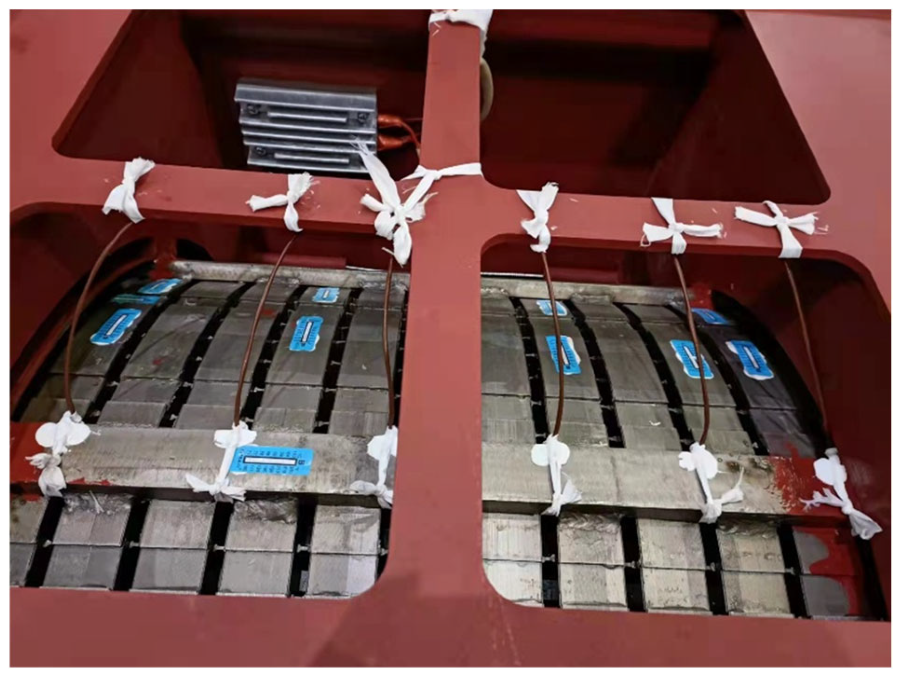
Embedded platinum thermal resistors (Pt100) were used as temperature measuring elements, which were fixed at six air outlets on the back of the stator core, secured by binding, and connected with marked lead wires extended outwards. The DC resistance of the temperature measuring elements was measured both before and after embedding to ensure an unobstructed circuit with no open circuits. The wiring of the test motor is shown in Figure 15.
Figure 15.
Air Temperature Wiring Diagram of the Stator Radial Ventilation Ducts for the Test Motor.
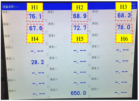
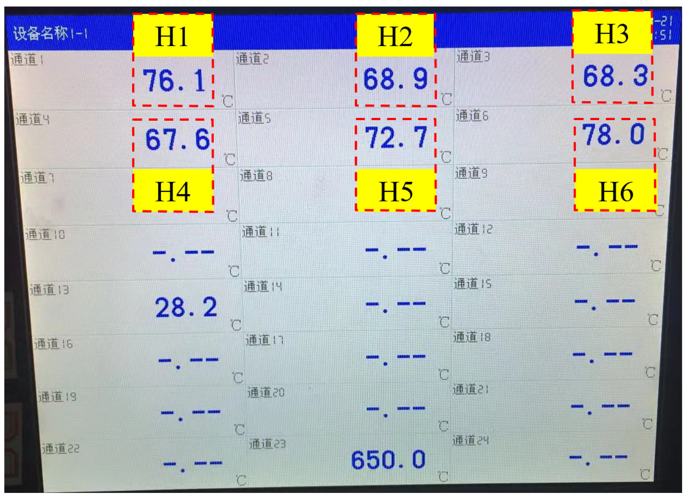
The results of the temperature increase test are shown in Figure 16. The temperature rise error calculated based on the resistance method was 4%, as presented in Table 5, and the relative error was controlled within the 5% limit permitted in engineering practice, which verified the rationality of the numerical simulation method. The thermo-fluid coupled field model has a correct calculation method with accurate and valid results, and it is applicable to the prediction and analysis of motor temperature rise in the product design phase for enterprises.
Figure 16.
Test Results of Air Temperature in the Stator Radial Ventilation Ducts.
Table 5.
Comparison of Simulation and Testing.
5. Conclusions
In this study, a 710 kW high-voltage permanent magnet motor was used as the research object. To address the problems of the lack of full-domain near-real models and insufficient investigation into thermo-fluid coupling laws in the current research on the thermo-fluid characteristics of high-voltage permanent magnet motors, a full-machine flow field and temperature field model covering the internal and external air ducts was established based on the theories of Computational Fluid Dynamics and Numerical Heat Transfer. The Finite Volume Method was adopted to conduct a thermo-fluid coupled numerical simulation, and the effectiveness of the proposed model and method was verified through experimental tests. This study systematically revealed the flow field distribution characteristics of the motor and the laws of temperature coupling and transfer. The main conclusions are as follows.
- The flow characteristics and air volume distribution mechanisms of the internal and external air ducts of the motor were clarified. The simulated air volume of the external air duct reached 1.2 m3/s, which meets the requirement of a minimum air volume of 1.05 m3/s for motor cooling. The flow velocity in the cooling pipes was uniformly and stably maintained at approximately 8 m/s, causing minor impingement on the pipes; the maximum flow velocity of 23.6 m/s occurred only in the fan area. The overall flow performance of the air duct system was excellent, with local eddies existing only at positions with abrupt structural cross-section changes, which provided a clear direction for the subsequent optimization of the flow guide structure. The cooling air volume of the internal air duct and air gap were 0.6 m3/s and 0.05 m3/s, respectively. An effective pressure difference of 182 Pa was formed on both sides of the air-air cooler, ensuring the efficiency of internal airflow circulation. The air volume in the stator radial ventilation ducts presented a gradient-decreasing distribution, with the air volume in the terminal ducts being only 59.6% of that in the middle ducts, and this distribution was correlated with the distance of the ducts from the outlet end. This distribution law provides data support for the optimization of duct structural parameters and balanced distribution of air volume, and verifies the rationality of the design of the motor’s hybrid ventilation structure and air duct system.
- The coupling law of fluid rheology and heat transfer in the stator radial ventilation ducts was revealed. The thermo-fluid coupled simulation results showed that the air velocity in the radial ventilation ducts presented a consistent variation trend, with the flow velocity increasing progressively toward the outlet end and the air temperature exhibiting a gradient rise characteristic. The measured air temperature ranged from 67.6 to 78 °C, whereas the simulated air temperature ranged from 71.8 to 81.2 °C, and the two showed a highly consistent variation trend. The motor temperature increases gradually along the axial direction from the inlet to the outlet, with the stator core and windings being the main high-temperature regions. Among them, the maximum temperature of the stator core reached 96 °C, and the stator winding had a maximum temperature of 95 °C and a minimum temperature of 77 °C. The maximum temperature of the rotor permanent magnets was only 65 °C, which falls within the safe operating range, benefiting from the enhanced convective heat transfer effect of the rotor bars and ventilation slot pipes. This clarifies the key points of temperature control for the motor components.
- The accuracy of the full-domain thermo-fluid coupled field model and numerical calculation method was verified. The simulation results of the coupled field were compared with the test data under the rated operating conditions. Based on the resistance method, the temperature rise error at the six measuring points of the stator radial ventilation ducts was 4%, which fell within the engineering allowable error range of 5%, thereby verifying that the established model can accurately reflect the full-machine thermos-fluid coupling characteristics of the motor. This model overcomes the limitations of traditional local area analysis or structural equivalent simplification and achieves an accurate simulation of the full-domain flow and heat transfer processes in the internal and external air ducts of the motor. This study provides a reliable theoretical basis and engineering reference for the refined design of cooling systems, optimization of temperature rise control strategies, and avoidance of demagnetization risks for high-voltage permanent magnet motors.
Author Contributions
Conceptualization, L.Y., K.Z. and G.L.; methodology, L.Y., K.Z., Q.L. (Qingqing Lü), G.L. and X.W. (Xuandong Wu); validation, L.Y., K.Z., X.W. (Xiaojun Wang), Q.L. (Qun Li) and G.T.; data curation, X.W. (Xuandong Wu), Q.L. (Qun Li), X.W. (Xiaojun Wang) and G.T.; writing—original draft preparation, L.Y., K.Z. and Q.L. (Qingqing Lü); writing—review and editing, X.W. (Xiaojun Wang) and Q.L. (Qingqing Lü); supervision, L.Y., K.Z., Q.L. (Qingqing Lü) and G.L.; project administration, Q.L. (Qun Li), G.T., X.W. (Xiaojun Wang) and X.W. (Xuandong Wu); funding acquisition, G.L. All authors have read and agreed to the published version of the manuscript.
Funding
This research was funded by Key R&D and Promotion Special/Tackling Key Problems in Science and Technology in Henan Province, China (grant Nos. 252102241063, 252102220130); Henan Province Science and Technology Research and Development Joint Fund (Industrial Category) (grant Nos. 202324119, 20250104); Key Scientific Research Fund of Pingdingshan University (grant Nos. SYJX2024033, 2023-JYZD01).
Institutional Review Board Statement
Not applicable.
Informed Consent Statement
Not applicable.
Data Availability Statement
All relevant data are available in this article.
Acknowledgments
During the preparation of this manuscript, the authors used PaperPal (v0.1.0) for language editing assistance and Grammarly (v1.5.33) for linguistic polishing. The authors have reviewed and edited the output and take full responsibility for the content of this publication.
Conflicts of Interest
Authors Xiaojun Wang and Xuandong Wu were employed by the company Wolong Electric Nanyang Explosion Protection Group Co., Ltd. The remaining authors declare that the research was conducted in the absence of any commercial or financial relationships that could be construed as a potential conflict of interest.
References
- Xie, B.C.; Zhang, Y.; Wang, J.Q.; Liang, B.X.; Zhang, F.G. An efficient multidisciplinary design research for the integrated low speed permanent magnet motor system based on analytical and numerical hybrid analysis. Energy Rep. 2022, 8, 199–208. [Google Scholar] [CrossRef] [Scilit]
- Sánchez, S.I.S.; Silva, P.M.; Peregrino, O.H.V.; Aldaco, S.E.D.L.; Sánchez, A.C.; García, C.C. Analysis and Design Methodology of Radial Flux Surface-Mounted Permanent Magnet Synchronous Motors. Eng 2023, 4, 2840–2855. [Google Scholar] [CrossRef] [Scilit]
- Du, G.H.; Xu, W.; Zhu, J.G.; Huang, N. Power Loss and Thermal Analysis for High-Power High-Speed Permanent Magnet Machines. IEEE Trans. Ind. Electron. 2020, 67, 2722–2733. [Google Scholar] [CrossRef] [Scilit]
- Florina-Ambrozia, C.; Iulia, V.; Loránd, S. On the Usefulness of Employing ANSYS Motor-CAD Software in Designing Permanent Magnet Synchronous Machines. Designs 2023, 7, 7. [Google Scholar] [CrossRef] [Scilit]
- Brody, R.; McIntyre, M.; Grainger, B. Online Permanent Magnet Temperature Estimation in Permanent Magnet Machines Using Nonlinear Observer with Enhanced Parameter Estimation to Minimise Risk of Demagnetization. IET Electr. Power Appl. 2025, 19, e70043. [Google Scholar] [CrossRef] [Scilit]
- Gao, J.; Li, C.X.; Zhang, W.J.; Huang, S.D. Permanent magnet temperature estimation of high power density permanent magnet synchronous machines by considering magnetic saturation. J. Power Electron. 2021, 21, 1804–1811. [Google Scholar] [CrossRef] [Scilit]
- Zhang, W.; Li, G.J.; Zhu, Z.Q.; Ren, B.; Chong, Y.C. Semi-flooded cooling for high torque density modular permanent magnet machines. IET Electr. Power Appl. 2024, 18, 756–765. [Google Scholar] [CrossRef] [Scilit]
- Xu, Y.P.; Zheng, A.; Zhou, J.; Jin, C.W.; Ling, Y.Y.; Li, Y.N. Research on Multi-Field Coupling and Heat Transfer Characteristics of Air-Cooled High Speed Magnetically Suspended Permanent Magnet Synchronous Motor. J. Mech. Eng. 2025, 1–10. Available online: https://kns.cnki.net/kcms2/article/abstract?v=oP9ZHfsbLHMVELq_O7RunqkvUWvBmGdoJEHAVm-6E8IoG4REYxkJguz86Sc0DLtogC9vWEZeoRcmctMfNV0xaSkDtaOcqxbTwy5h3_zfdfYShD9_1QsrhheyggCMgZInnlgX6VlYtOGrZWSNwaWbi9KSQaD-3u4riUlgnrgTMxM=&uniplatform=NZKPT (accessed on 15 February 2026).
- Adamou, A.A.; Alaoui, C.; Diop, M.M.; Skorek, A. Squirrel Cage Induction Motors Accurate Modelling for Digital Twin Applications. Modelling 2024, 5, 1582–1600. [Google Scholar] [CrossRef] [Scilit]
- Qü, H.L.; Wu, S.N. Hybrid Cooling Design and Analysis of Heat Pipe of Axial Flux Permanent Magnet Motor. Small Spec. Electr. Mach. 2025, 53, 1–5. [Google Scholar] [CrossRef]
- Chen, B.Y.; Cao, J.W.; Liu, Y.Q.; Song, Y.C.; Li, L.Y. Design Method for Maximum Output Power of Rocket High-Power Density Cryogenic Electric Pumps. Trans. China Electrotech. Soc. 2025, 40, 7238–7249. [Google Scholar] [CrossRef]
- Sharifi, T.; Eikani, A. Heat transfer investigations on a thermally superior alternative for the flux switching permanent magnet electric motor. Results Eng. 2024, 24, 103415. [Google Scholar] [CrossRef] [Scilit]
- Li, W.L.; Chen, T.T.; Cao, J.C.; Qu, F.B.; Zhang, Y. Thermal-insulation analysis of permanent magnets in high voltage PMSM. Electr. Mach. Control 2012, 16, 12–18. [Google Scholar] [CrossRef]
- Zhu, Y.C.; Sun, Y.W.; Liu, S.H.; Yan, J.H.Y.; Zhai, L.; Zhang, M.D. Study on Internal Flow and Heat Dissipation Characteristics of Oil-Cooled Electric Motors Based on Multiphase Flow Model. Automot. Eng. 2025, 47, 1803–1813+1825. [Google Scholar] [CrossRef]
- Zhu, M.C.; Wu, L.J.; Liu, D.L.; Shen, Y.M.; Li, R.D.; Wen, H. Comparative Study of Dual-Stator Permanent Magnet Machines with Different PM Arrangements and Rotor Topologies for Aviation Electric Propulsion. Machines 2025, 13, 273. [Google Scholar] [CrossRef] [Scilit]
- Chen, W.Q.; Song, A.J. Study on Temperature Rise Characteristics and Heat Dissipation Optimization Design of Explosion-proof Permanent Magnet Motor for Mining. Sci. Technol. Innov. 2026, 02, 205–208. Available online: https://kns.cnki.net/kcms2/article/abstract?v=oP9ZHfsbLHOAdlGUGTNZwo08RqCBnlttFKT92goA0b5dAzXwkClwTlt0ZIwcAJAy1QDkVI9jbVuduiM4j7gdXzILKmGJob4tBJ3FHDEHUGt15XOPTDbnXPB9hgpT5ARVwi7S8CJybmCaypPcBttFD0wLs1spcDII&uniplatform=NZKPT (accessed on 15 February 2026).
- Gao, W.; Wu, Y.X.; Deng, Z.W.; Wang, B.H. Temperature Field Analysis and Optimization of Non-Smooth Water Cooling Channel for Permanent Magnet Synchronous Motor. Mach. Des. Manuf. 2025, 12, 125–132. [Google Scholar] [CrossRef]
- Li, W.; Cao, Z.; Zhang, X. Thermal Analysis of the Solid Rotor Permanent Magnet Synchronous Motors with Air-Cooled Hybrid Ventilation Systems. IEEE Trans. Ind. Electron. 2022, 69, 1146–1156. [Google Scholar] [CrossRef] [Scilit]
- Verkhovtsev, D.; Gulay, S. Numerical simulation of the rotor winding temperature field with self-ventilation from the sub-slot duct. IOP Conf. Ser. Mater. Sci. Eng. 2019, 643, 012021. [Google Scholar] [CrossRef] [Scilit]
- Xue, H.J.; Tan, D.; Liu, S.S.; Yuan, M.; Zhao, C.M. Research on the Electromagnetic-Heat-Flow Coupled Modeling and Analysis for In-Wheel Motor. World Electr. Veh. J. 2020, 11, 29. [Google Scholar] [CrossRef] [Scilit]
- Camilleri, R.; Howey, A.D.; McCulloch, D.M. Predicting the Temperature and Flow Distribution in a Direct Oil-Cooled Electrical Machine with Segmented Stator. IEEE Trans. Ind. Electron. 2016, 63, 82–91. [Google Scholar] [CrossRef] [Scilit]
- Bazi, E.N.; Guennouni, N.; Mekhfioui, M.; Goudzi, A.; Chebak, A.; Mabrouki, M. Predicting the Temperature of a Permanent Magnet Synchronous Motor: A Comparative Study of Artificial Neural Network Algorithms. Technologies 2025, 13, 120. [Google Scholar] [CrossRef] [Scilit]
- Mohd, H.M.R.; Tak, C.Y.; Wai, C.L.; Paw, K.S.; Amirani, A.N. Numerical Analysis on the Performance of a Radiant Cooling Panel with Serpentine-Based Design. Energies 2021, 14, 4744. [Google Scholar] [CrossRef] [Scilit]
- Lü, Q.Q.; Wang, X.J.; Yang, L.Q.; Tian, G.W.; Li, G.X. Optimization Design and Experimental Study of Cooling System in a High Voltage Induction Motor after Power Density Upgrade. Recent Adv. Electr. Electron. Eng. 2023, 16, 560–570. [Google Scholar] [CrossRef] [Scilit]
- Gao, L.L.; Liu, X.; Liu, H. Analytical Calculation of Magnetic Field and Temperature Field of Surface Mounted Permanent Magnet Synchronous Motor. J. Electr. Eng. Technol. 2025, 20, 2249–2262. [Google Scholar] [CrossRef] [Scilit]
- Yi, Y.L.; Ma, S.; Zhang, B.; Feng, W. Application of High Efficiency and High Precision Network Algorithm in Thermal Capacity Design of Modular Permanent Magnet Fault-Tolerant Motor. Energies 2025, 18, 3967. [Google Scholar] [CrossRef] [Scilit]

Disclaimer/Publisher’s Note: The statements, opinions and data contained in all publications are solely those of the individual author(s) and contributor(s) and not of MDPI and/or the editor(s). MDPI and/or the editor(s) disclaim responsibility for any injury to people or property resulting from any ideas, methods, instructions or products referred to in the content. |
© 2026 by the authors. Licensee MDPI, Basel, Switzerland. This article is an open access article distributed under the terms and conditions of the Creative Commons Attribution (CC BY) license.