


Abstract
Accelerator capabilities beyond those of conventional drivers for compact accelerator-driven neutron sources (CANSs) are needed to serve applications that require high neutron flux, while remaining compact. These applications include—among others—fusion reactor materials testing, medical isotope production, tritium breeding, and nuclear waste transmutation. The deuteron cyclotron auto-resonance accelerator (dCARA) has been proposed as a compact CANS driver that would replace the conventional radiofrequency quadrupole and superconducting radio frequency linac chain with a single rotating-mode transverse electromagnetic cavity operating in a multi-tesla magnetic field. This paper provides an overview of the current readiness and feasibility of dCARA for this role by synthesizing the theory, simulation, and conceptual design studies, while employing specifications of available subsystem technologies. These include high-current deuteron ion sources, large bore multi-tesla superconducting magnets, and high-power radiofrequency systems. The simulations of ion acceleration in dCARA are consistent with analytical predictions. Furthermore, hardware for each major subsystem has already reached a high level of performance and technology readiness in developments for related systems. Integrated engineering design and experimental validation are ongoing, with the aim of extending CANS technology into high-flux application regimes based on use of the dCARA driver.
1. Introduction
Neutron sources underpin a wide range of applications [1,2]—from neutron scattering, imaging, and elemental analysis to irradiation testing, isotope production, and transmutation—that have traditionally relied on research reactors or large spallation facilities. Compact accelerator-driven neutron sources (CANSs) [3], which generate neutrons by directing low- or medium-energy proton or deuteron beams onto light-element targets, offer a smaller, lower-cost, and more flexible alternative suited to deployment at universities, hospitals, and regional facilities. However, the limited beam power of most existing CANSs confines them to low- or medium-flux applications; higher-fluence applications—such as fusion materials testing, tritium breeding, and nuclear waste transmutation [1,4,5]—require substantially greater accelerator current and beam power, which can only be achieved almost exclusively by large-scale drivers such as high-energy cyclotrons and RFQ-DTL/HWR linacs or synchrotrons [6,7,8,9,10,11,12,13,14]. This gap highlights the need for accelerator capabilities beyond those of conventional compact drivers to serve high-flux applications while preserving the compactness that makes CANSs attractive.
Accordingly, the objective of the present work is to investigate the feasibility of a novel CANS configuration, namely the deuteron Cyclotron Auto-Resonance Accelerator (dCARA) [15,16,17]. This differs fundamentally from conventional accelerator architectures, with the potential to provide intense neutron fluence from deuteron breakup that is comparable to that from those large accelerator facilities. As such, dCARA does not aim for high neutron brightness, but rather, it identifies parameters such as high beam power, compactness, reliability, efficiency, and cost-effectiveness as current R&D objectives. But while increasing beam power raises neutron production—as with all high-power systems—it also increases target heat deposition, thermal stress, radiation damage, activation, shielding requirements, and engineering complexity. As the focus of this paper is on the accelerator itself, important topics such as neutron production target design, radiological safety, and regulatory considerations will not be addressed in this paper.
The remainder of this paper is organized as follows. Section 2 reviews the CARA acceleration mechanism and compares numerical simulation results with analytical predictions. Section 3 describes the dCARA system architecture and presents technical feasibility evidence of major subsystems. Section 4 summarizes the paper.
2. Cyclotron Auto-Resonance Acceleration Mechanism
Cyclotron auto-resonance is a regime of charged-particle dynamics in a static magnetic field in which a particle gyrating at its relativistic cyclotron frequency remains in phase with a transverse electromagnetic wave even as its energy, and therefore its relativistic mass, increases. The acceleration mechanism was first investigated theoretically in the 1960s [18] and demonstrated experimentally for electrons in the 1990s [19]. It differs fundamentally from bunched-beam acceleration exploited in linear accelerators, conventional cyclotrons, and multi-pass machines, where particles gain energy in discrete structure gaps or cavities within a narrow temporal RF phase window. In CARA devices, particles instead gain energy continuously while gyrating, over many RF cycles, without bunching.
The dCARA concept extends this mechanism to ion acceleration in general, with deuterons as examples, using a rotating transverse electromagnetic (TEM) cavity mode. A TEM-mode cavity was chosen because its transverse dimension can be made substantially smaller, at a given operating frequency, than a corresponding transverse-electric (TE) mode cavity—a size reduction that is essential in practice for fitting a working cavity inside the bore of a realistic superconducting magnet similar to MRI magnets. The cavity supports a quarter-wave (QWR) or half-wave (HWR) resonant rotating-dipole mode, with RF fields surrounding four axially oriented rods that are driven using four coupling loops with successive 90° phase increments [15,17]. A simple left-hand grip rule can be used to identify the proper chirality of the rotating dipole field: with the left thumb pointing along the static B field direction (z direction), the rotation of the dipole field follows the curl of the left hand, and so does the trajectory direction of positive charged particles. Analytical theory—as summarized in Appendix A—and particle simulations predict—as in an example described below—the acceleration in a QWR of a 15–140 mA deuteron beam from an injection energy near 100 keV to 40 MeV within a structure 1–2 m in length, using a 5–10 T superconducting solenoid and RF power at 38–76 MHz, with a simulated RF-to-beam efficiency well above 50% [15].
An idealized analytical theory for acceleration in a standing rotating TEM field has been derived by the present authors [17] using a simplified model to elucidate the dCARA acceleration principle and to determine approximate scaling laws, which can provide useful guidance for estimating the operating parameters of dCARA accelerators. For ions injected into a QWR TEM-mode standing-wave rotating field with specified RF electric field amplitude E0 (as defined in Equation (A2) in Appendix A) at an operating frequency f, wavelength λ, and the cavity immersed in a uniform static axial magnetic field B0, the analytical results lead, for moderate ion acceleration with energy gain of tens of MeV/u under a weak acceleration field, to approximate scaling laws, which are summarized in Appendix A and listed in Table 1 specifically for deuterons. For QWR, the normalized RF electric field parameter shall include a form factor χ to include the effects from shorter acceleration length (L~λ/4) and the skewness of the field distribution. The empirical approximation value of χ is around 0.5 to 0.6 for HWR, χ = 1. Note that the energy gain is approximately proportional to the square of E0 and so is linearly proportional to the RF power. As an example of applying Table 1 to give a prediction of beam property, with B0 = 5 T, f = 38 MHz, E0 = 3 MV/m, initial beam energy W0 = 100 keV and χ = 0.55 of a QWR deuteron acceleration, the estimation is the energy gain ΔW = 44.6 MeV and gyration radius ρ = 26.9 cm.
Table 1.
Summary of results of approximate analytical theory for the case of deuteron acceleration in a QWR dCARA model [17].
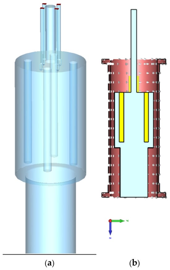
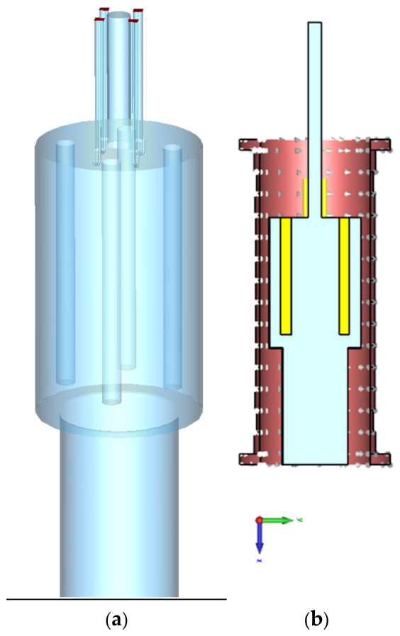
A conceptual design for a 40 MeV, 5 MW dCARA, including a 5 T magnet surrounding the cavity, is modeled to demonstrate this beam acceleration mechanism, as shown in Figure 1. It shows that the cavity comprises an outer cylinder with an upper end plate from which four cylindrical rods are suspended and interspersed with four RF input coupling loops. This example is for a quarter-wave cavity, so the rods terminate before the end of the cavity, after which a RF cutoff beam pipe conveys the accelerated beam downstream. The large cavity aperture allows for relatively generous tolerance to misalignment and beam losses, contributing to good operational reliability. A long superconducting solenoid provides a rather-uniform magnetic field along the cavity axis.
Figure 1.
Conceptual accelerator structure used in beam dynamic simulation. (a) A vertically positioned dCARA cavity, comprising an outer cylinder with an upper end plate from which four cylindrical rods are suspended, with the z-direction pointing downwards. (b) A cross-section view showing a 5 T magnet surrounding the cavity structure, where the yellow region indicates the copper wall, the cyan region as cavity inner space, and the red region as the solenoid coils in the superconducting magnet.
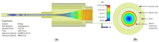
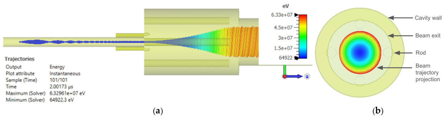
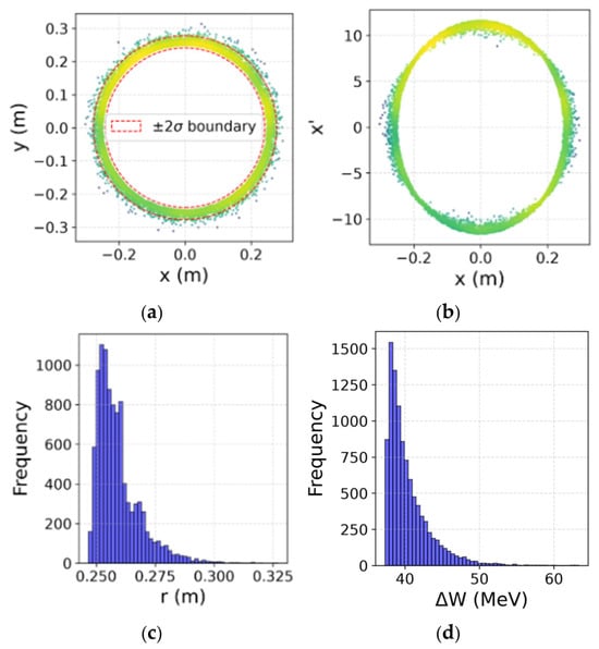
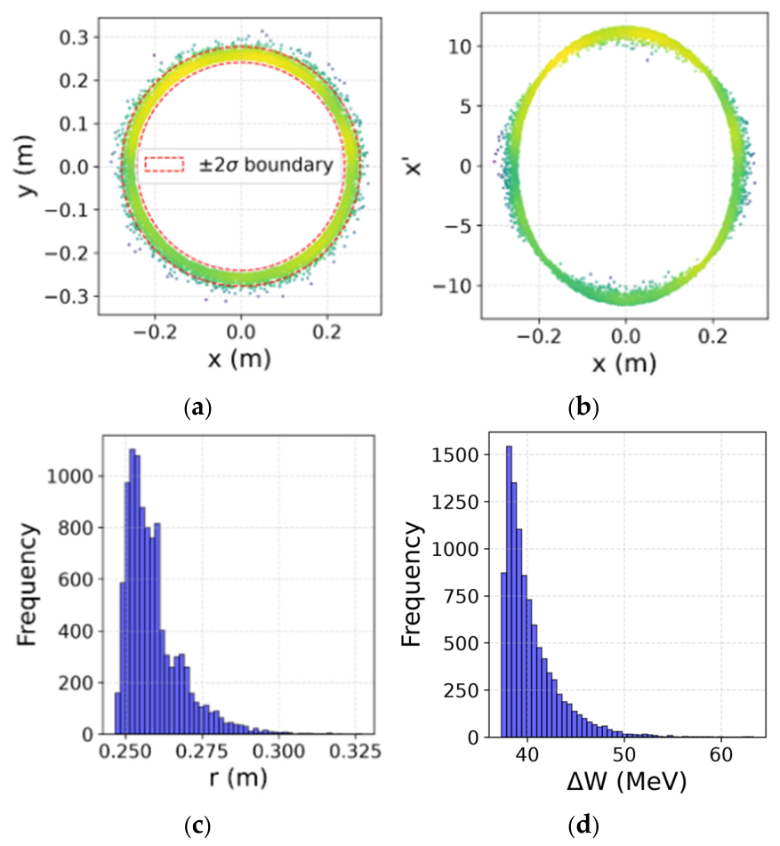
A beam dynamics simulation was carried out for this arrangement, using CST Particle Studio Tracking solver (version 2025.04) with space charge effects included. Figure 2 shows the deuteron trajectories up to and within the dCARA cavity. The main parameters and results of the simulation are listed in Table 2. The dimension, geometry and quality factor of the cavity, the total RF power, the current and initial energy of the deuteron beam, and the profile of static magnetic field must still be optimized and tailored to the requirements such as neutron spatial distribution, spectra distribution and fluence when the accelerated deuteron beam is used to produce neutrons. Careful design of low-energy beam transport (LEBT) and beam matching are needed—not optimized in Figure 2—to reduce the beam scalloping at the cavity entrance and improve the beam quality. Discussion of the high-energy beam transport (HEBT) to match the output beam to a specific neutron production target is beyond the scope of this paper. In this simulation, the initial injected deuteron D+ beam is specified with a beam current 140 mA, kinetic energy 100 keV, normalized rms transverse emittance 0.125π mm mrad and Twiss parameters α = −5.35 and β = 0.23 mm/π mrad, similar to the design beam parameter at the entrance of the IFMIF RFQ [20]. The resulting energy of the output deuteron beam has a mean value of 40.3 MeV and a standard deviation of σW = 2.8 MeV, which matches well with the theoretical prediction. The phase-space diagrams at the dCARA cavity exit are shown in Figure 3. Finite beam size, non-parallel beam injection and space-charge effect lead to a small fraction (<<1%) of the particles exhibiting trajectories with larger radius closer to the rods, experiencing stronger RF electric field and being accelerated to a high energy of 63.3 MeV, as indicated by the tails of the histogram in Figure 3d. There is no beam intersection with the cavity structure, indicating a 100% beam transition. While the space-charge effect is included in this simulation, other causal factors of beam losses such as beam halo and residual gas are not considered but shall be investigated in future studies. The particle simulation shows no evidence of beam breakup or bunching over the acceleration length, presumably due to the continuous, phase-independent nature of the CARA acceleration mechanism [17], which can mitigate space-charge instability, in contrast to stability issues with bunched beams. Further, the dCARA acceleration also demonstrates good detuning tolerance against magnetic field error and RF phase imbalance. A 1000 parts per million (ppm) drift of the magnetic field strength can only cause two percentage change of the beam exit energy, while typical temporal stability of superconducting magnets is much better than 1 ppm per hour. And ten degrees of phase imbalance between two dipole modes can only reduce the beam exit energy by one percent, while such a phase imbalance can be readily compensated by a phase shifter or a low-level input RF adjustment if each mode is driven by different RF sources. These features, together with low-frequency operation, also enhance tolerance to fabrication-induced dimensional deviation and operational thermal instability.
Figure 2.
Beam trajectory from tracking simulation with space charge effect included, with (a) side view and (b) front view. The rods with a radius of 8 cm are equally distributed on a circle of 45 cm in radius, clear of any beam intersection. In this simulation, the total number of macro-particles is 10,000, with each carrying 367.4 femto-Coulomb charge, normalized rms transverse emittance 0.125π mm mrad, Twiss parameters α = −5.35 and β = 0.23 mm/π mrad, and a uniform longitudinal distribution along the travel distance within one RF cycle to represent an all-phase injection at the upstream of the dCARA cavity.
Table 2.
Main parameters and results of the simulation shown in Figure 2.
Figure 3.
Beam phase diagrams of (a) x-y, (b) x-x′; histograms of (c) beam radial position and (d) beam energy, at the exit of the dCARA cavity. The gyration radius r is 25.9 cm with σr = 0.9 cm, and 99.7% of particles exit with gyration radius less than 30 cm; the beam energy gain ΔW is 40.3 MeV with σW = 2.8 MeV, 25th percentile = 38.4 MeV and 75th percentile = 41.5 MeV. Less than 1% of the particles exceed 50.6 MeV.
It is worth noting that the cylindrical shape of the rod in this simulation is adopted for its simplicity. Optimization of the rod cross sections can reduce wall loss significantly. With the specification listed in Table 2, for a heavy beam loading of accelerating 140 mA D+ from 100 keV to 40.3 MeV, the RF power budget for the system will be about 10 MW peak with 5.6 MW power transferred from the RF fields to the ions, which leads to a RF-to-beam efficiency of about 56%. For applications where only a low beam current is needed, the space charge effect and beam trajectory aberration are less severe, so a full beam transmission is still substantiated, and the RF power budget can be reduced accordingly with a reduced RF-to-beam efficiency.
3. Feasibility of dCARA Subsystems
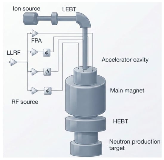
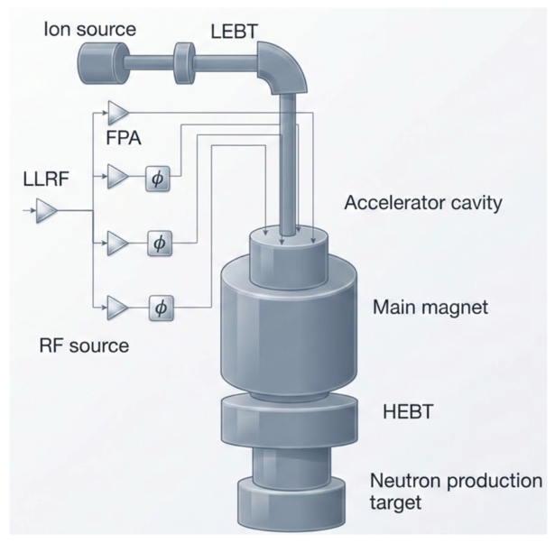
Theory and simulation results give strong evidence to support the possibility of accelerating a high current deuteron beam to reach—as an example—a high-energy 40 MeV in less than a few meters. Figure 4 shows a schematic of a compact dCARA system for neutron source application. A low-energy deuteron beam of tens of keV from an ion source is transported by an LEBT to a dCARA cavity. The cavity is immersed in a large bore superconducting solenoid. The deuteron beam will be accelerated, transported by an HEBT, and directed into a neutron production target, where a high flux of neutrons is generated via the process of deuteron breakup. Without the needs of RFQ and DTL as in ion linear accelerators to reach tens of MeV levels, the accelerator structure of dCARA will only require a much smaller footprint less than 10 m in length. Instead of following the conventional separation between neutron production, moderation, and application regions, this alternative design is to develop compact architectures that intimately couple together the neutron generation, the neutron spectrum and the irradiation geometry. Such an approach may reduce neutron losses associated with transport and moderation and increase the fraction of generated neutrons available to the application, thus enabling higher neutron fluence from a compact system. However, design of the HEBT and neutron production target would rely on a specific application scenario and is beyond the intent and scope of this paper.
Figure 4.
Schematics of a compact dCARA-driven neutron source with its major subsystems labeled, including ion source, LEBT, accelerator cavity, RF source, superconducting magnets, and neutron production target, where LLRF stands for a Low-Level Radio Frequency module as an RF signal source, and FPA stands for a Final Power Amplifier as a high-power RF source. Phase shift blocks indicate successive phase increments between the amplifiers’ output.
Still, dCARA feasibility itself depends upon availability and reliable specified subsystems, namely, a superconducting solenoid, an ion source and LEBT, a single accelerating cavity and a RF source. These subsystems are described below, based on available evidence from related research projects and industrial products. Note that this is not intended to be a full coverage of all available technologies, nor a statement of preference for potential manufacturers, but rather sufficient evidence that the cited dCARA design is not unrealistic.
Superconducting magnet. The dCARA cavity is immersed in a uniform static axial magnetic field of 5–10 T, generated by a superconducting solenoid, tuned close to the deuteron cyclotron resonance condition for the chosen RF frequency. For a B0 = 5 T field, the operating frequency is approximately 38 MHz following the scaling relation in Table 1; at this field, the scaling law also dictates the beam gyration radius of 26 cm and a large bore size > 140 cm in diameter of the magnet while adding a necessary space for rods, RF couplers and a cavity wall to support the rotating TEM modes.
Currently, large warm-bore, high-field superconducting magnets have become enabling technologies for high-energy physics, fusion energy, and magnetic resonance imaging (MRI). The large bore size is needed to accommodate sizable experimental or patient dimensions but consequently presents challenges for magnet protection and increases the stored magnetic energy and electromagnetic forces involved. Current technological advances have mitigated these risks and enabled these systems to provide large magnetic field volumes with excellent field quality. In particle physics, detector magnets such as the CMS 4 T magnet demonstrated the successful realization of large free bores exceeding 6 m in diameter and more than 12 m in length [21]. Recent developments for muon collider capture systems further highlight the demand for long solenoids with tailored axial field profiles, including capture fields approaching 20 T that taper to approximately 1.5 T over lengths of nearly 18 m to maximize secondary particle collection and transport [22]. And with careful design of the radiation shield, cumulative radiation damage due to neutrons in the magnets (dose and DPA) is expected to be acceptable. Similar requirements are found in the Mu2e Production Solenoid, which combines a large warm bore, a peak field of approximately 5 T, and robust quench protection for operation in a high-radiation environment [23,24,25,26]. In fusion applications, the ITER Central Solenoid represents the current state of the art in large superconducting magnet engineering, approximately 18 m high and peak fields of about 13 T [27]. In parallel, whole-body MRI systems have continuously expanded the achievable combination of bore diameter and magnetic field strength, progressing from commercial 3 T systems to research magnets operating at 7–11.7 T [28,29,30,31] and most recently toward 14 T human MRI [32]. These systems demonstrate that high-field superconducting magnets with warm bores of 0.8–0.9 m and lengths of several meters can achieve excellent field homogeneity and operational stability.
Collectively, these developments provide strong evidence that a large warm-bore superconducting magnet suitable for the dCARA system is technically feasible. The required field strength and magnetic volume are comparable or below those of state-of-the-art magnet systems described above. To customize a dCARA superconducting magnet, engineering challenges do remain, involving optimizing the required field profile, controlling Lorentz-force-induced stresses, ensuring efficient cryogenic cooling, and implementing reliable quench protection. To reduce the technical difficulty, development cycle, and risk, a lower peak field of B0 = 5 T as compared to the previous dCARA design [15] is chosen as the main field for dCARA with specifications close to those of the Mu2e Production Solenoid.
RF source. High-power RF sources operating at long-pulse or continuous-wave (CW) mode in the tens of MHz frequency range are now a mature technology for ion cyclotron resonance frequency (ICRF) heating systems in magnetic fusion devices. Historically, these systems have relied on vacuum tubes, particularly tetrodes and Diacrodes, to generate megawatt-level RF power with high efficiency [33,34,35,36,37,38,39,40]. The TFTR ICRF system demonstrated this capability as early as the late 1980s, with multiple RF transmitters delivering more than 2 MW per source at approximately 30 MHz [35]. Similar vacuum-tube-based architectures have since been successfully deployed on EAST [36] and KSTAR [37]. ITER further advances this technology by specifying 2.5 MW CW RF sources operating over 35–65 MHz under VSWR = 2 conditions [38]. Extensive R&D has successfully qualified the individual amplifier chains and has progressed to prototype integration, demonstrating that multi-megawatt CW operation over a broad frequency range is achievable using established vacuum-tube technology [39].
However, there have recently been increasing applications of solid-state amplifier (SSA) technology to meet high-power requirements in fusion and accelerator systems, with their excellent reliability, modularity, and ease of maintenance. Although present SSA technology is generally limited to power levels of several kilowatts per module, multiple levels of cascaded power combining enables overall transmitter powers to reach the multi-megawatt range. The DTT ICRF program [40,41,42,43] represents one of the first large fusion projects to actively develop modular solid-state transmitters for high-power applications, reflecting the broader trend toward distributed RF architectures in future fusion devices.
The passive RF components required for multi-megawatt operation have likewise reached a high level of technological readiness. ITER has driven extensive qualification of high-power coaxial transmission lines, directional couplers, gas barriers, dummy loads, flexible transmission lines, RF contacts, and high-power matching circuits [44,45,46]. In parallel, W7-X has successfully commissioned sophisticated automatic matching systems capable of maintaining efficient power transfer under rapidly changing plasma loading conditions [47,48,49], further demonstrating the maturity of high-power transmission-line and impedance-matching technologies.
Taken together, the experience accumulated from high power RF systems for fusion and accelerator projects provides strong evidence that constructing a multi-MW long-pulse/CW RF source operating at 38 MHz is well within current engineering capabilities, when all critical enabling technologies—including high-power tetrode or solid-state amplifiers and transmission line components—have been successfully validated.
Ion source and LEBT. High-current ion sources capable of producing high-current D+ and related light-ion beams, such as H+/−, D− and H2+/−, have been developed for fusion and accelerator systems. The IFMIF/LIPAc injector represents the present state of the art for high-current deuteron production [50,51,52,53,54,55,56]. The injector employs a 2.45 GHz ECR ion source followed by a low-energy beam transport (LEBT) system to produce and transport a 140 mA CW D+ beam [50]. More recently, continuous-wave injector operation has been demonstrated and validated for the reliability of the source, extraction system, and beam transport [54]. IFMIF/LIPAc development program has extensively investigated issues of maintaining high deuteron species purity, minimizing transverse emittance growth during extraction, preserving effective space-charge compensation in the LEBT, limiting beam losses at low energy, ensuring reliable long-term operation of the plasma generator and extraction electrodes, etc. [55,56]. In the meantime, negative-ion technology has been developed for neutral beam injection systems in magnetic confinement fusion [57].
Overall, the successful demonstration of 140 mA CW D+ operation by IFMIF/LIPAc, provides compelling evidence that constructing a continuous-wave D+ source delivering only 15 mA for initial experimental demonstration poses low technical risk, and future upgrades towards 140 mA D+ are within current technology capability.
Accelerating cavity. The dCARA cavity is a cylindrical quarter-wave rotating-TEM structure, approximately 0.7–1.5 m in diameter and 1–2 m in length depending on the specific frequency considered, containing four axially oriented, symmetrically disposed conducting rods suspended from one end, interspersed with four RF coupling loops. Driving the loops with successive 90° phase increments excites a circularly polarized, rotating dipole field mode. As shown in Table 2, the peak RF wall loss can be as high as 256 W/cm2 locally and 4.3 MW total wall loss to accelerate deuteron to 40 MeV. Conventional water-cooling methods might not be sufficient to reach the desired heat removal capacity in the order of 1 kW/cm2 if the cavity is operating at full power in the CW mode. A lower duty factor can scale down the average thermal load and reduce the technical challenges for some applications where lower average beam power is needed. The preliminary assessment here is to confirm that dCARA requirements align with current technological capabilities, but comprehensive study of thermal management with simulation and engineering design remains on the immediate R&D agenda. The use of liquid metals (e.g., gallium, galliastan) could enhance the heat removal capacity; and the use of micro channels can achieve sufficient cooling power significantly above the desired 1 kW/cm2 [58]. Fusion plasma-facing-component capability using divertor swirl-tube/hypervapotron technology in ITER/WEST can reach 3 kW/cm2 [59]. This technology has been applied to high power accelerator targets and RF tubes as well and appears highly viable for application to the dCARA cavity, but further studies are needed to establish the engineering feasibility quantitatively.
Other potential concerns include RF breakdown of the dCARA cavity. The RF coupler is typically vulnerable to RF breakdown. High-power radiofrequency conditioning of RF couplers for the IFMIF-EVEDA RFQ has been tested to 200 kW CW [60]. Although at a different frequency, operation of normal-conducting RF cavities in multi-tesla magnetic fields for muon ionization cooling is also being investigated [61,62]. Further study of this issue for the dCARA cavity in a strong axial magnetic field is clearly indicated.
While the primary novelty of the dCARA system stems from this innovative cavity structure and unique operating conditions, properties including ion–beam dynamics, thermal management and RF breakdown are not experimentally demonstrated at the desired settings. While active R&D efforts are still ongoing, our preliminary survey of existing technologies listed in this section reveals no empirical barriers to this research direction.
Neutron production target. Accelerator-driven neutron sources based on deuteron beams have evolved from laboratory-scale neutron generators into multi-megawatt facilities intended for fusion materials testing and neutron science. The stripping reaction of energetic deuterons on a low-Z target such as lithium, beryllium or carbon [63,64,65,66,67] could produce neutron yields several orders of magnitude higher than conventional D–D or D–T sealed-tube generators and achieve close to reactor-quality neutron fluence with significantly reduced facility complexity compared with research reactors or spallation sources. A high-power density target must confront both heat dissipation capability and mechanical stability issues. High-power targets including stationary or rotating solid target, enclosed liquid metal target, windowless liquid metal target, and unconfined liquid jet targets have been investigated for above multi-kilowatts heat load of the target [68]. Today, the most advanced implementation is the IFMIF/IFMIF-DONES concept [64], in which 40 MeV deuterons are accelerated onto a high-speed liquid lithium jet approximately 25 mm thick and flowing at about 15–20 m/s. The baseline design employs two 125 mA CW deuteron accelerators, corresponding to 2 × 5 MW = 10 MW beam power. The liquid lithium simultaneously serves as the neutron-production target and as the primary coolant, eliminating the thermal limitations associated with solid targets.
Recent neutronics analyses have further optimized target geometry, moderator design, and shielding for fusion neutron sources. Improved deuteron nuclear data and transport simulations now enable accurate prediction of neutron yield, energy spectra, activation, and heat deposition for lithium and other target materials, substantially reducing uncertainties in target design [69,70,71,72,73,74].
Overall, the accumulated experience from IFMIF and other accelerator-driven neutron source programs demonstrates that constructing a 5 MW continuous-wave deuteron target is feasible. Such a system is expected to produce on the order of 1017 neutrons per second.
Table 3 summarizes the target specification of the dCARA subsystems and examples of related technologies which have been designed, validated, or fabricated in other programs.
Table 3.
Subsystem specification and related technologies.
Currently, the dCARA system is still at an early R&D stage. This paper only covers a preliminary feasibility study of its subsystems, not a complete assessment of the integrated system. Despite the component-level feasibilities that have been addressed, there are still significant gaps remaining while evolving from conceptual designs to hardware implementation and system integration. Active engineering design efforts of bringing dCARA concept into reality are ongoing to prepare for the Proof of Concept (PoC) experimental stage to validate the acceleration mechanism, beam dynamics and thermal management. The duty factor of the accelerator will start from a low duty cycle with a low thermal load on the system, then scale up gradually towards an average MW-level operation. Increasing average beam power as well as RF power will introduce significant challenges, including beam dynamic stability, heavy-load thermal management of the accelerator structure, as well as the neutron target, and radiation shielding. Closing these gaps requires significant R&D effort, thorough experimental validation, careful system integration, and progressive commissioning of specification upgrades.
4. Conclusions
This paper presents evidence on the feasibility of developing a compact dCARA as a high-current deuteron accelerator for neutron source applications, based on theoretical predictions, particle simulations, and critical component specifications. The major subsystems in the conceptual dCARA would employ a high-current deuteron ion source, a multi-tesla superconducting solenoid, and megawatt-class radiofrequency power generation. Each of these has a validated engineering design and fabrication means with compatible specifications and high technology readiness levels in relevant programs, most notably the 2024 demonstration of sustained 140 mA CW operation in the IFMIF/LIPAc injector and the recent fabrication of the Mu2e Production Solenoid. The dCARA R&D path from the present concept to a proof-of-principle prototype is plausible when considering the maturity of its constituent component technologies. The near-term research priorities identified in this overview—namely, specific magnet and cavity thermal–structural design, RF system development, and system integration—represent some of the necessary next steps towards a successful experimental validation.
Author Contributions
Conceptualization, Y.J. and J.L.H.; methodology, Y.J.; software, Y.J.; validation, Y.J.; formal analysis, Y.J.; investigation, Y.J.; resources, Y.J.; data curation, Y.J.; writing—original draft preparation, Y.J.; writing—review and editing, Y.J. and J.L.H.; visualization, Y.J.; supervision, Y.J. and J.L.H.; project administration, Y.J. and J.L.H.; funding acquisition, J.L.H. All authors have read and agreed to the published version of the manuscript.
Funding
This work is funded by the Martin-Larijani Family Fund, and in part by the Advanced Research Projects Agency—Energy (ARPA-E), U.S. Department of Energy, under Award Number DE-AR0002087.
Data Availability Statement
The original contributions presented in this study are included in the article. The raw data are not publicly available due to the requirement of specialized simulation software to process and interpret the files and their large volume. Further inquiries can be directed to the corresponding author.
Conflicts of Interest
The authors are the employees and own stocks of the company Omega-P R&D.
Abbreviations
The following abbreviations are used in this manuscript:
| dCARA | Deuteron cyclotron auto-resonance accelerator |
| CANS | Compact accelerator-driven neutron source |
| ADS | Accelerator-driven subcritical system |
| TEM | Transverse electromagnetic mode |
| RFQ | Radio-frequency quadrupole |
| DTL | Drift tube linac |
| HWR | Half-wave resonator |
| QWR | Quarter-wave resonator |
| LLRF | Low-level radio frequency |
| FPA | Final power amplifier |
| PoC | Proof of concept experiment |
Appendix A. Acceleration Mechanism
The following material is reported in Ref. [17] and summarized here for the completeness of the analysis. The single-particle equations of motion for an ion with the relativistic momentum , mass m and charge q in a TEM mode standing-wave rotating field at an operating frequency f, together with a uniform static axial magnetic field B0, can be described as
with an electromagnetic field of
where γ is the relativistic energy factor, ω is the radian frequency with ω = 2πf, k is the wave number with k = ω/c, c is the speed of light, E0 is the on-axis transverse RF electric field strength, ϕ0 is the initial RF phase when the particle is injected, and z ∈ [−L/2,L/2] for the TEM cavity of length L. For a half-wave resonator (HWR), L = λ/2 where λ is the RF wavelength. When the radian frequency is close to the cyclotron frequency, the particle trajectory can maintain synchronization with the RF electric field direction automatically even when the particle is accelerated, manifesting the so-called cyclotron auto-resonance effect.
With γ0 as the initial relativistic energy factor, we introduce normalized RF electric field strength Λ = qE0/mωc and normalized DC magnetic field detuning parameter δ = qB0/γ0mω − 1, with the normalized longitudinal momentum K and transverse momentum P and Q in a rotating frame as
as well as the normalized longitudinal position and time, where Z∈[−π/2, π/2] for HWR and initially at Z0 = −π/2. The intermediate steps are omitted here for brevity but are detailed in Ref. [17]. For moderate ion acceleration near resonance with weak acceleration field Λ ≪ K0 and energy gain of only tens MeV/u, Δγ = γ − γ0 ≪ 1, such that |(1 + δ)γ0/γ − 1| ≪ 1 during the full acceleration interval, and Equation (A1) can be approximated as
K = pz/mc,
P = pxcos(ωt + ϕ0 )/mc − pysin(ωt + ϕ0)/mc,
Q = pxsin(ωt + ϕ0 )/mc + pycos(ωt + ϕ0)/mc,
For on-axis injection with initial conditions P0 = 0 and Q0 = 0 at Z0 = −π /2, Equation (A4) has the following solutions as
where the scaling factor . For quarter-wave resonator (QWR), the normalized RF electric field parameter Λ shall be defined as Λ = χqE0/mωc to include the effects from shorter acceleration length (L ≈ λ/4) and the skewness of the field distribution, where χ is an empirical approximation factor around 0.5 to 0.6. For HWR, χ = 1. Hence, at Zf = π/2, the final relativistic energy factor reaches
and the energy gain and the final gyration radius can be approximated as
Q = ΛcosZ,
ΔW = mc2(γf − γ0) ≈ 2mγ0Σ2c2,
While introducing minor numerical deviations, further approximations with Σ ≈ Λ/∕K0 and , where W0 is the initial beam energy, are applied to Equations (A6) and (A7) to reveal the parametric scaling laws of energy gain and gyration radius, which are summarized in Table 1 for the case of deuteron acceleration in a QWR dCARA model. Note that the final energy as shown in Equation (A6) does not include any term related to the phase term; hence, the initial beam can be injected at an arbitrary phase. This implies that no bunching of the initial beam is needed. For excessive detuning (|δ| > 0.1) which violate the precondition for Equation (A4), the particles may enter unstable acceleration regime with beam reflection and loss or may depart from phase synchronism completely without acceleration.
References
- Zakalek, P.; Gutberlet, T.; Brückel, T. Neutron Sources for Large Scale User Facilities: The Potential of High Current Accelerator-Driven Neutron Sources. Prog. Part. Nucl. Phys. 2025, 142, 104163. [Google Scholar] [CrossRef] [Scilit]
- Kiyanagi, Y. Neutron applications developing at compact accelerator-driven neutron sources. AAPPS Bull. 2021, 31, 22. [Google Scholar] [CrossRef] [Scilit]
- International Atomic Energy Agency. Compact Accelerator-Based Neutron Sources, IAEA-TECDOC-1981; IAEA: Vienna, Austria, 2021. [Google Scholar]
- Abderrahim, H.; Galambos, J.; Gohar, Y.; Henderson, S.; Lawrence, G.; McManamy, T.; Mueller, A.C.; Nagaitsev, S.; Nolen, J.; Pitcher, E.; et al. Accelerator and Target Technology for Accelerator Driven Transmutation and Energy Production; Office of Scientific and Technical Information Report; Fermi Research Alliance, LLC: Batavia, IL, USA, 2010. [Google Scholar] [CrossRef] [Scilit]
- Gohar, Y.; Cao, Y.; Kraus, A.R. ADS design concept for disposing of the U.S. spent nuclear fuel inventory. Ann. Nucl. Energy 2021, 160, 108385. [Google Scholar] [CrossRef] [Scilit]
- Wagner, W.; Dai, Y.; Glasbrenner, H.; Grosse, M.; Lehmann, E. Status of SINQ, the only MW spallation neutron source—Highlighting target development and industrial applications. Nucl. Instrum. Methods Phys. Res. A 2006, 562, 541–547. [Google Scholar] [CrossRef] [Scilit]
- Algohi, B.; Anthony, D.; Barrón-Palos, L.; Bossé, M.; Bradley, M.P.; Brossard, A.; Bui, T.; Chak, J.; Chiba, R.; Davis, C.; et al. Initial results of the TRIUMF ultracold advanced neutron source. Phys. Rev. C 2026, 114, L012501. [Google Scholar] [CrossRef] [Scilit]
- Henderson, S.; Abraham, W.; Aleksandrov, A.; Allen, C.; Alonso, J.; Anderson, D.; Arenius, D.; Arthur, T.; Assadi, S.; Ayers, J.; et al. The Spallation Neutron Source accelerator system design. Nucl. Instrum. Methods Phys. Res. A 2014, 763, 610–673. [Google Scholar] [CrossRef] [Scilit]
- Garnett, R.W.; Pitcher, E.J.; Rees, D.; Rybarcyk, L.; Tajima, T. High-Power Options for LANSCE. In Proceedings of the 2011 Particle Accelerator Conference (PAC11), New York, NY, USA, 28 March–1 April 2011; pp. 2107–2109. [Google Scholar]
- Andersen, K.; Peggs, S.; Argyriou, D.; Batkov, K. ESS Conceptual Design Report; Report No. ESS-2012-001; European Spallation Source: Lund, Sweden, 2012. [Google Scholar]
- Chen, H.; Chen, Y.; Fu, S.; Ma, L.; Wang, S.; Chen, F.; Chen, Y.; Dong, H.; Dong, L.; Feng, G.; et al. Design and construction of the China Spallation Neutron Source. Nucl. Instrum. Methods Phys. Res. A 2025, 1078, 170431. [Google Scholar] [CrossRef] [Scilit]
- Mardor, I.; Wilsenach, H.; Dickel, T.; Eliyahu, I.; Friedman, M.; Hirsh, T.Y.; Kreisel, A.; Sharon, O.; Tessler, M.; Vaintraub, S.; et al. Opportunities for high-energy neutron- and deuteron-induced measurements for fusion technology at the Soreq applied research accelerator facility (SARAF). Front. Phys. 2023, 11, 1248191. [Google Scholar] [CrossRef] [Scilit]
- Maekawa, F.; Harada, M.; Oikawa, K.; Teshigawara, M.; Kai, T.; Meigo, S.-I.; Ooi, M.; Sakamoto, S.; Takada, H.; Futakawa, M.; et al. First neutron production utilizing J-PARC pulsed spallation neutron source JSNS and neutronic performance demonstrated. Nucl. Instrum. Methods Phys. Res. A 2010, 620, 159–165. [Google Scholar] [CrossRef] [Scilit]
- Marcucci, G.; Scherillo, A.; Raspino, D.; Di Martino, D. Isotopic imaging with epithermal neutrons at the ISIS Neutron and Muon Source. Sci. Rep. 2025, 15, 19344. [Google Scholar] [CrossRef] [Scilit] [PubMed]
- Jiang, Y.; Chang, X.; Hirshfield, J.; Shchelkunov, S.; Palmer, M.A.; Gai, M. Design study of novel deuteron cyclotron auto-resonance accelerator. In Proceedings of the NAPAC’25, Sacramento, CA, USA, 10–15 August 2025; pp. 741–744, paper WEP024. [Google Scholar] [CrossRef]
- Jiang, Y.; Hirshfield, J.L.; Gai, M. Conceptual Design of a Novel Deuteron Accelerator Driven Neutron Source for Nuclear Waste Transmutation. In Proceedings of the IPAC’26, Deauville, France, 17–22 May 2026. paper MOP8306. [Google Scholar] [CrossRef]
- Jiang, Y.; Hirshfield, J.L. High-current ion cyclotron auto-resonance accelerator. Phys. Rev. Accel. Beams 2026. submitted. [Google Scholar]
- Milant’ev, V.P. Cyclotron autoresonance—50 years since its discovery. Phys. Uspekhi 2013, 56, 823–832. [Google Scholar] [CrossRef] [Scilit]
- LaPointe, M.A.; Yoder, R.B.; Wang, C.; Ganguly, A.K.; Hirshfield, J.L. Experimental demonstration of high efficiency electron cyclotron autoresonance acceleration. Phys. Rev. Lett. 1996, 76, 2718. [Google Scholar] [CrossRef] [Scilit] [PubMed]
- Gobin, R.; Blideanu, V.; Bogard, D.; Bourdelle, G.; Chauvin, N.; Delferrière, O.; Girardot, P.; Jannin, J.L.; Langlois, S.; Loiseau, D.; et al. General design of the International Fusion Materials Irradiation Facility deuteron injector: Source and beam line. Rev. Sci. Instrum. 2010, 81, 02B301. [Google Scholar] [CrossRef] [Scilit] [PubMed]
- CMS Collaboration. The CMS Magnet Project: Technical Design Report; CERN-LHCC-97-010, CMS-TDR-1; CERN: Geneva, Switzerland, 1997. [Google Scholar]
- Giannini, L.; Luongo, C.; Bottura, L.; Bordini, B.; Lechner, A.; Kolehmainen, A.; Leichtle, D.; Portone, A.; Testoni, P.; Bajari, J.; et al. Advances in magnet and shielding designs for fusion and high energy physics applications. Fusion Eng. Des. 2025, 214, 114899. [Google Scholar] [CrossRef] [Scilit]
- Kashikhin, V.V.; Ambrosio, G.; Andreev, N.; Lamm, M.; Mokhov, N.V.; Nicol, T.H.; Page, T.M.; Pronskikh, V. Conceptual Design of the Mu2e Production Solenoid. IEEE Trans. Appl. Supercond. 2013, 23, 4100804. [Google Scholar] [CrossRef] [Scilit]
- Nicol, T.; Kashikhin, V.; Page, T.; Peterson, T. Mu2e Production Solenoid Cryostat Conceptual Design. IEEE Trans. Appl. Supercond. 2013, 23, 885–892. [Google Scholar] [CrossRef] [Scilit]
- Kashikhin, V.; Ambrosio, G.; Andreev, N.; Lamm, M.; Nicol, T.; Orris, D.; Page, T. Quench Protection Analysis of the Mu2e Production Solenoid. IEEE Trans. Appl. Supercond. 2014, 24, 4701808. [Google Scholar] [CrossRef] [Scilit]
- Lamm, M.J.; Andreev, N.; Ambrosio, G.; Brandt, J.; Coleman, R.; Evbota, D.; Kashikhin, V.V.; Lopes, M.; Miller, J.; Nicol, T.; et al. Solenoid Magnet System for the Fermilab Mu2e Experiment. IEEE Trans. Appl. Supercond. 2012, 22, 4100304. [Google Scholar] [CrossRef] [Scilit]
- Miyoshi, Y.; Bruton, A.; Cormany, C.; Schild, T.; Rodin, I.; Campbell, A.; Freudenberg, K.; Martovetsky, N.; Rathbun, J.; Vandergriff, D.; et al. ITER Central Solenoid Manufacturing and Assembly Progress. IEEE Trans. Appl. Supercond. 2026, 36, 4200807. [Google Scholar] [CrossRef] [Scilit]
- Cosmus, T.; Parizh, M. Advances in Whole-Body MRI Magnets. IEEE Trans. Appl. Supercond. 2011, 21, 2104–2109. [Google Scholar] [CrossRef] [Scilit]
- Lee, H.P.; Li, C.J.; Lee, C.C. Progress of the 9.4-T Whole-Body MRI Superconducting Coils Manufacturing. IEEE Trans. Appl. Supercond. 2018, 28, 4402005. [Google Scholar] [CrossRef] [Scilit]
- Vedrine, P.; Aubert, G.; Belorgey, J.; Berriaud, C.; Bourquard, A.; Bredy, P.; Donati, A.; Dubois, O.; Elefant, F.; Gilgrass, G.; et al. Manufacturing of the Iseult/INUMAC Whole Body 11.7 T MRI Magnet. IEEE Trans. Appl. Supercond. 2014, 24, 4400806. [Google Scholar] [CrossRef] [Scilit]
- Boulant, N.; Quettier, L. Commissioning of the Iseult CEA 11.7 T whole-body MRI: Current status, gradient–magnet interaction tests and first imaging experience. Magn. Reson. Mater. Phys. Biol. Med. 2023, 36, 175–189. [Google Scholar] [CrossRef] [Scilit] [PubMed]
- Ladd, M.E.; Quick, H.H.; Speck, O.; Bock, M.; Doerfler, A.; Forsting, M.; Hennig, J.; Ittermann, B.; Möller, H.E.; Nagel, A.M.; et al. Germany’s journey toward 14 Tesla human magnetic resonance. Magn. Reson. Mater. Phys. Biol. Med. 2023, 36, 191–210. [Google Scholar] [CrossRef] [Scilit] [PubMed]
- Martin, A.; Brunkhorst, C. TFTR ICRF Generator Systems. In Proceedings of the 13th IEEE Symposium on Fusion Engineering (SOFE), Knoxville, TN, USA, 2–6 October 1989; Volume 1, pp. 276–279. [Google Scholar] [CrossRef] [Scilit]
- Boussaton, A.; Clerc, G.; Ichac, J.P.; Robert, C. A New Generation of Gridded Tubes for CW Operation on New Fusion Magnetic Machines. In Proceedings of the 17th IEEE/NPSS Symposium on Fusion Engineering (SOFE), San Diego, CA, USA, 6–10 October 1997; Volume 1, pp. 477–480. [Google Scholar] [CrossRef] [Scilit]
- Martin, A.; Brunkhorst, C.; Clark, R.; Fredd, E.; Greenough, N. New 30 MHz TFTR High Power ICRF Sources. In Proceedings of the 17th IEEE/NPSS Symposium on Fusion Engineering (SOFE), San Diego, CA, USA, 6–10 October 1997; Volume 1, pp. 456–458. [Google Scholar] [CrossRef] [Scilit]
- Zhao, Y.; Zhang, X.; Mao, Y.; Yuan, S.; Xue, D.; Deng, X.; Wang, L.; Ju, S.; Cheng, Y.; Qin, C.; et al. EAST ion cyclotron resonance heating system for long pulse operation. Fusion Eng. Des. 2014, 89, 2642–2646. [Google Scholar] [CrossRef] [Scilit]
- Kwak, J.-G.; Wang, S.; Yoon, J.; Bae, Y.; Kim, S.; Hwang, C.; Kim, S.; Sainz, J. Achievement of 1.9 MW for 300 s During the Commissioning of the KSTAR ICRF Transmitter. Fusion Eng. Des. 2009, 84, 1140–1143. [Google Scholar] [CrossRef] [Scilit]
- Mukherjee, A.; Trivedi, R.; Singh, R.; Rajnish, K.; Machchhar, H.; Ajesh, P.; Suthar, G.; Soni, D.; Patel, M.; Mohan, K.; et al. Status of R&D Activity for ITER ICRF Power Source System. Fusion Eng. Des. 2015, 96–97, 542–546. [Google Scholar] [CrossRef] [Scilit]
- Trivedi, R.G.; Singh, R.; Rajnish, K.; Jha, A.; Patel, M.; Mukherjee, A.; Ajesh, P.; Anand, R.; Dani, S.; Soni, D.; et al. Progress on ITER Prototype RF Source and Associated Components. AIP Conf. Proc. 2023, 2984, 030013. [Google Scholar] [CrossRef] [Scilit]
- Ceccuzzi, S.; Cardinali, A.; Castaldo, C.; Granucci, G.; Loschiavo, V.; Maggiora, R.; Milanesio, D.; Mirizzi, F.; Ravera, G.; Tuccillo, A. Conceptual Definition of an ICRF System for the Italian DTT. Fusion Eng. Des. 2019, 146, 361–364. [Google Scholar] [CrossRef] [Scilit]
- Salvia, C.; Bettini, P.; Cardinali, A.; Ceccuzzi, S.; Greco, S.; Van Eester, D.; Zanon, F. Design specifications for the ion cyclotron heating amplifier system in the Divertor Tokamak Test facility. Fusion Eng. Des. 2025, 215, 114916. [Google Scholar] [CrossRef] [Scilit]
- Ceccuzzi, S.; Aquilini, M.; Badodi, N.; Bonaventura, A.; Boncagni, L.; Camera, G.; Cardinali, A.; Casalegno, V.; Castaldo, C.; Cioffi, A.; et al. Progress in the Development of the ICRF System of DTT. Fusion Eng. Des. 2025, 213, 114849. [Google Scholar] [CrossRef] [Scilit]
- Ceccuzzi, S.; Cavallanti, R.; Granucci, G.; Greco, S.; Salvia, C.; Taddia, G. Progress in the Realization of Solid-State ICRH Transmitters for DTT. IEEE Trans. Plasma Sci. 2026, 54, 2389–2393. [Google Scholar] [CrossRef] [Scilit]
- Yadav, R.; Kumar, S.; Kulkarni, S. Design of the 1.5 MW, 30–96 MHz Ultra-Wideband 3 dB High Power Hybrid Coupler for Ion Cyclotron Resonance Frequency (ICRF) Heating in Fusion Grade Reactor. Rev. Sci. Instrum. 2016, 87, 025117. [Google Scholar] [CrossRef] [Scilit] [PubMed]
- Jha, A.; Palliwar, A.; Anand, R.; Harikrishna, J.V.S.; Patel, M.; Dalicha, H.; Vasava, P.; Soni, D.; Verma, S.; Suthar, G.; et al. Study of Voltage Handling Capability of Hybrid Combiner for ITER Ion Cyclotron Radio Frequency Source. Phys. Scr. 2025, 100, 095605. [Google Scholar] [CrossRef] [Scilit]
- Hillairet, J.; Argouarch, A.; Bamber, R.; Beaumont, B.; Bernard, J.-M.; Delaplanche, J.-M.; Durodié, F.; Lamalle, P.; Lombard, G.; Nicholls, K.; et al. R&D Activities on RF Contacts for the ITER Ion Cyclotron Resonance Heating Launcher. Fusion Eng. Des. 2015, 96, 477–481. [Google Scholar] [CrossRef] [Scilit]
- Ongena, J.; Messiaen, A.; Kazakov, Y.; Schweer, B.; Stepanov, I.; Vervier, M.; Crombé, K.; Van Schoor, M.; Borsuk, V.; Castaño-Bardawil, D.; et al. The ICRH System for the Stellarator Wendelstein 7-X. AIP Conf. Proc. 2020, 2254, 070003. [Google Scholar] [CrossRef] [Scilit]
- Bardawil, D.C.; Schweer, B.; Ongena, J.; Behr, W.; Crombé, K.; Czymek, G.; Han, X.; Hartmann, D.; Hollfeld, K.; Kallmeyer, J.; et al. Design Improvements, Assembly and Testing of the ICRH Antenna for W7-X. Fusion Eng. Des. 2021, 166, 112205. [Google Scholar] [CrossRef] [Scilit]
- Stepanov, I.; Kallmeyer, J.; Hartmann, D.; Vervier, M.; Castaño-Bardawil, D.; Dumortier, P.; Durodié, F.; Faugel, H.; Hollfeld, K.; Verstraeten, M.; et al. Setup and First Operation of the Wendelstein 7-X ICRH Matching System. Fusion Eng. Des. 2025, 211, 114794. [Google Scholar] [CrossRef] [Scilit]
- Gobin, R.; Bogard, D.; Cara, P.; Chauvin, N.; Chel, S.; Delferrière, O.; Harrault, F.; Mattei, P.; Mosnier, A.; Senée, F.; et al. International Fusion Materials Irradiation Facility injector acceptance tests at CEA/Saclay: 140 mA/100 keV deuteron beam characterization. Rev. Sci. Instrum. 2014, 85, 02A918. [Google Scholar] [CrossRef] [Scilit] [PubMed]
- Shinto, K.; Senée, F.; Ayala, J.-M.; Bolzon, B.; Chauvin, N.; Gobin, R.; Ichimiya, R.; Ihara, A.; Ikeda, Y.; Kasugai, A.; et al. Measurement of ion species in high current ECR H+/D+ ion source for IFMIF (International Fusion Materials Irradiation Facility). Rev. Sci. Instrum. 2016, 87, 02A727. [Google Scholar] [CrossRef] [Scilit] [PubMed]
- Comunian, M.; Antoniazzi, L.; Baldo, A.; Baltador, C.; Bellan, L.; Bortolato, D.; Cavenago, M.; Fagotti, E.; Giacchini, M.G.; Grespan, F.; et al. Beam Dynamics Simulation and Measurements for the IFMIF/EVEDA Project. In Proceedings of the HB2018, Daejeon, Republic of Korea, 17–22 June 2018. paper WEP1WB02. [Google Scholar] [CrossRef]
- Chauvin, N.; Akagi, T.; Bellan, L.; Beauvais, P.-Y.; Bolzon, B.; Cara, P.; Chel, S.; Comunian, M.; Dzitko, H.; Fagotti, E.; et al. Deuteron beam commissioning of the linear IFMIF prototype accelerator ion source and low energy beam transport. Nucl. Fusion 2019, 59, 106001. [Google Scholar] [CrossRef] [Scilit]
- Akagi, T.; Bolzon, B.; Carin, Y.; Chauvin, N.; Cismondi, F.; Dzitko, H.; Hasegawa, K.; Itagaki, T.; Kasugai, A.; Kitano, T.; et al. Achievement of high-current continuous-wave deuteron injector for linear IFMIF prototype accelerator (LIPAc). Nucl. Fusion 2024, 64, 066005. [Google Scholar] [CrossRef] [Scilit]
- Cismondi, F. Planned Future Upgrades of Linear IFMIF Prototype Accelerator (LIPAc). In Proceedings of the LINAC2024 (JACoW), Chicago, IL, USA, 25–30 August 2024; pp. 206–209, paper MOPB071. [Google Scholar] [CrossRef]
- Podadera, I.; Cara, P.; Bolzon, B.; Caballero, C.; Chauvin, N.; Comunian, M.; Cosic, D.; Eshraqi, M.; Ferreira, M.; Hauer, V.; et al. Overview and Current Status of the IFMIF-DONES Accelerator Systems. Nucl. Fusion 2025, 65, 122011. [Google Scholar] [CrossRef] [Scilit]
- Bacal, M.; Wada, M. Negative ion source operation with deuterium. Plasma Sources Sci. Technol. 2020, 29, 033001. [Google Scholar] [CrossRef] [Scilit]
- Brückel, T.; Gutberlet, T. (Eds.) Conceptual Design Report Jülich High Brilliance Neutron Source (HBS); Forschungszentrum Jülich GmbH Zentralbibliothek, Verlag: Jülich, Germany, 2021; Volume 8, p. 197. ISBN 978-3-95806-501-7. [Google Scholar]
- Lim, J.H.; Yu, S.-H. A historical review of high heat flux cooling techniques. Nucl. Eng. Technol. 2025, 57, 10. [Google Scholar] [CrossRef] [Scilit]
- Fagotti, E.; Antoniazzi, L.; Giacchini, M.; Grespan, F.; Montis, M.; Palmieri, A.; Pisent, A.; Roncolato, C. The Couplers for the IFMIF-EVEDA RFQ High Power Test Stand at LNL: Design, Construction and Operation. In Proceedings of the 27th Linear Accelerator Conference (LINAC2014), Geneva, Switzerland, 30 August–5 September 2014; pp. 643–645, paper TUPP093. [Google Scholar]
- Bowring, D.; Freemire, B.; Haase, A.; Kochemirovskiy, A.; Lane, P.; Leonova, M.; Moretti, A.; Palmer, M.; Peterson, D.; Stratakis, D.; et al. RF Breakdown of 805 MHz Cavities in Strong Magnetic Fields. In Proceedings of the 6th International Particle Accelerator Conference (IPAC2015), Richmond, VA, USA, 3–8 May 2015; pp. 53–56, paper MOAD2. [Google Scholar] [CrossRef] [Scilit]
- Bowring, D.; Bross, A.; Lane, P.; Leonova, M.; Moretti, A.; Neuffer, D.; Pasquinelli, R.; Peterson, D.; Popovic, M.; Stratakis, D.; et al. Operation of Normal-Conducting RF Cavities in Multi-Tesla Magnetic Fields for Muon Ionization Cooling: A Feasibility Demonstration. Phys. Rev. Accel. Beams 2020, 23, 072001. [Google Scholar] [CrossRef] [Scilit]
- Grand, P.; Goland, A.N. An Intense Neutron Source Based upon the Deuteron-Stripping Reaction. Nucl. Instrum. Methods 1977, 145, 49–76. [Google Scholar] [CrossRef] [Scilit]
- Knaster, J.; Ibarra, A.; Abal, J.; Abou-Sena, A.; Arbeiter, F.; Arranz, F.; Arroyo, J.; Bargallo, E.; Beauvais, P.-Y.; Bernardi, D.; et al. The Accomplishment of the Engineering Design Activities of IFMIF/EVEDA: The European–Japanese Project Towards a Li(d,xn) Fusion Relevant Neutron Source. Nucl. Fusion 2015, 55, 086003. [Google Scholar] [CrossRef] [Scilit]
- Egle, B.; Ferguson, P.; White, J.U.S. Fusion D-Li Neutron Irradiation Facility: Fusion Prototypic Neutron Source (FPNS) Technology Study; ORNL/TM-2019/1408; Oak Ridge National Laboratory: Oak Ridge, TN, USA, 2019. [Google Scholar]
- Morrell, J.T.; Voyles, A.S.; Batchelder, J.C.; Brown, J.A.; Bernstein, L.A. Secondary neutron production from thick target deuteron breakup. Phys. Rev. C 2023, 108, 024616. [Google Scholar] [CrossRef] [Scilit]
- Morrell, J. Next-Generation Isotope Production via Deuteron Breakup. PhD Thesis, University of California, Berkeley, CA, USA, 2021. [Google Scholar]
- Bauer, G.S. Development of High Power Targets. In Proceedings of the EPAC’04, Lucerne, Switzerland, 5–9 July 2004; pp. 276–280, paper FRXCH01. [Google Scholar]
- Watanabe, Y.; Kin, T.; Araki, S.; Nakayama, S.; Iwamoto, O. Deuteron Nuclear Data for the Design of Accelerator-Based Neutron Sources: Measurement, Model Analysis, Evaluation, and Application. EPJ Web Conf. 2017, 146, 03006. [Google Scholar] [CrossRef] [Scilit]
- Konobeyev, A.Y.; Korovin, Y.A.; Pereslavtsev, P.E.; Fischer, U.; von Möllendorff, U. Development of Methods for Calculation of Deuteron-Lithium and Neutron-Lithium Cross Sections for Energies up to 50 MeV. Nucl. Sci. Eng. 2001, 139, 1–23. [Google Scholar] [CrossRef] [Scilit]
- Qiu, Y.; Ansorge, M.; Álvarez, I.; Ambrožič, K.; Berry, T.; Bieńkowska, B.; Chohan, H.; Čufar, A.; Dworak, D.; Dezsi, T.; et al. Overview of recent advancements in IFMIF-DONES neutronics activities. Fusion Eng. Des. 2024, 201, 114242. [Google Scholar] [CrossRef] [Scilit]
- Álvarez, I.; Anguiano, M.; Mota, F.; Hernández, R.; Moro, F.; Noce, S.; Qiu, Y.; Park, J.; Arbeiter, F.; Palermo, I.; et al. Comparative analysis of neutronic features for various specimen payload configurations within the IFMIF-DONES HFTM. Fusion Eng. Des. 2025, 210, 114729. [Google Scholar] [CrossRef] [Scilit]
- Nishitani, T.; Yoshihashi, S.; Tanagami, Y.; Amano, S.; Uritani, A.; Kwon, S.; Kondo, K.; Kumagai, K.; Ochiai, K.; Sato, S. Estimation of nuclear properties in a deuteron–lithium target using JENDL/DEU-2020 for IFMIF and similar irradiation facilities. Fusion Eng. Des. 2024, 202, 114320. [Google Scholar] [CrossRef] [Scilit]
- Gordeev, S.; Serikov, A.; Qiu, Y.; Nitti, F.; Maestre, J. Thermal hydraulic and structural analysis of the IFMIF-DONES liquid-lithium target system. Nucl. Mater. Energy 2024, 40, 101689. [Google Scholar] [CrossRef] [Scilit]

Disclaimer/Publisher’s Note: The statements, opinions and data contained in all publications are solely those of the individual author(s) and contributor(s) and not of MDPI and/or the editor(s). MDPI and/or the editor(s) disclaim responsibility for any injury to people or property resulting from any ideas, methods, instructions or products referred to in the content. |
© 2026 by the authors. Licensee MDPI, Basel, Switzerland. This article is an open access article distributed under the terms and conditions of the Creative Commons Attribution (CC BY) license.