


Abstract
Buried interfaces and interphases often govern performance loss in rechargeable batteries, although their functions are frequently inferred from spatially averaged composition, surface-sensitive measurements, or cell-level electrochemical response. In this Perspective, an interface denotes the geometrical boundary between adjacent phases, whereas an interphase denotes a finite-thickness region whose composition or structure differs from those of the adjoining bulk phases. Rather than organizing the discussion by focused ion beam (FIB) modality or battery chemistry alone, we adopt an architecture-first, evidence-bounded framework and compare three classes of buried-interface architecture: engineered particle coatings; electrochemically generated solid electrolyte interphase (SEI) and cathode–electrolyte interphase (CEI) regions together with lithium-metal deposits; and solid–solid contacts in all-solid-state batteries. For each class, the formation route and required function are related to spatial descriptors, including thickness distribution, lateral continuity, pore or gap topology, chemical gradients, contact area, and contact retention. FIB-enabled cross-sectioning, tomography, and correlative spectroscopy can register morphology, chemistry, and contact geometry within a common spatial frame, but they do not directly measure ionic conductivity, electronic leakage, adhesion energy, or local reaction rate. Such functional attribution therefore requires complementary electrochemistry, spectroscopy, modeling, temporal observation, and representative sampling. Across the three classes, durable interfacial function depends on chemically selective transport pathways that remain spatially continuous and mechanically viable during processing, cycling, and storage.
1. Buried Interfaces and Interphases as Functional Architectures
Many degradation processes that limit rechargeable batteries originate from or are amplified within buried regions, even when the adjoining bulk electrode and electrolyte phases retain their nominal structures and compositions. Electrolyte decomposition, surface reconstruction, transition-metal dissolution, interphase growth, lithium-metal deposition, particle cracking, and solid-state contact loss can all modify the pathways through which ions, electrons, chemical species, and mechanical loads are transferred. These regions may extend from an atomically abrupt boundary to a reaction zone several micrometers thick. Their functional significance therefore cannot be described adequately by nominal composition or average interfacial resistance alone.
In this Perspective, the terms interface and interphase are used distinctly. An interface is the geometrical boundary or contact between two adjoining phases. It may be atomically sharp, rough, partially contacted, porous, or locally separated by a gap. An interphase is a region of finite thickness whose composition, structure, or physical properties differ from those of the adjoining bulk phases. It may form through electrochemical decomposition, chemical reaction, elemental redistribution, deposition, or deliberate processing. A reaction layer at a cathode–solid-electrolyte contact is therefore an interphase, whereas the physical boundary or contact between the two materials remains an interface. Because interfaces, interphases, pores, cracks, deposits, and contact regions frequently evolve together, the term buried-interface architecture is used here as an umbrella description of their spatial distribution, thickness variation, lateral continuity, three-dimensional connectivity, and mechanical retention.
Three classes of buried-interface architecture are compared because they differ in formation route, functional requirement, and appropriate evidence. Engineered particle coatings are introduced before cell operation. Their function depends on precursor coverage, conformality, thermal or chemical conversion, protection of reaction-prone sites, and integrity after mixing, calendaring, compaction, and cycling. Electrochemically generated interphases and lithium-metal deposits develop dynamically at electrode–liquid-electrolyte boundaries. Their composition and geometry vary with electrochemical state, current density, areal capacity, storage history, and preservation procedure; wet-state structure and inactive-lithium inventory are therefore particularly important. Solid–solid contacts in all-solid-state batteries are governed jointly by interfacial chemistry, reaction-layer formation, material compliance, applied pressure, electrochemical strain, gap formation, and retention of ionically connected contact. These classes may share descriptors such as thickness, continuity, and contact area, but a shared descriptor does not imply a shared formation mechanism or stability criterion.
The previous literature has reviewed focused ion beam–scanning electron microscopy (FIB–SEM) and multimodal characterization methods for battery materials [1], the formation and function of the SEI [2], interfaces and interphases in all-solid-state batteries [3], multiscale imaging of solid-state battery interfaces [4], and cathode-particle coatings [5]. These works provide essential methodological and chemistry-specific foundations. The specific contribution of the present Perspective is different: it does not primarily classify FIB techniques, interface chemistries, or coating materials. Instead, it asks five linked questions for each buried region: How is the architecture formed? Which function must it retain? Which spatial descriptor represents that function? What can FIB-enabled characterization establish directly? What complementary evidence is required before the observed structure can be connected to electrochemical performance? Table 1 positions this architecture-first, evidence-bounded framework relative to representative prior reviews.
Table 1.
Positioning of the present Perspective relative to representative reviews of battery interfaces and FIB-enabled characterization. The comparison distinguishes differences in scope and organizing logic rather than ranking the completeness of the cited works.
Across the three classes, four functional requirements recur: suppression of the relevant parasitic electronic or chemical pathway, maintenance of spatially continuous Li-ion transport, retention of mechanically viable contact, and sufficient coverage of the electrochemically relevant region. Figure 1 summarizes these shared functions and their associated spatial descriptors. For an engineered coating, continuity describes whether reaction-prone surface regions remain protected. For an SEI or CEI, it describes whether electronically blocking and ion-conducting domains form an effective pathway without excessive transport distance. For a solid–solid contact, continuity refers to the connected contact network through which ions can reach the active material. Thickness, coverage, pore or gap volume, chemical gradient, contact area, and contact retention must therefore be interpreted in relation to the specific interface class and operating condition rather than treated as universally favorable quantities.
Figure 1.
Functional architectures of buried battery interfaces and interphases. (a) Engineered coating: thickness, coverage, and chemical gradient. (b) Electrochemically generated interphase: compact and porous regions. (c) Solid–solid contact before and after gap or crack formation. (d) Shared functions and descriptors: chemical barrier, ion-transport pathway, mechanical buffer, thickness, continuity, gradient, pore or gap volume, contact area, and contact retention. Descriptor meaning depends on chemistry, formation route, mechanical boundary conditions, and electrochemical state. In (d), the colored geometric symbols in the chemical-gate schematic represent generic chemically distinct species and are used only to illustrate selective blocking or transmission rather than specific elements or molecules. Blue spheres and trajectories depict Li-ion transport, whereas purple arrows and spring-like symbols depict mechanical loading and accommodation.
Spatially averaged and surface-sensitive measurements cannot determine all of these architectural features. X-ray photoelectron spectroscopy can identify species at or near a surface but generally does not establish their lateral continuity or their spatial relation to buried cracks, pores, and particle boundaries. Impedance can reveal a change in cell response, but similar signatures may result from reaction-layer growth, pore obstruction, loss of active area, electrolyte depletion, electronic isolation, or mechanical contact loss. Top-view microscopy reveals surface morphology but does not directly resolve subsurface pore depth, coating continuity around a particle, internal lithium-deposit structure, or gaps beneath a solid electrolyte. FIB-enabled cross-sectioning, serial sectioning, tomography, and correlative spectroscopy are valuable because they locate morphology, chemistry, and contact geometry within the same buried region [1,4,6].
The resulting evidence nevertheless remains bounded by spatial resolution, preservation history, beam exposure, sampled volume, and site-selection strategy. A nanometer-scale lamella can resolve the chemistry or crystallography of a local reaction layer but cannot establish its prevalence across an electrode. A wide cross-section may reveal crack or deposition patterns while failing to resolve an ultrathin interphase. FIB–SEM tomography can quantify three-dimensional pores, gaps, and contacts, but only within the reconstructed volume. Moreover, cross-sectional imaging does not directly measure ionic conductivity, electronic leakage, adhesion energy, local current density, or reaction rate. A local structure should therefore first support a local claim. Broader mechanistic attribution requires correlation with spectroscopy, electrochemistry, temporal measurements, statistically justified sampling, and, where appropriate, transport or chemo-mechanical modeling.
The following sections apply this framework to the three interface classes. Section 2 examines engineered particle coatings and the effects of coverage, conversion, and particle-to-particle variability. Section 3 considers electrochemically generated SEI and CEI regions together with lithium-metal deposition and preservation-dependent morphology. Section 4 addresses reaction layers, pressure-dependent contact, and chemo-mechanical decohesion at solid–solid interfaces. Section 5 connects spatial observations with functional descriptors and complementary evidence, and Section 6 identifies the methodological developments required to move from isolated observations toward temporally resolved and statistically supported interface characterization.
2. Engineered Particle Coatings: Chemical Protection, Transport Penalty, and Mechanical Persistence
A particle coating should not be evaluated solely by its nominal composition or average loading. Its electrochemical function is determined by whether the deposited phase covers the regions at which degradation is initiated, remains sufficiently continuous after electrode processing, permits Li-ion transfer, and avoids introducing excessive electronic or ionic resistance. These requirements are coupled rather than additive. Increasing coating thickness may reduce the probability of pinholes but increase the transport distance; improving chemical stability may lower interfacial reactivity while decreasing Li-ion conductivity; and increasing mechanical stiffness may preserve the original geometry under mild loading while promoting cracking or delamination under nonuniform deformation. The relevant coating descriptor is therefore not a single mean thickness but the joint distribution of local thickness, uncovered fraction, chemistry, adhesion, and post-processing integrity.
The comparison between Al2O3 and TiO2 illustrates why nominally protective oxides cannot be treated as functionally equivalent. In a direct atomic layer deposition comparison on LiCoO2 electrodes, a thin Al2O3 layer substantially suppressed capacity fading, whereas TiO2 produced a more delayed improvement and participated in electrochemical redox during the earlier cycles. The distinction was attributed to their different electronic structures rather than to coating coverage alone: the larger-band-gap Al2O3 layer more effectively impeded parasitic electronic transfer, whereas the smaller-band-gap TiO2 layer was not initially electrochemically inert [7]. This result does not establish Al2O3 as universally superior. Electrode-level studies on Ni-rich NCM show that the beneficial condition is an optimized ultrathin and conformal layer that preserves the conductive properties of the composite-electrode surface [8]. The coating benefit can consequently disappear when the layer is too thick, spatially nonuniform, or electrically isolates regions of the active material.
These examples identify two different causes of apparent coating failure. A chemically unsuitable coating may introduce its own redox activity or reaction products, whereas an otherwise stable coating may fail geometrically through pinholes, incomplete coverage, local overgrowth, or fracture. Improved cycling after coating does not by itself distinguish these possibilities. Conversely, an increase in impedance does not establish that the coating material is intrinsically ion blocking, because the response can also arise from excessive thickness, poor contact with conductive additives, altered electrolyte wetting, or an underlying reconstructed surface. A convincing interpretation therefore requires the coating architecture to be examined together with the state of the adjoining cathode and the electrochemical boundary conditions.
The role of a coating also changes between liquid-electrolyte and all-solid-state cells. In a liquid-electrolyte cathode, the coating primarily acts as a chemically selective barrier that limits direct electrolyte attack, transition-metal dissolution, oxygen-related surface reactions, or continuous electrolyte decomposition while allowing Li-ion transfer. New surfaces generated by microcracking may still become wetted by the liquid electrolyte. A coating that initially protects the external particle surface can therefore delay degradation without preventing electrolyte access to newly exposed primary-particle boundaries. The relevant post-cycling questions are whether the coating remains at reaction-prone locations and whether the underlying host has reconstructed, cracked, or generated additional unprotected area.
In a thiophosphate-based all-solid-state cathode, the coating must perform a broader set of functions. It must suppress chemical or electrochemical reaction between the oxide active material and the sulfide electrolyte, remain ionically permeable, survive powder mixing and compaction, and preserve solid–solid contact during cycling. A Li2CO3/LiNbO3 coating on NCM622 was shown, through combined FIB–SEM, XPS, and ToF-SIMS analysis, to suppress the formation of oxygenated phosphorus- and sulfur-containing degradation products at the NCM/Li6PS5Cl interface [9]. Its working principle was therefore associated with suppression of a specific interfacial reaction pathway rather than with the presence of Nb alone.
Li3PO4 provides a complementary example of the trade-off between passivation, processing, and transport. Conformal particle atomic layer deposition of Li3PO4 can passivate Ni-rich cathode particles and suppress cathode–sulfide interdiffusion, with FIB–SEM/EDS confirming the spatial coverage of the deposited layer. However, heat treatment can irreversibly change the Li3PO4 phase and decrease its Li-ion conductivity [10]. Thus, a coating that is chemically appropriate before composite preparation may not retain the same structure or transport function after thermal processing. LiNbO3 and Li3PO4 should consequently not be ranked only by nominal electrochemical stability. Their effectiveness depends on the as-processed phase, conformality, local thickness, chemical compatibility with both adjoining phases, and mechanical persistence within the composite.
The difference between liquid and solid electrolytes also changes the meaning of coating discontinuity. In a liquid cell, an uncovered region creates a locally reactive surface but may remain ionically accessible through electrolyte wetting. In a solid-state composite, a coating crack or delaminated region can simultaneously expose a chemically reactive interface and disrupt the solid contact needed for ion transfer. The resulting impedance may therefore combine reaction-layer growth with contact loss. A coating developed for a liquid electrolyte cannot be assumed to retain the same function in a sulfide- or oxide-based solid-state cell, because the adjoining chemical potentials, decomposition products, contact stresses, and transport geometries are different [9,10,11].
Cross-sectional analysis is required to determine whether the intended coating architecture is actually present after synthesis and electrode processing. Particle-oriented FIB preparation enables selected microscale particles to be positioned, protected, and sectioned with controlled orientation before HAADF–STEM and EDS analysis [12,13]. Figure 2 illustrates this route for an NCA particle. A radial section through the particle center can compare external and internal coverage, whereas tangential or defect-targeted sections can reveal high-curvature surfaces, crack intersections, and grain-boundary entrances. Elemental maps must be interpreted together with the sectioning geometry, probe dimensions, projection direction, and structural image because an apparently broad signal can result from an inclined interface, probe broadening, diffusion into the host, or a genuinely thick coating.
Figure 2.
Particle-oriented FIB preparation and STEM–EDS analysis of an NCA cathode particle. (a,b) Particle attachment to a half-moon TEM grid and site selection. (c,d) Protected particle during FIB milling and the final edge-on lamella. (e) HAADF–STEM cross-section. (f–j) Pt, Ni, Co, Al, and O EDS maps. The red arrow in (b) identifies the selected NCA particle after deposition of the protective Pt layer, whereas the red arrow in (d) indicates the thin FIB-prepared profile of the final lamella. Adapted from Ref. [13] under the CC BY 4.0 license.
Coating evolution and host-material degradation are coupled during processing and cycling. In Ni-rich layered oxides, surface reconstruction, oxygen loss, cation mixing, microcracking, and electrolyte attack interact over repeated cycles [14,15,16,17,18]. A coating can delay the first surface reaction while internal strain still opens new cracks. It can protect the outer surface while the electrolyte reaches primary-particle boundaries. It can lower transition-metal dissolution while impedance growth is controlled by a transformed interphase. Cross-sectional FIB analysis determines whether the coating remains present at the surfaces, cracks, and grain-boundary intersections where post-cycling degradation is concentrated. Different coating chemistries can be compared through common failure geometries, including patchy coverage, crack exposure, termination at secondary-particle surfaces, graded reaction zones, and post-cycling delamination.
Mechanical boundary conditions must be included when comparing coating integrity in solid-state composite cathodes. Fabrication or compaction pressure is a transient processing load used to densify the powder assembly; it is not equivalent to the stack pressure maintained during electrochemical cycling. High compaction pressure can reduce visible voids and increase apparent particle–electrolyte contact while simultaneously fracturing a brittle coating, opening grain-boundary cracks, or deforming the solid electrolyte. Low cycling pressure may then reveal poorly bonded regions that were closed only during assembly, whereas pressure relaxation may reopen contacts that appeared continuous immediately after compaction. In LiNbO3-coated single-crystal NMC/Li6PS5Cl cathodes, single-crystal particles tolerated processing better than polycrystalline particles, which showed fracture even when the fabrication pressure was lowered from 500 to 250 MPa; optimized single-crystal composites could subsequently operate at substantially lower cathode-side pressure [19]. The reported coating condition is therefore incomplete unless the mixing route, fabrication pressure, operating pressure, pressure-retention method, and observation state are specified.
Particle-to-particle variability remains central because coating architecture is coupled to particle size, curvature, roughness, open grain-boundary networks, and pre-existing defects. A small fraction of poorly coated or pre-cracked particles can contribute disproportionately to degradation while being missed by random analysis of morphologically intact particles. Representative assessment should therefore include particles selected across size, surface roughness, visible-defect class, electrode depth, and sectioning orientation. Repeated sections can establish distributions of uncovered fraction, local thickness, and defect intersection, but a local coating image should not be generalized to the electrode population without an explicit sampling basis. FIB-based coating analysis is most informative when it tests a defined failure geometry—such as an uncovered crack, a terminated grain-boundary coating, or post-compaction delamination—rather than merely confirming the presence of the nominal coating element.
These observations define coating-specific quantities such as uncovered fraction, local thickness distribution, defect-intersection coverage, and post-processing integrity. Section 5 specifies how these local descriptors should be operationally defined, sampled, and tested against electrochemical response without assuming a universal coating–performance relationship.
3. Electrochemically Formed Interphases and Lithium-Metal Deposition in Liquid-Electrolyte Cells
Electrochemically generated interphases differ from prefabricated coatings because neither composition nor geometry is fixed before operation. They form by electrolyte reduction or oxidation, consume cyclable ions and solvent, and continue to reorganize during cycling, storage, stripping, and re-deposition [2]. The function of the SEI and CEI depends on simultaneous electronic blocking, connected Li-ion transport, and structural accommodation of surface roughening, cracking, dissolution, and wetting changes without sustained exposure of fresh reactive surface. Lithium deposition and SEI evolution are directly coupled: deposit growth changes the real surface area and interfacial strain, while the SEI modifies local ion transport and subsequent nucleation. Lithium nucleates at sites set by substrate chemistry, local overpotential, interfacial resistance, and ion flux. Growing deposits stretch or rupture the SEI and create additional surface area for electrolyte reduction; stripping then leaves voids, isolated metal, and collapsed interphase fragments [20,21,22,23,24]. Deposit morphology depends jointly on current density, deposition time, and areal capacity rather than on current density alone. Depositing the same areal capacity at different current densities changes the interfacial ion flux and deposition time, whereas changing the areal capacity at a fixed current density changes the deposited lithium inventory and characteristic deposit dimensions [21,22]. Meaningful comparison across deposition studies depends on the simultaneous specification of current density, areal capacity, electrolyte composition, substrate, rest time, temperature, and preservation route. Figure 3 shows the transition from predominantly ball-shaped lithium deposits at 0.2 mA cm−2 to mixed granular and columnar morphologies at 1.0 mA cm−2 and bush-like deposits containing balls and whiskers at 5.0 and 10.0 mA cm−2, at a fixed areal capacity of 1.0 mAh cm−2 [22]. Under the reported electrolyte, substrate, and areal-capacity conditions, increasing current density alters the characteristic size, shape, and aggregation mode of the lithium deposits [22]. This relationship remains conditional on electrolyte chemistry, substrate properties, areal capacity, temperature, and preservation protocol. High-surface-area and internally porous lithium deposits generally increase the interfacial area available for electrolyte reduction. Subsequent stripping can leave electronically isolated metallic lithium enclosed by interphase products, which cannot be distinguished from SEI-bound lithium by top-view morphology or Coulombic efficiency alone [23,24].
Figure 3.
Effect of current density on lithium deposition morphology. (A–D) Low-magnification SEM images of lithium deposited at 0.2, 1.0, 5.0, and 10.0 mA cm−2, respectively, at a fixed areal capacity of 1.0 mAh cm−2. (E–H) Higher-magnification SEM images of the corresponding regions marked in (A–D). Predominantly ball-shaped deposits are observed at 0.2 mA cm−2; granular and columnar deposits coexist at 1.0 mA cm−2; and bush-like deposits containing ball- and whisker-like features form at 5.0 and 10.0 mA cm−2. Red boxes in (A–D) indicate the regions enlarged in (E–H), respectively. In (E), orange arrows indicate smaller Li-ball deposits (<300 nm). At 1.0 mA cm−2, orange and blue arrows indicate granular and columnar deposits, respectively. Adapted with permission from Ref. [22]. Copyright 2021 American Chemical Society.
A smooth top-view deposit is not necessarily dense. Cryogenic focused ion beam (cryo-FIB) preparation combined with cryogenic electron microscopy has revealed buried lithium–electrolyte boundaries and internal deposit features that are not accessible from top-view imaging alone [24]. Wet-state interphase dimensions may differ substantially from those measured after drying because solvated and polymeric components can swell and liquid-accessible pores can collapse during sample preparation [25]. Cryogenic electron microscopy reduces air exposure and beam-induced alteration of sensitive battery materials, but reliable interpretation still requires controls for vitrification, transfer exposure, electron dose, and ion-beam damage [24,26,27]. The preservation route is therefore part of the measurement definition rather than a neutral preparation step. Cathode–electrolyte interphases can be thin, laterally heterogeneous, and highly sensitive to rinsing, drying, and electron-beam exposure. Cryogenic electron microscopy demonstrates that an intimate, conformal CEI is not universal under normal carbonate-electrolyte cycling conditions [28]. Apparent interphase morphology is also coupled to the reconstructed and cracked cathode surface beneath it [14,15,16]. Spatially averaged spectroscopy can conflate protective domains, resistive decomposition products, exposed host surfaces, and species generated during transfer or beam exposure. FIB cross-sections alone cannot establish CEI composition or transport properties, but they can locate interphase deposits relative to cracks, primary-particle boundaries, and reconstructed surface regions. Spatial registration links the identified species to cracks, reconstructed surfaces, and particle boundaries, although functional attribution still requires electrochemical or spectroscopic correlation. Relevant spatial descriptors include local interphase thickness, lateral coverage, inorganic-domain distribution, liquid-accessible porosity, dimensional changes during preservation, and spatial correlation with reconstructed or cracked regions.
In full cells, dissolved transition-metal species and cathode-derived degradation products can cross over to the negative electrode and alter the composition and evolution of its interphase [29]. A local image of one interface therefore supports a local interpretation unless the corresponding cell-level transfer pathway is independently established. In lithium-metal cells, irreversible capacity can arise from electronically isolated metallic lithium, lithium incorporated into SEI products, and corrosion during storage [23,30]. Cross-sectional morphology and phase-sensitive characterization can locate voids, SEI-enclosed deposits, and lithium-containing products, but quantitative partitioning between electronically isolated metallic lithium and lithium incorporated into the SEI requires chemical-inventory measurements such as titration to be combined with electrochemical data [23]. SIMS provides spatially resolved ion signals but requires matrix-matched standards or complementary methods for quantitative interpretation [31]. The measured thickness and porosity are therefore inseparable from the preservation protocol, transfer exposure, milling dose, and residual-gas environment [25,26,27].
The relevant outputs of interphase and lithium-deposit imaging are therefore preservation-dependent spatial descriptors rather than direct measures of transport or lithium inventory. Section 5 develops the complementary chemical, electrochemical, statistical, and model-based evidence required to connect these descriptors with functional loss.
4. Solid–Solid Interfaces in All-Solid-State Batteries: Chemistry-Specific Interphases, Pressure-Dependent Contact, and Chemo-Mechanical Decohesion
4.1. Chemistry-Specific Interfacial Degradation
At a solid–solid interface, ion transfer is restricted to regions in which the active material and solid electrolyte remain chemically compatible and physically connected. Unlike a liquid electrolyte, a solid electrolyte cannot spontaneously rewet a newly opened crack or contact gap. An increase in interfacial impedance can arise from a low-conductivity reaction interphase, reduction in the connected contact area, fracture of the active material or electrolyte, redistribution of pressure, or a combination of these processes. Similar electrochemical responses can therefore correspond to different spatial failure modes. FIB-enabled imaging can locate reaction layers, cracks, gaps, and contact rearrangement, but functional attribution requires chemistry-specific spectroscopy and electrochemical or model-based correlation.
Thiophosphate sulfide electrolytes combine comparatively facile room temperature densification with limited electrochemical stability against many high-voltage oxide cathodes. At the cathode side, decomposition can produce chemically complex phosphorus- and sulfur-containing interphases whose influence depends on ionic conductivity, electronic character, lateral continuity, and connection to both adjoining phases [9,11,32,33,34]. Electronically blocking products can reduce further decomposition without necessarily providing a low-resistance Li-ion pathway, while mechanically weak products can fracture or separate even when their chemistry is nominally passivating. Sulfide compliance can improve initial conformal contact, but it does not eliminate particle cracking, local pressure redistribution, or interfacial decohesion during cycling. The working interface must therefore be described by both reaction-interphase chemistry and retained three-dimensional contact.
Oxide solid electrolytes present a different balance of failure processes. Their higher stiffness and limited room temperature plastic accommodation make intimate particle-level contact more difficult to establish and retain. Thermal processing can improve physical contact but can also promote elemental interdiffusion or secondary-phase formation, whereas electrochemical strain can drive crack deflection and delamination along the cathode–electrolyte boundary. In an NMC622/LLZO model interface examined by operando X-ray absorption spectroscopy and ex situ FIB–SEM, intergranular cracking and NMC622|LLZO delamination appeared after the first charge. Chemically reduced transition-metal-containing secondary phases became evident under the more aggressive condition of cycling to 4.3 V at 80 °C, whereas comparable degradation was not observed under the reported room temperature condition. This example shows that chemical instability, cracking, and delamination have distinct onset conditions and should not be merged into a single oxide-interface resistance mechanism [35].
Other solid-electrolyte families, including halide, borohydride, polymer, and hybrid systems, should likewise not be assigned the sulfide or oxide failure mechanism by analogy alone. Their chemical stability, modulus, creep response, processing temperature, and sensitivity to vacuum or ion-beam exposure differ. Because the available FIB evidence is less systematic across these classes, this Perspective does not assign them a universal degradation pathway. The common descriptors—reaction-interphase thickness, gap size, contact fraction, connectivity, and contact retention—provide a shared measurement language, but their functional meaning remains chemistry- and boundary-condition-dependent.
4.2. Pressure as a Defined Experimental Boundary Condition
The term “moderate pressure” is avoided because it has no transferable quantitative meaning across solid-electrolyte chemistry, cell geometry, particle morphology, electrode loading, or anode type. Four pressure quantities should instead be distinguished. Fabrication or compaction pressure is the transient load applied to densify an electrolyte pellet or composite electrode. Assembly pressure is the preload present when the cell fixture is closed. Operating stack pressure is the externally imposed pressure maintained during electrochemical cycling. Dynamic internal pressure is the time-dependent stress response generated by electrochemical expansion, contraction, creep, fracture, and pressure relaxation.
These quantities cannot be used interchangeably. A high fabrication pressure may produce a dense initial structure but damage active particles; a high operating pressure may maintain contact but constrain volume accommodation; and a nominally fixed fixture displacement does not necessarily correspond to constant stress as the cell relaxes. Coin-cell-type configurations are particularly difficult to compare with calibrated uniaxial fixtures unless spring force, loaded area, displacement, and pressure retention are reported. Doux et al. explicitly separated fabrication pressure from operating stack pressure and showed that they affected different aspects of sulfide-cell behavior: fabrication pressure changed electrolyte porosity, whereas low operating pressure could increase apparent resistance through poor current-collector contact without necessarily reducing cycling stability [36]. Representative pressure-controlled studies illustrating these distinct experimental boundary conditions are summarized in Table 2.
Table 2.
Selected pressure-controlled studies illustrating the distinction among fabrication pressure, cycling stack pressure, pressure-retention method, and electrochemical boundary conditions in sulfide-based solid-state systems.
No single value in Table 2 should be interpreted as a generally optimal pressure. Doux et al. used LPSCl cells fabricated at 370 MPa and compared a constant 25 MPa stack pressure with pressure variation over 5–125 MPa; the reported cycling response was relatively insensitive under their soft-contact configuration, although the apparent conductivity depended on contact conditions [36]. Doerrer et al. showed that optimized single-crystal NMC/Li6PS5Cl cathodes could function under an asymmetric anode/cathode pressure of 2.5/0.2 MPa, whereas polycrystalline NMC was damaged during high-pressure fabrication [19]. NCM95 sulfide cells tested at 125, 250, and 375 MPa showed increasing initial capacity with pressure but declining long-term retention; the response also differed when the anode was changed from Li–In to LTO [38]. These results demonstrate that pressure response depends on the complete cell architecture and cannot be transferred on the basis of solid-electrolyte chemistry alone.
4.3. Operando Observation and Retained Functional Contact
Pressure-controlled measurements describe the macroscopic boundary condition, whereas same-region imaging determines how the local contact network evolves within that condition. Figure 4 follows two NMC622 secondary particles and selected NMC/Li3PS4 regions during the first charge–discharge cycle [39]. The sequences reveal particle-dependent crack initiation, crack opening, local displacement, and only partial geometrical recovery during discharge. These observations establish when and where local damage occurs, but they do not by themselves define an optimal stack pressure or determine the local ionic resistance of each retained contact.
Figure 4.
Operando FIB–SEM observation of particle and interface evolution in an NMC622/Li3PS4 composite cathode. (a,b) Same-region image sequences of two NMC622 secondary particles during the first charge and discharge, showing particle-dependent crack initiation, opening, and partial closure. (c,d) Higher-magnification sequences of selected NMC/Li3PS4 interface regions, showing localized crack propagation, particle displacement, and incomplete recovery of the original contact geometry. Images were acquired after 26 and 44 h of charge and after 52 and 67 h of discharge. Green arrows indicate the NMC/Li3PS4 interface regions where microstructural evolution is observed. Black time-label bars correspond to the particle-scale image sequences in (a,b), whereas green time-label bars correspond to the higher-magnification interfacial sequences in (c,d); the bar colors are used only to distinguish the two image groups. Adapted with permission from Ref. [39]. Copyright 2024 American Chemical Society.
For cycling durability, retained contact after the defined pressure and electrochemical history is more informative than initial contact under assembly load. Relevant quantities include retained contact fraction, gap-size distribution, particle fracture density, interphase thickness, three-dimensional contact connectivity, and contact coordination number. Mechanical adjacency and electrochemical contact are not equivalent. Two phases can appear contiguous in a two-dimensional section while the true contact is small, chemically passivated, or disconnected from the percolating solid-electrolyte network. Conversely, a locally narrow contact may remain functionally important when it connects otherwise separated regions of the ion-conducting network.
The electrochemical consequence of contact loss depends on where the lost region lies relative to the connected ionic and electronic pathways. Removal of a large but redundant contact can have less effect than disruption of a narrow ion-conducting neck. Contact area should therefore not be correlated directly with impedance without testing three-dimensional connectivity and boundary conditions. Reconstructed geometries can provide model domains for calculating current redistribution, but the prediction remains conditional on the assigned conductivities, reaction kinetics, and interphase properties.
Spatial representativeness is especially difficult in solid-state composites because mechanically and electrochemically active regions may occupy only a small fraction of the apparent interface. Electrode depth matters because ionic and electronic boundary conditions differ near the separator and current collector, while particle morphology and local coordination determine stress concentration. A single cross-section can establish the existence of a failure mode but not its frequency or electrode-level importance. Repeated regions, depth-resolved sampling, or same-region temporal sequences are required to distinguish recurrent contact loss from an isolated defect. Chemo-mechanical modeling can relate particle shape, reaction heterogeneity, and contact constraints to observed crack and gap distributions, while experimentally derived geometries can test predicted locations of stress concentration and gap formation [40,41].
4.4. Mechanical Requirements of Coatings and Interlayers
Pressure-dependent contact evolution and interlayer design should be treated separately. The former describes how the existing composite network changes under loading and cycling; the latter concerns whether an intentionally introduced layer can retain several coupled functions. Classifying interlayers only as brittle or compliant is insufficient because mechanically distinct layers can share either label while failing through different mechanisms.
The mechanically relevant properties include elastic modulus, yield or flow behavior, fracture toughness, cohesive strength, interfacial adhesion, creep, viscoelastic stress relaxation, thermal expansion, and thickness-dependent constraint. A high-modulus layer may resist local indentation but promote crack deflection or delamination when the adjoining phases deform differently. A low-modulus layer may conform to surface asperities and redistribute stress but can creep, thin, extrude, or relax the contact pressure. Plastic deformation may increase real contact area but can disrupt layer continuity, while a tough but ionically resistive layer can preserve geometry at the expense of polarization. The same material may therefore behave differently when deposited as an ultrathin conformal film, a particulate coating, or a micrometer-scale free-standing interlayer.
A functional solid-state interlayer must simultaneously provide chemical buffering, sufficient Li-ion transport, suppression of undesirable electronic pathways, adhesion to both adjoining phases, and mechanical persistence under the relevant compaction, pressure-relaxation, and cycling history. These requirements should be reported as property combinations rather than assigned through a single qualitative descriptor. The evidence should also distinguish the initial reduction in impedance produced by pressure-assisted gap closure from durable retention of contact after relaxation and electrochemical strain. The NMC622/LLZO example demonstrates that an interface can remain chemically acceptable under one temperature–voltage condition yet fail mechanically through cracking and delamination, whereas sulfide systems can preserve apparent contact while developing reaction products or pressure-induced particle damage [35].
The resulting design criterion is not maximum initial contact or maximum interlayer compliance. It is retention of a chemically viable and three-dimensionally connected ion-transfer pathway under the processing and operating history of the cell. FIB-derived morphology is valuable for determining whether this pathway remains physically present, but electrochemistry, spectroscopy, and transport or chemo-mechanical modeling are required to determine whether the retained geometry remains functionally active.
Retained solid-state contact is consequently a geometry- and boundary-condition-dependent descriptor rather than a direct measure of interfacial conductance. Section 5 establishes how connected contact, gap topology, reaction-interphase chemistry, and electrochemical response can be combined into a testable evidence chain.
5. From Local Architecture to Testable Performance Relationships
5.1. Descriptor–Performance Evidence Chains
Section 2, Section 3 and Section 4 show that engineered coatings, electrochemically generated interphases, lithium deposits, and solid–solid contacts can share geometric descriptors without sharing the same formation mechanism or functional requirement. Thickness, continuity, porosity, and contact area are therefore not intrinsically beneficial or detrimental. A descriptor becomes functionally meaningful only when its physical definition, reference state, dimensionality, operating condition, and proposed consequence are specified. The appropriate analytical sequence is as follows: controllable variable → spatial descriptor → proposed physical consequence → electrochemical observable → independent validation.
This sequence prevents an architectural correlation from being presented as a demonstrated mechanism. FIB-derived geometry can establish that a coating is discontinuous, an interphase is spatially heterogeneous, or a solid-state contact has opened. It cannot, by itself, establish the ionic conductivity of that region, the local electronic leakage current, the adhesion energy, or the rate at which an electrochemical reaction occurs. A descriptor–performance relationship is strongest when the measured geometry corresponds to a predefined physical limitation and when the proposed consequence is tested by an independent method.
Operational definitions are necessary before descriptors can be compared among samples. For an engineered coating, the uncovered fraction should be defined as the area of a predefined target surface that lacks detectable coating, divided by the total area of that target surface. The target may be the external particle surface, crack surfaces, grain-boundary intersections, or another explicitly selected vulnerable population. The result must state whether it was obtained from a two-dimensional section, a projected image, or a three-dimensional reconstruction, and it must include the spatial-resolution and contrast threshold used to classify a region as coated. An uncovered fraction measured only on smooth outer surfaces cannot be generalized to internal cracks or grain-boundary entrances.
Coating thickness should be reported as a spatial distribution rather than as a single mean. At minimum, the median, distribution width, and lower and upper tails should be retained because a small number of pinholes or locally thick regions may control chemical exposure or transport resistance. The meaning of thickness also depends on the state of the coating. A nominally deposited film may transform into a graded reaction zone, diffuse into the host, or separate into discontinuous domains during heat treatment and cycling. The measured quantity should therefore be identified as deposited-layer thickness, chemically transformed-region thickness, or total modified-zone thickness rather than being described generically as coating thickness.
For electrochemically generated SEI and CEI regions, relevant geometric descriptors include local thickness, compact-layer coverage, internal pore fraction, connected liquid-accessible porosity, domain-size distribution, and dimensional change between defined electrochemical or preservation states. These descriptors require the preservation route to be incorporated into their definition. A pore visible after drying is not necessarily equivalent to a liquid-accessible pore during operation, and an interphase thickness measured after solvent removal cannot automatically be assigned to the wet state. Likewise, lithium-containing SIMS intensity, LiF-related signal, or electron-density contrast cannot be converted directly into local concentration or lithium inventory without matrix-matched calibration or complementary chemical quantification.
Lithium-deposit morphology requires additional inventory-based evidence. Deposit thickness, surface roughness, internal porosity, and disconnected-domain fraction can reveal where inactive structures are likely to occur, but FIB morphology alone cannot partition irreversible lithium into electronically isolated metallic lithium, lithium bound within SEI products, and lithium lost through corrosion. Such attribution requires chemical-inventory measurements, such as titration, to be combined with electrochemical and spatial evidence [23,30]. The appropriate descriptor–performance relationship is consequently not “porous lithium causes Coulombic inefficiency,” but rather that a defined deposit architecture increases the probability of electrolyte exposure or electronic disconnection under specified deposition and stripping conditions, which must then be tested against lithium inventory and electrochemical loss.
For solid–solid interfaces, at least three contact descriptors should be distinguished. Apparent contact fraction is the fraction of the available interface that appears geometrically adjacent within the spatial resolution of the image. Connected contact fraction is the subset of that contact which is connected in three dimensions to the percolating solid-electrolyte pathway. Retained contact fraction is the post-processing or post-cycling contact normalized to a clearly defined reference state. The reference may be the as-compacted state, the state under initial assembly pressure, or the state before electrochemical cycling; these reference states are not interchangeable. Gap-size distribution, contact coordination number, reaction-interphase thickness, and particle-fracture density should be reported together with the relevant fabrication, assembly, operating-pressure, and pressure-relaxation histories.
The descriptor–performance chain differs across the three interface classes. For a particle coating, precursor chemistry, deposition cycles, and heat treatment determine thickness distribution and uncovered fraction. These features may alter local electrolyte exposure and Li-ion transport distance; the resulting performance may appear as changes in impedance growth, transition-metal dissolution, or capacity retention; and the interpretation requires spatially registered structural and chemical evidence. For an SEI or lithium deposit, electrolyte formulation and formation protocol alter wet-state thickness, pore topology, inorganic-domain distribution, and inactive-lithium morphology. These features may affect electronic passivation, solvent access, and stripping connectivity; validation requires electrochemistry, chemical inventory, and preservation-sensitive microscopy. For a solid-state contact, particle morphology, composite processing, and pressure history alter connected and retained contact. These changes may redistribute ionic current and local stress, and the proposed relationship must be tested through electrochemistry, three-dimensional transport or chemo-mechanical modeling, and repeated spatial observations.
These relationships are condition-specific rather than universal. A measured reduction in uncovered coating fraction does not have a material-independent relationship with capacity retention, and a given loss of apparent contact area does not produce a universal increase in impedance. The electrochemical consequence depends on whether the lost region lies on a critical transport pathway, whether alternative connected pathways remain available, and whether the adjoining interphase is ionically conductive and electronically blocking. Quantitative prediction therefore requires calibration within a defined chemistry, geometry, current density, pressure, temperature, and state-of-charge range.
Composition becomes a functional descriptor only when it is spatially registered to the relevant architecture. Figure 5 illustrates this principle by locating Li-, Si-, fluoride-, and Ga-containing secondary-ion signals relative to the edge of a cycled silicon–carbon particle [31]. The maps establish where the relative signals occur, but they do not provide direct concentration measurements because secondary-ion yield depends on matrix composition, sputter behavior, topography, and preparation history. The Ga+ map also demonstrates that preparation-derived signals must be separated from electrochemically generated species.
Figure 5.
Correlative FIB–SIMS analysis of a cycled silicon–carbon anode particle. (a) Secondary-electron image acquired using the He+ beam, showing the silicon–carbon particle edge and the A–B line-profile path. (b) Normalized line profiles of 6Li+, 28Si+, 33Li2F+, and 69Ga+ across the silicon–carbon particle, interfacial region, and adjacent pore. (c) 6Li+ ion map showing lithium-containing signals at the particle boundary and surrounding region. (d) 33Li2F+ cluster-ion map showing fluoride-containing signals concentrated near the particle edge. (e) 28Si+ ion map identifying the silicon-containing particle phase. (f) 69Ga+ ion map indicating the distribution of gallium introduced during FIB preparation. The maps provide spatial localization of lithium- and fluoride-containing signals but should not be interpreted as direct quantitative concentration measurements because of matrix and sputter-yield effects. Adapted from Ref. [31] under the CC BY 4.0 license.
A useful reporting framework should therefore include the controllable variable, interface class, descriptor definition, dimensionality, reference state, spatial resolution, preservation route, sampled population, uncertainty source, proposed physical consequence, electrochemical observable, and independent validation method. Only after these elements are specified should a local architectural measurement be used to compare processing strategies or support a performance-related claim.
5.2. Statistical Representativeness and Sampling Uncertainty
FIB-enabled measurements are inherently hierarchical. Cells contain electrodes; electrodes contain regions at different depths and lateral positions; each region may contain several reconstructed volumes; and each volume contains particles, interfaces, and voxels. These levels are not statistically equivalent. Thousands of voxels from one reconstructed volume do not constitute thousands of independent experimental observations, and multiple sections through the same particle do not necessarily represent independent particles. Treating voxels or slices as independent replicates would underestimate uncertainty and create pseudoreplication.
There is no universal minimum number of particles or FIB volumes that ensures representativeness. The required sampling depends on the variance and spatial correlation length of the descriptor, the frequency of the target failure mode, particle-size and morphology distributions, electrode depth, field of view, voxel size, and site-selection procedure. A common feature such as mean coating thickness may converge with relatively few well-distributed observations, whereas rare coating pinholes, isolated lithium deposits, or low-frequency solid-state contact failures may require a substantially larger and deliberately stratified population.
The sampling frame should be defined before site-specific preparation. For particle coatings, the frame may include particle-size classes, external roughness, visible cracks, sectioning orientation, and electrode depth. For SEI and CEI and lithium-metal studies, it may include current-collector distance, deposit morphology, electrochemical state, storage time, and preservation route. For solid-state composites, it should include separator-facing and current-collector-facing regions, particle morphology, local coordination, fracture class, and pressure history. Targeted analysis of a suspected defect is scientifically valuable, but it should be identified as mechanism-oriented sampling rather than presented as an unbiased estimate of defect prevalence.
Descriptor convergence provides a more defensible stopping criterion than a fixed sample number. The cumulative mean, median, distribution width, tail probability, and connected fraction can be monitored as additional particles or volumes are included. A descriptor may be considered locally converged when these quantities become insensitive, within stated uncertainty, to further sampling from the predefined population. Rare-event frequency should be accompanied by confidence bounds, and comparisons among processing conditions should incorporate variation among cells or independently prepared electrodes rather than relying only on multiple regions from one specimen.
Sampling uncertainty should be separated from segmentation uncertainty. Repeated volumes address spatial variability, whereas alternative thresholds, independently generated labels, or multiple segmentation models test classification sensitivity. Both uncertainties should be propagated to derived quantities such as uncovered fraction, tortuosity, connected porosity, gap size, and contact fraction. Reporting only the final segmented value obscures whether the apparent difference between samples exceeds the uncertainty introduced by image contrast, voxel dimensions, beam artifacts, or label selection.
A minimum reporting set should include the number of independent cells or electrodes, number and position of analyzed regions, number of reconstructed volumes, total analyzed volume, number of particles or interfaces, voxel dimensions, section spacing, site-selection rule, excluded regions, segmentation method, and uncertainty analysis. For depth-dependent or graded electrodes, the location of each volume relative to the separator and current collector should be provided. For targeted failure analysis, the prevalence of the selected morphology in the broader electrode should either be quantified independently or left explicitly unresolved.
5.3. Automated Acquisition, Machine Learning Segmentation, and Correlative Model–Experiment Workflows
Automated serial sectioning can increase the number and size of reconstructed volumes, but acquisition throughput should not be equated with statistical representativeness. Automated Ga+ or plasma-FIB slice-and-view workflows can extend the accessible volume and reduce manual intervention, while high-throughput particle-oriented preparation can increase the number of selected interfaces examined [12,13,42]. However, a larger volume remains biased if all regions are selected from one electrode depth, one particle morphology, or one visually intact area. Automation is most useful when it is embedded within a predefined stratified sampling plan.
Long automated acquisitions also introduce systematic errors that can accumulate through the stack. Slice-thickness variation, stage drift, focus and astigmatism changes, curtaining, redeposition, charging, detector drift, and loss of the target region can distort connectivity and thickness measurements. Fiducial tracking, periodic autofocus and astigmatism correction, slice-thickness monitoring, detector consistency, and automated quality-control flags should therefore accompany acquisition. Plasma-FIB increases accessible milling volume, but the resulting field of view, voxel dimensions, and milling damage must still match the scale of the target interfacial feature.
Machine learning-assisted segmentation can reduce manual effort and improve reproducibility, particularly when multiphase contrast overlaps or redeposition artifacts cannot be separated by a single gray-value threshold. A random forest classifier combining signals from multiple SEM detectors has been applied to NMC electrode FIB–SEM tomography to distinguish active material, pore, carbon-binder-related regions, and redeposition artifacts [43]. Separately, machine learning segmentation of battery-electrode tomograms reduced inter-user variability in active-material fraction and was benchmarked against correlated FIB–SEM data [44]. These studies support machine learning as a controlled classification tool rather than as an automatic source of ground truth.
The validity of an ML-derived descriptor depends on the labels, training distribution, feature scale, and transfer domain. A model trained on one electrode chemistry, detector configuration, or preservation state should not be assumed to generalize to another without validation. Performance should be reported using held-out regions or independent volumes, class-specific confusion metrics, and descriptor-level sensitivity rather than pixel accuracy alone. Segmentation can achieve high overall accuracy while systematically missing a thin coating, narrow solid-electrolyte neck, or rare crack that controls the scientific conclusion. Thin features below the voxel size or absent from the acquired contrast cannot be recovered reliably by machine learning, regardless of model complexity.
Training labels should include difficult boundaries, rare phases, beam artifacts, pores, and ambiguous interphase regions rather than only high-contrast examples. Independent annotators or correlative elemental information can be used to estimate label uncertainty. For three-dimensional stacks, consistency across adjacent slices should be assessed because slice-by-slice classification can create artificial discontinuities. The final architectural descriptors should be recalculated under alternative plausible segmentations to determine whether the scientific interpretation is robust to the classification model.
Correlative multimodal characterization becomes informative when the modalities are registered to a common coordinate system and each is assigned a specific evidentiary role. X-ray tomography can identify electrode-scale gradients and candidate regions; FIB–SEM can resolve local three-dimensional contact, pore, and crack geometry; FIB–EDS or FIB–SIMS can locate elemental or secondary-ion signals; and cryo-transmission electron microscopy (cryo-TEM) can resolve sensitive local structure; and electrochemistry, diffraction, spectroscopy, or titration can test transport, chemical state, or material inventory. Correlation should not be reduced to placing images side by side. Differences in sampled state, resolution, projection, sensitivity, and preservation must be incorporated into the interpretation.
Same-region and sequential measurements are particularly valuable for distinguishing causes from accumulated consequences. Sequential FIB–SEM analysis of a single silicon–graphite electrode has been used to follow morphological changes at several cycling stages and correlate those observations with impedance and capacity evolution [45]. Such measurements do not eliminate preparation effects, but they reduce the ambiguity caused by comparing unrelated pristine and post-mortem regions.
Physics-based modeling provides the functional link that morphology alone cannot supply. A segmented FIB–SEM volume can serve as a geometry-specific boundary condition for ionic or electronic transport, interfacial reaction, and chemo-mechanical stress calculations. The predicted current constrictions, high-resistance pathways, or stress concentrations can then identify locations for targeted imaging, spectroscopy, or same-region observation. Conversely, experimentally observed cracks, gaps, and connected pathways can test whether the model predicts the correct spatial failure pattern [40,41].
The model must retain the uncertainty of the experimental input. Segmentation alternatives, unresolved subvoxel features, uncertain interphase conductivity, contact resistance, mechanical properties, and boundary conditions should be propagated into predicted currents or stresses. Agreement between one modeled response and one electrochemical curve does not prove the assumed mechanism because different parameter combinations may reproduce the same cell-level behavior. Stronger validation requires spatial predictions—such as the location of a current hotspot, reaction front, or crack-initiation region—to be tested against independent observations.
Recent FIB–SEM studies have directly linked reconstructed three-dimensional electrode morphology to calculated effective ionic and electronic transport properties, illustrating how geometry-specific simulations can convert structural descriptors into condition-dependent functional quantities [46]. Such relationships remain specific to the imaged material, segmentation, assigned phase properties, and transport boundary conditions; they should not be transferred as universal correlations across interface classes.
The most rigorous workflow is therefore iterative rather than linear. Electrode-level measurements and larger-scale tomography define the population and identify heterogeneous regions; FIB-enabled analysis resolves local architecture and chemistry; statistical analysis determines whether the observed feature is recurrent; modeling tests its physical consequence; and model predictions guide the next measurement. This cycle converts a visually compelling local observation into a testable, uncertainty-bounded explanation of performance while preserving the distinction between structural evidence, functional inference, and demonstrated causality.
6. Conclusions and Perspectives
Buried interfaces and interphases are not adequately represented by nominal composition, average thickness, or two-dimensional contact area. This Perspective establishes an architecture-first, evidence-bounded framework in which engineered particle coatings, electrochemically generated SEI and CEI regions and lithium deposits, and solid–solid contacts are analyzed through their formation route, required function, spatial descriptor, FIB-accessible evidence, and complementary validation. FIB-enabled cross-sectioning, tomography, and correlative spectroscopy are particularly valuable because they register morphology, chemistry, pores, cracks, and contact geometry within a common spatial frame. Their evidentiary contribution is the identification and quantification of structural conditions consistent with functional loss; they do not directly measure ionic conductivity, electronic leakage, adhesion energy, local current density, or reaction rate. Mechanistic interpretation must therefore remain bounded by spatial resolution, preservation history, beam exposure, segmentation uncertainty, sampled volume, and the number and location of independent observations.
Future progress should resolve buried interfaces across time, population, and physical function. Along the time axis, same-region, interrupted, cryogenic, and operando measurements should establish when coating discontinuity, interphase swelling, inactive-lithium formation, reaction-layer growth, or contact separation develops and whether these changes are reversible. Along the population axis, automated serial sectioning, high-throughput site preparation, stratified sampling, and validated machine learning segmentation should convert selected images into distributions with stated uncertainty, while larger-scale tomography should establish electrode-depth gradients and rare-event prevalence. Along the functional axis, spatially registered spectroscopy, electrochemical inventory measurements, impedance, and geometry-resolved transport or chemo-mechanical modeling should test whether the observed architecture alters the proposed ionic, electronic, chemical, or mechanical pathway. Iteration among temporal imaging, population statistics, and spatially testable modeling is required to distinguish structures that merely accompany degradation from those that measurably alter electrode response.
The stability criterion remains different for each interface class. Engineered coatings must retain chemically appropriate and ionically permeable coverage at reaction-prone surfaces, grain-boundary intersections, and newly generated cracks after processing and cycling. Liquid-electrolyte interphases and lithium deposits must maintain electronic passivation and connected Li-ion transport in their operating or properly preserved state while limiting fresh electrolyte exposure and inactive-lithium formation. Solid-state interfaces must retain chemically viable, three-dimensionally connected ion-transfer contacts after compaction, pressure relaxation, and electrochemical strain; initial contact under assembly pressure is not an adequate durability criterion. Interface engineering therefore extends beyond selecting a nominally stable phase. It requires control of dynamic, spatially connected pathways whose function is evaluated under defined chemical, electrochemical, mechanical, and sampling conditions. When FIB-derived architecture is calibrated against independent functional evidence and population-level uncertainty, it can support condition-specific comparisons and testable predictions of retained electrode function without being overinterpreted as direct proof of a universal mechanism.
Author Contributions
Conceptualization, J.J. and M.A.; methodology, J.J., Z.D. and M.A.; formal analysis, J.J., K.D., Y.L. (Yong Li), Y.L. (Yuchen Li), Z.D. and M.A.; investigation, J.J., K.D., Y.L. (Yong Li), Y.L. (Yuchen Li) and Z.D.; data curation, J.J., K.D., Y.L. (Yong Li) and Y.L. (Yuchen Li); writing—original draft preparation, J.J.; writing—review and editing, J.J., K.D., Y.L. (Yong Li), Y.L. (Yuchen Li), Z.D. and M.A.; visualization, J.J., K.D., Y.L. (Yong Li) and Y.L. (Yuchen Li); supervision, M.A.; project administration, J.J. and M.A. All authors have read and agreed to the published version of the manuscript.
Funding
This research received no external funding.
Data Availability Statement
Data sharing is not applicable. No new data were created or analyzed in this study.
Conflicts of Interest
The authors declare no conflicts of interest.
References
- Liu, Z.; Bai, S.; Burke, S.; Burrow, J.N.; Geurts, R.; Huang, C.-J.; Jiao, C.; Lee, H.-B.; Meng, Y.S.; Novák, L.; et al. FIB-SEM: Emerging Multimodal/Multiscale Characterization Techniques for Advanced Battery Development. Chem. Rev. 2025, 125, 5228–5281. [Google Scholar] [CrossRef] [Scilit] [PubMed]
- Peled, E.; Menkin, S. Review—SEI: Past, Present and Future. J. Electrochem. Soc. 2017, 164, A1703–A1719. [Google Scholar] [CrossRef] [Scilit]
- Banerjee, A.; Wang, X.; Fang, C.; Wu, E.A.; Meng, Y.S. Interfaces and Interphases in All-Solid-State Batteries with Inorganic Solid Electrolytes. Chem. Rev. 2020, 120, 6878–6933. [Google Scholar] [CrossRef] [Scilit] [PubMed]
- Lou, S.; Yu, Z.; Liu, Q.; Wang, H.; Chen, M.; Wang, J. Multi-Scale Imaging of Solid-State Battery Interfaces: From Atomic Scale to Macroscopic Scale. Chem 2020, 6, 2199–2218. [Google Scholar] [CrossRef] [Scilit]
- Kaur, G.; Gates, B.D. Review—Surface Coatings for Cathodes in Lithium Ion Batteries: From Crystal Structures to Electrochemical Performance. J. Electrochem. Soc. 2022, 169, 043504. [Google Scholar] [CrossRef] [Scilit]
- Zachman, M.J.; Tu, Z.; Archer, L.A.; Kourkoutis, L.F. Nanoscale Elemental Mapping of Intact Solid–Liquid Interfaces and Reactive Materials in Energy Devices Enabled by Cryo-FIB/SEM. ACS Energy Lett. 2020, 5, 1224–1232. [Google Scholar] [CrossRef] [Scilit]
- Cheng, H.-M.; Wang, F.-M.; Chu, J.P.; Santhanam, R.; Rick, J.; Lo, S.-C. Enhanced Cycleability in Lithium Ion Batteries: Resulting from Atomic Layer Deposition of Al2O3 or TiO2 on LiCoO2 Electrodes. J. Phys. Chem. C 2012, 116, 7629–7637. [Google Scholar] [CrossRef] [Scilit]
- Negi, R.S.; Culver, S.P.; Wiche, M.; Ahmed, S.; Volz, K.; Elm, M.T. Optimized Atomic Layer Deposition of Homogeneous, Conductive Al2O3 Coatings for High-Nickel NCM Containing Ready-to-Use Electrodes. Phys. Chem. Chem. Phys. 2021, 23, 6725–6737. [Google Scholar] [CrossRef] [Scilit] [PubMed]
- Walther, F.; Strauss, F.; Wu, X.; Mogwitz, B.; Hertle, J.; Sann, J.; Rohnke, M.; Brezesinski, T.; Janek, J. The Working Principle of a Li2CO3/LiNbO3 Coating on NCM for Thiophosphate-Based All-Solid-State Batteries. Chem. Mater. 2021, 33, 2110–2125. [Google Scholar] [CrossRef] [Scilit]
- Kim, J.; Ku, M.; Kim, S.; Yang, H.; Lee, D.; Lee, H.; Kim, Y.-B. Interdiffusion Suppression at the Cathode–Electrolyte Interface of All-Solid-State Batteries by Li3PO4 Conformal Coating. J. Am. Ceram. Soc. 2024, 107, 3134–3145. [Google Scholar] [CrossRef] [Scilit]
- Culver, S.P.; Koerver, R.; Zeier, W.G.; Janek, J. On the Functionality of Coatings for Cathode Active Materials in Thiophosphate-Based All-Solid-State Batteries. Adv. Energy Mater. 2019, 9, 1900626. [Google Scholar] [CrossRef] [Scilit]
- Taylor, A.K.; Nesvaderani, F.; Ovens, J.S.; Campbell, S.; Gates, B.D. Enabling a High-Throughput Characterization of Microscale Interfaces within Coated Cathode Particles. ACS Appl. Energy Mater. 2021, 4, 9731–9741. [Google Scholar] [CrossRef] [Scilit]
- Pauls, A.L.; Radford, M.J.; Taylor, A.K.; Gates, B.D. Atomic-Scale Characterization of Microscale Battery Particles Enabled by a High-Throughput Focused Ion Beam Milling Technique. ACS Omega 2024, 9, 17467–17480. [Google Scholar] [CrossRef] [Scilit] [PubMed]
- Lin, F.; Markus, I.M.; Nordlund, D.; Weng, T.-C.; Asta, M.D.; Xin, H.L.; Doeff, M.M. Surface Reconstruction and Chemical Evolution of Stoichiometric Layered Cathode Materials for Lithium-Ion Batteries. Nat. Commun. 2014, 5, 3529. [Google Scholar] [CrossRef] [Scilit] [PubMed]
- Ryu, H.-H.; Park, K.-J.; Yoon, C.S.; Sun, Y.-K. Capacity Fading of Ni-Rich Li[NixCoyMn1−x−y]O2 (0.6 ≤ x ≤ 0.95) Cathodes for High-Energy-Density Lithium-Ion Batteries: Bulk or Surface Degradation? Chem. Mater. 2018, 30, 1155–1163. [Google Scholar] [CrossRef] [Scilit]
- Xu, C.; Märker, K.; Lee, J.; Mahadevegowda, A.; Reeves, P.J.; Day, S.J.; Groh, M.F.; Emge, S.P.; Ducati, C.; Mehdi, B.L.; et al. Bulk Fatigue Induced by Surface Reconstruction in Layered Ni-Rich Cathodes for Li-Ion Batteries. Nat. Mater. 2021, 20, 84–92. [Google Scholar] [CrossRef] [Scilit] [PubMed]
- Sun, H.-H.; Manthiram, A. Impact of Microcrack Generation and Surface Degradation on a Nickel-Rich Layered Li[Ni0.9Co0.05Mn0.05]O2 Cathode for Lithium-Ion Batteries. Chem. Mater. 2017, 29, 8486–8493. [Google Scholar] [CrossRef] [Scilit]
- Yan, P.; Zheng, J.; Liu, J.; Wang, B.; Cheng, X.; Zhang, Y.; Sun, X.; Wang, C.; Zhang, J.-G. Tailoring Grain Boundary Structures and Chemistry of Ni-Rich Layered Cathodes for Enhanced Cycle Stability of Lithium-Ion Batteries. Nat. Energy 2018, 3, 600–605. [Google Scholar] [CrossRef] [Scilit]
- Doerrer, C.; Capone, I.; Narayanan, S.; Liu, J.; Grovenor, C.R.M.; Pasta, M.; Grant, P.S. High Energy Density Single-Crystal NMC/Li6PS5Cl Cathodes for All-Solid-State Lithium-Metal Batteries. ACS Appl. Mater. Interfaces 2021, 13, 37809–37815. [Google Scholar] [CrossRef] [Scilit] [PubMed]
- Wang, X.; Zhang, M.; Alvarado, J.; Wang, S.; Sina, M.; Lu, B.; Bouwer, J.; Xu, W.; Xiao, J.; Zhang, J.-G.; et al. New Insights on the Structure of Electrochemically Deposited Lithium Metal and Its Solid Electrolyte Interphases via Cryogenic TEM. Nano Lett. 2017, 17, 7606–7612. [Google Scholar] [CrossRef] [Scilit] [PubMed]
- Xu, Y.; Wu, H.; Jia, H.; Zhang, J.-G.; Xu, W.; Wang, C. Current Density Regulated Atomic to Nanoscale Process on Li Deposition and Solid Electrolyte Interphase Revealed by Cryogenic Transmission Electron Microscopy. ACS Nano 2020, 14, 8766–8775. [Google Scholar] [CrossRef] [Scilit] [PubMed]
- Dong, K.; Xu, Y.; Tan, J.; Osenberg, M.; Sun, F.; Kochovski, Z.; Pham, D.T.; Mei, S.; Hilger, A.; Ryan, E.; et al. Unravelling the Mechanism of Lithium Nucleation and Growth and the Interaction with the Solid Electrolyte Interface. ACS Energy Lett. 2021, 6, 1719–1728. [Google Scholar] [CrossRef] [Scilit]
- Fang, C.; Li, J.; Zhang, M.; Zhang, Y.; Yang, F.; Lee, J.Z.; Lee, M.-H.; Alvarado, J.; Schroeder, M.A.; Yang, Y.; et al. Quantifying Inactive Lithium in Lithium Metal Batteries. Nature 2019, 572, 511–515. [Google Scholar] [CrossRef] [Scilit] [PubMed]
- Zachman, M.J.; Tu, Z.; Choudhury, S.; Archer, L.A.; Kourkoutis, L.F. Cryo-STEM Mapping of Solid–Liquid Interfaces and Dendrites in Lithium-Metal Batteries. Nature 2018, 560, 345–349. [Google Scholar] [CrossRef] [Scilit] [PubMed]
- Zhang, Z.; Li, Y.; Xu, R.; Zhou, W.; Li, Y.; Oyakhire, S.T.; Wu, Y.; Xu, J.; Wang, H.; Yu, Z.; et al. Capturing the Swelling of Solid-Electrolyte Interphase in Lithium Metal Batteries. Science 2022, 375, 66–70. [Google Scholar] [CrossRef] [Scilit] [PubMed]
- Li, Y.; Li, Y.; Pei, A.; Yan, K.; Sun, Y.; Wu, C.-L.; Joubert, L.-M.; Chin, R.; Koh, A.L.; Yu, Y.; et al. Atomic Structure of Sensitive Battery Materials and Interfaces Revealed by Cryo-Electron Microscopy. Science 2017, 358, 506–510. [Google Scholar] [CrossRef] [Scilit] [PubMed]
- Koh, H.; Detsi, E.; Stach, E.A. Understanding Ion-Beam Damage to Air-Sensitive Lithium Metal with Cryogenic Electron and Ion Microscopy. Microsc. Microanal. 2023, 29, 1350–1356. [Google Scholar] [CrossRef] [Scilit] [PubMed]
- Zhang, Z.; Yang, J.; Huang, W.; Wang, H.; Zhou, W.; Li, Y.; Li, Y.; Xu, J.; Huang, W.; Chiu, W.; et al. Cathode–Electrolyte Interphase in Lithium Batteries Revealed by Cryogenic Electron Microscopy. Matter 2021, 4, 302–312. [Google Scholar] [CrossRef] [Scilit]
- Björklund, E.; Xu, C.; Dose, W.M.; Sole, C.G.; Thakur, P.K.; Lee, T.-L.; De Volder, M.F.L.; Grey, C.P.; Weatherup, R.S. Cycle-Induced Interfacial Degradation and Transition-Metal Cross-Over in LiNi0.8Mn0.1Co0.1O2–Graphite Cells. Chem. Mater. 2022, 34, 2034–2048. [Google Scholar] [CrossRef] [Scilit] [PubMed]
- Boyle, D.T.; Huang, W.; Wang, H.; Li, Y.; Chen, H.; Yu, Z.; Zhang, W.; Bao, Z.; Cui, Y. Corrosion of Lithium Metal Anodes during Calendar Ageing and Its Microscopic Origins. Nat. Energy 2021, 6, 487–494. [Google Scholar] [CrossRef] [Scilit]
- Delfino, P.M.; Bofanova, M.; De Vito, E.; Dupré, N.; Lamblin, G.; Porcher, W.; Wirtz, T.; Audinot, J.-N. Lift-Out Specimen Preparation and Multiscale Correlative Investigation of Li-Ion Battery Electrodes Using Focused Ion Beam-Secondary Ion Mass Spectrometry Platforms. ACS Appl. Mater. Interfaces 2024, 16, 57141–57150. [Google Scholar] [CrossRef] [Scilit] [PubMed]
- Koerver, R.; Aygün, I.; Leichtweiß, T.; Dietrich, C.; Zhang, W.; Binder, J.O.; Hartmann, P.; Zeier, W.G.; Janek, J. Capacity Fade in Solid-State Batteries: Interphase Formation and Chemomechanical Processes in Nickel-Rich Layered Oxide Cathodes and Lithium Thiophosphate Solid Electrolytes. Chem. Mater. 2017, 29, 5574–5582. [Google Scholar] [CrossRef] [Scilit]
- Walther, F.; Koerver, R.; Fuchs, T.; Ohno, S.; Sann, J.; Rohnke, M.; Zeier, W.G.; Janek, J. Visualization of the Interfacial Decomposition of Composite Cathodes in Argyrodite-Based All-Solid-State Batteries Using Time-of-Flight Secondary-Ion Mass Spectrometry. Chem. Mater. 2019, 31, 3745–3755. [Google Scholar] [CrossRef] [Scilit]
- Zuo, T.-T.; Rueß, R.; Pan, R.; Walther, F.; Rohnke, M.; Hori, S.; Kanno, R.; Schröder, D.; Janek, J. A Mechanistic Investigation of the Li10GeP2S12|LiNi1−x−yCoxMnyO2 Interface Stability in All-Solid-State Lithium Batteries. Nat. Commun. 2021, 12, 6669. [Google Scholar] [CrossRef] [Scilit] [PubMed]
- Kim, Y.; Chandra, S.; Waluyo, I.; Hunt, A.; Yildiz, B. Electro-Chemo-Mechanical Evolution at the Garnet Solid Electrolyte–Cathode Interface. ACS Appl. Mater. Interfaces 2024, 16, 42034–42048. [Google Scholar] [CrossRef] [Scilit] [PubMed]
- Doux, J.-M.; Yang, Y.; Tan, D.H.S.; Nguyen, H.; Wu, E.A.; Wang, X.; Banerjee, A.; Meng, Y.S. Pressure Effects on Sulfide Electrolytes for All-Solid-State Batteries. J. Mater. Chem. A 2020, 8, 5049–5055. [Google Scholar] [CrossRef] [Scilit]
- Perrenot, P.; Fauchier-Magnan, A.; Mirolo, M.; Lecarme, L.; Jouneau, P.-H.; Boulineau, A.; Bayle-Guillemaud, P.; Villevieille, C. Room-Temperature Sintering of Amorphous Thiophosphate Solid Electrolyte (Li3PS4): Coupling Morphological Evolution to Electrochemical Properties. Adv. Funct. Mater. 2024, 34, 2310739. [Google Scholar] [CrossRef] [Scilit]
- Feng, Y.; Wang, Z.; Luo, G.; Deng, D.; Peng, W.; Zhang, W.; Duan, H.; Wu, F.; Ou, X.; Zheng, J.; et al. Exploring Stacking Pressure-Induced Mechanical Failure of a Ni-Rich Cathode in Sulfide Solid-State Batteries. Chem. Sci. 2026, 17, 4601–4611. [Google Scholar] [CrossRef] [Scilit] [PubMed]
- Perrenot, P.; Bayle-Guillemaud, P.; Jouneau, P.-H.; Boulineau, A.; Villevieille, C. Operando Focused Ion Beam-Scanning Electron Microscope (FIB-SEM) Revealing Microstructural and Morphological Evolution in a Solid-State Battery. ACS Energy Lett. 2024, 9, 3835–3840. [Google Scholar] [CrossRef] [Scilit]
- Bucci, G.; Swamy, T.; Chiang, Y.-M.; Carter, W.C. Modeling of Internal Mechanical Failure of All-Solid-State Batteries during Electrochemical Cycling, and Implications for Battery Design. J. Mater. Chem. A 2017, 5, 19422–19430. [Google Scholar] [CrossRef] [Scilit]
- Liu, C.; Roters, F.; Raabe, D. Role of Grain-Level Chemo-Mechanics in Composite Cathode Degradation of Solid-State Lithium Batteries. Nat. Commun. 2024, 15, 7970. [Google Scholar] [CrossRef] [Scilit] [PubMed]
- Burnett, T.L.; Kelley, R.; Winiarski, B.; Contreras, L.; Daly, M.; Gholinia, A.; Burke, M.G.; Withers, P.J. Large Volume Serial Section Tomography by Xe Plasma FIB Dual Beam Microscopy. Ultramicroscopy 2016, 161, 119–129. [Google Scholar] [CrossRef] [Scilit] [PubMed]
- Osenberg, M.; Hilger, A.; Neumann, M.; Wagner, A.; Bohn, N.; Binder, J.R.; Schmidt, V.; Banhart, J.; Manke, I. Classification of FIB/SEM-Tomography Images for Highly Porous Multiphase Materials Using Random Forest Classifiers. J. Power Sources 2023, 570, 233030. [Google Scholar] [CrossRef] [Scilit]
- Bailey, J.J.; Wade, A.; Boyce, A.M.; Zhang, Y.S.; Brett, D.J.L.; Shearing, P.R. Quantitative Assessment of Machine-Learning Segmentation of Battery Electrode Materials for Active Material Quantification. J. Power Sources 2023, 557, 232503. [Google Scholar] [CrossRef] [Scilit]
- Vanpeene, V.; Soucy, P.; Xiong, J.; Dupré, N.; Lestriez, B.; Roué, L. Sequential Focused Ion Beam Scanning Electron Microscopy Analyses for Monitoring Cycle-Induced Morphological Evolution in Battery Composite Electrodes: Silicon–Graphite Electrode as an Exemplary Case. J. Power Sources 2021, 498, 229904. [Google Scholar] [CrossRef] [Scilit]
- Prifling, B.; Fuchs, L.; Yessim, A.; Osenberg, M.; Paulisch-Rinke, M.; Zimmer, P.; Hager, M.D.; Schubert, U.S.; Manke, I.; Carraro, T.; et al. Correlating the 3D Morphology of Polymer-Based Battery Electrodes with Effective Transport Properties. ACS Appl. Mater. Interfaces 2024, 16, 66571–66583. [Google Scholar] [CrossRef] [Scilit] [PubMed]
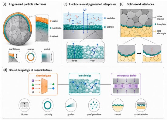
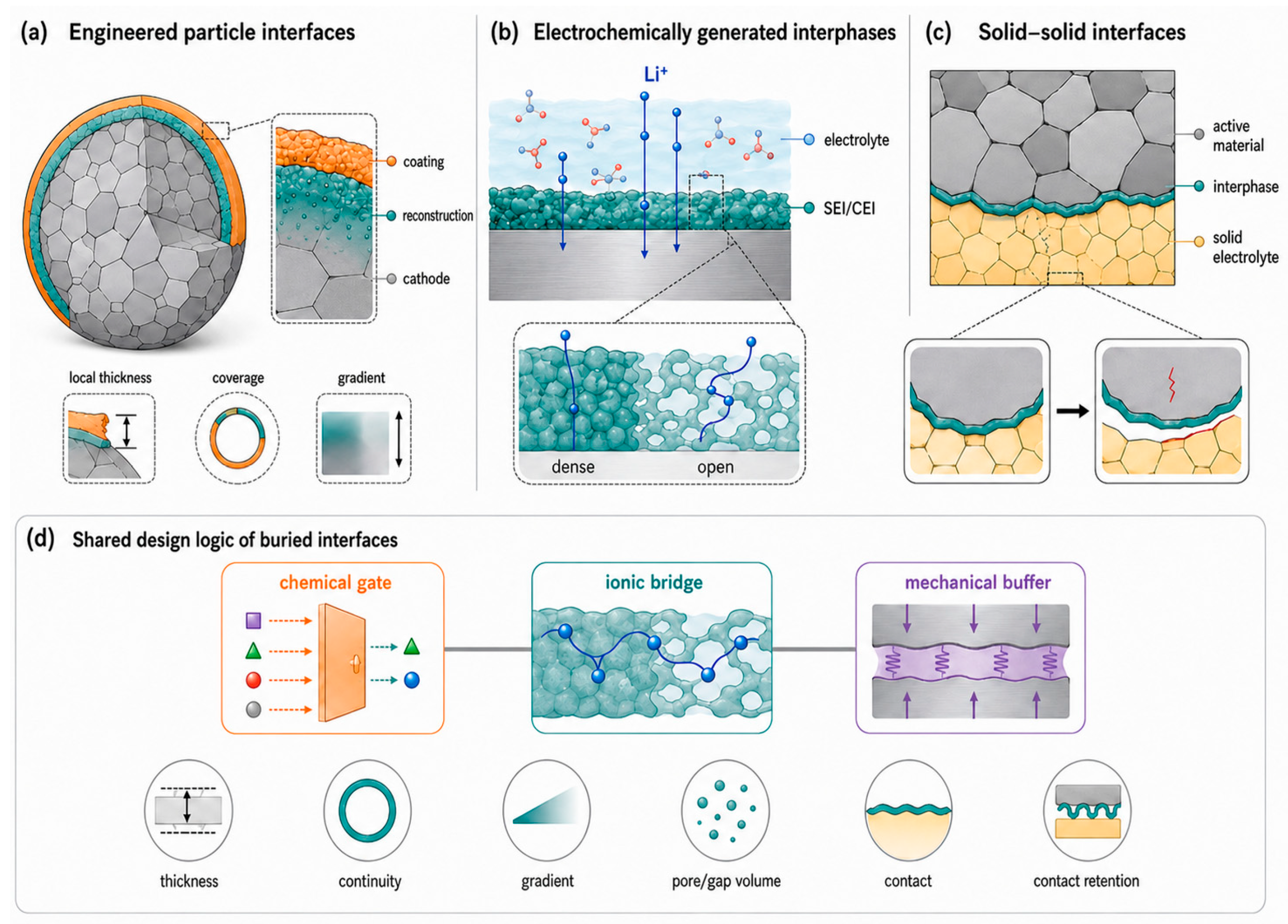
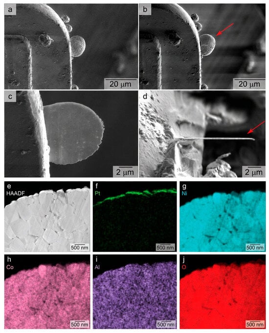
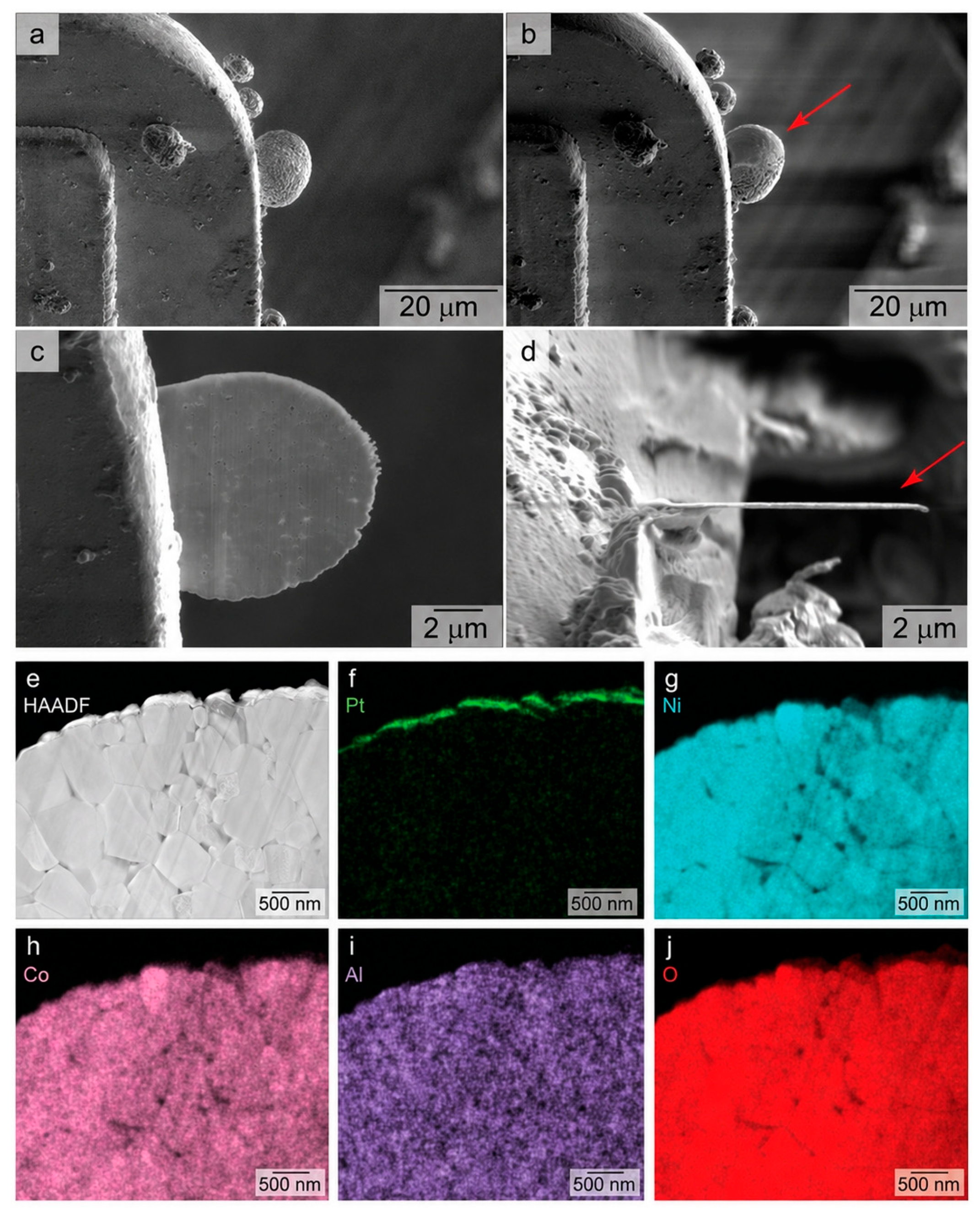
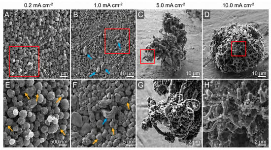
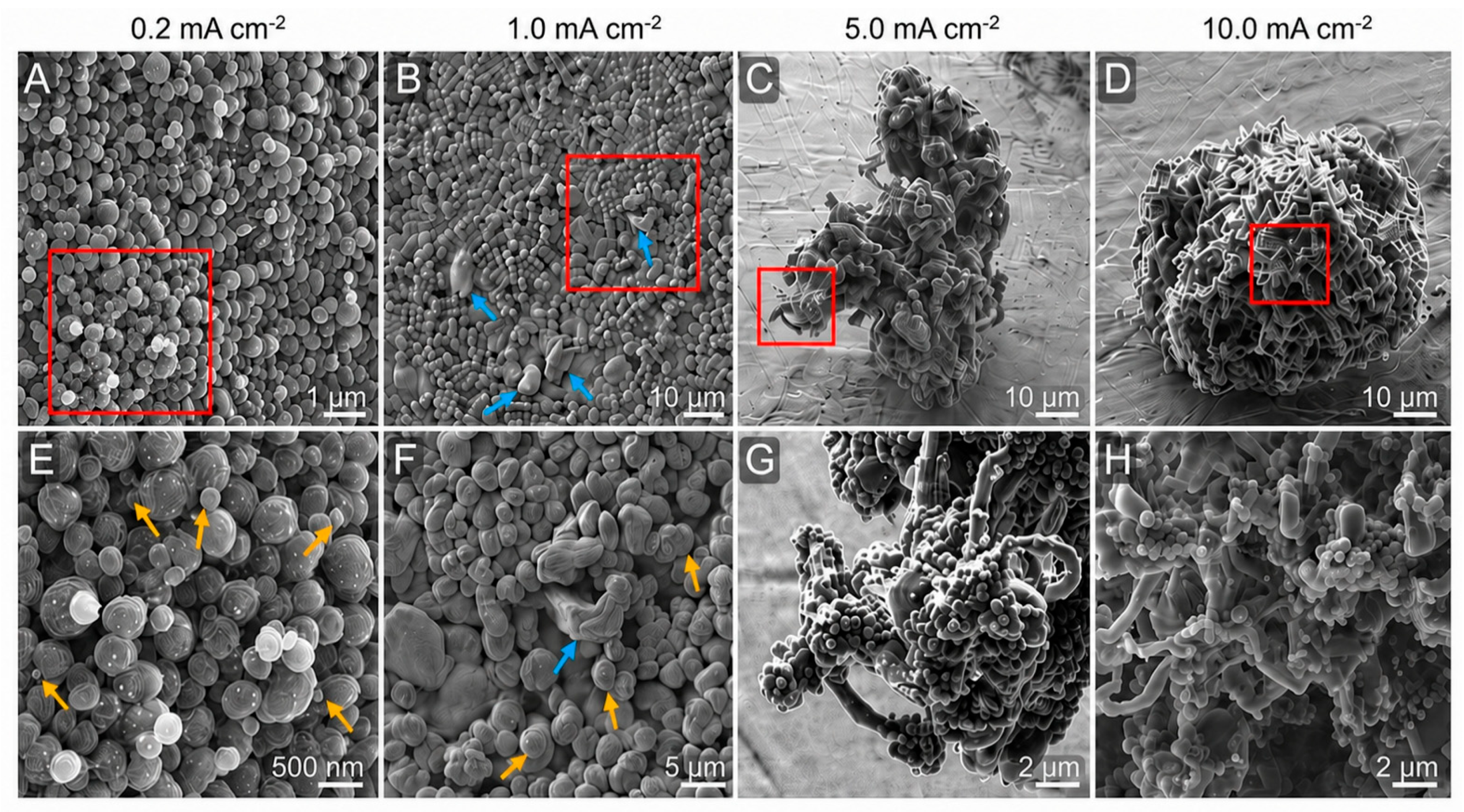
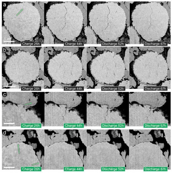
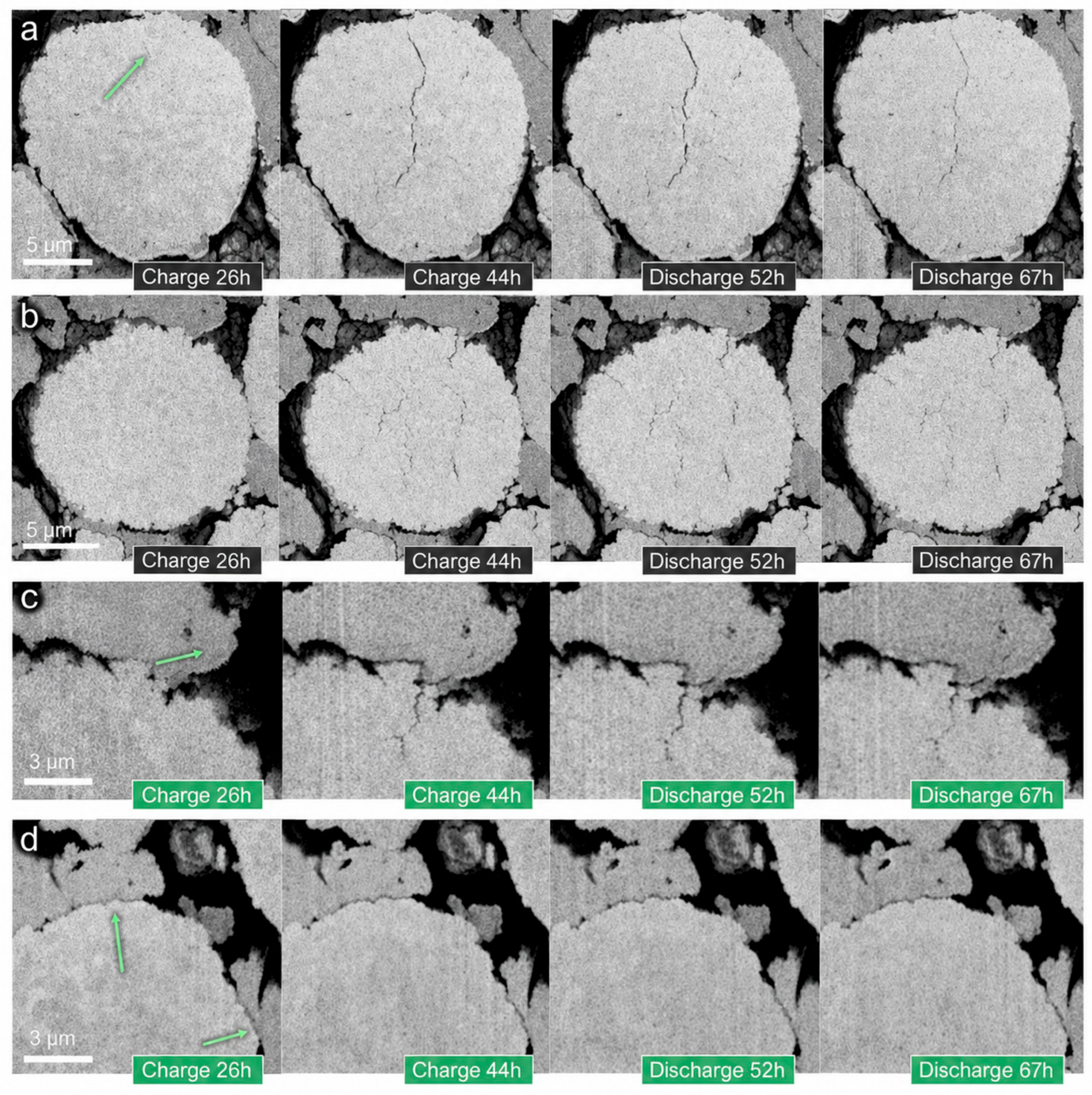
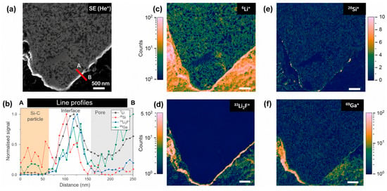
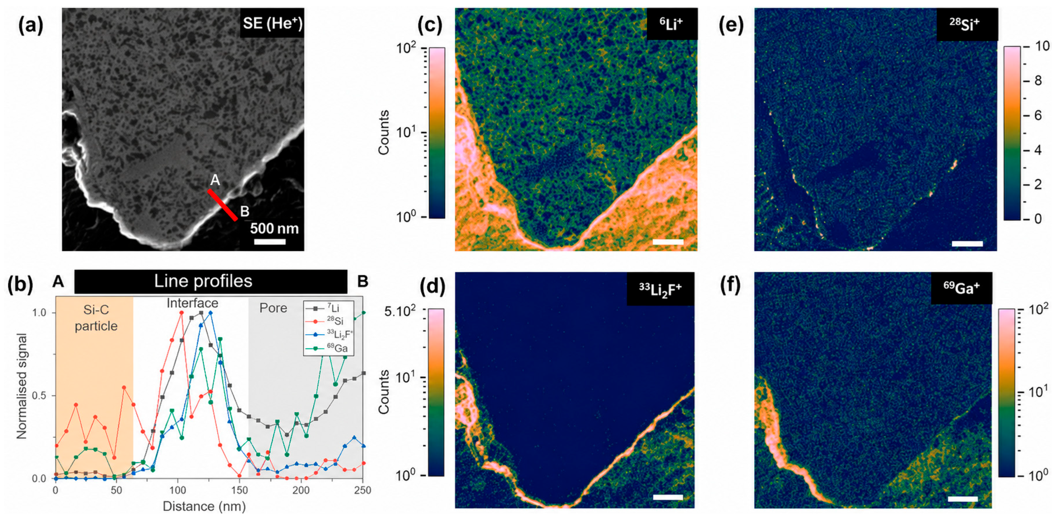

Disclaimer/Publisher’s Note: The statements, opinions and data contained in all publications are solely those of the individual author(s) and contributor(s) and not of MDPI and/or the editor(s). MDPI and/or the editor(s) disclaim responsibility for any injury to people or property resulting from any ideas, methods, instructions or products referred to in the content. |
© 2026 by the authors. Licensee MDPI, Basel, Switzerland. This article is an open access article distributed under the terms and conditions of the Creative Commons Attribution (CC BY) license.