


Abstract
Efficient thermal management is critical for proton exchange membrane fuel cells (PEMFCs). This study develops a bio-inspired active liquid cooling architecture to overcome the limitations of conventional flow channels, where convective heat transfer augmentation significantly increases pressure drop. The proposed configuration adheres to constructal theory and Murray’s law. A three-dimensional conjugate heat transfer model was formulated to evaluate the thermo-hydrodynamic performance against parallel and serpentine flow channels. Under identical conditions, the proposed configuration exhibits superior thermal uniformity and hydrodynamic behavior, alongside minimized parasitic pumping power. At an inlet Reynolds number (Re) of 400, this configuration stabilizes the average bipolar plate temperature at 349.63 K. It reduces the index of uniform temperature (IUT) to 1.49 K, representing a 52.8% thermal uniformity improvement over the parallel flow channel. Furthermore, at an inlet Re of 600, the overall pressure drop is restricted to 68.44 Pa, reducing the single-plate parasitic pumping power to 1.27 × 10⁻⁴ W, which represents reductions of 93.5% and 12.5% relative to the serpentine and parallel flow channels, respectively. This study provides an alternative architectural scheme for the design of active liquid cooling flow channels in PEMFCs.
1. Introduction
Proton exchange membrane fuel cells (PEMFCs) have garnered significant attention as clean energy conversion devices due to their zero emissions and high energy density [1,2,3,4]. During PEMFC operation, a substantial portion of the chemical energy in the fuel is converted to waste heat. At 0.74 V, which is half the thermoneutral voltage, heat generation accounts for 50% of the total energy. Practical PEMFCs typically operate at lower voltages to achieve higher current densities, thereby generating an even greater proportion of waste heat. Inadequate heat dissipation induces thermal accumulation and elevated stack temperatures, accelerating irreversible membrane dehydration and catalyst degradation, ultimately compromising cell durability [5,6]. Conversely, overcooling suppresses the electrochemical reaction kinetics, deteriorating the overall energy conversion efficiency [7,8]. Consequently, efficient thermal management is essential for stable PEMFC stack operation. Over the past two decades, extensive research has investigated the three-dimensional temperature distribution within PEMFCs and stacks. Cooling channels are typically assumed to provide ideal isothermal conditions. However, real-world operations exhibit complex thermal gradients. This discrepancy highlights a critical need for more precise temperature control. It is therefore vital to evaluate the isothermal deviation of individual cooling channels relative to the overall temperature distribution. Such evaluations significantly enhance the current understanding of thermal gradients and local hot spots [9,10]. To confine the operating temperature within a stringent range, active thermal management systems equipped with liquid cooling flow channels have become standard configurations for high-power PEMFC stacks, where the flow channel configuration directly dictates the fluid distribution mechanism and convective heat transfer performance [11].
In conventional engineering applications, parallel and serpentine flow channels are widely recognized as the most fundamental configurations. Existing studies demonstrate that, given identical operating conditions, the enhanced thermal management capacity of the serpentine flow channel over the parallel design comes at the inevitable expense of an elevated pressure drop [12,13]. Consequently, optimization efforts have predominantly targeted the modification of geometric configurations and operating conditions. From the perspective of structural modification, inducing secondary flows to disrupt the thermal boundary layer has proven to be a highly effective strategy. For instance, the series of studies by Huang et al. substantially intensified convective heat transfer by strategically modifying the channel geometry—either by introducing transverse interconnects into the sidewalls [14] or by embedding variable-spacing obstacles within the flow path [15]. However, the cooling effectiveness of such flow-disrupting configurations is highly dependent on their spatial arrangements and operating fluid velocities. To alleviate the severe flow resistance penalty inherent in complex channel designs, Wang et al. [16] employed multi-objective optimization coupled with inlet/outlet flow arrangements, achieving a preliminary compromise between temperature uniformity and pressure drop. In terms of operating condition regulation, Gonzalez-Moran et al. [17] indicated that elevated coolant flow rates and superior bipolar plate thermal conductivity are beneficial for the temperature control of the membrane electrode assembly. Furthermore, regarding coolant selection, ethylene glycol mixtures, despite their marginally inferior heat dissipation capacity, present distinct advantages for cold-environment applications. Khoshvaght-Aliabadi et al. [18] proposed supercritical carbon dioxide (sCO2) as a novel coolant for cooling plates, demonstrating that sCO2-based systems outperform conventional devices by simultaneously augmenting the heat absorption rate and reducing pumping power consumption. Although previous optimization strategies based on classical architectures improve thermal distribution within the stack, most current designs evaluate heat transfer augmentation and hydrodynamic resistance independently. Consequently, these designs face an intrinsic trade-off between thermal dissipation and hydrodynamic friction, which limits the overall thermo-hydraulic performance.
Conventional flow channel designs face inherent performance bottlenecks. Researchers have therefore shifted their focus toward naturally evolved mass transport networks. Nature-inspired flow fields have undergone extensive investigation and validation. This is particularly evident in reactant gas feed channels [19]. For instance, recent studies integrated topology optimization and Murray’s law to develop biomimetic cathode gas flow fields [20]. These specific designs significantly enhance reactant diffusion and minimize fluid resistance. Similarly, bio-inspired intersecting-leaves gas flow fields optimize oxygen distribution uniformity [21]. They also reduce pressure drops compared to traditional configurations. While bio-inspired architectures have demonstrated significant efficacy in gas feed channels, their application to active liquid cooling systems remains limited. Both reactant mass transport and liquid thermal management depend fundamentally on optimized fluid distribution networks. Consequently, researchers have extended the bio-inspired design paradigm to cooling systems, targeting thermo-fluidic allocation in high-power stacks. By mimicking natural topological architectures such as plant venation, these channels offer a geometric mechanism to reconcile the intrinsic trade-off between thermal management and hydrodynamic resistance.
Driven by this specific necessity, recent studies have begun to explore bio-inspired configurations for active liquid cooling. For instance, Liu et al. [22] demonstrated that integrating leaf-inspired morphologies with streamlined profiles in cold plate designs not only yields superior temperature uniformity but also drastically curtails pressure loss. Zhang et al. [23] developed a composite biomimetic leaf-vein fin cooling plate. This design reduced the pressure drop and augmented convective heat transfer, achieving a 136% enhancement in integrated thermo-hydraulic performance. Additionally, Fan et al. [24] designed a liquid cooling plate featuring a bio-inspired fishbone architecture; their results indicated that the single-inlet-double-outlet configuration achieves optimal cooling efficacy, effectively balancing heat dissipation and pressure drop. Similarly, Wang et al. [25] proposed a bio-inspired spider-web cooling channel and conducted orthogonal parameter optimization, revealing the dominant role of channel width in governing heat transfer performance. However, the majority of existing bio-inspired flow channel designs focus on macroscopic morphological mimicry. These designs lack rigorous theoretical underpinnings regarding the geometric evolution of microscopic bifurcation nodes and channel characteristic dimensions.
To address these limitations, this study develops a novel three-dimensional bio-inspired cooling flow channel for PEMFCs, fundamentally underpinned by constructal theory [26] and Murray’s law [27]. Unlike previous studies that rely primarily on isolated geometric modifications or operating condition tuning, the present work achieves a rigorous synergistic integration between macroscopic network configuration and microscopic characteristic dimensions. Macroscopically, the channel network adheres to the space-filling principle to guarantee uniform heat extraction across the active area; microscopically, the equivalent hydraulic diameters of adjacent bifurcation levels are guided by the principle of minimum work dictated by Murray’s law.
2. Methods
2.1. Physical Model and Bio-Inspired Flow Channel Design
This study establishes a three-dimensional numerical simulation model to accurately evaluate the thermal and hydrodynamic behavior of the bipolar plates with integrated cooling channels in PEMFCs. The numerical computation domain consists of the solid substrate of the bipolar plates and the liquid flow channels embedded within them. Unlike heat dissipation designs that rely on external liquid cooling plates, this study integrates the cooling channels directly into the bipolar plates. This integrated configuration optimizes stack compactness and enhances interfacial heat transfer. Simultaneously, deionized water with good electrical insulation properties is adopted as the cooling medium to avoid the risks of electrochemical short circuits during PEMFC stack operation.
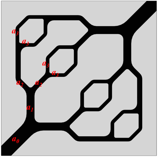
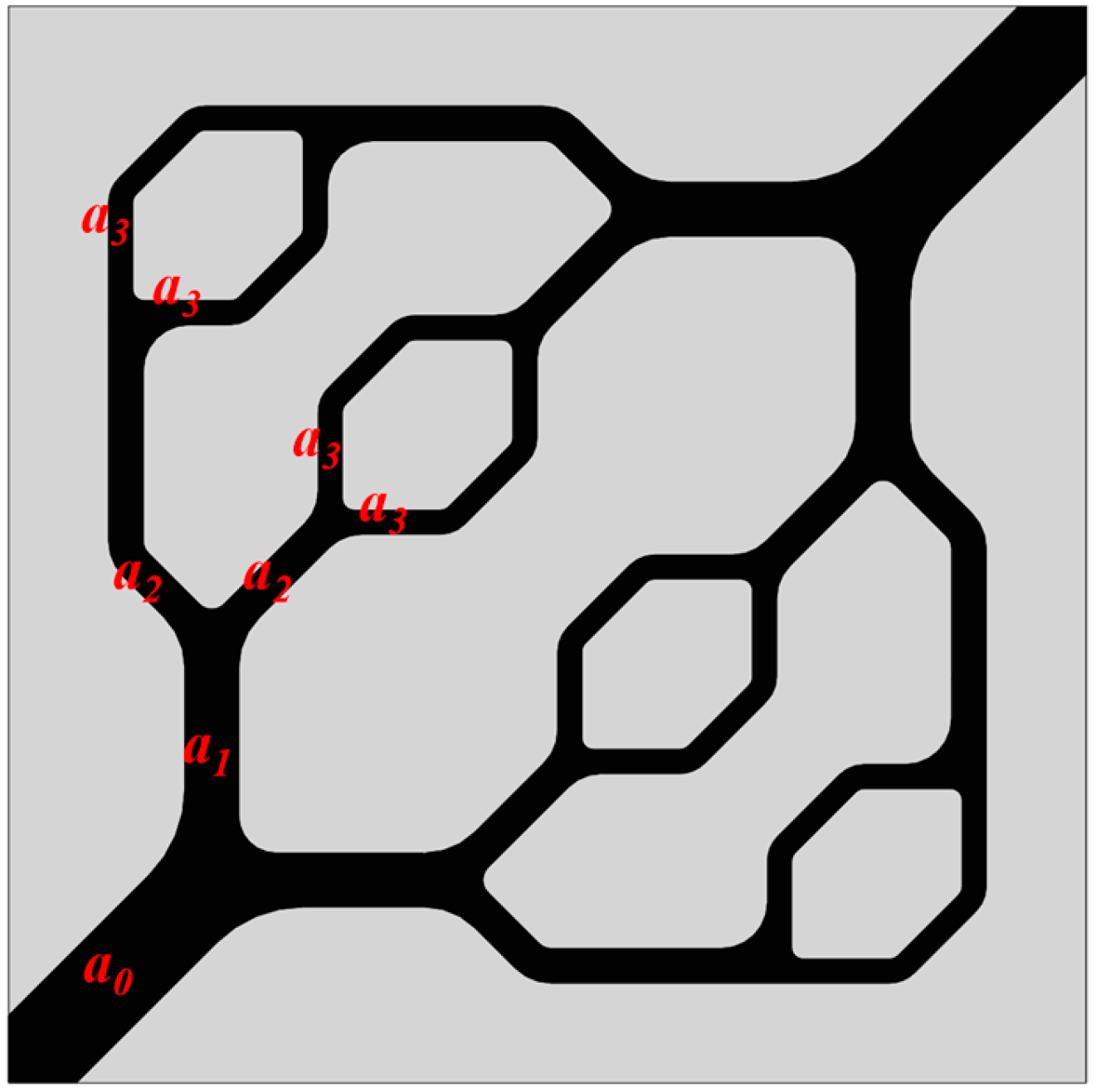
Traditional parallel flow channels often suffer from flow maldistribution and insufficient convective heat transfer. While serpentine flow channels can provide high heat transfer intensity, their flow resistance increases significantly with the path extension, often leading to substantial parasitic power consumption. This study aims to improve the net output efficiency of the PEMFC stack system by reducing parasitic power consumption. To achieve this, it is necessary to maintain excellent heat dissipation performance while decreasing pressure drop losses. Therefore, based on constructal theory and Murray’s law, the flow channel configuration within the cooling plate is optimized into a self-similar hierarchical branching network. This innovative design synergistically ensures overall system heat dissipation while decreasing flow resistance. The designed flow channel unit shapes and the naming of each branch are shown in Figure 1.
Figure 1.
Display image of bio-inspired flow channel unit, the red labels (a0, a1, etc.) represent the flow channels at different hierarchical levels.
This study employs a symmetric binary tree branching network to guide the macroscopic architecture and spatial expansion. This design is based on the space-filling theory proposed by Adrian Bejan. Specifically, every two lower-level channels are symmetrically connected to one higher-level channel. Additionally, the length ratio of the adjacent two-level channels satisfies the following classical geometric constraints:
where Li and Li+1 denote the lengths of the higher-level main channel and the lower-level branch channel, respectively. This constraint ensures that the cooling channel network achieves optimal space filling and geometric coverage of the bipolar plate, and maintains the geometric similarity of each level of constructal elements.
Building upon this macroscopic configuration, the characteristic dimensions of the channels at the bifurcation nodes are determined using Murray’s law, which is considered the optimal geometric criterion for fluid transport systems operating under conditions of minimum power. This law states that for channels with circular cross-sections, the diameters of the main channel and its branches must satisfy a cubic relationship:
where d0 and dj denote the equivalent diameters of the main channel and the j-th daughter branch. n represents the number of branches at a single bifurcation node, which is set to 2 in this study. Therefore, the relationship between the diameters of adjacent channels in the proposed flow channel design is as follows.
In the proposed symmetric binary tree flow channel, the equivalent diameter ratio between adjacent levels, i and i + 1, can be simplified as follows:
Constrained by the practical manufacturing processes of bipolar plates, the cooling channels typically adopt a rectangular cross-section [28]. Its equivalent diameter Dh is given by:
where w and h represent the width and depth of the flow channel at a given hierarchical level, respectively.
The channel depth is kept constant across all levels. Meanwhile, the width of each sub-channel is adjusted to ensure the equivalent hydraulic diameters follow Murray’s law. This design allows the branching network to distribute flow uniformly and minimize overall flow resistance.
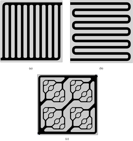
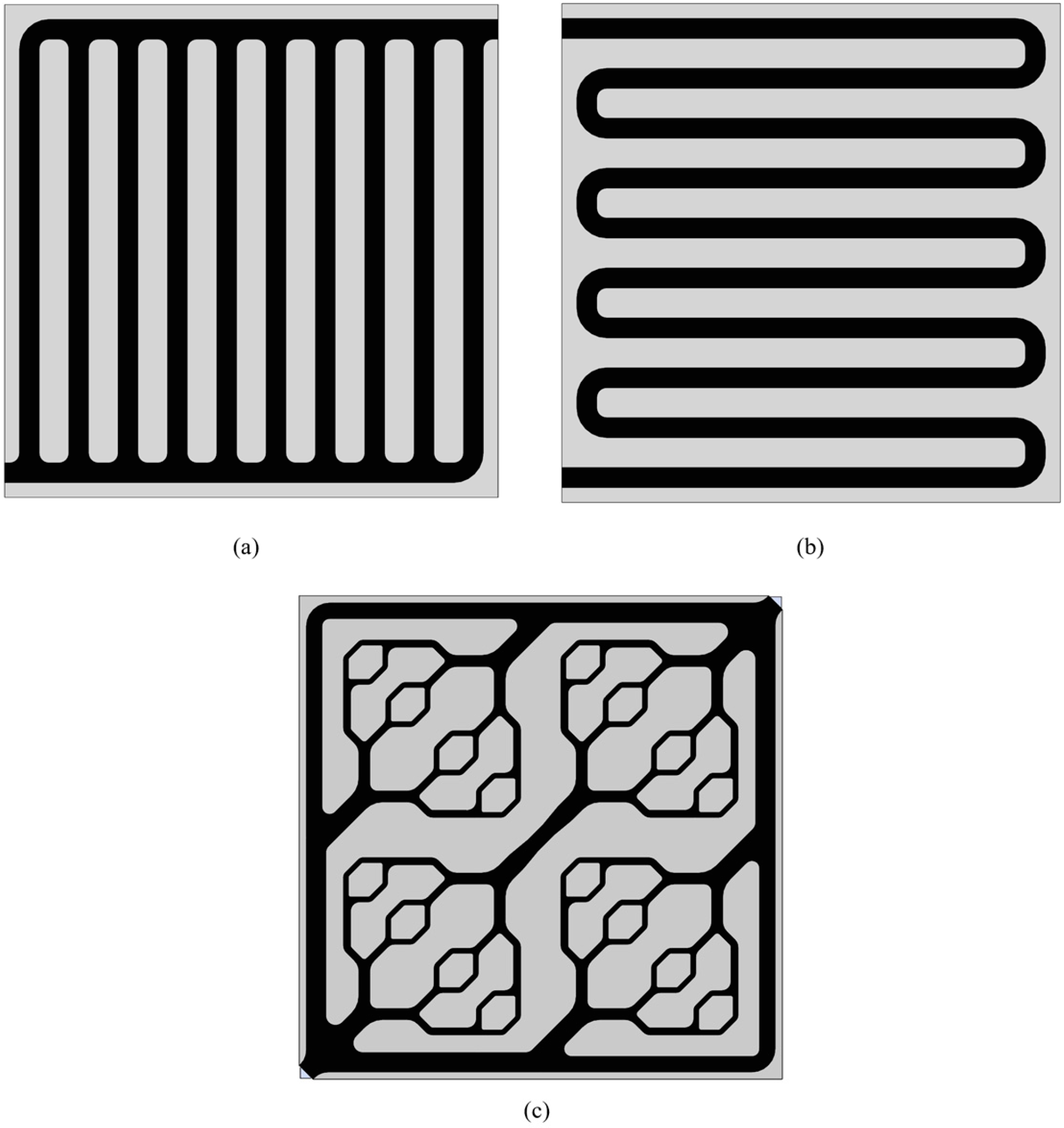
To systematically evaluate the performance of the proposed bio-inspired flow channel, conventional parallel and serpentine flow channels were established as benchmark models for comparative analysis; all geometric configurations are depicted in Figure 2. To ensure a fair thermo-fluid comparison, the inlet cross-sectional area is identical across all three models. Table 1 details other key geometric parameters, such as total coolant volume, effective heat-transfer area, and total wetted area. As shown in Table 1, the bio-inspired channel features a smaller effective heat-transfer area and coolant volume compared to the parallel and serpentine channels, while their total wetted areas remain comparable. Conventionally, a reduced heat-transfer area and fluid capacity would degrade thermal performance. Nevertheless, the proposed bio-inspired design aims to overcome this conventional limitation. This study hypothesizes that enhanced thermo-hydraulic performance does not strictly rely on a large fluid volume. Instead, it can be achieved through the synergistic outcome of both the constructal branching topology and the revised geometric dimensions. Additionally, to conform to the actual bipolar plate machining process and eliminate unnecessary local pressure drops, all flow channel bends were smoothly filleted. The specific geometric dimensions of each model on the bipolar plate are detailed in Table 1.
Figure 2.
Geometric configurations of different channels: (a) Parallel flow channel. (b) Serpentine flow channel. (c) Bio-inspired flow channel.
Table 1.
Geometric dimensions of different channels.
2.2. Governing Equations
Given the vertical orientation of the PEMFC stack and its relatively narrow operating temperature window, the following fundamental assumptions are adopted for the three-dimensional conjugate heat transfer and fluid flow model [29,30]. These assumptions are formulated to strike an optimal balance between computational efficiency and numerical fidelity:
- The coolant flow is assumed to be steady, incompressible, and laminar.
- The fluid flow at the inlet is assumed to be fully developed.
- All solid–fluid interfaces are assumed to satisfy the no-slip condition and to be impermeable to mass transfer.
- The heat source distribution on the electrochemical surface is uniform and constant during steady-state operation of the PEMFC.
- Radiation heat exchange between the cold plate and its surroundings is neglected.
- Considering the effect of buoyancy caused by gravity on heat transfer, the Boussinesq approximation is utilized. Specifically, the fluid is treated as strictly incompressible in the continuity equation, while temperature-dependent density variations are applied exclusively to the body force term in the momentum equation. All other thermophysical parameters are considered constant within the target temperature range.
Based on the aforementioned physical simplifications and conjugate heat transfer mechanisms, the governing equations describing mass conservation, momentum transfer, and energy balance within the computational domain are as follows:
- Continuity equation
- 2.
- Momentum conservation equation
- 3.
- Energy equation of fluid domain
- 4.
- Thermal conduction equation in solid domain
2.3. Mechanisms of Heat Generation and Thermal Balance
During operation, the thermal management of PEMFC stacks is dictated by a dynamic equilibrium between electrochemical heat generation and convective heat dissipation. Quantifying electrochemical heat generation and macroscopic energy balance is necessary to define the thermal boundary conditions.
2.3.1. Electrochemical Heat Generation Theory
During the conversion of hydrogen’s chemical energy into electrical energy, PEMFCs generate heat. The total heat generation rate comprises two primary components [31,32]. The first component is irreversible heat, which arises from activation, ohmic, and concentration overpotentials. The second is reversible entropic heat, which results from the entropy change during the electrochemical reaction [11,33]. The theoretical total heat generation rate Qgen of a cell can be quantitatively expressed as the product of the actual operating current and the difference between the thermoneutral voltage Eth and the actual operating voltage Vcell.
where I represents the actual operating current of the PEMFC. Eth is defined as the theoretical voltage at which all the enthalpy change in the hydrogen oxidation reaction is converted into electrical energy.
To meet the requirements of the numerical calculation of three-dimensional conjugate heat transfer, the total heat generation of the PEMFC is equivalently mapped as a surface heat source applied to the active area A at the interface between the solid bipolar plate and the membrane electrode assembly. This provides a rigorous physical input basis for the thermodynamic boundary conditions in the numerical simulation. Its average surface heat flux is calculated as follows:
where i is the current density expressed in A/cm2.
2.3.2. System Thermal Balance and Cooling Requirements
From a macroscopic thermal management perspective, the total heat generated inside the fuel cell and the heat dissipated through each path must satisfy the steady-state thermal balance equation:
where Qcool represents the heat extracted by the coolant via forced convection. Qre stands for the heat carried away by the reacting gases, which includes unreacted hydrogen, air, and water vapor. And Qamb is the heat lost from the fuel cell surface to the surrounding environment through natural convection and radiation. In practical engineering, since Qre and Qamb constitute a negligible fraction of the total heat dissipation, the active liquid cooling system must be capable of dissipating the majority of the heat load to ensure that the fuel cell does not experience thermal degradation at high current densities.
To ensure uniform bipolar plate temperatures, the temperature rise between the coolant inlet and outlet must remain within a safe margin, which is typically under 10 K. Therefore, the required mass flow rate of the coolant flowing through the cooling plates must satisfy the following relationship with the heat absorption capacity of the system:
where cp,f is the isobaric specific heat capacity of the liquid cooling medium. Tin and Tout are the inlet and outlet temperatures of the cooling water, respectively.
This macroscopic thermal equilibrium mechanism not only establishes a benchmark for setting the characteristic inlet Re of the fluid inlet in the CFD model, but also provides a theoretical basis for subsequent evaluation of the unique advantages of the Murray’s law bio-inspired channel in reducing the parasitic power of the pump.
The key thermophysical properties of the matrix material and liquid working fluid used in the numerical simulation are summarized in Table 2.
Table 2.
Thermophysical property parameters of each phase material in the calculation model.
2.4. Performance Evaluation Indicators
To quantitatively compare the heat transfer and hydrodynamic performance of cooling flow channels with different architectures, this study introduces the following three key indicators as the basis for subsequent performance analysis.
- (1)
- The Index of Uniform Temperature
The temperature uniformity of the bipolar plates in a PEMFC directly affects the membrane’s durability and the local electrochemical reaction kinetics. Therefore, this study employs the Index of Uniform Temperature (IUT) to characterize the thermal management efficacy of PEMFCs [34]. Physically, the IUT evaluates the area-weighted average deviation of local surface temperatures relative to the overall mean bipolar plate temperature, and its unit is Kelvin (K). A lower IUT indicates a more uniform temperature distribution and fewer hot spots, which is more conducive to extending the lifespan of the PEMFC stack.
where T and Tavg are the temperature and average temperature of the bipolar plate-membrane contact surface, respectively.
- (2)
- Pressure Drop
The hydrodynamic resistance of fluid passing through the cooling plate is quantified by the total pressure difference between the inlet and outlet. It is the most intuitive indicator for evaluating the hydrodynamic performance of the flow channel, and its calculation formula is:
where Pin,avg and Pout,avg are the average pressures at the inlet and outlet sections of the coolant, respectively.
- (3)
- Parasitic Pumping Power
In the PEMFC systems, the power consumed to drive the active liquid cooling cycle inevitably compromises the net output power of the entire PEMFC stack system [35,36]. The parasitic power of the water pump Ppump is introduced to convert the hydrodynamic pressure drop into single-cell energy loss and verify the energy-saving advantages of bio-inspired flow channels. This parameter represents the actual input power consumed by the pump. Its theoretical model is defined as follows:
where ρf stands for the density of the coolant, and ηpump denotes the equivalent mechanical efficiency of the coolant pump. This metric serves as a key indicator for evaluating the advantage of bio-inspired channels in reducing parasitic pumping power at the single-plate level.
2.5. Model Validation and Grid Independence Test
2.5.1. Model Validation
To validate the present three-dimensional conjugate heat transfer model, the simulated results were compared against experimental data for a parallel cooling channel reported in the literature [37]. The geometric dimensions, material properties, and thermal boundary conditions in the simulation were configured to match the referenced experimental setup.
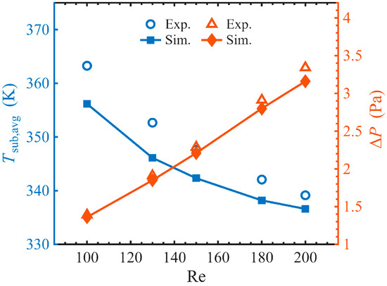
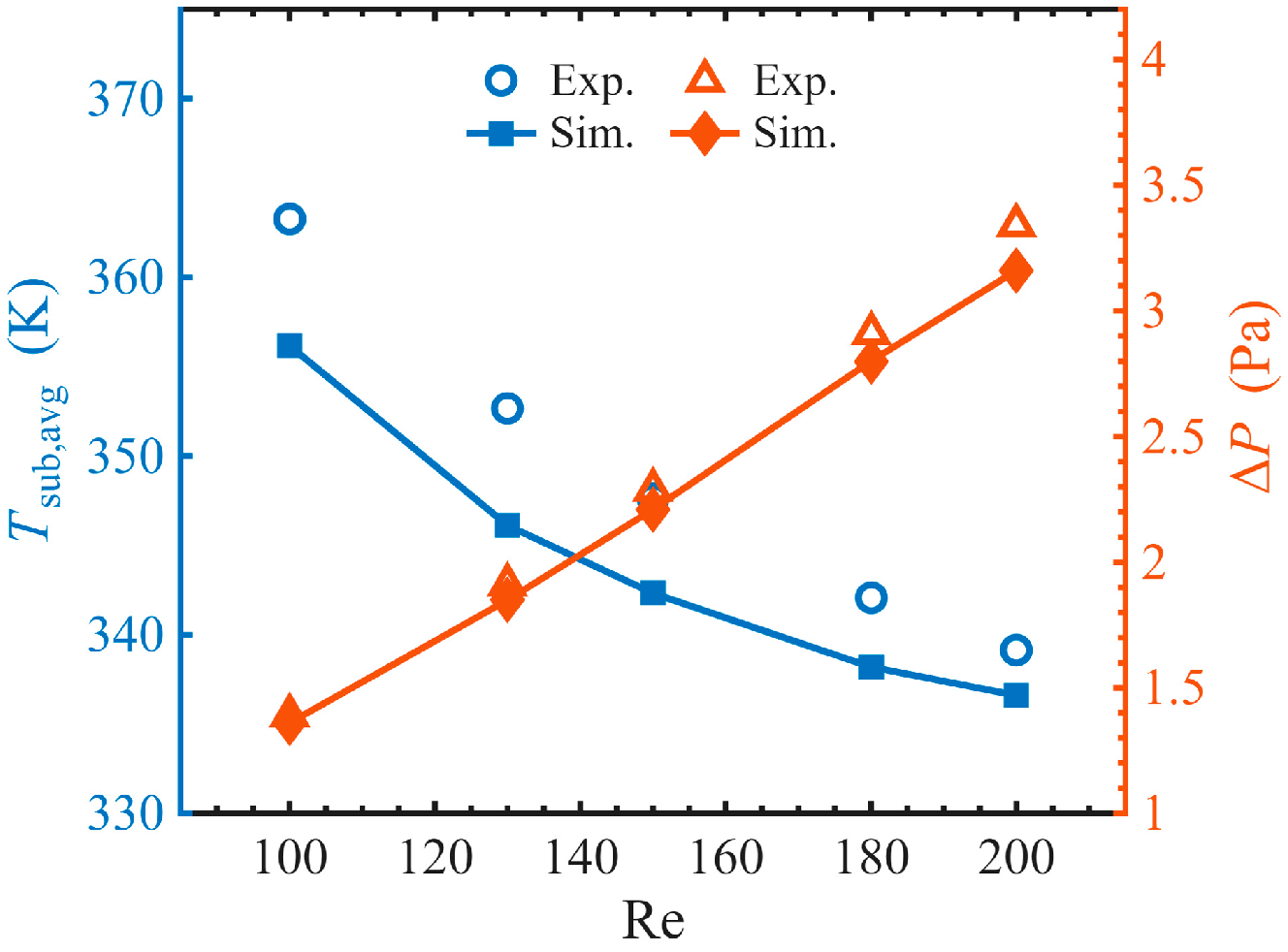
To ensure a comprehensive validation, both the average surface temperature and the pressure drop were evaluated across various inlet Reynolds numbers. As illustrated in Figure 3, the predicted thermal and hydrodynamic trends show favorable agreement with the experimental measurements. Specifically, the maximum relative errors between the numerical calculations and the experimental data are 1.95% for the surface temperature and 5.39% for the pressure drop.
Figure 3.
Model validation.
These results demonstrate that the numerical method and boundary assumptions adopted in this study offer high accuracy in predicting both the thermal and hydrodynamic behaviors of the PEMFC cooling channels. Consequently, this model provides a solid and reliable analytical basis for the subsequent performance evaluation.
2.5.2. Grid Independence Test
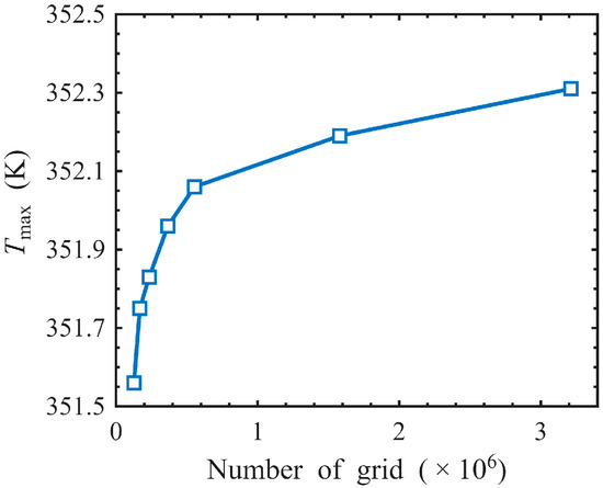
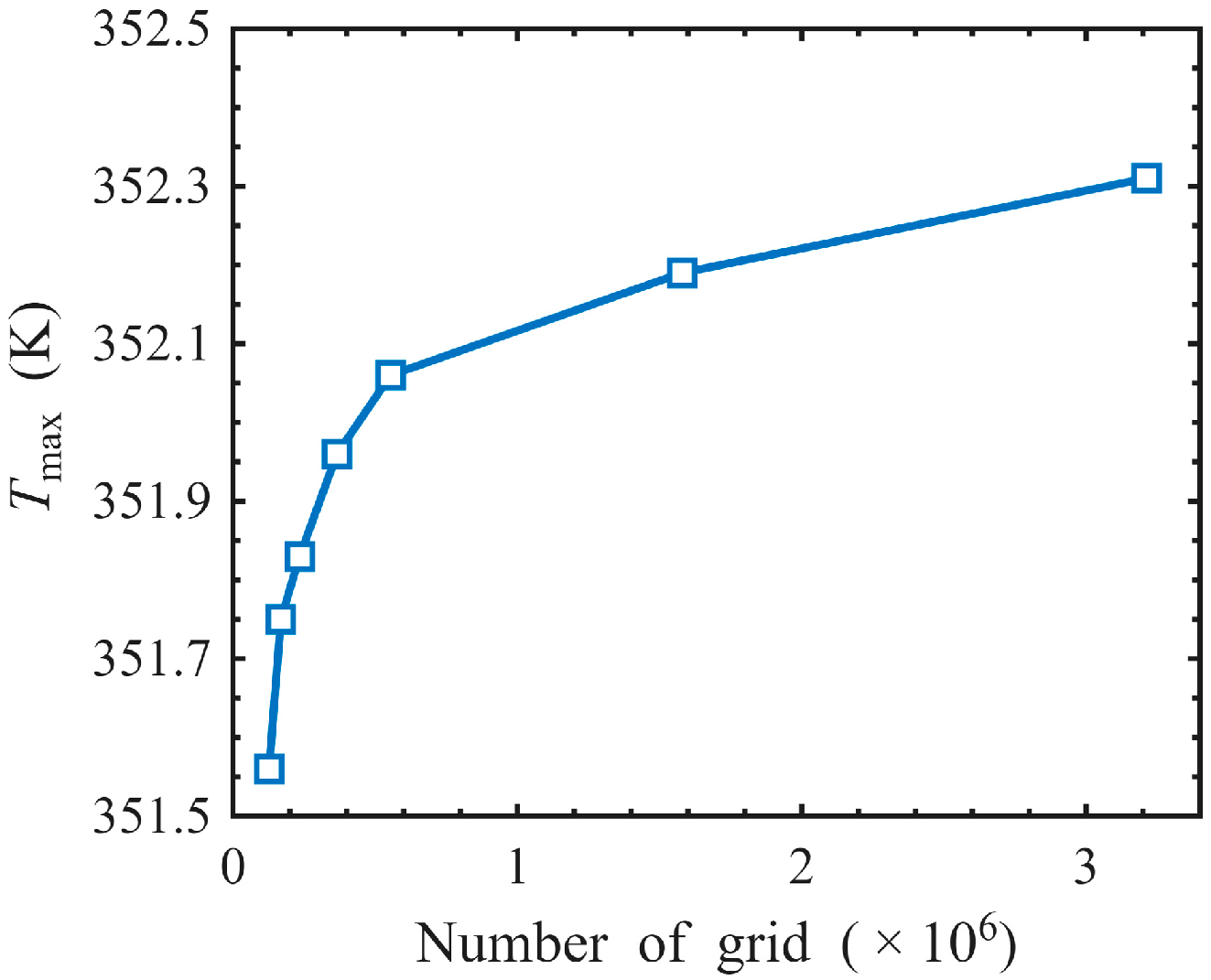
To eliminate the influence of grid density on numerical simulation results, this study verified the grid independence of several cooling channels. Since this study focuses on the thermal management performance, the maximum plate temperature Tmax was regarded as the primary monitoring metric. As illustrated in Figure 4, the calculated maximum temperature gradually stabilized as the grid element count increased. When the number of grid elements increased from 1.580 million to 3.212 million, the calculated value of Tmax only slightly increased from 352.19 K to 352.33 K. The relative error caused by this difference was only 0.04%, indicating that the numerical solution was independent of the mesh resolution at this point. Furthermore, based on the same principle, grid independence verification was also performed on parallel and serpentine channels. Considering both the accuracy and computational cost of numerical calculations, the final grid scheme determined in this study is shown in Table 3.
Figure 4.
Grid independence test based on the maximum plate temperature.
Table 3.
Number of grids for the different flow channel configurations.
3. Results and Discussion
3.1. Thermodynamic and Heat Transfer Performance Evaluation
3.1.1. Macroscopic Quantification of Ultimate Heat Dissipation Capacity and Temperature Uniformity
Prior to presenting the parametric analysis, it is essential to establish the theoretical foundation of the primary independent variable utilized in this study: the inlet Re. Re is a dimensionless quantity that characterizes the ratio of inertial forces to viscous forces within the fluid, essentially dictating the flow regime. In the present numerical model, the inlet Re is mathematically defined as:
where uin and Dh,in denote the coolant inlet velocity and the equivalent hydraulic diameter at the inlet manifold, respectively. Generally, the flows are universally considered laminar when the Reynolds number falls below 2300.
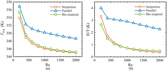
To comprehensively analyze the evolution of different flow channels over a wide velocity range, the inlet Re was initially investigated over a parametric range of 200 to 2000. An inlet Re exceeding 600 provide limited cooling enhancement but significantly increase the parasitic load. Therefore, this range is considered to have low practical value in the operation and application of fuel cell systems. Based on the full-range trend analysis, this section focuses on a practical engineering velocity regime defined by an inlet Re up to 600. The analysis is categorized into three conditions: a low-velocity cooling condition at an inlet Re of 200, a nominal design condition at 400, and a high-velocity cooling condition at 600.
The electrochemical activity and durability of PEMs are extremely sensitive to temperature. In practical engineering, the operating temperature of a PEMFC stack must be strictly maintained below 353.15 K. As shown in Figure 5, under low flow rate conditions, the global convective heat transfer capacity is inadequate. Consequently, the average temperatures of the parallel flow channel and the bio-inspired flow channel reached 356.85 K and 355.38 K, respectively, both exceeding the safety threshold of 353.15 K. Driven by a higher flow velocity that enhances forced convection, the single serpentine channel maintains a temperature of 353.93 K. However, under identical conditions, the IUT of the parallel flow channel reaches 3.99 K, indicating a high risk of localized hot spot formation on the electrode surface.
Figure 5.
Variation trends of average temperature and index of uniform temperature with inlet Re: (a) Average temperature. (b) Index of uniform temperature.
When the flow rate was increased to the nominal design condition, all three flow channels successfully constrained the bipolar plate temperature below the 353.15 K threshold. The serpentine flow channel exhibited stronger heat transfer capacity, with an average temperature of 348.95 K. However, its IUT remained relatively high at 1.72 K. The bio-inspired flow channel showed an advantage in temperature uniformity. At an inlet Re of 400, the bio-inspired channel stabilizes the average temperature at 349.63 K and minimizes the IUT to 1.49 K. The IUT of the bio-inspired flow channel was reduced by 52.8% and 13.5% compared to the parallel flow channel and the single serpentine flow channel, respectively. Furthermore, at the highest practical inlet Re of 600, the cooling capacity of the bio-inspired flow channel further approached that of the serpentine flow channel, with an IUT and average temperature of 1.07 K and 347.81 K, respectively. This indicates that the bio-inspired channel can realize a high degree of synergy between the overall heat dissipation capacity and surface temperature uniformity of the fuel cell.
3.1.2. Evolution of Local Temperature Field and Heat Transfer Mechanism Within the Bipolar Plate
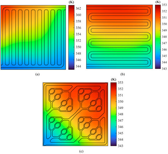
The temperature distribution contour maps of the bipolar plate surfaces with the three types of cooling flow channels at an inlet Re of 400 are presented in Figure 6. The microscopic spatial distributions illustrate the heat transfer mechanisms of different architectures. It should be noted that independent color scales are used for each contour plot. Because the parallel channel’s peak temperature is significantly higher, applying a unified scale would severely compress the visual gradients of the other two channels, thereby obscuring their local thermal distribution details.
Figure 6.
Temperature distribution contour maps of the bipolar plate surfaces with three types of cooling flow channels: (a) Parallel flow channel. (b) Serpentine flow channel. (c) Bio-inspired flow channel.
For the conventional parallel flow channel, as depicted in Figure 6a, although the physical heat transfer path of individual branches is shortened, the system suffers from severe flow maldistribution driven by fluid momentum inertia at the inlet manifold. Propelled by the inlet kinetic energy, most of the coolant flows directly into the branch with the same flow direction as the inlet, leaving the remaining peripheral branches in a state of severe coolant starvation. This flow maldistribution reduces the local convective heat transfer coefficient, causing localized heat accumulation and elevated temperatures in the edge regions. Therefore, its maximum temperature also rises to 361 K. Conversely, as illustrated in Figure 6b, the serpentine flow channel exhibits different thermodynamic characteristics. The high fluid velocity within its narrow channels induces strong convection, maintaining a low global average bipolar plate temperature of 348.95 K. However, owing to its excessively long flow path, the coolant continuously accumulates sensible heat along the trajectory. This continuous heat accumulation gradually reduces the temperature difference between the coolant and the bipolar plates. Consequently, the cooling capacity in the downstream flow channel decreases, causing localized heat accumulation near the outlet.
In contrast, the bio-inspired bifurcation flow channel, as shown in Figure 6c, exhibits distinct advantages in modulating the temperature field, both qualitatively and quantitatively. Although its overall average temperature is slightly higher than that of the serpentine flow channel, the temperature distribution within its bipolar plates demonstrates a high degree of symmetry and uniformity. Quantitatively, its IUT is reduced by 52.8% and 13.5% relative to the parallel and serpentine channels, respectively. This heat transfer performance stems from the multi-level bifurcation network governed by Murray’s law. This configuration enables proportional coolant distribution across the entire active surface of the PEMFC stack. Each branch of the bio-inspired flow channel extracts heat evenly from the surrounding graphite matrix. This distribution mitigates the localized elevated temperatures caused by flow maldistribution in the parallel channel and the extended flow trajectory in the serpentine channel, resulting in improved global temperature uniformity.
3.2. Hydrodynamic Characteristics and Flow Advantages
3.2.1. Evolution Characteristics of Macroscopic Pressure Drop Loss with Operating Conditions
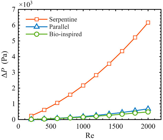
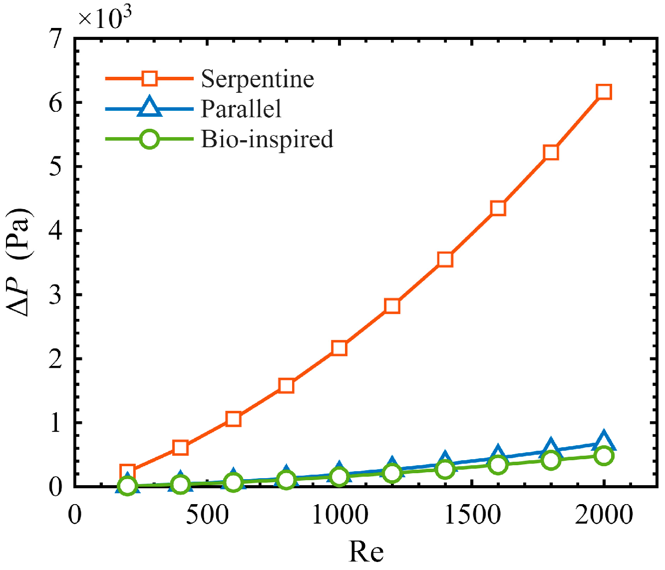
The total flow pressure drop is a critical performance metric for active liquid cooling systems, primarily determining the parasitic pumping power and overall hydrodynamic efficiency. The nonlinear evolution of the macroscopic pressure drop across the three cooling flow channels for inlet Re ranging from 200 to 2000 is depicted in Figure 7. It is clear that the structure of the flow channels has a definitive impact on the overall system pressure drop. Specifically, the pressure drop exhibits a marked increase as the inlet Re exceeds 800. This trend justifies adopting an inlet Re of 600 as the maximum practical test condition.
Figure 7.
Variation in the pressure drop as a function of the inlet Re.
Within the practical operational regime characterized by inlet Re up to 600, traditional parallel flow channels effectively reduce flow resistance through multi-branch diversion. Consequently, at the maximum test condition with an inlet Re of 600, the total system pressure drop is restricted to 78.18 Pa. In contrast, single serpentine flow channels exhibit extremely high flow resistance due to their long, narrow single-channel path and frequent 180° U-turns. For instance, at an inlet Re of 600, the overall pressure drop of the serpentine channel reaches 1059.40 Pa, which is 13.55 times greater than that of the parallel flow channel.
Remarkably, the bio-inspired flow channel maintains the lowest flow resistance throughout the entire range of practical engineering conditions. At an inlet Re of 600, the total pressure drop of the bio-inspired flow channel is only 68.44 Pa. This represents a 93.5% reduction in flow resistance relative to the single serpentine configuration. Moreover, even when benchmarked against the conventional parallel channel—which is inherently characterized by its low flow resistance—the pressure drop of the bio-inspired flow channel is further reduced by 12.5%. This result demonstrates that the bio-inspired configuration network, strictly adhering to Murray’s law, exhibits superior flow resistance reduction capabilities at the macroscopic fluid dynamics level, providing a highly optimized configuration choice for the low-power operation of active liquid cooling systems.
3.2.2. Microscopic Velocity Field Distribution and Hydrodynamic Loss Mechanisms
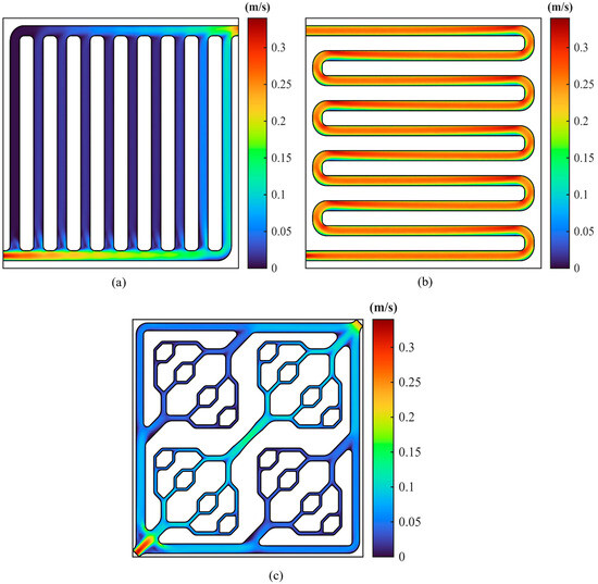
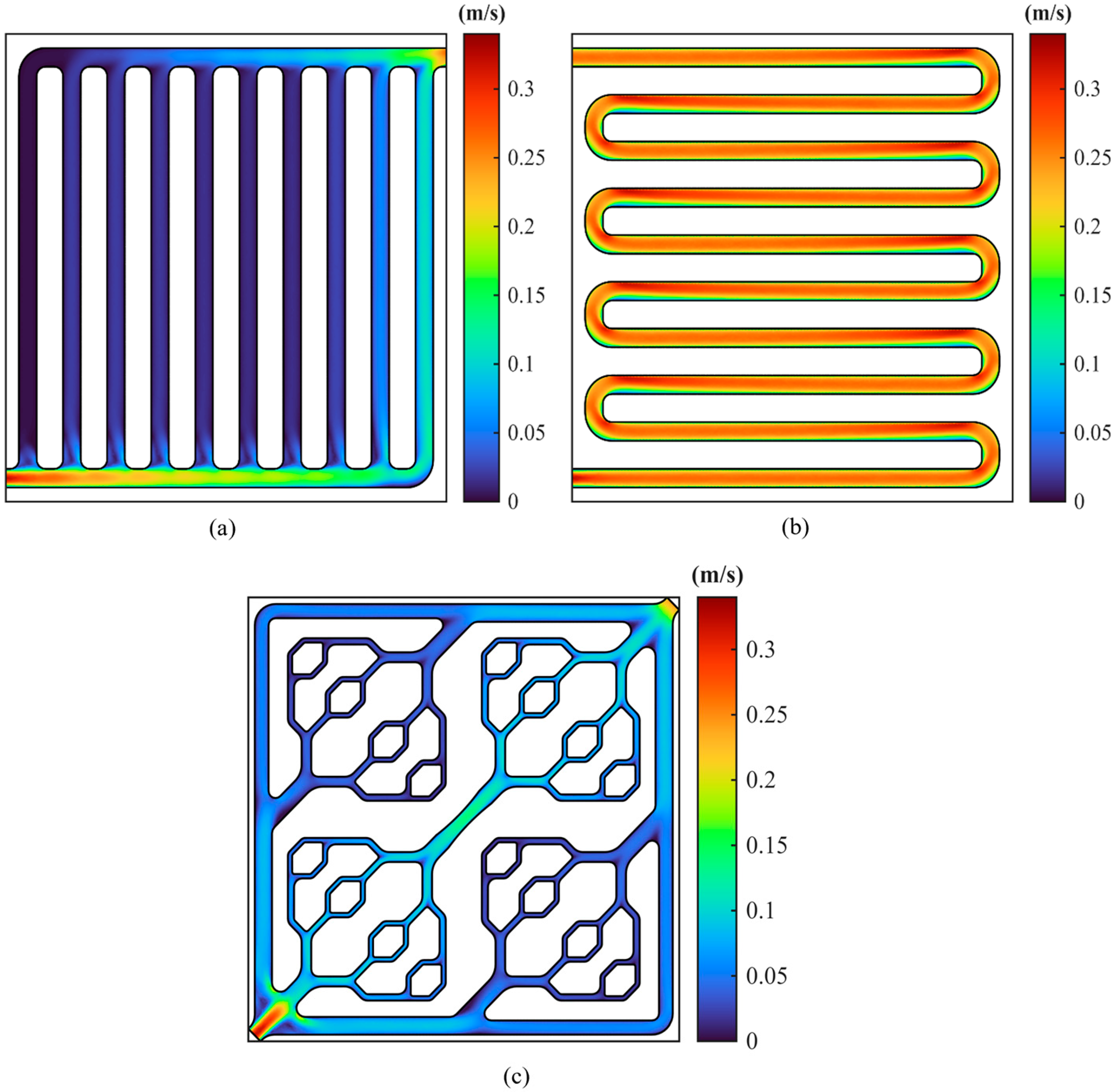
The local velocity distribution contours for the cross-sections of the three cooling flow channels at an inlet Re of 400 are presented in Figure 8. Fundamentally, the flow resistance is governed by the superposition of frictional drag along the fluid trajectory and localized form drag induced by abrupt geometrical transitions. In the conventional parallel flow channel depicted in Figure 8a, the coolant undergoes a sudden expansion in cross-sectional area as it flows into the manifold. Fluid momentum directs the bulk flow into the transverse channels, which causes flow maldistribution across the network. As depicted in Figure 8b, the serpentine channel avoids flow maldistribution. However, the narrow path forces the coolant to maintain high velocities. Furthermore, the continuous 180° turns generate high frictional and local form drag, significantly increasing the total pressure drop.
Figure 8.
Local velocity distribution contours within the fluid domains of the three cooling flow channel configurations: (a) Parallel flow channel. (b) Serpentine flow channel. (c) Bio-inspired flow channel.
Notably, as illustrated in Figure 8c, the bio-inspired bifurcation flow channel designed in this study largely avoids the aforementioned hydrodynamic defects due to its inherent geometric advantages. Its velocity contour plot demonstrates that at the bio-inspired hierarchical bifurcation nodes, the streamlines of the working fluid can smoothly conform to the wall surface, achieving efficient momentum distribution between the parent and daughter branches. This progressive bifurcation network effectively avoids the high-resistance 180° turns in the serpentine flow channels, thereby significantly reducing local form drag losses. Because the equivalent diameter of each bifurcation channel aligns with Murray’s law, velocity transitions at the nodes remain gradual, thereby reducing local momentum dissipation within the flow channel. Therefore, the bio-inspired flow channel exhibits significant advantages in drag reduction characteristics.
3.3. System Parasitic Pumping Power Analysis
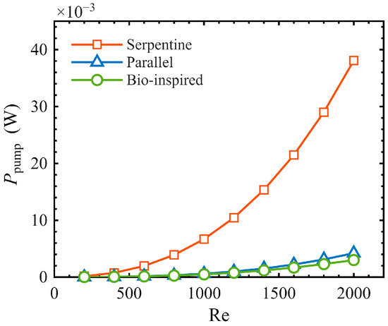
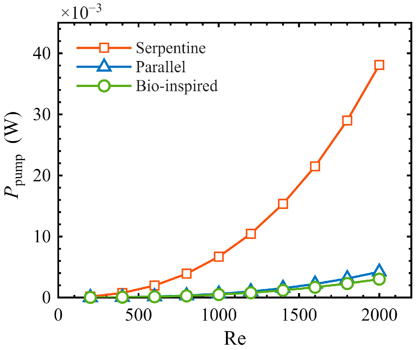
To sustain an optimal operating temperature within the PEMFC stack, the active liquid cooling system inevitably imposes a parasitic pumping power demand for continuous coolant circulation, which directly reduces the net power output of the entire system. Based on the pressure drop data extracted from the preceding hydrodynamic simulation, the evolution of the parasitic pumping power at the single-plate level was quantitatively evaluated across the inlet Re range of 200 to 2000, as depicted in Figure 9.
Figure 9.
Variation in the parasitic pumping power as a function of the inlet Re.
The results demonstrate a pronounced positive correlation between the evolution of system-level parasitic pumping power and the pressure drop curve. At a high inlet Re of 600, the multi-branch fluid splitting of the conventional parallel flow channel restricts the single-plate parasitic pumping power to 1.45 × 10⁻⁴ W. Conversely, burdened by severe frictional drag and localized form drag, the parasitic pumping power of serpentine flow channel rises significantly to 1.96 × 10⁻³ W under the identical operating conditions. Although this absolute magnitude may appear negligible at the single-cell level, the energy penalty associated with high internal flow resistance scales substantially in commercial PEMFC stacks operating at the kilowatt or megawatt level. This accumulated resistance translates into a substantial system parasitic burden, which subsequently decreases the overall energy conversion efficiency.
The hierarchical bifurcating network effectively suppresses momentum dissipation. Consequently, at a comparative inlet Re of 600, the parasitic pumping power of the bio-inspired channel is restricted to 1.27 × 10⁻⁴ W. Calculation results indicate that, while ensuring the average bipolar plate temperature is 347.81 K, the bio-inspired design successfully reduces the parasitic pumping power of the thermal management system by 93.5% and 12.5%, respectively, compared to the serpentine and parallel flow channels. This indicates that the bio-inspired cooling channel achieves efficient heat dissipation at a very low hydrodynamic cost while meeting the 353.15 K thermal constraint. Note that practical commercial PEMFC systems involve extra parasitic losses from manifolds and headers. Nevertheless, the significant drag reduction at the channel level provides a promising design direction to maximize stack net power output.
4. Conclusions
This study developed and validated a three-dimensional conjugate heat transfer numerical model, and proposed a bio-inspired cooling channel design for PEMFCs based on constructal theory and Murray’s law. Through numerical comparison with traditional parallel and serpentine channels, the overall thermal management performance and fluid flow characteristics of this novel structure across different operating flow rate ranges were systematically evaluated. The main conclusions are summarized as follows:
- Enhancement of thermal management and temperature uniformity. The bio-inspired cooling channel significantly outperforms traditional designs by ensuring uniform heat extraction. At the nominal inlet Re of 400, it stabilizes the average bipolar plate temperature at 349.63 K and reduces the index of uniform temperature to 1.49 K, improving upon parallel and serpentine channels by 52.8% and 13.5%, respectively. At a higher practical inlet Re of 600, the maximum temperature gradient is further suppressed with the index dropping to 1.07 K. This effectively mitigates localized hot spots and prolongs the service life of the proton exchange membrane.
- Optimization of hydrodynamic performance and flow distribution. Guided by constructal theory and Murray’s law, the proposed bifurcation network effectively circumvents the geometric limitations of traditional designs. Detailed flow channel analyses reveal that the bio-inspired structure facilitates smooth momentum transitions at each bifurcation node. This design mitigates the inlet-inertia-induced flow maldistribution inherent in parallel channels, and largely eliminates the severe localized form drag and momentum dissipation caused by frequent 180° U-turns in serpentine channels.
- Minimization of parasitic pumping power. The bio-inspired flow channel reduces drag and parasitic pumping power. At an inlet Re of 600, the overall pressure drop is 68.44 Pa, with a single-plate parasitic pumping power of 1.27 × 10⁻⁴ W. Under equivalent heat dissipation requirements, the bio-inspired channel reduces the parasitic power consumption by 93.5% and 12.5% compared to the serpentine and parallel channels, respectively.
In summary, the bio-inspired cooling channel mitigates the trade-off between heat transfer augmentation and increased flow resistance at the single-plate level. This configuration offers a promising design for large-scale thermal management. However, practical high-power PEMFC stacks will inevitably face additional system-level flow losses from manifolds, headers, and external coolant loops. Future studies must account for these system-level pressure drops to fully assess the energy-saving potential of this design in commercial applications.
Author Contributions
Conceptualization, J.W. and Q.X.; methodology, J.W.; software, J.W. and Q.X.; visualization, I.T. and X.M.; formal analysis I.T. and J.M.; validation, J.W., Q.X. and C.S.; investigation, J.W., X.M. and J.M.; data curation, J.W., X.M. and J.M.; Resources W.H. and C.S.; Supervision C.S., I.T. and Q.X.; Project administration, W.H. and C.S.; Funding acquisition, C.S.; writing—original draft preparation, J.W. and C.S.; writing—review and editing, Q.X., W.H. and C.S. All authors have read and agreed to the published version of the manuscript.
Funding
This research was funded by the National Natural Science Foundation of China (Grant No. 52407239). The authors acknowledge the 2023 Youth Talent Introduction Scientific Research Startup Fee (Grant No. AUGA2160100623) and 2023 Support Funds for Talent Introduction in Heilongjiang Province (Grant No. AUGA2160501723) provided by the Harbin Institute of Technology, China.
Data Availability Statement
The original contributions presented in the study are included in the article; further inquiries can be directed to the corresponding authors.
Acknowledgments
We would like to thank Shihao Zhu from the School of Electrical Engineering and Automation of Harbin Institute of Technology for providing the language polishing support and formatting correction for the manuscript.
Conflicts of Interest
The authors declare no conflicts of interest.
Abbreviations
The following abbreviations are used in this manuscript:
| PEMFCs | Proton exchange membrane fuel cells |
| Re | Reynolds number |
| sCO2 | Supercritical carbon dioxide |
| CFD | Computational fluid dynamics |
| IUT | Index of uniform temperature |
| ΔP | Pressure drop |
| amb | Ambient |
| avg | Average |
| cool | Coolant |
| gen | Generation |
| ref | Reference |
| in | Inlet |
| out | Outlet |
References
- Meng, X.; Mei, J.; Tang, X.; Jiang, J.; Sun, C.; Song, K. The degradation prediction of proton exchange membrane fuel cell performance based on a transformer model. Energies 2024, 17, 3050. [Google Scholar] [CrossRef] [Scilit]
- Zhu, K.Q.; Ding, Q.; Zhang, B.X.; Xu, J.H.; Li, D.D.; Yang, Y.R.; Lee, D.J.; Wan, Z.M.; Wang, X.D. Performance enhancement of air-cooled PEMFC stack by employing tapered oblique fin channels: Experimental study of a full stack and numerical analysis of a typical single cell. Appl. Energy 2024, 358, 122595. [Google Scholar] [CrossRef] [Scilit]
- Pei, Y.; Chen, F. Real-time water content regulation in PEMFC shutdown via MPC with SH-AUKF-based state feedback: Towards improved efficiency and reduced energy consumption. eTransportation 2025, 25, 100461. [Google Scholar] [CrossRef] [Scilit]
- Manoo, M.U.; Shaikh, F.; Kumar, L.; Arıcı, M. Comparative techno-economic analysis of various stand-alone and grid connected (solar/wind/fuel cell) renewable energy systems. Int. J. Hydrogen Energy 2024, 52, 397–414. [Google Scholar] [CrossRef] [Scilit]
- Tang, X.; Yang, M.; Shi, L.; Hou, Z.; Xu, S.; Sun, C. Adaptive state-of-health temperature sensitivity characteristics for durability improvement of PEM fuel cells. Chem. Eng. J. 2024, 491, 151951. [Google Scholar] [CrossRef] [Scilit]
- Song, Y.; Guo, Z.; Yin, J.; Liu, M.; Tolj, I.; Grigoriev, S.A.; Ge, M.; Sun, C. Investigations of the Sulfonated Poly (Ether Ether Ketone) Membranes with Various Degrees of Sulfonation by Considering Durability for the Proton Exchange Membrane Fuel Cell (PEMFC) Applications. Polymers 2025, 17, 2181. [Google Scholar] [CrossRef] [Scilit] [PubMed]
- Mei, J.; Li, Z.; Song, K.; Meng, X.; Wu, H.; Tang, X.; Hasanien, H.M.; Li, Y.; Sun, C. SOH-Disparity-Aware Energy Management for Multi-Stack Fuel Cells Using Enhanced Soft Actor-Critic Reinforcement Learning. IEEE Trans. Transp. Electrif. 2026, early access. [Google Scholar]
- Zhang, G.; Kandlikar, S.G. A critical review of cooling techniques in proton exchange membrane fuel cell stacks. Int. J. Hydrogen Energy 2012, 37, 2412–2429. [Google Scholar] [CrossRef] [Scilit]
- Yang, L.; Nik-Ghazali, N.N.; Ali, M.A.; Chong, W.T.; Yang, Z.; Liu, H. A review on thermal management in proton exchange membrane fuel cells: Temperature distribution and control. Renew. Sustain. Energy Rev. 2023, 187, 113737. [Google Scholar] [CrossRef] [Scilit]
- Wang, Q.; Li, B.; Yang, D.; Dai, H.; Zheng, J.P.; Ming, P.; Zhang, C. Research progress of heat transfer inside proton exchange membrane fuel cells. J. Power Sources 2021, 492, 229613. [Google Scholar] [CrossRef] [Scilit]
- Song, K.; Hou, T.; Jiang, J.; Grigoriev, S.A.; Fan, F.; Qin, J.; Wang, Z.; Sun, C. Thermal management of liquid-cooled proton exchange membrane fuel cell: A review. J. Power Sources 2025, 648, 237227. [Google Scholar] [CrossRef] [Scilit]
- Chen, X.; Liu, Q.; Fang, Y.; He, L.; Huang, T.; Zhang, Y.; Wan, Z.; Wang, X. Numerical study of a MIMO-shaped cooling plate in PEMFC stack for heat transfer enhancement. Energy Rep. 2021, 7, 5804–5814. [Google Scholar] [CrossRef] [Scilit]
- Rahgoshay, S.M.; Ranjbar, A.A.; Ramiar, A.; Alizadeh, E. Thermal investigation of a PEM fuel cell with cooling flow channel. Energy 2017, 134, 61–73. [Google Scholar] [CrossRef] [Scilit]
- Huang, T.; Zhang, P.; Zou, P.; Chen, H.; Chen, S.; Guo, X.; Chen, Y.; Wan, Z.; Zeng, W. Novel cooling flow channel for proton exchange membrane fuel cells based on sidewall lateral interconnection: Design and performance verification of the lateral interlinked channel. Chem. Eng. J. 2025, 526, 170920. [Google Scholar] [CrossRef] [Scilit]
- Huang, T.; Zhang, P.; Xiao, Y.; Chen, Y.; Wan, Z.; Tu, Z.; Wang, L.; Chan, S.H.; Zeng, W. Novel Design of Obstacles with Different Spacing in the Cooling Channel for Proton Exchange Membrane Fuel Cell. ACS Sustain. Chem. Eng. 2025, 13, 17257–17274. [Google Scholar] [CrossRef] [Scilit]
- Wang, N.; Li, C.; Li, W.; Chen, X.; Li, Y.; Qi, D. Heat dissipation optimization for a serpentine liquid cooling battery thermal management system: An application of surrogate assisted approach. J. Energy Storage 2021, 40, 102771. [Google Scholar] [CrossRef] [Scilit]
- González-Morán, L.; Suárez, C.; Iranzo, A.; Han, L.; Rosa, F. A numerical study on heat transfer for serpentine-type cooling channels in a PEM fuel cell stack. Energy 2024, 307, 132634. [Google Scholar] [CrossRef] [Scilit]
- Khoshvaght-Aliabadi, M.; Ghodrati, P.; Kang, Y.T. Performance analysis of supercritical carbon dioxide as a coolant in cold plate systems. Energy 2025, 314, 134301. [Google Scholar] [CrossRef] [Scilit]
- Zhang, S.; Xu, H.; Qu, Z.; Liu, S.; Talkhoncheh, F.K. Bio-inspired flow channel designs for proton exchange membrane fuel cells: A review. J. Power Sources 2022, 522, 231003. [Google Scholar] [CrossRef] [Scilit]
- Choi, J.; Park, Y.; Park, J.; Kim, C.; Heo, S.; Kim, S.D.; Ju, H. Innovative flow field design strategies for performance optimization in polymer electrolyte membrane fuel cells. Appl. Energy 2025, 377, 124551. [Google Scholar] [CrossRef] [Scilit]
- Yang, R.; Zheng, Y.; Bian, J.; Lu, J.; Yang, Y. Bio-inspired intersecting-leaves flow field for proton exchange membrane fuel cells: A Murray’s law approach to optimizing sub-channel design for improved efficiency. Appl. Therm. Eng. 2025, 280, 128249. [Google Scholar] [CrossRef] [Scilit]
- Liu, Z.; Liu, W.; Lv, S. Numerical study of battery thermal management system using bio-inspired leaf-shaped channel liquid cooling plate. Appl. Therm. Eng. 2025, 268, 125898. [Google Scholar] [CrossRef] [Scilit]
- Zhang, F.; Wang, C.; Qiu, S.; Teng, G.; Zhang, C.; Zhou, Y. Thermal performance of a novel fin-liquid cooling plate with bio-inspired leaf vein flow channels. Int. Commun. Heat. Mass. Transf. 2026, 176, 111276. [Google Scholar] [CrossRef] [Scilit]
- Fan, X.; Meng, C.; Yang, Y.; Lin, J.; Li, W.; Zhao, Y.; Xie, S.; Jiang, C. Numerical optimization of the cooling effect of a bio-inspired fishbone channel liquid cooling plate for a large prismatic lithium-ion battery pack with high discharge rate. J. Energy Storage 2023, 72, 108239. [Google Scholar] [CrossRef] [Scilit]
- Wang, J.; Liu, X.; Liu, F.; Liu, Y.; Wang, F.; Yang, N. Numerical optimization of the cooling effect of the bio-inspired spider-web channel cold plate on a pouch lithium-ion battery. Case Stud. Therm. Eng. 2021, 26, 101124. [Google Scholar] [CrossRef] [Scilit]
- Bejan, A.; Errera, M.R. Deterministic tree networks for fluid flow: Geometry for minimal flow resistance between a volume and one point. Fractals 1997, 5, 685–695. [Google Scholar] [CrossRef] [Scilit]
- Murray, C.D. The physiological principle of minimum work: I. The vascular system and the cost of blood volume. Proc. Natl. Acad. Sci. USA 1926, 12, 207–214. [Google Scholar] [CrossRef] [Scilit] [PubMed]
- Tan, Q.; Lei, H.; Liu, Z. Numerical simulation analysis of the performance on the PEMFC with a new flow field designed based on constructal-theory. Int. J. Hydrogen Energy 2022, 47, 11975–11990. [Google Scholar] [CrossRef] [Scilit]
- Wang, Y.; Sun, Z.Y.; Yang, L. Optimizing temperature distribution in a PEMFC stack: A computational study on cooling plate and coolant dynamics. Int. J. Hydrogen Energy 2025, 97, 88–103. [Google Scholar] [CrossRef] [Scilit]
- Xin, Q.; Wang, J.; Mei, J.; Li, Z.; Tolj, I.; Korpebayev, D.; Bai, X.; Sun, C. Comprehensive performance analysis and optimization of the closed Brayton cycle for waste heat recovery and cooling in hydrogen aeroengines. Energy 2026, 349, 140647. [Google Scholar] [CrossRef] [Scilit]
- Baek, S.M.; Yu, S.H.; Nam, J.H.; Kim, C.J. A numerical study on uniform cooling of large-scale PEMFCs with different coolant flow field designs. Appl. Therm. Eng. 2011, 31, 1427–1434. [Google Scholar] [CrossRef] [Scilit]
- Han, J.; Park, J.; Yu, S. Control strategy of cooling system for the optimization of parasitic power of automotive fuel cell system. Int. J. Hydrogen Energy 2015, 40, 13549–13557. [Google Scholar] [CrossRef] [Scilit]
- Xia, Q.; Zhang, T.; Gao, Y.; Ye, X.; Guan, C. Optimal design of thermostat for proton exchange membrane fuel cell cooling system. Energy Convers. Manag. 2021, 248, 114800. [Google Scholar] [CrossRef] [Scilit]
- Zeiny, A.; Al-Baghdadi, M.A.; Arear, W.F.; Ismail, M.S. Al2O3–H2O nanofluids for cooling PEM fuel cells: A critical assessment. Int. J. Hydrogen Energy 2022, 47, 38823–38836. [Google Scholar] [CrossRef] [Scilit]
- Chen, X.; Li, W.; Gong, G.; Wan, Z.; Tu, Z. Parametric analysis and optimization of PEMFC system for maximum power and efficiency using MOEA/D. Appl. Therm. Eng. 2017, 121, 400–409. [Google Scholar] [CrossRef] [Scilit]
- Chen, X.; Long, S.; He, L.; Wang, C.; Chai, F.; Kong, X.; Wan, Z.; Song, X.; Tu, Z. Performance evaluation on thermodynamics-economy-environment of PEMFC vehicle power system under dynamic condition. Energy Convers. Manag. 2022, 269, 116082. [Google Scholar] [CrossRef] [Scilit]
- Li, H.; Ding, X.; Meng, F.; Jing, D.; Xiong, M. Optimal design and thermal modelling for liquid-cooled heat sink based on multi-objective topology optimization: An experimental and numerical study. Int. J. Heat Mass Transf. 2019, 144, 118638. [Google Scholar] [CrossRef] [Scilit]

Disclaimer/Publisher’s Note: The statements, opinions and data contained in all publications are solely those of the individual author(s) and contributor(s) and not of MDPI and/or the editor(s). MDPI and/or the editor(s) disclaim responsibility for any injury to people or property resulting from any ideas, methods, instructions or products referred to in the content. |
© 2026 by the authors. Licensee MDPI, Basel, Switzerland. This article is an open access article distributed under the terms and conditions of the Creative Commons Attribution (CC BY) license.