


Abstract
The new energy vehicle (NEV) industry is expanding globally, yet safety accidents induced by collisions have become a major challenge to its high-quality development. In addition, the risks associated with battery state variations from fast-charging cycling cannot be ignored. To investigate the coupled effects of electrochemical degradation and mechanical loading on battery safety, a series of cross-factor-controlled mechanical experiments has been proposed based on 12 prismatic lithium-ion batteries across three aging states and two loading directions. The results indicate that the difference in loading orientation affects the mechanical safety responses. Under horizontal loading, interlayer slip dissipates the impact energy, and damage is concentrated in a localized area. In contrast, vertical loading is prone to inducing penetration-type damage to the structure, characterized by large-scale interlayer slip and multi-point separator damage. Moreover, once thermal runaway is triggered under vertical loading, the peak surface temperature is significantly higher. Loading orientation exerts an influence on the load-bearing capacity under mechanical damage, while electrochemical aging further reduces the safety margin of the batteries. The coupling effect of these two factors exacerbates the risk of impact failure. Consequently, if testing is based solely on fresh batteries, it tends to overestimate the safety boundary of in-service batteries. These results provide theoretical and data support for optimizing the structural design of battery systems, which is of great significance for the high-quality advancement of the NEV industry.
1. Introduction
The global industrialization of new energy vehicles (NEVs) is continuously expanding, and the safety of traction batteries, as a core vehicular component, has garnered considerable attention [1]. In particular, impacts from road debris, curb protrusions, and potholes on the underbody of battery packs pose a significant safety hazard. Relevant studies have identified bottom mechanical damage as a primary cause of fires in NEVs [2,3]. With the large-scale popularization of NEVs, fast-charging technology has become a critical approach for rapid energy replenishment of traction batteries, which also introduces new safety risks, especially in scenarios involving bottom collision of battery packs [4,5]. Charge–discharge cycling can induce multiple electrochemical and thermal safety hazards. Fast-charging with high current exacerbates electrode polarization, and the imbalance in the lithium-ion extraction rate can easily precipitate lithium dendrites on the negative electrode surface, which may pierce the separator and trigger an internal short circuit. Long term fast-charging cycles promote metallic lithium deposition on the graphite negative electrode surface [6], while causing repeated damage and regeneration of the SE film, leading to an increase in its thickness and a significant degradation in its mechanical toughness. Transition metal leaching exacerbates electrolyte catalytic side reactions, and multiple interface defects jointly reduce the battery’s anti-extrusion and anti-shear mechanical properties. In addition, the battery’s internal resistance increases markedly, and the risk of thermal runaway triggering is substantially elevated [7].
Hailing Luo et al. conducted quasi-static tests on pouch lithium-ion batteries using spherical indentation, revealing the progressive damage evolution under mechanical loading [8]. Weiwei Wang et al. addressed the safety issue of short circuits and fires caused by foreign objects impacting the bottom of traction battery packs on roads; through quasi-static compression and dynamic impact tests, a homogenized finite element model was constructed to effectively predict the macroscopic mechanical response and internal short-circuit failure under mechanical loading [1]. Hongbo Ji et al. constructed a refined numerical calculation model containing a negative electrode–separator–positive electrode stack structure using the finite element analysis method of the steel ball indentation test scheme and fully characterized the mechanical failure behavior of the positive and negative electrodes [9]. Juner Zhu et al. conducted axial quasi compression tests on 18,650 cylindrical batteries and identified four distinct deformation stages during axial compression: elastic compaction, pole-roll hardening, buckling-induced short circuit, and shell strengthening. They further found that the sharp edge of the pole piece piercing the separator is one of the core causes of internal short circuits [10]. Shoujun Xi et al. performed dynamic impact multiphysics experiments on prismatic batteries under multiple impact velocities. Based on the experimental data, they established a computational model to analyze the mechanical response of the battery; subsequently, the dynamic response under various conditions was analyzed using this model [11]. Hanfeng Yin et al. conducted hemispherical indentation tests on battery samples containing typical interlayers to investigate the deformation and progressive failure behavior of battery components, capturing the overall stress–strain response and final failure characteristics of the battery structure [12]. Marvin Sprenger et al. compared the lateral compression load response of fresh and cyclically aged NCM pouch cells at 90% SOH through multi-scale mechanical tests, and elucidated the underlying mechanism that increases the likelihood of significant voltage anomalies in aged batteries after chassis collisions, from a mechanical electrochemical coupling perspective [13]. Le Tong et al. investigated the mechanism by which high- and low-temperature cyclic aging affects overcharging-induced thermal runaway. They found that the reaction between lithium plating and the electrolyte, induced by low-temperature aging, is a key triggering factor for thermal runaway during overcharging, and that aging further amplifies overall safety risks [14].
However, current research mainly focuses on the analysis of compression damage in a single direction, lacking bidirectional loading comparison and cross-experimental analysis with multi-gradient aging. In particular, the synergistic degradation mechanism coupling loading orientation with fast-charging cycling remains largely unexplored. The distinction between horizontal and vertical loading on the vehicle underbody has not been systematically addressed, and the electrochemical interface degradation induced by long-term fast-charging cycles has been largely overlooked. Consequently, conclusions drawn from such tests may deviate from the actual safety performance of batteries in service, potentially leading to safety risks.
To address these gaps, this study establishes a bottom-compression testing platform for prismatic lithium-ion batteries. Two typical bottom-loading modes (horizontal and vertical) are designed, and cross-factor experiments are performed on cells with three distinct aging states. The mechanical response, the internal short-circuit triggering threshold, and temperature evolution characteristics are compared and analyzed under various operating conditions. Furthermore, the failure mechanism of mechanical electrochemical coupling under the combined effects of loading direction and electrochemical aging is elucidated. These results provide theoretical and data support for the optimization of vehicle underbody protection structures, the revision of relevant standards, and the forensic analysis of accident-involved batteries [15].
2. Experimental
2.1. Experimental Object
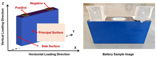
This study selected a prismatic lithium-ion battery as the experimental object. The battery has a nominal voltage of 3.7 V, a nominal capacity of 141 Ah, a working voltage range of 2.75~4.25 V, and individual dimensions of 48 mm (thickness) × 213 mm (width) × 102 mm (height). A total of 1 to 12 samples were numbered and subjected to electrochemical aging cycles and local mechanical loading tests in sequence. Establish a spatial coordinate system based on the vertical placement posture of the battery, as shown in Figure 1.
Figure 1.
Battery space coordinate system and battery sample diagram.
The X direction is the horizontal direction, corresponding to the thickness direction of the battery, and the Z direction is the vertical height direction. The positive and negative poles of the battery are arranged at the top of the Z direction, and the main surface of the battery is perpendicular to the X-axis and parallel to the Y-Z plane. The electrode plates are stacked and arranged along the thickness direction of the battery, resulting in significant anisotropy of the battery under different directional loads, providing a research carrier for comparing the failure differences under different mechanical loading conditions.
2.2. Experimental Platform
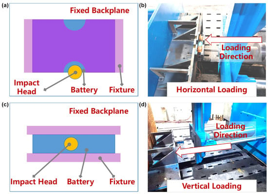
A displacement-controlled mechanical-loading local compression test was conducted using a mechanical abuse compression testing system produced by China Automotive Technology Research Center Co., Ltd., Tianjin, China. By adjusting the assembly posture of the battery on a rigid fixture, the equipment can flexibly achieve two types of damage modes: vertical and horizontal loading. It can simulate the failure scenarios of local mechanical compression of square batteries under different direction loads, providing support for conducting multi-directional and multi aging state-battery cross control tests in this study and accurately capturing the critical characteristic parameters of short-circuit failure inside the battery. The mechanical abuse compression testing system is shown in Figure 2.
Figure 2.
Schematic diagram of battery bottom loading method and experimental state picture with a hemispherical indenter diameter 30 mm: (a) horizontal loading diagram; (b) horizontal loading experimental state image; (c) vertical loading diagram; (d) vertical loading experimental state image.
The mechanical loading head adopts a rigid hemispherical head with a diameter of 30 mm, and its geometric form matches the shape of road gravel and hard objects on the road surface, which can truly reproduce the local concentrated point load caused by the collision at the bottom of the actual vehicle. The upper and lower end faces of the battery are fully constrained and clamped using rigid fixtures, replicating the internal assembly boundary conditions of the prismatic lithium-ion cell, effectively eliminating test errors caused by free boundary deformation, and ensuring the consistency of load transmission. During the experiment, the testing platform should be equipped with a water tank and adequate ventilation. In case of an emergency, appropriate measures should be taken using the available firefighting equipment.
The scenario of bottom collision can be divided into two types from the perspective of load application: during the vehicle’s driving process, the bottom of the battery system scratches hard foreign objects on the road surface. One type of load application is the horizontal compression damage to the bottom of the battery, defined as X-direction horizontal mechanical loading. The other type of load application is the vertical mechanical loading of road surface protrusions and hard objects on the bottom of the battery, defined as Z-direction bottom mechanical loading. There are anisotropic differences in the stress transmission path and pole piece damage mode between the two types of loads. According to the battery spatial coordinate system, the two types of loading conditions strictly correspond to the actual vehicle accident scenario in terms of load position and direction: in the horizontal loading mode, the X-direction load acts vertically on the center of the thick surface of the battery, corresponding to the bottom horizontal mechanical loading condition formed by scraping hard foreign objects during vehicle driving; in the vertical loading mode, the Z-direction load is applied to the center of the bottom end face of the battery, simulating the vertical mechanical loading condition caused by the impact of a hard object on the bottom of the battery pack. The mechanical loading rate of 10 mm/s is uniformly set for controlled comparison rather than true impact replication, which is suitable for studying quasi-static extrusion damage mechanism of the battery bottom according to practical engineering experience.
During the experiment, the system synchronously collects force displacement data, voltage, and temperature data to achieve synchronous recording of mechanical, electrochemical, and thermal multiphysics field signals. As shown in Figure 1, 4K-type thermocouples were arranged at the center points of the positive electrode, negative electrode, principle surface, and side surface, fixed with high-temperature adhesive tape, the sampling frequency is set at 100 Hz and the measuring range is 0–1000 °C. The battery has a thickness of 48 mm in the through-thickness direction. Considering possible scratching and mechanical damage to the bottom of the battery during the test, we set the termination conditions as follows: The termination criterion for the experiment is uniformly defined as the appearance of visible smoke on the battery surface (indicating thermal runaway) or the attainment of a predetermined extrusion displacement of 50 mm. Once either condition is satisfied, the loading is stopped immediately, and the cell is left to rest under observation for 2 h.
2.3. Scheme Design
This study designs control variable experiments from two dimensions: loading direction and aging state. The mechanical damage failure law under multifactor coupling is systematically studied. Two parallel samples are used for each working condition to conduct mechanical damage loading tests. The specific variable settings are as follows: load direction, and set X and Z directions. The X-direction loading refers to the local impact along the thickness direction at the bottom, corresponding to the positive scraping of the bottom at the system level. Z-direction loading refers to the local impact at the bottom along the height direction, corresponding to the system level vertical impact transmitted to the load mode of the individual unit. The aging state includes three states: fresh state, 1C normal cycle aging, and 3C fast-charging cycle aging. The aged samples were subjected to cyclic aging at a constant temperature of 25 °C for 800 times, corresponding to the full life cycle mechanical safety degradation characteristics under different user scenarios. All cells were charged to 50% SOC before mechanical tests. For aged cells, the charging capacity was calculated based on their measured actual capacity to ensure consistent actual SOC across all groups. After charging, all cells rested for 7 days at 25 °C ambient temperature to ensure voltage and temperature stabilization before mechanical loading.
The 12 prismatic cells are numbered 1 to 12 and divided into two loading groups, as detailed in Table 1. Samples 1–6 undergo horizontal local compression on the bottom of the large face, while Samples 7–12 undergo vertical local compression on the bottom edge. Each loading group includes three cell states: 3C fast-charged aged (2 cells), 1C normal-cycled aged (2 cells) and fresh (2 cells).
Table 1.
Summary of experimental cell numbers.
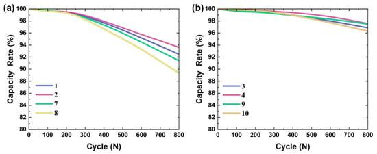
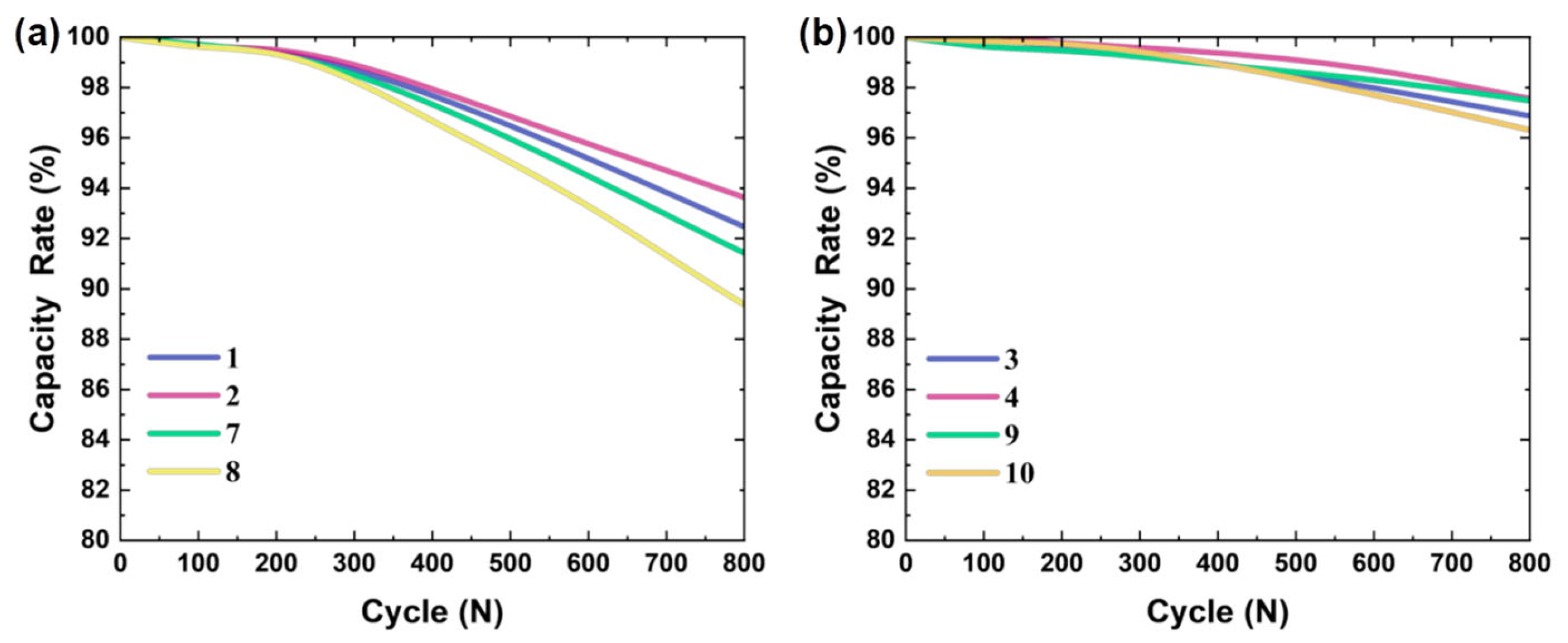
The aging cycle is carried out using a battery charge and a discharge cycle testing system, with a constant test environment of 25 °C. For fresh and 1C aged batteries, a constant current of 1C is charged to the cut-off voltage 4.2 V. For 3C aged batteries, a constant current of 3C is charged to the cut-off voltage. A total of 8 batteries undergo an 800 charge and discharge cycles of aging. The evolution of battery capacity retention rate under two aging mechanisms is shown in Figure 3a shows the capacity decay curves of 1, 2, 7, and 8 fast-charging cycling batteries, corresponding to the 3C fast-charging cycle scheme; Figure 3b shows the capacity decay curves of 3, 4, 9, and 10 normally aged batteries, corresponding to the 1C normal charge–discharge cycle system. From the capacity decay curve, it can be seen that in the early stage of cycling from 0 to 200 times, the decrease in capacity retention rate of all batteries is gentle, and only weak reversible interface-side reactions occur inside the battery. When the number of cycles exceeds 200 times, the capacity decay rate gradually accelerates, and the decay amplitude of fast-charging cycling batteries is significantly higher than that of conventional cycling batteries. After 800 cycles, the capacity retention of the batteries in the fast-charging cycling group was approximately 90%, while that of the conventional cycling aging group was generally higher. However, since the samples were selected from the same batch, this result may have overlooked the potential individual differences among the tested cells.
Figure 3.
The relationship between the capacity retention rate and the number of cycles for fast-charging cycle aging and normal cycle aging of batteries: (a) fast-charging cycling battery capacity decay curve; (b) normal aging battery capacity decay curve.
3. Results and Discussion
3.1. Bottom Horizontal Load Damage Response Characteristics
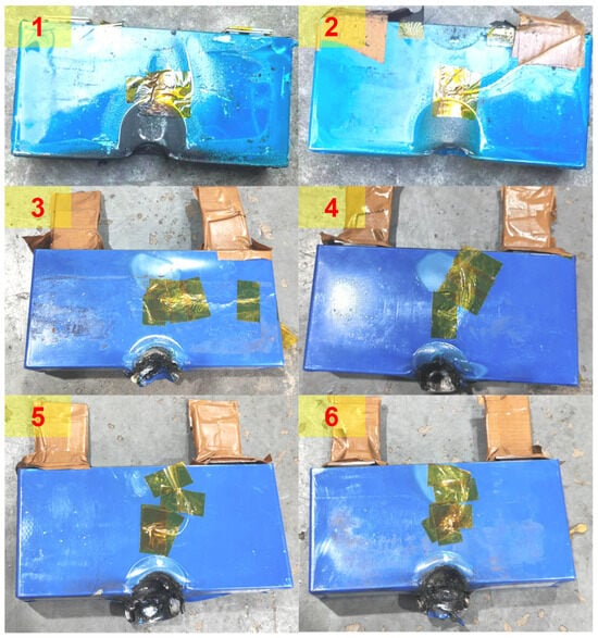
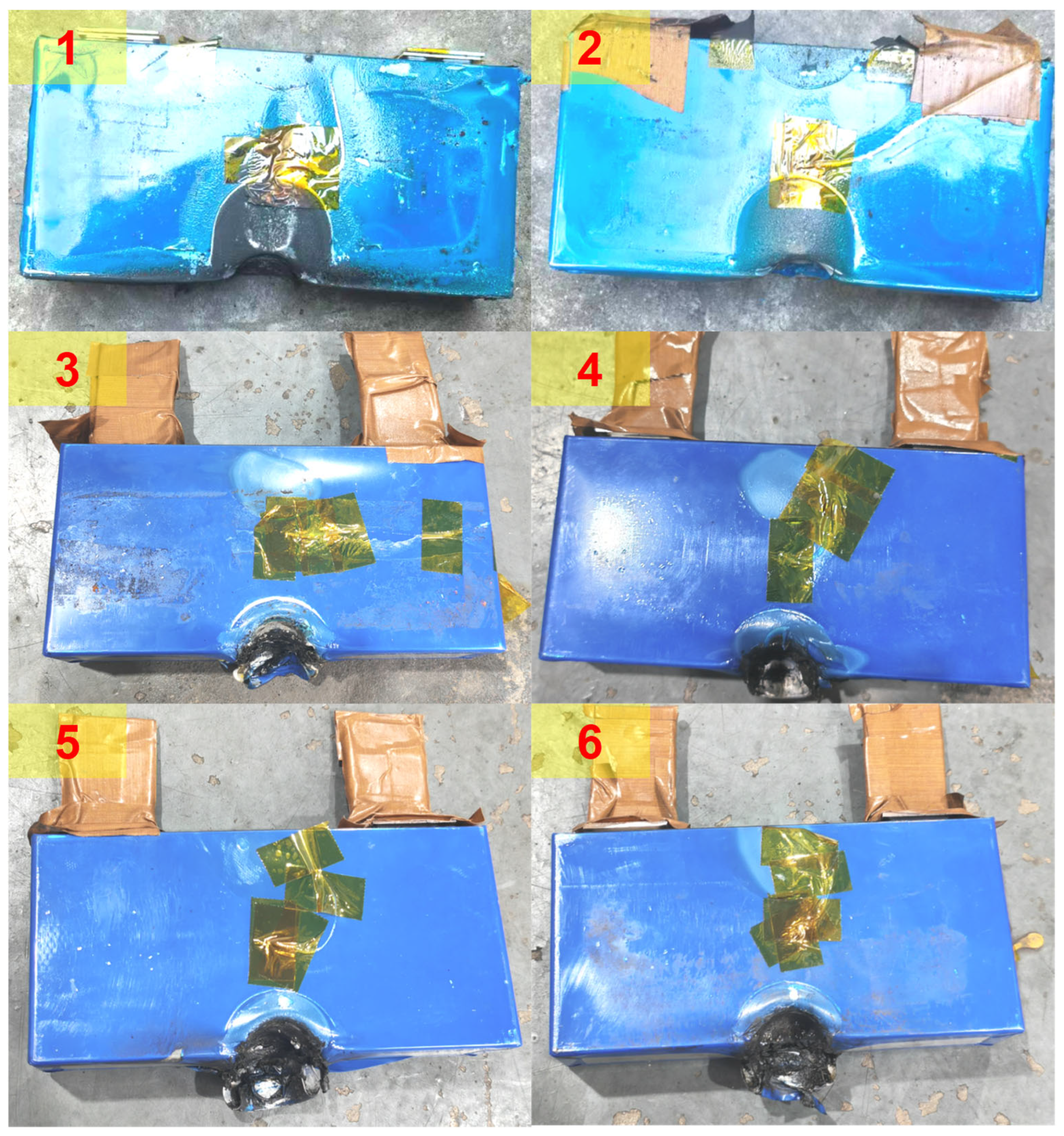
Based on the bottom horizontal and vertical mechanical loading conditions, the multiphysics field response results of force signals, electrical signals, and thermal signals from six cross experiments of fresh batteries, fast-charging aged batteries, and normal aging were analyzed to investigate the safety performance effects of loading orientation and battery state on mechanical threshold, electrical signal mutation, and temperature rise evolution. As shown in Figure 4, the appearance damage morphology of batteries 1–6 after the X-direction horizontal local compression test is presented. All batteries formed obvious local depressions in the contact area of the hemispherical indenter, and the aluminum shell underwent plastic deformation and damage. The internal electrolyte leaked out and produced black burning products. The damage was concentrated in the contact area of the indenter and did not extend widely along the shell. During the horizontal-load loading process at the bottom, obvious smoking phenomena were observed in the batteries, and the experiment was stopped. According to the appearance of the damage morphology, it can be clearly seen that electrochemical reactions occurred at the bottom of the battery.
Figure 4.
Damage results of horizontal loading at the bottom of the batteries. Numbers 1–6 indicate the battery numbers.
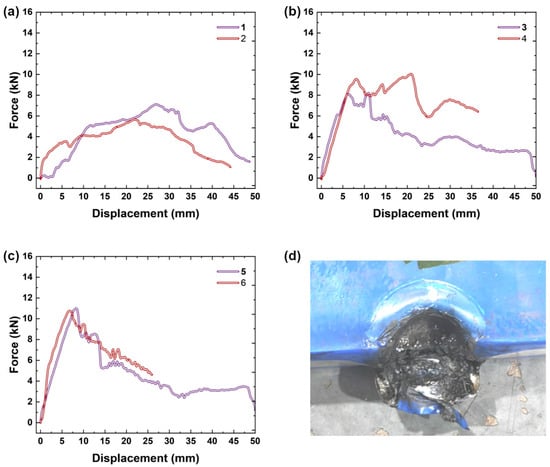
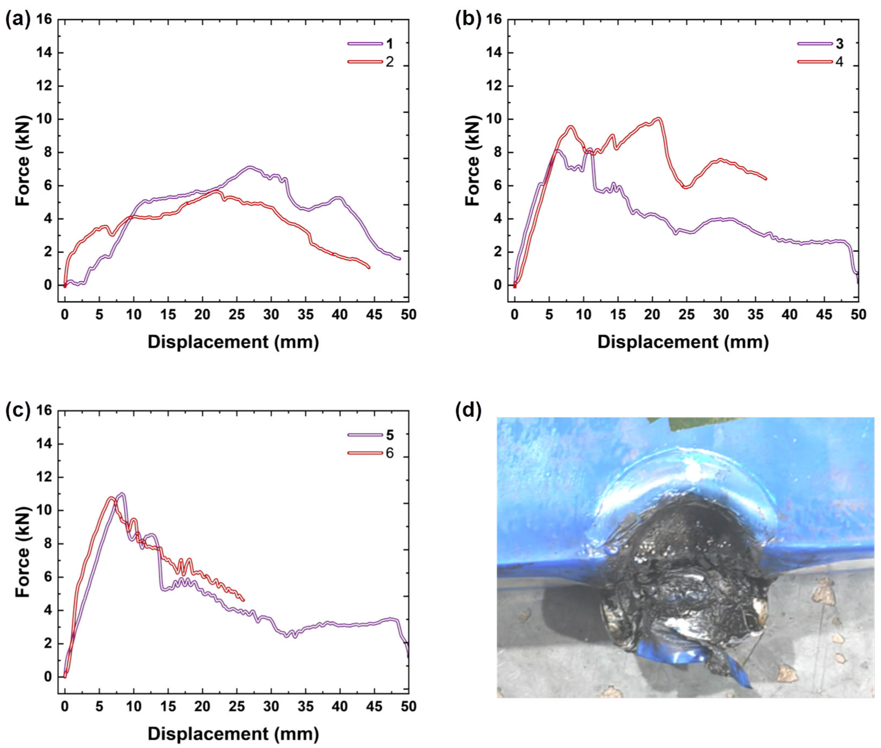
The displacement response characteristics of the bottom horizontal loading are shown in Figure 5, and the load response trends of each working condition are basically the same, which can reflect the mechanical bearing behavior of the battery from initial deformation to structural failure. In the initial stage of loading, as the displacement of the impact head continues to increase, the maximum load of Battery 6 continues to rise to a peak of 11.2 kN. The aluminum shell is depressed, and the internal pole pieces and separators gradually bear the squeezing effect, causing the bottom shell of the battery to rupture. Subsequently, the load began to gradually decrease, accompanied by sustained fluctuations. The load fluctuations after the peak may be caused by the continuous local sliding of the internal structure of the battery and the continuous reconstruction of the contact state.
Figure 5.
The differences in displacement response characteristics of horizontal loading load at the bottom and the schematic diagram of bottom damage results: (a) response of batteries 1 and 2; (b) response of batteries 3 and 4; (c) response of batteries 5 and 6; (d) damage result at the bottom of battery 6.
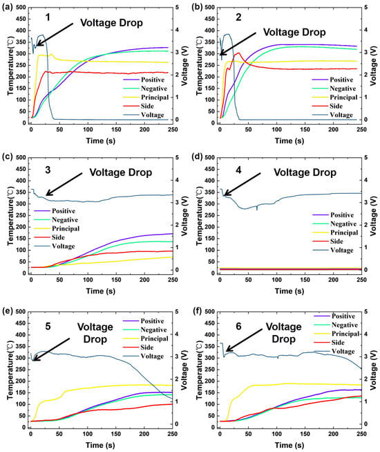
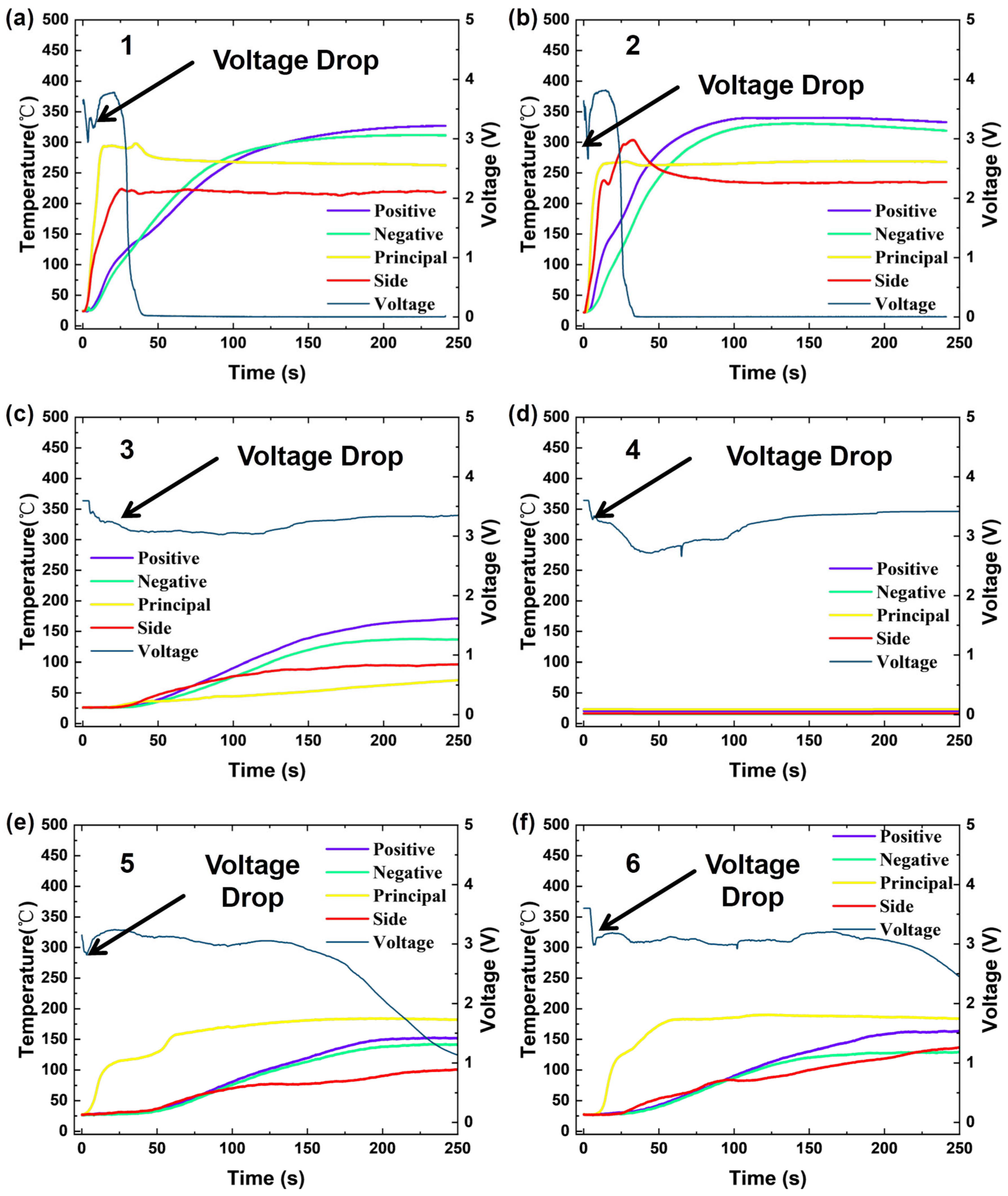
The voltage and temperature signal response results of the battery during the bottom horizontal-load loading process are shown in Figure 6. By monitoring the temperature change trends of the positive, negative, main plane, and side of the battery, it can be seen that except for the fourth battery, there was a significant temperature rise at the monitored points during the bottom horizontal loading process, which is consistent with the observation of obvious local burning of the battery during the experiment. The temperature acquisition system of the fourth battery failed to collect the temperature rise changes at this stage due to a fault during the experiment. The batteries monitored during the experiment showed a significant downward trend, and the signal evolution of all samples exhibited phased characteristics. At the initial stage of applying compressive load, the open circuit voltage of the battery remains stable, and the temperature of each measuring point is basically maintained at the initial level of the environment. At this time, no through damage channel has been formed inside the battery, and there is no significant internal short circuit phenomenon. As the displacement of the squeezing head continues to increase, the internal structural damage of the battery accumulates continuously, and the voltage curve drops rapidly, indicating the formation of a short-circuit channel inside the battery. After the voltage drop occurs, the internal short-circuit Joule heating and interface-side reaction heat release drive the temperature of each measuring point to continue to rise. After the voltage drop, the temperature continues to rise and gradually stabilizes, reaching the temperature plateau stage. The heat generation rate and heat dissipation rate gradually reach a dynamic equilibrium. The temperature of the battery maintains a slow upward trend during long-term standing, indicating that there is a continuous interface heat-release side reaction inside the battery.
Figure 6.
The voltage and temperature signal response results during the horizontal loading process: (a) voltage and temperature signal response results of battery 1; (b) voltage and temperature signal response results of battery 2; (c) voltage and temperature signal response results of battery 3; (d) voltage and temperature signal response results of battery 4; (e) voltage and temperature signal response results of battery 5; (f) voltage and temperature signal response results of battery 6.
From the perspective of voltage evolution characteristics, once an internal short circuit is triggered, the voltage will rapidly drop in a very short period of time, and the formation of the short-circuit channel is instantaneous. The timing nodes of the voltage drop have a good correspondence with the peak load interval in the mechanical curve, and the failure of the mechanical structure is the direct cause of inducing internal short circuits. After the battery is damaged by horizontal local compression, there is a significant spatial non-uniformity in the thermal field distribution, and the damaged contact area becomes the main heat source.
3.2. Bottom Vertical Load Damage Response Characteristics
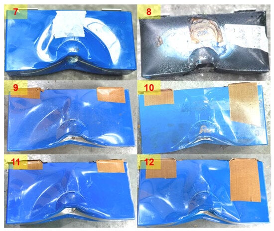
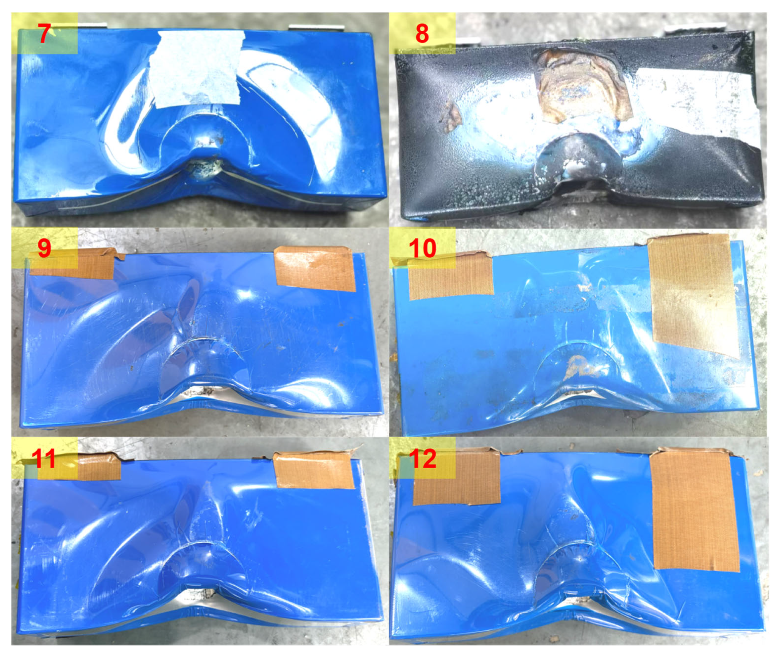
The displacement response and bottom damage results of the vertical load at the bottom are shown in Figure 7. Overall, under the concentrated load of the extrusion head, all the loaded areas at the bottom of the battery form concave deformations that match the contour of the impact head. The shell around the concave produces obvious plastic wrinkles, and the plastic deformation extends from the contact area to both sides of the battery bottom surface. The shell of the contact area of the eighth battery was damaged due to compression, and there were extensive carbonization and burning marks on the surface. The overall damage is concentrated at the center of the bottom of the battery, and the deformation shows a gradual attenuation from the impact point to both sides. The deformation area of the shell is symmetrically distributed. The plastic deformation caused by vertical load extends laterally along the bottom surface of the battery, exhibiting a wider range of shell buckling characteristics in the shell deformation mode [16].
Figure 7.
Damage results of vertical loading at the bottom of the batteries. Numbers 7–12 indicate the battery numbers.
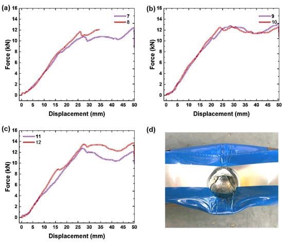
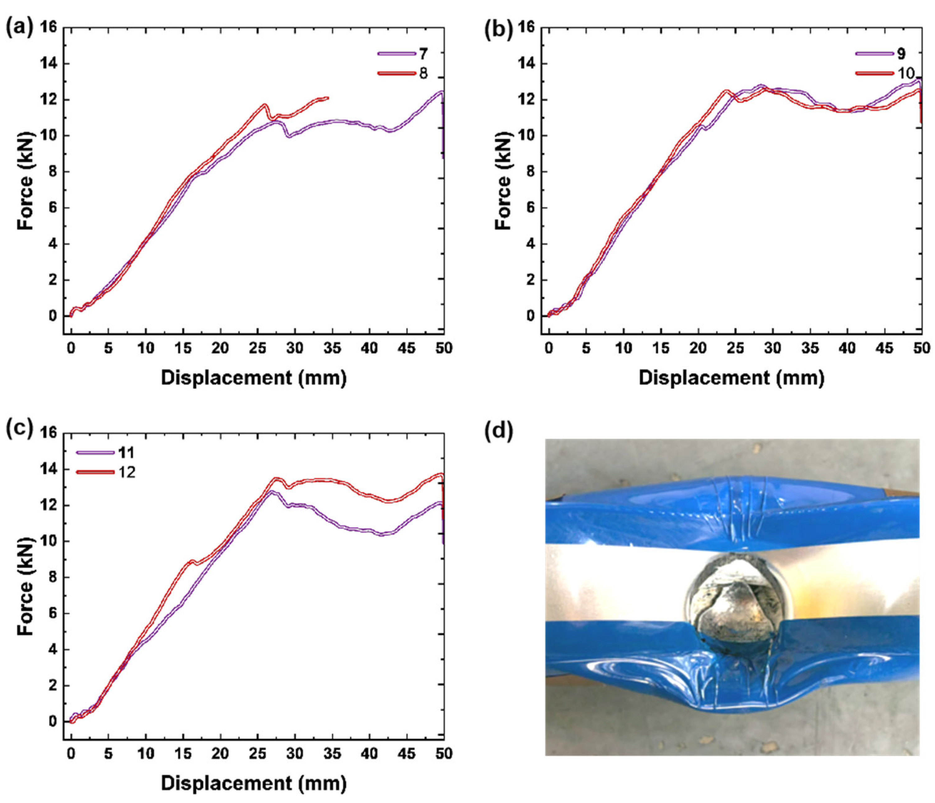
The displacement response characteristics of vertical loading at the bottom are shown in Figure 8. In the initial stage of loading, the load shows an approximately linear growth law with displacement. The battery shell and internal structure undergo elastic deformation. As the pressure head displacement continues to advance, the slope of the load gradually decreases. The battery enters the plastic deformation stage, and the load growth rate slows down and continues to rise to the peak range. After the load reaches the peak value, the overall trend shows a fluctuating and falling change, which is caused by the constantly changing contact state of the battery shell structure. During the loading process, the eighth battery experienced thermal runaway, triggering the termination condition of the experiment to stop loading. The parallel sample load response trends for each operating condition were basically the same, and after observing for 2 h, the samples that did not fail did not show any failure phenomenon, in order to ensure consistency in the analysis of failed and non-failed samples, and to focus on analyzing the safety response characteristics during mechanical loading, this study analyzed the experimental data during the mechanical loading process.
Figure 8.
The displacement response characteristics of vertical loading load at the bottom and the schematic diagram of bottom damage results: (a) response of batteries 7 and 8; (b) response of batteries 9 and 10; (c) response of batteries 11 and 12; (d) damage result at the bottom of battery 12.
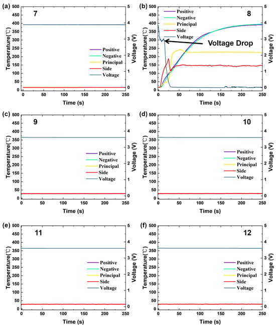
The voltage and temperature responses of the battery over time under bottom vertical mechanical loading are shown in Figure 9. By monitoring the temperature changes in the positive, negative, main plane, and side of the battery, it can be seen that except for the significant voltage drop and temperature rise caused by thermal runaway of battery No. 8, the characteristics of the test curve results for each group are basically the same. Throughout the entire loading and subsequent observation period, the voltage remained relatively stable, and the temperature at each measuring point remained at the initial ambient temperature level without any significant temperature rise. This phenomenon indicates that under the current squeezing displacement conditions, the internal separator of the battery did not form a through damaged channel and did not trigger sustained internal short circuit heat-generation behavior. However, under the load, the voltage of battery No. 8 rapidly dropped, and the temperature of each measuring point sharply increased, indicating the formation of a through short circuit inside the battery. There is a certain individual difference in whether a through short-circuit channel is formed inside the battery under the vertical load at the bottom. The temporal response results of voltage and temperature provide data support for evaluating the thermal safety risks of batteries under vertical impact loads at the bottom of vehicles.
Figure 9.
The voltage and temperature signal response results during the vertical loading process: (a) voltage and temperature signal response results of battery 7; (b) voltage and temperature signal response results of battery 8; (c) voltage and temperature signal response results of battery 9; (d) voltage and temperature signal response results of battery 10; (e) voltage and temperature signal response results of battery 11; (f) voltage and temperature signal response results of battery 12.
3.3. Differences in Damage Evolution Caused by Different Loading Directions
Comparing the voltage and temperature response curves of the square shell ternary cell under horizontal loading at the bottom of Figure 6 and vertical loading at the bottom of Figure 9, it can be seen that there are certain differences in the probability of failure, voltage drop evolution mode, and temperature rise dynamic characteristics between the two loading orientations, which intuitively reflects the differences in the failure path and internal short circuit evolution of the separator under different loading directions [17,18].
The damage evolution characteristics of two types of working conditions, bottom horizontal loading and bottom vertical loading, show certain differences in the damage results. Based on the mechanical response characteristics shown in Figure 5, for the bottom horizontal loading condition, the critical failure displacement distribution range of the battery is 7.1~27.5 mm, and the peak load range is 5.1~11.2 kN. The load displacement curve shows a gentle fluctuation and downward trend after the peak. The horizontal mechanical load at the bottom is perpendicular to the stacking direction of the pole pieces, and the layered stacking structure of the pole pieces determines the internal stress transmission path. The multi-layer pole pieces and the separator jointly share the compression load, and the interlayer slip can provide energy buffering. The damage is manifested as large-scale interlayer slip and multi-point separator puncture. When the bottom is vertically loaded, the peak load range is 10.2~13.3 kN, and the load displacement curve shows a gentle fluctuation state after the peak. Due to the fact that the load is parallel to the plane of the pole piece and concentrated on the extremely small area of the bottom end face, lacking the interlayer slip buffering mechanism, it is easy to induce local pole piece bending. However, during the structural failure process, the bending of the pole piece separator does not necessarily cause an internal short circuit because the loading direction is parallel to the separator and pole piece. Therefore, although the structure fails, the displacement of the internal short circuit is greater than that of the bottom horizontal loading process, the experimental results also show this characteristic. Under bottom vertical loading, thermal runaway was observed in one out of six cells, accounting for 16.7%. In contrast, during horizontal loading, all six cells experienced thermal runaway, accounting for 100%. The safety responses of all tested batteries are presented in Table 2.
Table 2.
Summary of the results of all 12 batteries.
At the voltage response level, the internal short-circuit failure of the bottom horizontal loading condition exhibits a continuous gradient distribution characteristic: the terminal voltage of batteries 1 and 2 undergoes an instantaneous step-like drop in the initial loading stage, rapidly dropping from the rated working voltage to nearly 0 V, corresponding to the formation of a large area of through internal short circuit inside the prismatic lithium-ion cell. The voltage of batteries 3 to 6 does not have an instantaneous sudden change and shows a gradual slow downward trend, corresponding to the continuous development process of micro short circuits caused by local separator damage. The progressive voltage drop under horizontal loading is mainly driven by the gradual expansion of internal micro short circuits. As the extrusion displacement increases, separator micro-cracks continuously propagate and new local puncture points emerge, leading to a steady increase in the effective conductive area between electrodes and a stepwise voltage decline. In addition, other potential factors could also lead to the gradual voltage drop, such as interlayer slip between electrodes, which may change the interface pressure and causes dynamic variation in internal resistance, and the gradual exfoliation of active materials from collectors under compression, which could also reduce the effective reaction area of electrodes. Under the vertical loading condition at the bottom, the failure of batteries numbered 7–12 exhibits a certain threshold effect and discreteness. Only the battery numbered eight shows a typical short-circuit characteristic of instantaneous voltage drop, while the terminal voltage of the remaining five samples remains stable throughout the entire process, without any voltage attenuation caused by micro short circuits, and there is no progressive damage state under horizontal loading.
At the temperature response level, the temperature rise patterns of the two types of loading are highly coupled with the voltage characteristics. In the horizontally loaded failure samples, the temperature of the positive and negative electrodes, main section, and side measuring points of batteries 1 and 2 rapidly rose to the range of 250~350 °C within tens of seconds, triggering severe thermal runaway. The temperature of each measuring point of batteries 3–6 showed a slow upward trend and eventually stabilized in the range of 100~150 °C, corresponding to local micro short circuit heat generation with low thermal power. Under vertical loading, the temperature rise rate of the positive and negative electrodes of battery No. 8 is faster, with a peak temperature of over 400 °C. The severity of thermal runaway is significantly higher than that under horizontal loading. The temperature at each measuring point of the remaining non-failed samples is basically the same as the initial state, without obvious Joule heating and electrochemical heat generation characteristics. The temperature rise in the No. 8 battery experiencing thermal runaway under vertical loading conditions reached a peak of 350~400 degrees Celsius, while the temperature rise in the No. 1 and No. 2 batteries in the same state reached a peak of 300~350 degrees Celsius under horizontal loading conditions. Compared to horizontal loading conditions, although the proportion of batteries experiencing thermal runaway under vertical loading conditions is lower, the peak surface temperature is significantly higher during thermal runaway, but surface peak temperature is used to characterize the severity of thermal runaway and is not directly equal to the internal heat release rate. This is because the bottom vertical loading condition causes through type damage to the middle of the battery structure, while the structural damage caused by horizontal loading is concentrated in a small area at the bottom, and the area of structural damage is smaller than that under the bottom vertical loading condition.
The above differences stem from the fundamental differences in the failure modes of the separator under the two loading modes. The horizontal lateral compression load is transmitted along the plane of the polarizer, which can easily cause overall sliding between the electrode layers, large-scale tensile tearing of the separator, and simultaneous contact of multiple electrode layers. Therefore, the internal short-circuit conduction area is large, the probability of failure is high, and it shows a continuous evolution feature from the micro short circuit to the through short circuit with the increase in load energy [19,20]. The vertical loading at the bottom is a local centralized load, and the separator is mainly in the mode of point puncture failure. Only when the intrusion depth exceeds the critical fracture strain of the separator will a short circuit be triggered. Therefore, there is a clear failure energy threshold. When the threshold is not reached, there is no obvious electrochemical damage. Once it is broken, a concentrated and severe short circuit is formed, with higher short-circuit current density, greater heat generation power, and more rapid development of thermal runaway [21]. In the study, the internal damage modes such as interlayer slip and separator puncture lack direct imaging evidence, and X-ray CT scanning and controlled disassembly of representative cells are planned in follow-up work. The bottom shell of prismatic lithium-ion cell has a stronger structural load-bearing capacity for vertical loads, and more mechanical energy is dissipated by the plastic deformation of the shell. The proportion of energy transmitted to the internal pole coil is lower, which is also an important structural mechanics reason for the lower proportion of failure samples under vertical loading [22].
3.4. Mechanism Analysis of Electromechanical Degradation Coupling Conditions
Under the bottom horizontal load loading condition, the force displacement curve of the fast-charging cycling battery in Figure 5 shows that the load increases steadily with displacement, and the load gradually decreases after reaching the peak. The peak load range of the fast-charging cycling battery is 5.1~7.2 kN, the peak load range of the normal aging battery is 8.5~10.3 kN, and the peak load range of the fresh battery is 10.9~11.2 kN. After aging, the peak load response of the battery under mechanical damage is significantly reduced. Based on the maximum mechanical response of the fast-charging cycling battery, which is 7.2 kN, it is 64.3% of the maximum mechanical response of the fresh battery, which is 11.2 kN. It can be seen that the load response ability of the aging battery is significantly reduced under the coupling condition of mechanical damage after aging. Under the vertical load condition at the bottom, the force displacement curve of the fast-charging cycling battery in Figure 8 shows that the peak load range of the fast-charging cycling battery is 10.9~11.7 kN, the peak load range of the normal aging battery is 12.4~12.5 kN, and the peak load range of the fresh battery is 12.8~13.3 kN. After aging, the peak load response of the battery under mechanical damage is significantly reduced. The maximum mechanical response based on fast-charging cycling batteries is 11.7 kN, which is 87.9% of the maximum mechanical response of fresh batteries, which is 13.3 kN. This result maintains good consistency with the bottom horizontal load loading condition, and during the bottom vertical loading process, the load-bearing capacity of aging batteries decreased by 23.6% compared to that of the bottom horizontal loading process.
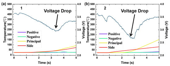
In terms of the response characteristics of electric thermal signals, the results of the bottom horizontal load loading condition show that after triggering a short circuit, the voltage of aged batteries 1 and 2 first fluctuates and drops, then rebounds, and then sharply drops again. At the moment of the first fluctuation and decrease in voltage, a rapid temperature rise and thermal runaway phenomenon occurred. After the temperature rise on the large and side surfaces reached the peak range of 200–300 degrees Celsius, the voltage completely decreased to 0. This is because local compression caused a local internal short circuit, leading to a temperature rise. The rapid increase in temperature caused a chain reaction. The voltage of normally aged batteries 3 and 4 shows a slow decline and continuous fluctuation. Within the observation time of 250 s, the voltage drops to 3.3 V and 3.4 V. The voltage of fresh batteries 5 and 6 also shows a slow decline. Within the observation time of 250 s, the voltage drops to 1.1 V and 2.4 V, and the highest temperature rise in both normally aged and fresh batteries is around 150 degrees Celsius, significantly lower than that of fast-charging aged batteries, showing a trend of gradually flattening the temperature rise in fast-charging aged batteries, normally aged batteries, and fresh batteries. Further amplifying and displaying the voltage and temperature signals of fast-charging cycling batteries under horizontal load, as shown in Figure 10, both batteries showed a decreasing trend in voltage during the 0~1 s load period, but the temperature did not change significantly during this time. Among them, the voltage of battery 1 dropped to the lowest value during this period within 2~3.5 s, and the temperature signal also showed a significant upward signal during this time range. The voltage of battery 2 dropped to the lowest value during the current period within 2~3 s, and, like battery 1, the temperature signal also showed a significant upward trend, which further indicates that the voltage and temperature signals of the battery exhibit a certain chronological order pattern when subjected to load compression [23,24].
Figure 10.
Localized enlarged view of voltage and temperature signal response during horizontal loading process: (a) response results of voltage and temperature signals for battery 1; (b) response results of voltage and temperature signals for battery 2.
Based on the above observations, the results suggest that there may be a bidirectional synergistic degradation effect between fast-charging aging and mechanical loading. Fast-charging cycling pre-induces multiple micro-defects inside the cell, including lithium deposition on the negative electrode, embrittlement of the SEI film, and fatigue micro-cracks in the separator, thereby forming a structurally degraded substrate. Subsequent external mechanical loading further promotes the continuous propagation of these defects, reducing the critical deformation threshold for inducing internal short circuits in the cell [25]. The influence of loading direction on mechanical damage cannot be ignored for prismatic aged batteries under mechanical abuse. Under horizontal loading, the multi-layer electrode stacking enables electrode layers to slip and dissipate deformation energy, so that severe structural damage and internal short circuits occur at larger compression displacements. By contrast, vertical loading produces penetrating structural destruction in the core region of the cell, leading to a higher risk of early separator puncture. The lithium metal sheet generated on the surface of graphite negative electrodes under fast-charging conditions exhibit fragile mechanical properties and are easily dislodged under compressive disturbance [26,27]. The proportion of brittle inorganic components in the SEI film regenerated by repeated damage increases, the mechanical strength of the separator decreases, and multiple interface defects jointly deteriorate the mechanical loading resistance of the battery [28]. Compared with conventional cyclic aging, the electrochemical degradation induced by fast-charging is more significant. Conducting mechanical abuse tests using only fresh cells tends to overestimate the safety margin of aged batteries in actual vehicle service and fails to reflect the real thermal runaway risk following long-term fast-charging and under-vehicle collisions [29]. Under fast-charging conditions, the concentration gradient of Li+ on the surface of graphite particles in the anode increases markedly. When the anode potential drops below 0 V, Li+ is reduced and deposited on the anode surface by combining with electrons. The deposited lithium exhibits a loose and porous structure with low mechanical strength. Under subsequent mechanical loading, the lithium deposits tend to detach, and their sharp edges impose concentrated local stress on the separator [4]. When the local stress on the separator exceeds its puncture strength limit, an internal short circuit is triggered. Furthermore, Guo et al. conducted a quantitative analysis of the degradation mechanisms in lithium-ion batteries during cycling overcharge; the contribution ratio of each damage mechanism can be calculated using the following equation [30]:
where denotes the ohmic resistance, is the resistance of the solid–electrolyte interphase (SEI) layer, represents the charge-transfer resistance, and corresponds to the Warburg diffusion resistance, LoC, LLI and LAM refer to loss of conductivity, loss of lithium inventory and loss of active material, respectively, denotes the aged battery state with a state-of-health value of , while represents the fresh cell condition.
Electrochemical aging further deteriorates the mechanical safety performance of prismatic lithium-ion cells, and notable differences exist between normal cyclic aging and fast-charging aging. Fast-charging aging accelerates active material pulverization, lithium plating, and separator pore clogging inside the cell. These aging-induced material degradations weaken the structural stability of electrode–separator stacks. When subjected to external mechanical loading, fast-charging-aged cells exhibit lower failure onset displacement and higher susceptibility to micro short circuits, compared with fresh and normally cycled counterparts [31,32]. The results of this study indicate that there may be a synergistic degradation phenomenon between fast-charging aging and mechanical loading. Aging degrades intrinsic material properties, making the cell more vulnerable to deformation. Concurrently, mechanical damage accelerates electrochemical deterioration, and this mutual reinforcement amplifies the overall safety risk of aged prismatic lithium-ion cells under crash-related mechanical abuse conditions. Owing to the limited sample size, ex situ characterization (e.g., CT scanning, SEM) will be conducted in our future work to verify the internal failure mechanisms.
4. Conclusions
In this study, prismatic lithium-ion batteries are employed to investigate mechanical failure behavior under varying loading directions and aging conditions. The multi-physical responses of fresh, conventionally cycled aged, and fast-charge aged cells are compared to elucidate the evolution of mechanical damage under coupled loading direction and electrochemical aging effects.
Loading direction significantly affects mechanical safety performance. Under horizontal impact, structural damage is concentrated in a localized bottom region, which is more confined than under vertical loading. Vertical loading induces through-thickness damage in the central region of the cell, accompanied by large-scale interlayer slip and multi-point separator damage. Although the probability of thermal runaway is lower under vertical loading, the resulting peak surface temperature is higher once it occurs. These findings provide guidance for structural design; the protective capability against horizontal mechanical compression at the bottom should be prioritized.
Owing to the limited sample size, the results suggest a potential synergistic degradation effect between fast-charging aging and mechanical loading. After aging, the peak load response of the cells under mechanical damage decreases progressively from fresh to normal aged to fast-charging aged cells under both horizontal and vertical loading. Concurrently, the peak temperature rise in aged cells is higher than that in fresh cells, following the same increasing trend across the three cell states. This is likely attributable to micro-defects induced by fast-charging cycles, such as lithium deposition on the anode and micro-damage to the separator, which weaken the mechanical load-bearing capacity of the cell structure. The observed differences in mechanical performance may arise primarily from variations in the state of health (SOH) rather than from distinct aging mechanisms themselves; the independent contribution of aging mechanisms requires further verification through matched-SOH tests in future work.
Future research will focus on constructing a multiphysics-coupled numerical model that accounts for aging effects, quantifying the influences of loading direction and aging degree on safety performance, and establishing a safety warning methodology for traction batteries under crash scenarios.
Author Contributions
Conceptualization, P.Y. and F.W.; methodology, P.Y., G.H. and Z.S.; formal analysis, P.Y.; investigation, P.Y.; resources, L.L.; data curation, P.Y.; writing—original draft preparation, P.Y.; writing—review and editing, P.Y.; visualization, Z.S.; supervision, T.M., F.W., L.L. and G.H. All authors have read and agreed to the published version of the manuscript.
Funding
This research was funded by the National Natural Science Foundation of China, grant number 52575169, China Automotive Technology Research Center Youth Science and technology talent training project, grant number 25276309, the National Key R&D Program of China, grant number 2024YFB2505004. The APC was funded by China Automotive Technology Research Center Youth Science and technology talent training project, grant number 25276309.
Data Availability Statement
The data presented in this study are available on request from the corresponding author due to the restrictions of industrial data confidentiality.
Conflicts of Interest
Authors Pengfei Yan, Tianyi Ma, Fang Wang, Lei Liu, and Zhipeng Sun were employed by the company China Automotive Technology and Research Center Co., Ltd. All the authors declare that the research was conducted in the absence of any commercial or financial relationships that could be construed as a potential conflict of interest.
References
- Wang, W.; Zhang, T.; He, Y.; Zhang, W.; Xu, X.; Ju, F. Uncertainty bottom impact optimization of power battery pack with 3D star-shaped auxetic structure. Appl. Soft Comput. 2024, 161, 111742. [Google Scholar] [CrossRef] [Scilit]
- Xia, Y.; Wierzbicki, T.; Sahraei, E.; Zhang, X. Damage of cells and battery packs due to ground impact. J. Power Sources 2014, 267, 78–97. [Google Scholar] [CrossRef] [Scilit]
- Dai, Z.; Miao, Q. Data simulation of the impact of ball strikes on the bottom of electric vehicle battery packs based on finite element analysis. Therm. Sci. Eng. Prog. 2024, 52, 102757. [Google Scholar] [CrossRef] [Scilit]
- Ji, Y.; Chen, X.; Wang, T.; Ji, H.; Zhang, Y.; Yuan, Q.; Li, L. Coupled effects of charge–discharge cycles and rates on the mechanical behavior of electrodes in lithium–ion batteries. J. Energy Storage 2020, 30, 101577. [Google Scholar] [CrossRef] [Scilit]
- Xing, B.; Xiao, F.; Korogi, Y.; Ishimaru, T.; Xia, Y. Direction-dependent mechanical-electrical-thermal responses of large-format prismatic Li-ion battery under mechanical abuse. J. Energy Storage 2021, 43, 103270. [Google Scholar] [CrossRef] [Scilit]
- Gargh, P.P.; Sarkar, A.; Nlebedim, I.C.; Shrotriya, P. Lithium plating induced degradation during fast-charging of batteries subjected to compressive loading. J. Energy Storage 2024, 84, 110701. [Google Scholar] [CrossRef] [Scilit]
- Makki, M.; Ayoub, G.; Lee, C.W.; Bae, C.; Colin, X. Effect of battery fast cyclic charging on the mechanical and fracture behavior of the lithium-ion battery separator. Polym. Degrad. Stab. 2023, 216, 110469. [Google Scholar] [CrossRef] [Scilit]
- Luo, H.; Xia, Y.; Zhou, Q. Mechanical damage in a lithium-ion pouch cell under indentation loads. J. Power Sources 2017, 357, 61–70. [Google Scholar] [CrossRef] [Scilit]
- Ji, H.; Chen, X.; Chen, S.; Wang, Q.; Yuan, Q.; Wang, T.; Papović, S.; Raleva, K.; Song, D.; Lin, X. A mechanism computational model of internal short circuit behaviors for lithium-ion batteries upon mechanical abusive loading. J. Energy Storage 2024, 82, 110570. [Google Scholar] [CrossRef] [Scilit]
- Zhu, J.; Zhang, X.; Sahraei, E.; Wierzbicki, T. Deformation and failure mechanisms of 18650 battery cells under axial compression. J. Power Sources 2016, 336, 332–340. [Google Scholar] [CrossRef] [Scilit]
- Xi, S.; Zhao, Q.; Chang, L.; Huang, X.; Cai, Z. The dynamic failure mechanism of a lithium-ion battery at different impact velocity. Eng. Fail. Anal. 2020, 116, 104747. [Google Scholar] [CrossRef] [Scilit]
- Yin, H.; Ma, S.; Li, H.; Wen, G.; Santhanagopalan, S.; Zhang, C. Modeling Strategy for Progressive Failure Prediction in Lithium-Ion Batteries under Mechanical Abuse. eTransportation 2021, 7, 100098. [Google Scholar] [CrossRef] [Scilit]
- Sprenger, M.; Dölle, N.; Schauwecker, F.; Raffler, M.; Ellersdorfer, C.; Sinz, W. Multiscale Analysis and Safety Assessment of Fresh and Electrical Aged Lithium-Ion Pouch Cells Focusing on Mechanical Behavior. Energies 2022, 15, 847. [Google Scholar] [CrossRef] [Scilit]
- Tong, L.; Wu, S.; Luan, W.; Chen, H. Impact of temperature-dependent aging on overcharge-induced thermal runaway in lithium-ion batteries. J. Power Sources 2025, 652, 237466. [Google Scholar] [CrossRef] [Scilit]
- Li, W.; Xia, Y.; Zhu, J.; Luo, H. State-of-Charge Dependence of Mechanical Response of Lithium-Ion Batteries: A Result of Internal Stress. J. Electrochem. Soc. 2018, 165, A1537. [Google Scholar] [CrossRef] [Scilit]
- Huang, Z.-X.; Zhang, X.-C.; Gu, L.-R.; An, L.-Q.; Rao, L.-X.; Liu, Y. Dynamic failure mechanisms of cylindrical lithium-ion batteries under impact loadings. Int. J. Mech. Sci. 2025, 299, 110392. [Google Scholar] [CrossRef] [Scilit]
- Zhang, C.; Santhanagopalan, S.; Sprague, M.A.; Pesaran, A.A. Coupled mechanical-electrical-thermal modeling for short-circuit prediction in a lithium-ion cell under mechanical abuse. J. Power Sources 2015, 290, 102–113. [Google Scholar] [CrossRef] [Scilit]
- Bai, J.; Wang, Z.; Weragoda, D.M.; Tian, G.; Cai, Q. Thermal runaway of Li-ion batteries caused by hemispherical indentation under different temperatures: Battery deformation and fracture. J. Power Sources 2024, 618, 235293. [Google Scholar] [CrossRef] [Scilit]
- Zhou, M.; Hu, L.; Zhao, X.; Chen, S.; Wei, H.; Yu, T.X. Decoupling the influence of impact energy and velocity on dynamic failure of cylindrical lithium-ion batteries. J. Power Sources 2024, 624, 235612. [Google Scholar] [CrossRef] [Scilit]
- Wang, R.; Liu, G.; Wang, C.; Ji, Z.; Yu, Q. A comparative study on mechanical-electrical-thermal characteristics and failure mechanism of LFP/NMC/LTO batteries under mechanical abuse. eTransportation 2024, 22, 100359. [Google Scholar] [CrossRef] [Scilit]
- Li, H.; Jiang, S.; Wang, H.; Shi, F.; Zhang, Y.; Zhou, Y.; Li, J.; Chu, Z.; Liu, B. Multiaxial failure characterization and short-circuit prediction of large-format prismatic lithium-ion batteries. Appl. Energy 2026, 402, 126963. [Google Scholar] [CrossRef] [Scilit]
- Liu, G.; Wang, C.; Wang, R.; Yu, Q.; Lu, J. Mechanical-electrical decoupling failure of pouch lithium-ion batteries under mechanical abuse: Role of indenter type. J. Energy Storage 2026, 156, 122509. [Google Scholar] [CrossRef] [Scilit]
- Duan, X.; Li, J.; Jia, Y.; Gao, X.; Wang, L.; Xu, J. Understanding of Stress-Driven Internal Short Circuit Mechanisms in Lithium-Ion Batteries with High SOCs. Adv. Sci. 2023, 10, e2302496. [Google Scholar] [CrossRef] [Scilit]
- Jia, Y.; Gao, X.; Ma, L.; Xu, J. Comprehensive Battery Safety Risk Evaluation: Aged Cells versus Fresh Cells Upon Mechanical Abusive Loadings. Adv. Energy Mater. 2023, 13, 2300368. [Google Scholar] [CrossRef] [Scilit]
- Sprenger, M.; Kovachev, G.; Dölle, N.; Schauwecker, F.; Sinz, W.; Ellersdorfer, C. Changes in the Mechanical Behavior of Electrically Aged Lithium-Ion Pouch Cells: In-Plane and Out-of-Plane Indentation Loads with Varying Testing Velocity and State of Charge. Batteries 2023, 9, 67. [Google Scholar] [CrossRef] [Scilit]
- Lin, X.; Khosravinia, K.; Hu, X.; Li, J.; Lu, W. Lithium Plating Mechanism, Detection, and Mitigation in Lithium-Ion Batteries. Prog. Energy Combust. Sci. 2021, 87, 100953. [Google Scholar] [CrossRef] [Scilit]
- Cheng, X.; Zhong, F.; Wang, T.; Cao, X.; Liang, M.; Liu, Y.; Wu, B.; Li, J. Experimental study on the internal short circuit and failure mechanism of lithium-ion batteries under mechanical abuse conditions. J. Power Sources 2024, 612, 234801. [Google Scholar] [CrossRef] [Scilit]
- Zhang, X.-C.; Zhang, T.; Liu, N.-N.; Yin, X.-D.; Wu, X.-N.; Han, H.-L.; Wang, Q.-L.; Zhang, Y.-J. Dynamic crushing behaviors and failure of cylindrical lithium-ion batteries subjected to impact loading. Eng. Fail. Anal. 2023, 154, 107653. [Google Scholar] [CrossRef] [Scilit]
- Abbas, S.M.; Gstrein, G.; Jauernig, A.D.; Schmid, A.; Michelini, E.; Hinterberger, M.; Ellersdorfer, C. Influence of Lithium Plating on the Mechanical Properties of Automotive High-Energy Pouch Batteries. Batteries 2025, 11, 330. [Google Scholar] [CrossRef] [Scilit]
- Guo, Z.; Ma, Z.; Liu, J.; Zhao, W.; Wang, S.; Zhao, H.; Ren, L. Overcharging cycle aging-induced severe degradation of safety properties of lithium-ion pouch battery cells subjected to mechanical abuse. Energy 2025, 320, 135168. [Google Scholar] [CrossRef] [Scilit]
- Liu, B.; Wu, C.; Liu, Y.; Pan, Y.; Li, D.; Chu, Z.; Zhang, C.; Li, H. Electrochemical-mechanical understanding of the accelerated degradation of lithium-ion batteries caused by mechanical stress. Energy 2025, 333, 137420. [Google Scholar] [CrossRef] [Scilit]
- Liu, Y.; Xia, Y.; Zhou, Q. Effect of low-temperature aging on the safety performance of lithium-ion pouch cells under mechanical abuse condition: A comprehensive experimental investigation. Energy Storage Mater. 2021, 40, 268–281. [Google Scholar] [CrossRef] [Scilit]

Disclaimer/Publisher’s Note: The statements, opinions and data contained in all publications are solely those of the individual author(s) and contributor(s) and not of MDPI and/or the editor(s). MDPI and/or the editor(s) disclaim responsibility for any injury to people or property resulting from any ideas, methods, instructions or products referred to in the content. |
© 2026 by the authors. Licensee MDPI, Basel, Switzerland. This article is an open access article distributed under the terms and conditions of the Creative Commons Attribution (CC BY) license.