


Abstract
Dry gas seals (DGSs) are currently the preferred sealing method for high-speed rotating machinery, widely used in the fields of petrochemicals and energy and power. This study analyzes the effect of groove structure and operating parameters (rotary ring speed and inlet pressure) on the performance of the sealing system. The results show that a swallowtail-like groove demonstrates a dual effect of improving film stability and reducing leakage under specific working conditions. Specifically, under the inlet pressure of 4.5852 MPa and rotational speed of 10,380 rpm, the swallowtail-like groove achieves a 1.84% reduction in leakage and a 0.32% increase in opening force compared with a conventional spiral groove. Rotational speed has the greatest impact on the gas film stability of the cluster spiral groove. Increasing inlet pressure enhances the dynamic stabilization of gas film. Dynamic analysis indicates that the opening force demonstrates a linear proportionality with inlet pressure, whereas leakage follows an exponential growth. This work can provide guidance for optimizing the groove structure in dry gas sealing systems.
1. Introduction
With the development of industrial technology, the operating conditions of rotating machinery such as compressors, centrifuges, and centrifugal pumps are shifting towards high speed and high pressure [1,2]. There are increasingly high requirements for sealing technology, and traditional mechanical seals are no longer able to meet demand [3,4]. High-frequency vibration, increased leakage, and end face wear may occur [5,6,7]. DGSs are a non-contact sealing technology using gas medium. The gas film interface is widely used in the rotor–stator interface of turbomachinery, including centrifugal compressors and high-speed pump systems. It plays a vital role in modern industrial operation [8,9]. Dry gas sealing systems exhibit superior operational merits, including extended operational longevity, high dynamic stability, low power consumption and low maintenance costs [10,11]. However, the dry gas seal system may experience high-frequency vibration, increased leakage, and end face wear under harsh working conditions. The possibility of power instability and excessive leakage in the dry gas seal system is significantly increased [12].
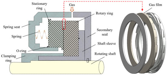
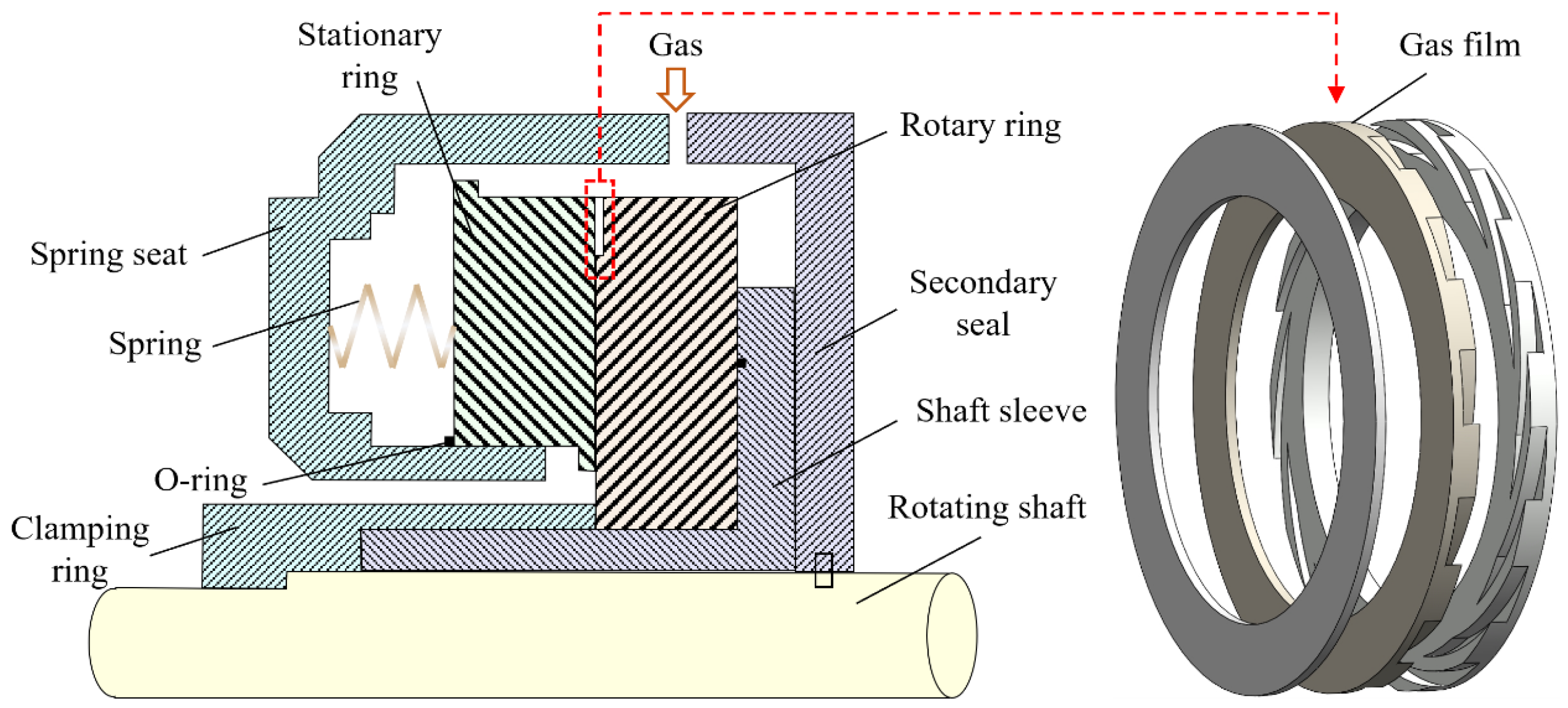
During operational engagement of the DGS system, the rotating shaft drives the rotary ring to rotate, and the sealing gas enters the sealing groove [13]. The sealing gas has low viscosity and high pressure, and a gas film is formed between the two sealing surfaces [14]. The gas film can separate the sealing surface and play the role of sealing and lubrication [15], as shown in Figure 1.
Figure 1.
Working principle of the DGS system.
The closing force results from the tension of the spring and the pressure of the medium. The opening force is formed by the dynamic pressure generated by the sealing gas and the static pressure on the sealing surface. The stationary ring is subjected to both opening force and closing force. Under ideal conditions, the stability of the sealing system is ensured by maintaining a balance between the opening force and closing force. In the event of internal or external disturbances (such as abrupt pressure fluctuations) disrupting the balance between the opening and closing forces within the sealing gas film, the system autonomously adjusts the sealing gap to restore balance [16,17]. Operational stability in dry gas sealing systems is ensured by their inherent self-regulating mechanism [18]. However, when they are used under severe working conditions, problems such as an unstable gas film, friction of seal surface, and high leakage rate may occur. These factors will affect the performance of the DGS, the direct consequence of which is a reduction in the stability of the system, as well as its service life [19,20].
The hydrodynamic lift, leakage control, and mechanical stability in liquid hydrogen applications can be balanced by optimizing the structural design parameters of the DGS, such as groove geometry [21], sealing gap [22], and surface topography [23,24]. Gabriel [25] conducted a comprehensive study of spiral groove dry gas seals, quantifying the interdependency between sealing performance and critical variables in both operational conditions and structural designs. The dry gas seal with the spiral groove (S-DGS) generated substantial dynamic forces through its spiral grooves, resulting in enhanced gas film stiffness and superior sealing performance. This design structure remains the archetype and most prevalent in applications. Chen et al. [26] demonstrated that the influence of structural variables on the operational property of S-DGSs is complex and dependent. Design parameters were optimized via neural network modeling, achieving a prediction error margin below 3.6% and demonstrating enhanced sealing efficiency.
Different geometric structures can produce different dynamic pressure effects, which influence the sealing and reliability of DGSs [27,28]. Variations in groove dimensions critically determine sealing efficiency through their impact on gas film stiffness and flow dynamics. Using the finite difference method, Jiang et al. [29] were inspired by bird wing morphology and developed biomimetic groove structures, including cluster, multi-array and flow-split spiral shapes, to enhance the static sealing characteristics. Cluster spiral groove DGSs exhibited a 20% higher gas film rigidity and 50% greater leakage flow compared to conventional S-DGS structures. Chen et al. [30] proposed a super-elliptic curve groove, which demonstrated the coupling mechanisms between gas film stiffness and dynamic tracking precision in sealing systems. It was revealed that a fixed-angle dynamic gap is formed between sealing interfaces under angular excitation inputs, which had a serious influence on the transient characteristics of the DGS.
A change in the operating environment affects the flow characteristics of the sealing gas. Therefore, the sealing and stability of DGSs are affected [31,32]. Yan et al. [33] established the critical dependence of gas film dynamic behavior on rotational speed and pressure differentials through simulation and experimental methods. At low speed and low pressure, a laminar flow occurs within the thin gas layer. With elevated rotational velocity and pressure conditions, the gas film flow transitions into a turbulent regime, resulting in a marked increase in leakage rate. Jiang et al. [34] introduced a triangular-based generalized geometric model to describe spiral grooves and established a mathematical model. Through the finite difference method, optimal spiral grooves under low-speed working conditions were obtained, and the gas film exhibited a 15% enhancement in stiffness compared to conventional S-DGSs. Du et al. [35] conducted a multi-physics coupling analysis incorporating thermal, fluid, and solid interactions, revealing that the rotational velocity of the sealing ring exerts a substantial influence on interface sealing efficiency, particularly under conditions of increased film thickness.
The operating conditions for the application of DGSs are becoming more and more complex, which generates higher demand for the design of face grooves [36,37]. Recently, more complex bionic and composite groove designs have been explored to further enhance the hydrodynamic effects of DGSs. However, most existing studies typically focus on the optimization of a single specific groove type. There is a lack of a unified comparative framework that evaluates different bionic and industrial groove morphologies under identical geometric constraints to isolate the shape effect from the volume effect. In this study, five different groove structures are selected. By designing the same groove volume, the sealing gas volume is guaranteed to be consistent. Under this premise, the performance of different groove structures is analyzed and compared with the traditional S-DGS structure. The relationship between the working conditions and sealing performance of different groove structures was studied. This study provides guidance for the design of sealing systems under severe working conditions.
2. Materials and Methods
2.1. Physical Model
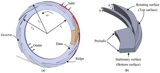
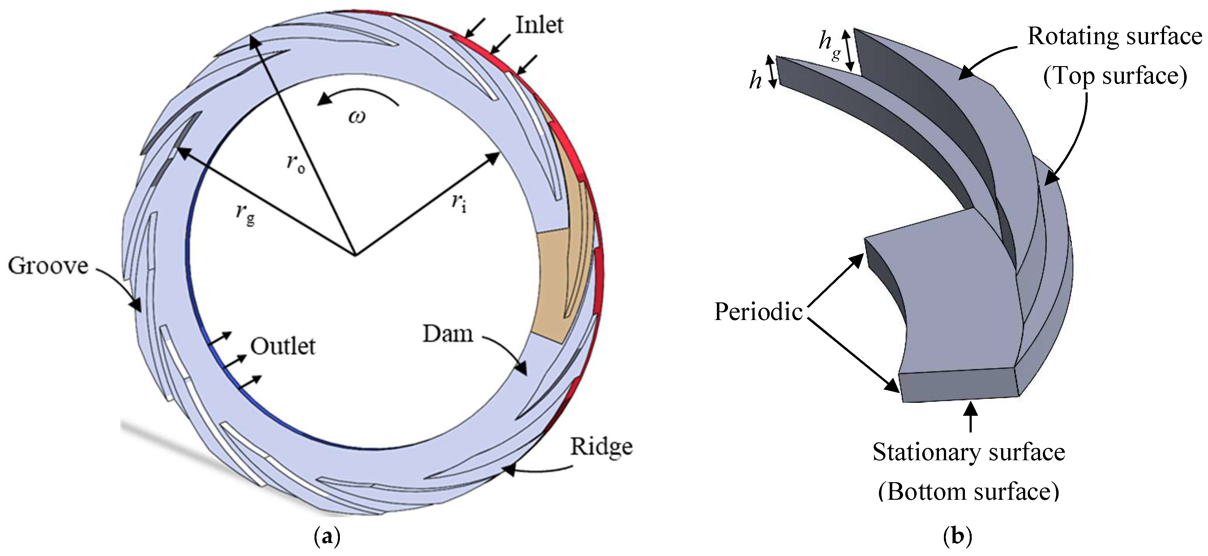
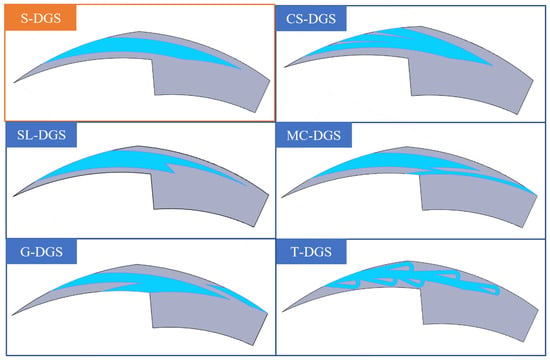
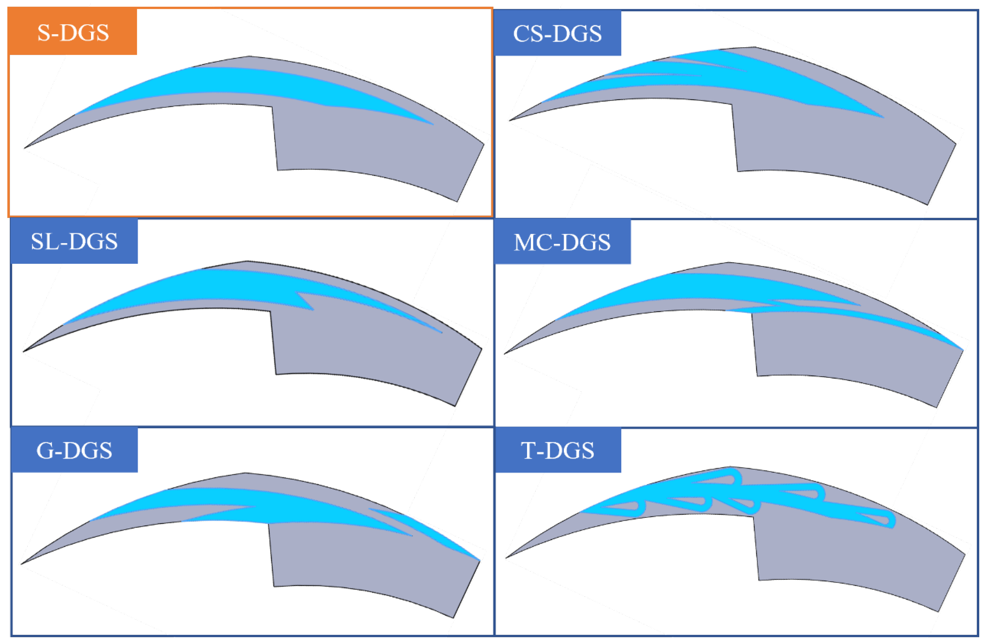
The typical DGS groove structure is spiral in shape, with 12 spiral grooves forming a circle. In this study, one groove is selected for simulation, as shown in Figure 2. In addition, this paper selects the cluster spiral groove DGS (CS-DGS) presented by Jiang et al., the swallowtail-like groove DGS (SL-DGS) of the Dresser-Rand Company, the multi-combined spiral groove DGS (MC-DGS) from the Flowserve Company, the goose groove DGS (G-DGS) of the Antoni Company, and the Tesla groove DGS (T-DGS) proposed by Wang et al. [38], as displayed in Figure 3.
Figure 2.
Geometric model. (a) complete geometric model, (b) geometric model of simulation (1/12).
Figure 3.
Groove structures.
To ensure the comparability of the six different groove structures, a constant area ratio principle is applied during the geometric modeling. The primary constraint is that the area ratio between the groove and the ridge is fixed at 1:1 for all models. This ensures that the total volume of the fluid film and the effective hydrodynamic pressure-generating area remain equivalent across all structures, allowing for a focused investigation on the effect of groove structure rather than size. The main structural parameters are given in Table 1.
Table 1.
Geometric parameters.
2.2. Mathematical Model
The following assumptions are made based on the physical characteristics of the DGS [25,33]: (1) The gas film thickness is in the microscale, resulting in a very low Reynolds number, so the state of the sealing gas in the operating condition is laminar flow. (2) For the gas medium under the investigated conditions, the pressure variation caused by centrifugal force is significantly smaller than the hydrodynamic pressure generated by the grooves; thus, the centrifugal effect is not considered. (3) The sealing gas is treated as an ideal gas, and the lubrication process is assumed to be isothermal. (4) No-slip boundary conditions are applied at the gas–solid interfaces.
The pressure within Newtonian compressible fluids under viscous flow conditions is derived through analytical solution of the steady state Reynolds equation of compressible flow [33]:
where p is the pressure, h is the local film thickness, μ is the viscosity, ω is the angular velocity, ρ is the density, r is the radius, and θ is the angle.
The thickness of the gas film between the seal faces can be calculated as follows:
where h0 is the film thickness, and hg is the groove thickness.
Pressure boundary conditions are as follows:
where pi is the inlet pressure, and po is the outlet pressure.
Periodic pressure boundary conditions are thus:
The operating conditions are set as shown in Table 2.
Table 2.
Operating conditions.
The opening force F0 is the gas film pressure that separates the faces of the rotary and stationary ring seals during the running of the DGS system. The calculation formula is [8]:
Leakage rate Q serves as a critical performance metric to evaluate the property of the DGS system. The calculation formula is:
2.3. Numerical Method
The governing equations were discretized using the Finite Volume Method (FVM). The Second-Order Upwind scheme was employed for the discretization of the momentum equations to ensure numerical accuracy and stability. The SIMPLE algorithm was adopted for the pressure–velocity coupling. Furthermore, the convergence criteria for the residuals of all solved equations were set to 10−5, and the inlet and outlet mass flow rate were monitored to ensure they reached a steady state.
2.4. Reliability Verification
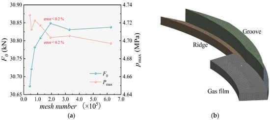
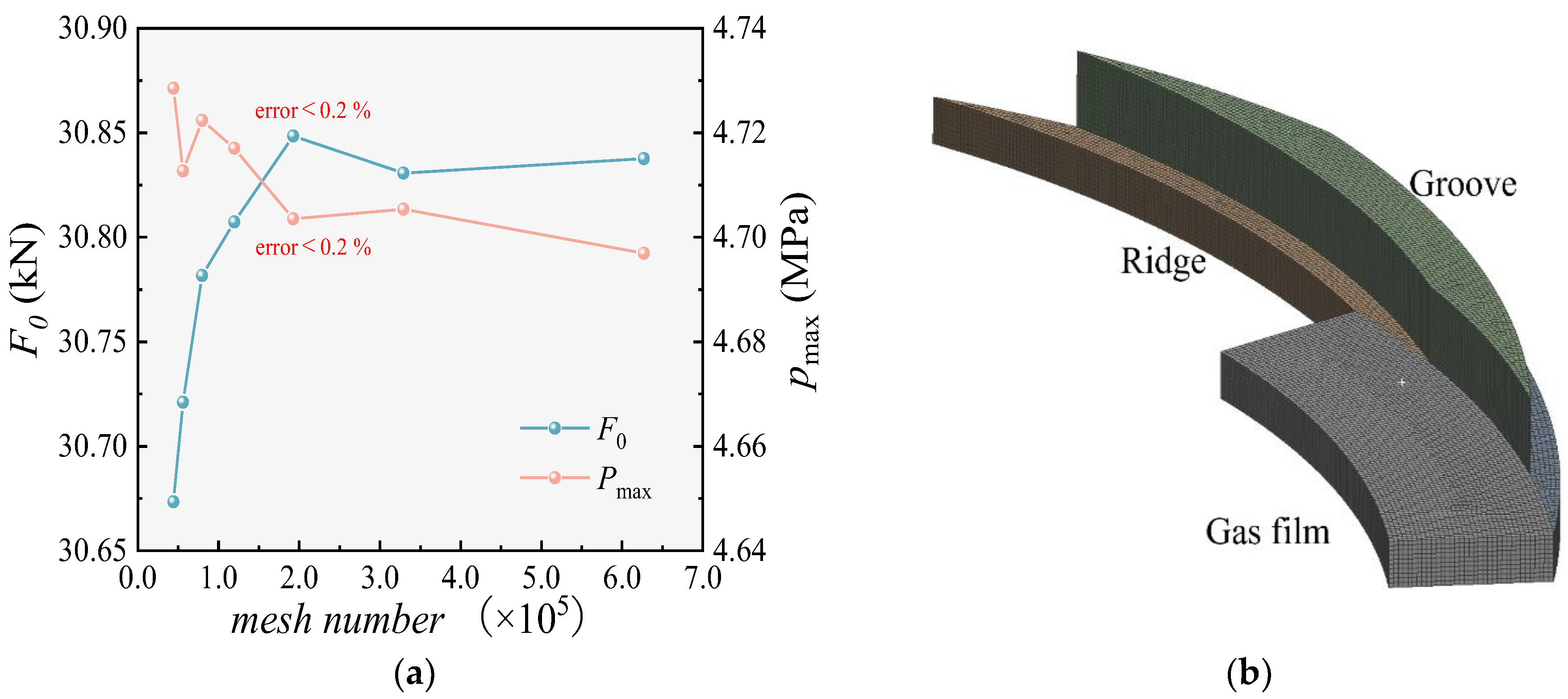
To determine the mesh size with the highest computational efficiency and verify its reasonableness, the mesh was divided into seven different sizes. The total number of elements corresponding to the mesh sizes of 0.5 mm, 0.45 mm, 0.4 mm, 0.35 mm, 0.3 mm, 0.25 mm, and 0.2 mm were 44,185, 55,988, 79,619, 119,634, 192,511, 329,082, and 626,961, respectively. The sealing property of the S-DGS at an inlet pressure of 4.5852 MPa and a rotational velocity of 10,380 rpm was simulated. Figure 4a represents the opening force and maximum pressure.
Figure 4.
(a) Independent mesh verification, and (b) grid division diagram.
The goal parameters tended to be stable when the mesh size was 0.3 mm and the number of elements was 192,511. Taking the simulation results of the 0.2 mm mesh as a reference for error analysis, it can be found that when the number of meshes reaches 192,511, the relative error is less than 0.2%, which is within a reasonable range. To ensure the dependability of the results while improving the calculation speed, this study chooses to divide the model mesh into 0.3 mm, as shown in Figure 4b.
The relative error δ is calculated to evaluate the convergence, defined as:
where Resulti is the simulation results of the 0.5 mm, 0.45 mm, 0.4 mm, 0.35 mm, 0.3 mm, and 0.25 mm meshes, and Result0 is the simulation results of the 0.2 mm mesh.
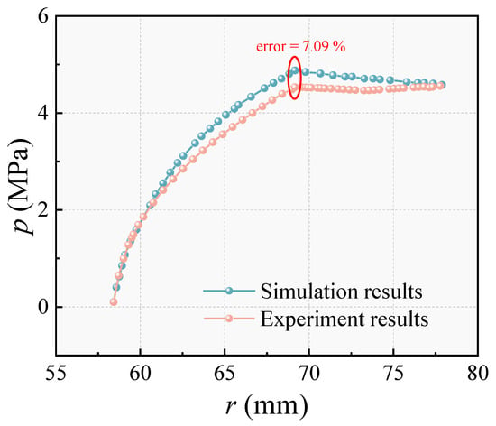
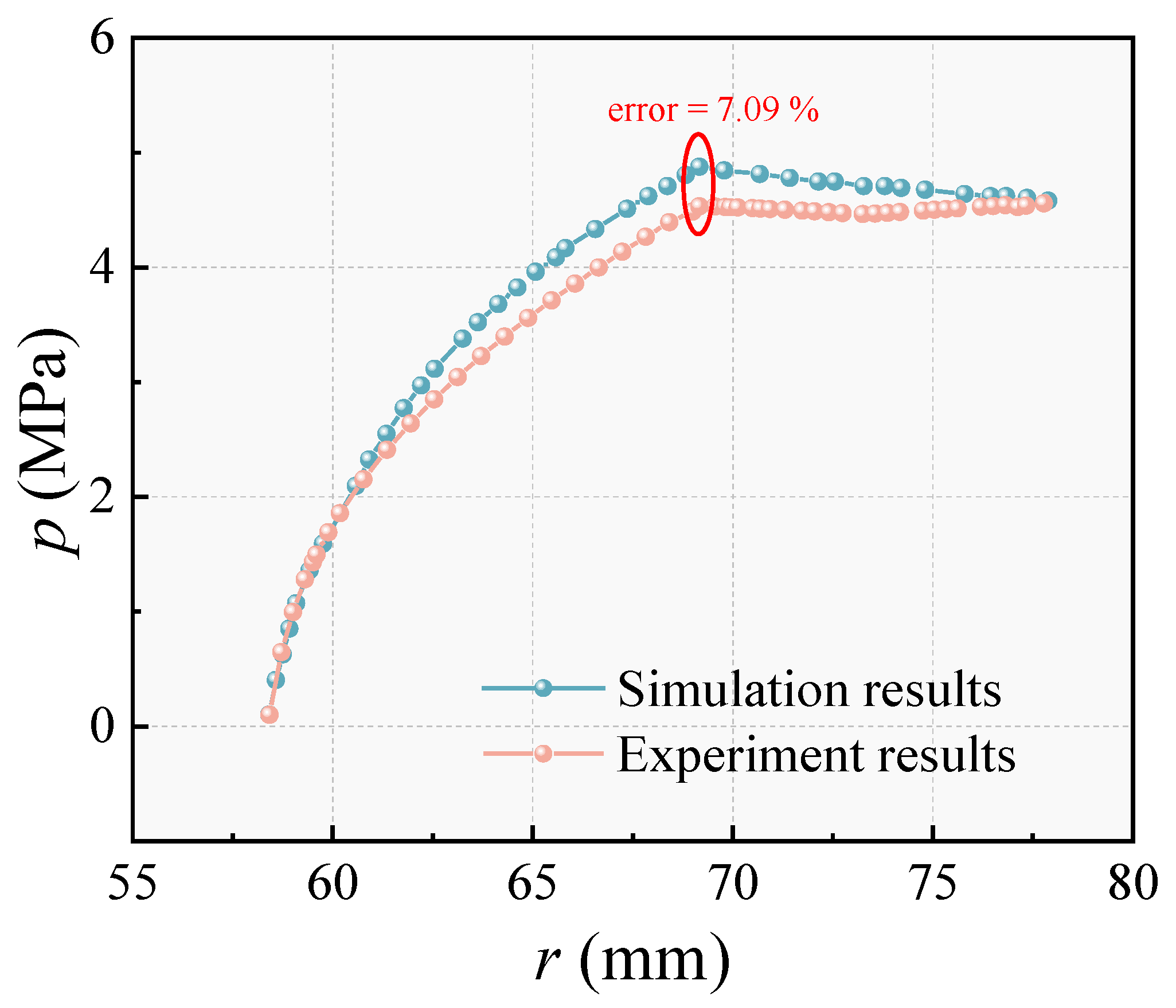
Figure 5 compares the pressure along the radial direction obtained from the simulation with the experimental data of Fairuz et al. [39]. It is found that the maximum error is located at the root of the groove, about 7.09%, which is within reasonable limits. It can be concluded that the selected simulation model is reliable and the results have reference value.
Figure 5.
Model verification [39].
3. Results and Discussion
3.1. The Influence of Groove Structure
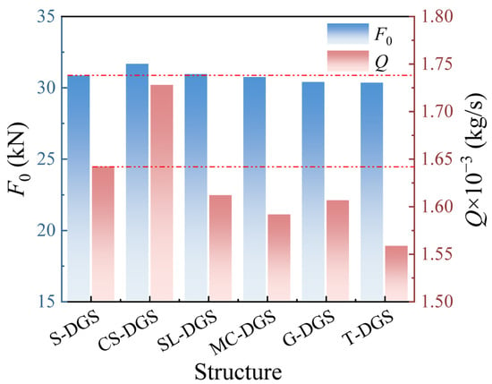
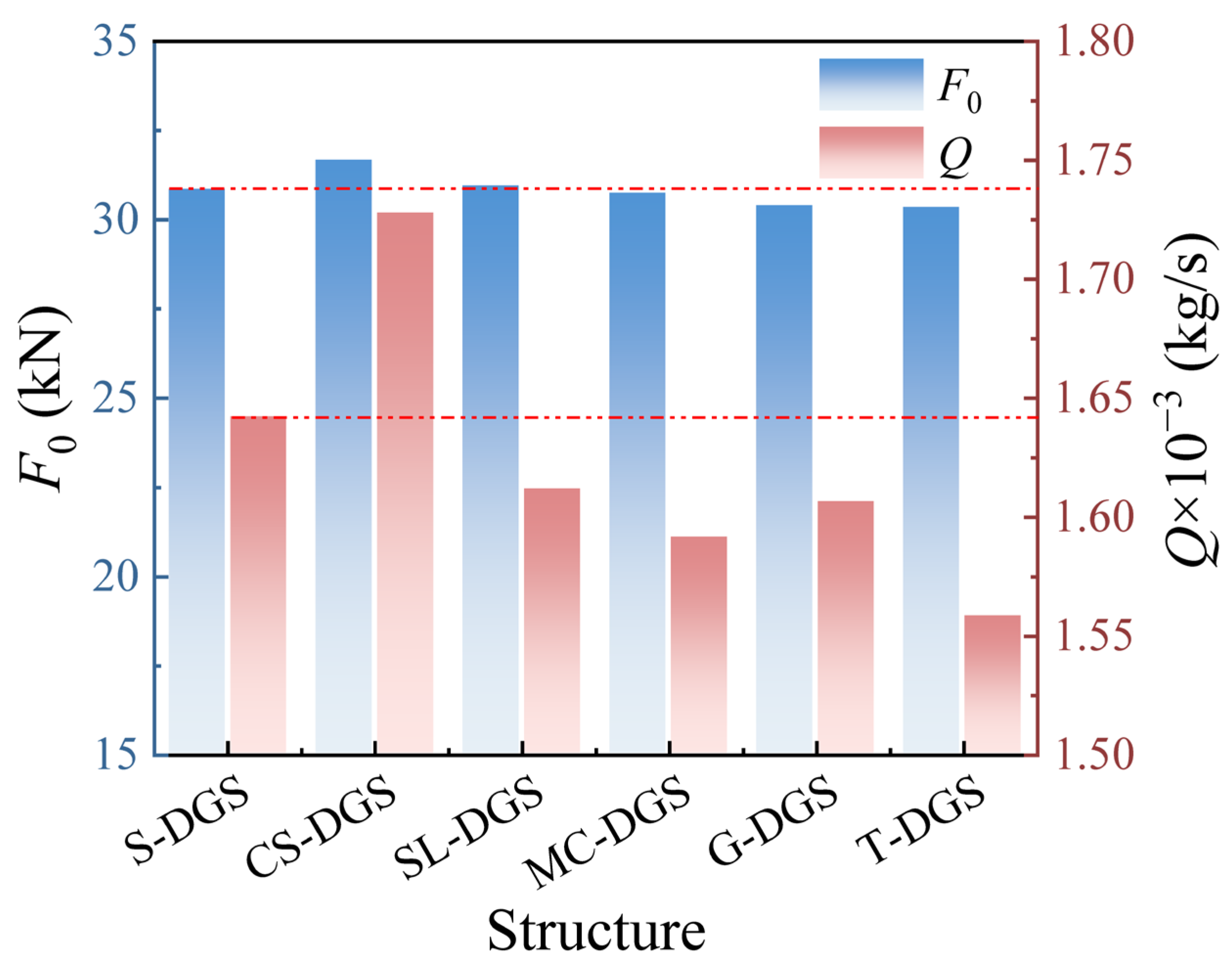
Simulations were conducted on six DGS grooves with varied groove geometries under operational parameters of 4.5852 MPa inlet pressure and 10,380 rpm rotational speed. Figure 6 presents the opening force (F0) and leakage rate (Q) for the same volume of sealing gas. The results indicate a clear correlation between groove structure and performance. Comparative analysis reveals that the CS-DGS exhibits a 2.66% enhancement in opening force compared to the S-DGS, while demonstrating a concomitant rise in leakage of about 5.24%. This design prioritizes frictional contact mitigation at the rotor–stator interface through microscale gas film maintenance, thereby improving the dynamic pressure effect while compromising sealing efficiency under transient operational conditions. Compared with the traditional S-DGS system, MC-DGSs, G-DGSs and T-DGSs have better sealing performance, but the opening force generated by the sealing gas is smaller. The opening force is reduced by 0.36%, 1.48% and 1.62%, and the leakage rate can be reduced by up to 3.08%, 2.17% and 5.11%, respectively. The T-DGS achieves the minimum leakage rate. This superior sealing efficiency is due to the inherent unidirectional flow resistance characteristic of Tesla geometry, which creates a significant reverse pressure gradient that impedes the radial outflow of the sealing gas. Compared with the S-DGS, the SL-DGS achieves a dual enhancement in gas film pressure and sealing efficiency. Leakage reduced by 1.84% and opening force increased by 0.32%. This is because the structure concentrates the high-pressure area at the root of the groove and uses a swallowtail-like groove to change the direction of the secondary flow. SL-DGSs maintain the stability of the gas film while ensuring its sealing performance.
Figure 6.
Opening force and leakage of DGSs with different groove structures (pi = 4.5852 MPa, ω = 10,380 rpm).
The transport of gas sealing medium arises from synergistic interactions between radially oriented pressure gradients and circumferential viscous shear effects. The gas enters the groove and is squeezed at the dam area, resulting in fluid dynamic pressure effects and forming a high-pressure area at the root of the groove. High-pressure gas drives the stationary ring to compress in the direction of the spring. A gas film is generated between the rotatory and stationary rings to provide a sealing effect [40].
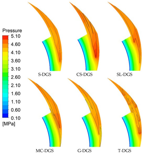
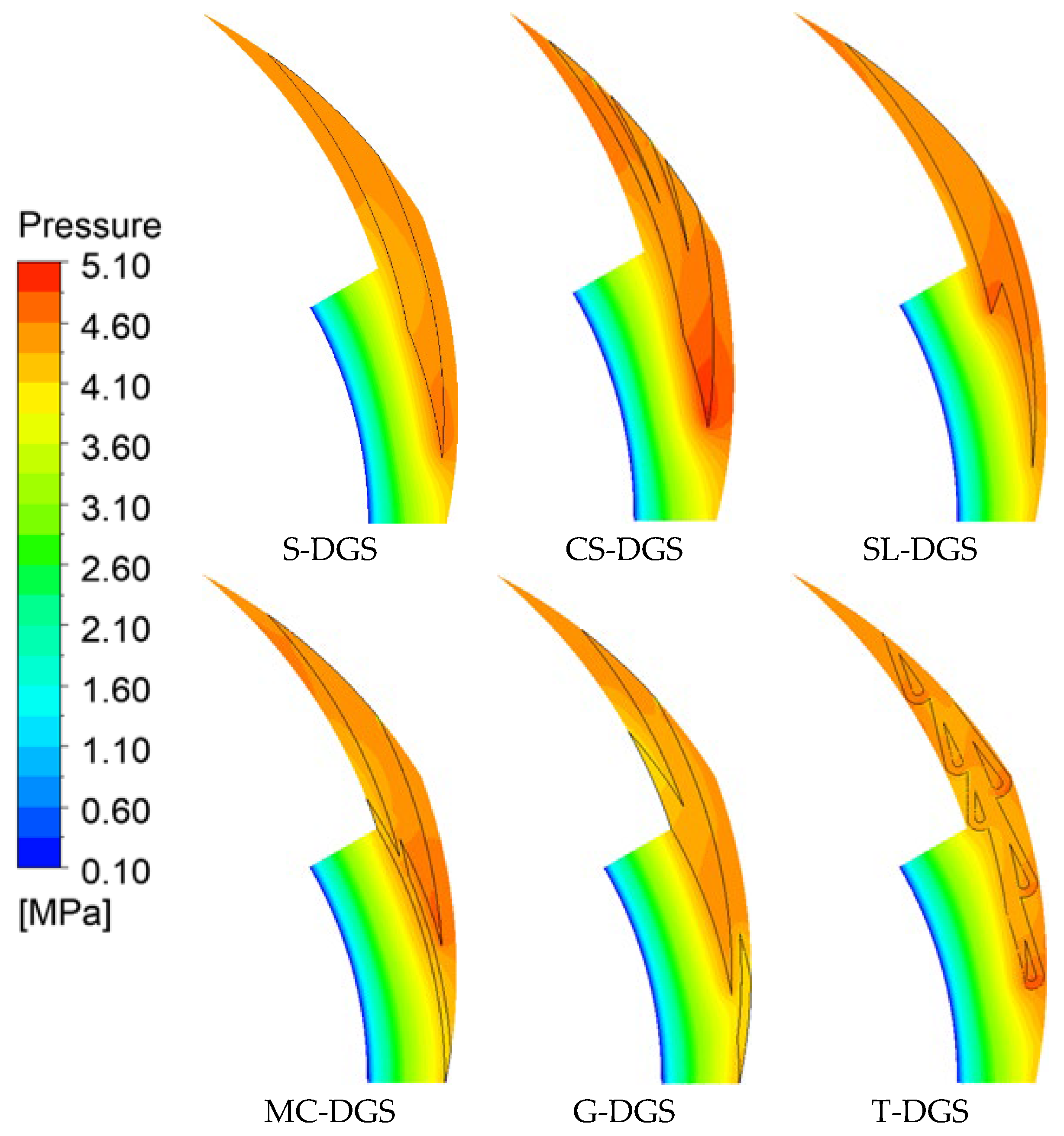
Figure 7 shows the pressure profile. The pressure of the sealing dam is less than that of the groove ridge area. Rotary ring groove roots exhibit maximum pressure concentration. CS-DGS, SL-DGS, MC-DGS and T-DGS systems show greater pressure at the root of the rotary ring groove than the S-DGS system. This phenomenon demonstrates that the grooves of the CS-DGS and SL-DGS have a better guide effect on gas, as the resistance of the gas encountered in the rotation process is smaller. Therefore, the pressure of the groove part is larger and more evenly distributed. The sealing gas reaches the groove root more smoothly and is compressed, so the rotary ring groove root pressure is higher than in the S-DGS. The pressure difference between the rotary ring groove root and the inside of the groove is smaller. The overall pressure of the groove is high, resulting in a large opening force.
Figure 7.
Film pressure contours of DGSs with different groove structures (z = 1/2 h0).
As is shown in Figure 7, the pressure at the groove root of the MC-DGS is greater than that of the S-DGS. However, the presence of the inner ring reduces the overall pressure. As a result, the opening force is slightly lower. During the working process, the groove structure of the T-DGS is more complex, and there is a large flow resistance. There are multiple flow dead zones, creating a high-pressure gas zone. The overall pressure distribution is uneven, resulting in a low opening force. The G-DGS has a lower groove root pressure and produces a smaller dynamic pressure effect. Even if the goose groove allows for a more uniform gas pressure distribution, it will not produce a large opening force.
The low-pressure area in the groove structure can suck in the surrounding gas. The sealing gas is driven to the low-pressure area, which reduces the leakage. The pressure difference in SL-DGS, MC-DGS, G-DGS and T-DGS groove parts is greater than that of the S-DGS, so that the leakage of sealing gas is less than that in the S-DGS. Among them, the pressure gradient in the groove area of the T-DGS is larger, the suction effect is the most obvious, and the leakage rate is the smallest. The SL-DGS demonstrates optimal comprehensive characteristics through the coordinated reinforcements of aerodynamic action and sealing property. The CS-DGS groove structure has a much greater guiding effect on the sealing gas than the suction effect caused by pressure difference. Therefore, although there is a pressure difference in the groove, the leakage rate is still greater than that of the S-DGS.
3.2. The Influence of Rotary Ring Speed
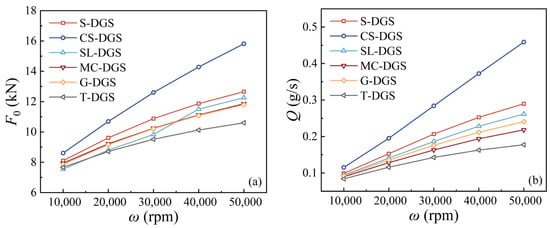
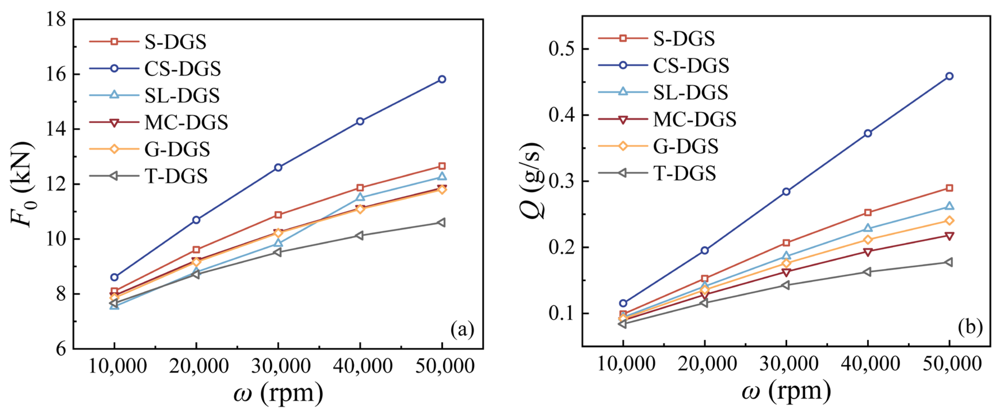
In Figure 8, as the rotary ring speed grows, the dynamic effect of the gas medium increases. The shear drive mechanism causes more seal gas to enter the seal face from the grooves. Consequently, the opening force of the DGSs increases and the leakage grows. The opening force and leakage are proportional to the speed of the rotary ring. As the speed grows, the dynamic effect produced by the groove-induced fluid becomes dominant. The results indicate that under high-speed conditions, the performance of dry gas seals is more closely related to the groove structure. The F0 of the S-DGS, CS-DGS, MC-DGS, G-DGS and T-DGS systems displays the same trend with changes in rotary ring velocity. The growth rate of the opening force gradually reduces as the speed of the rotating ring grows. The opening force increases by 56.21%, 83.81%, 49.33%, 50.23% and 38.33%, respectively, when the rotary ring speed increases from 10,000 rpm to 50,000 rpm, as shown in Table 3. The speed of the rotary ring has the greatest influence on the opening force of the CS-DGS, indicating the presence of strong dynamic effects, but accompanied by a sharp increase in leakage, it becomes difficult to control at ultra-high speeds. The opening force of the SL-DGS is the smallest when the rotary ring speed is 10,000 rpm. When speed reaches 50,000 rpm, the opening force is greater than that of the MC-DGS. When the speed of the rotary ring increases from 30,000 rpm to 40,000 rpm, the impact on the opening force of the SL-DGS is the largest, which can increase by up to 16.97%. This is because the SL-DGS has two groove roots: as the speed changes from 30,000 rpm to 40,000 rpm, the pressure accumulation at the twin groove roots intensifies significantly, allowing the dynamic pressure effect to play a leading role in performance enhancement.
Figure 8.
Opening force and leakage of DGSs with different groove structures (pi = 1 MPa). (a) Opening force; (b) leakage rate.
Table 3.
The growth rate of F0 and Q with different rotary ring speeds (pi = 1 MPa).
It is found from Figure 8b that the rotary ring speed has the greatest influence on the leakage rate of the CS-DGS. The relationship between the two is approximately linear. When the rotary ring speed increases from 10,000 rpm to 50,000 rpm, the leakage rate will increase by three times. The leakage rates of the S-DGS, SL-DGS, MC-DGS, G-DGS and T-DGS systems are consistent with the relationship between the speed of the rotary ring. When the rotary ring speed increases from 10,000 rpm to 50,000 rpm, the leakage rates increase to 190%, 178%, 144%, 162% and 111%, respectively. It can be concluded that the overall performance (high opening force and manageable leakage) of the SL-DGS is greatly improved when the speed of the rotary ring reaches 40,000 rpm.
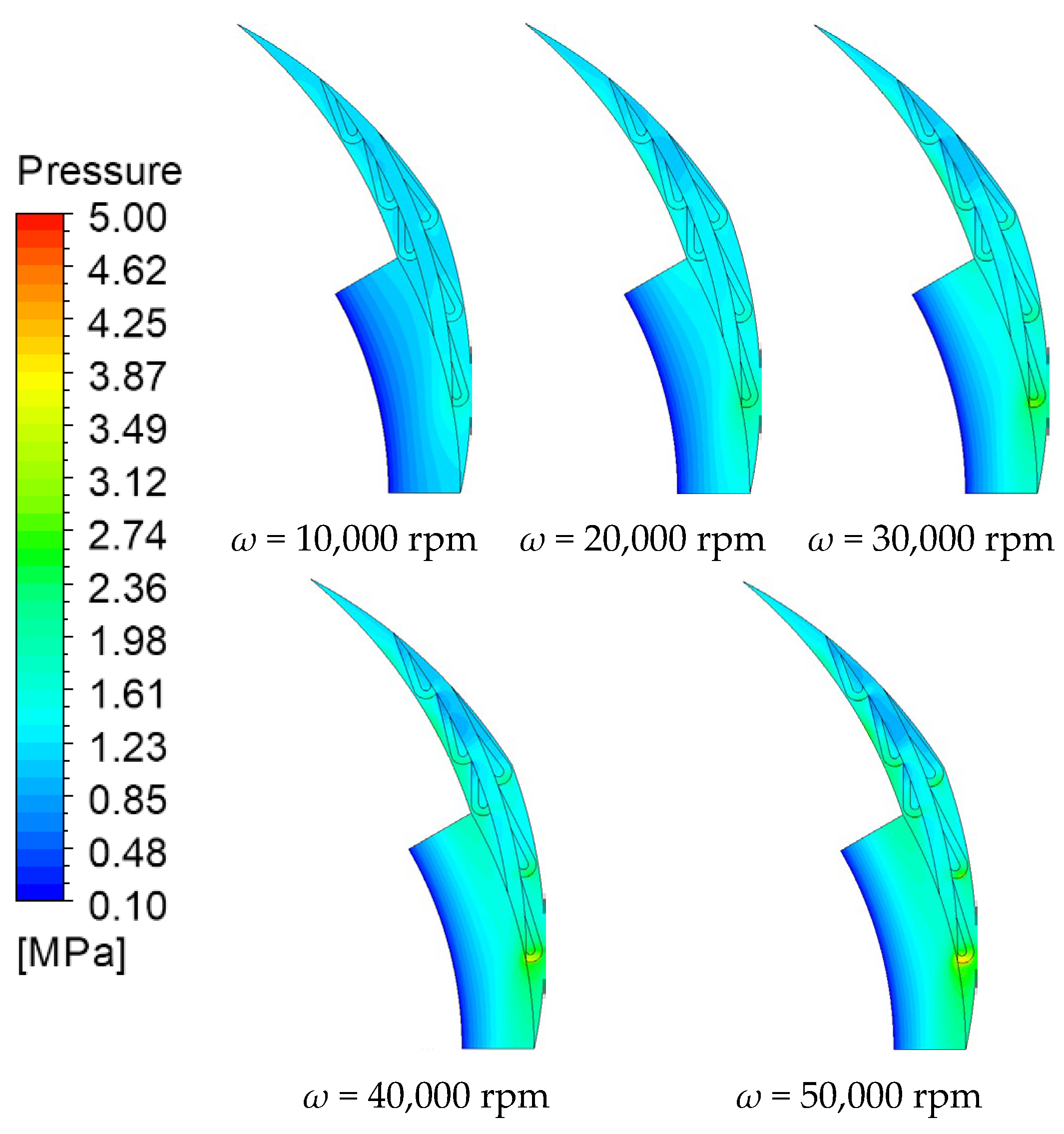
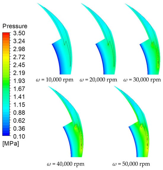
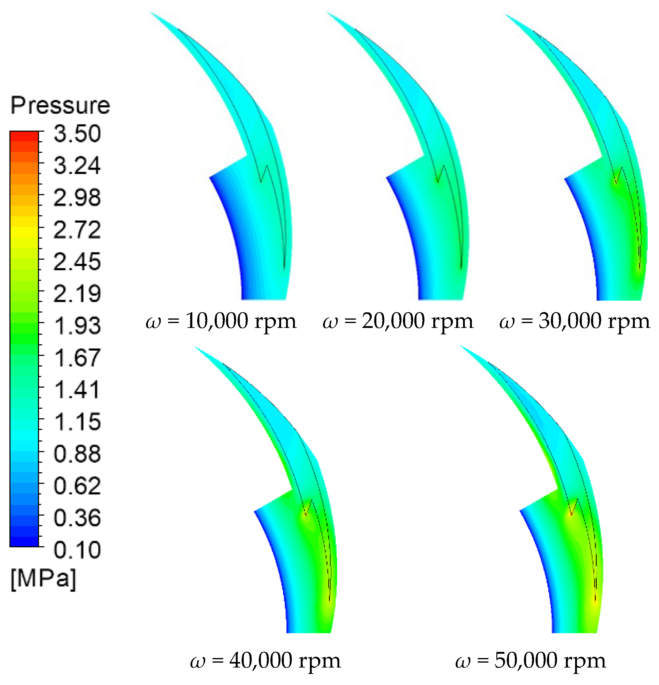
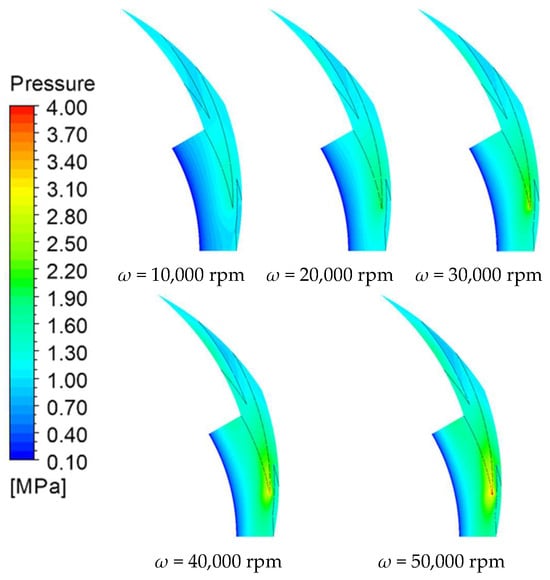
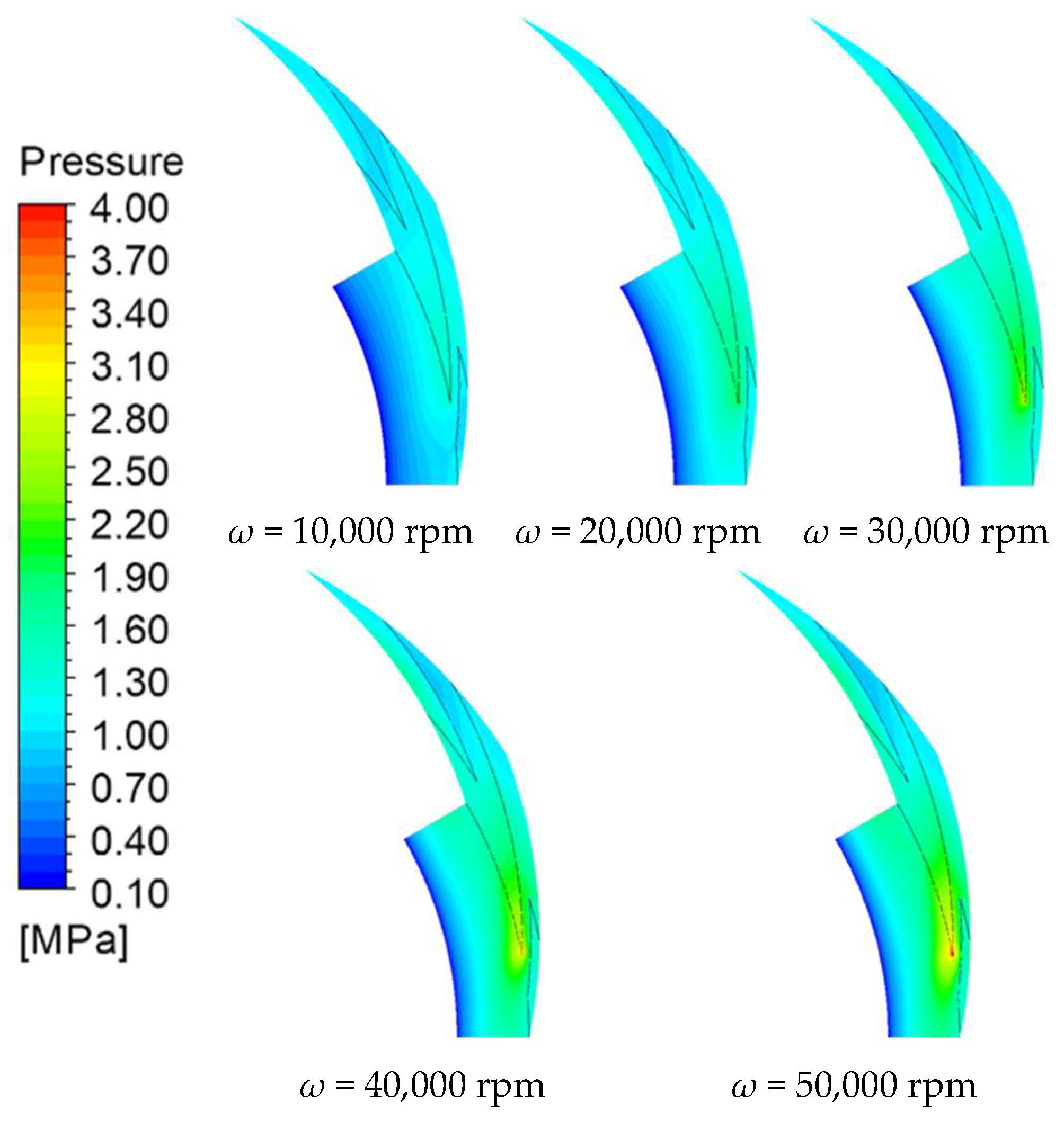
Figure 9 and Figure 10 illustrate the pressure distribution of the SL-DGS and G-DGS systems at different rotational speeds (z = 1/2 h0, pi = 1 MPa). It can be clearly observed that the overall pressure of the two DGSs is positively correlated with speed. However, the pressure distribution of the gas film becomes more and more uneven. It can be concluded that incremental increases in rotational speed will gradually reduce the stability of the gas film. When internal and external disturbances occur on the sealing end face, there may be an area of low pressure between the rotary and stationary rings. Failure to produce a gas film with a certain thickness may cause the two rings to come into contact with each other and generate friction, resulting in damage to the sealing end face and reducing the efficiency and lifespan of the operating system. Combined with the analysis of Q for DGSs, the uniformity of pressure distribution decreases and the pressure gradient between the outside and the root of the groove is positively correlated with the speed. An increase in pressure gradient can cause gas to be drawn into the groove, but it still cannot reduce the leakage rate. The pressure contours of the other four structures (S-DGS, CS-DGS, MC-DGS, and T-DGS) exhibit similar distribution patterns and are provided in Appendix A for reference (Figure A1, Figure A2, Figure A3 and Figure A4).
Figure 9.
The gas film pressure contours of the SL-DGS under different rotational speeds (z = 1/2 h0, pi = 1 MPa).
Figure 10.
The gas film pressure contours of the G-DGS under different rotational speeds (z = 1/2 h0, pi = 1 MPa).
The aerodynamic action from the seal gas is the dominant mechanism effecting the opening force of the DGS. The pressure at the groove root of the G-DGS is larger than that of the SL-DGS; however, the SL-DGS has two groove roots, with a large proportion of high-pressure zones and a strong dynamic pressure effect of sealing gas. In addition, the opening force of the SL-DGS is highly sensitive to the speed of the rotating ring. It can be concluded that the coupling of the maximum pressure in the groove and the overall distribution of the pressure affects the opening force of the DGS.
3.3. The Influence of Inlet Pressure
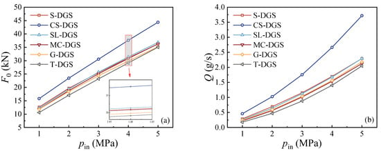
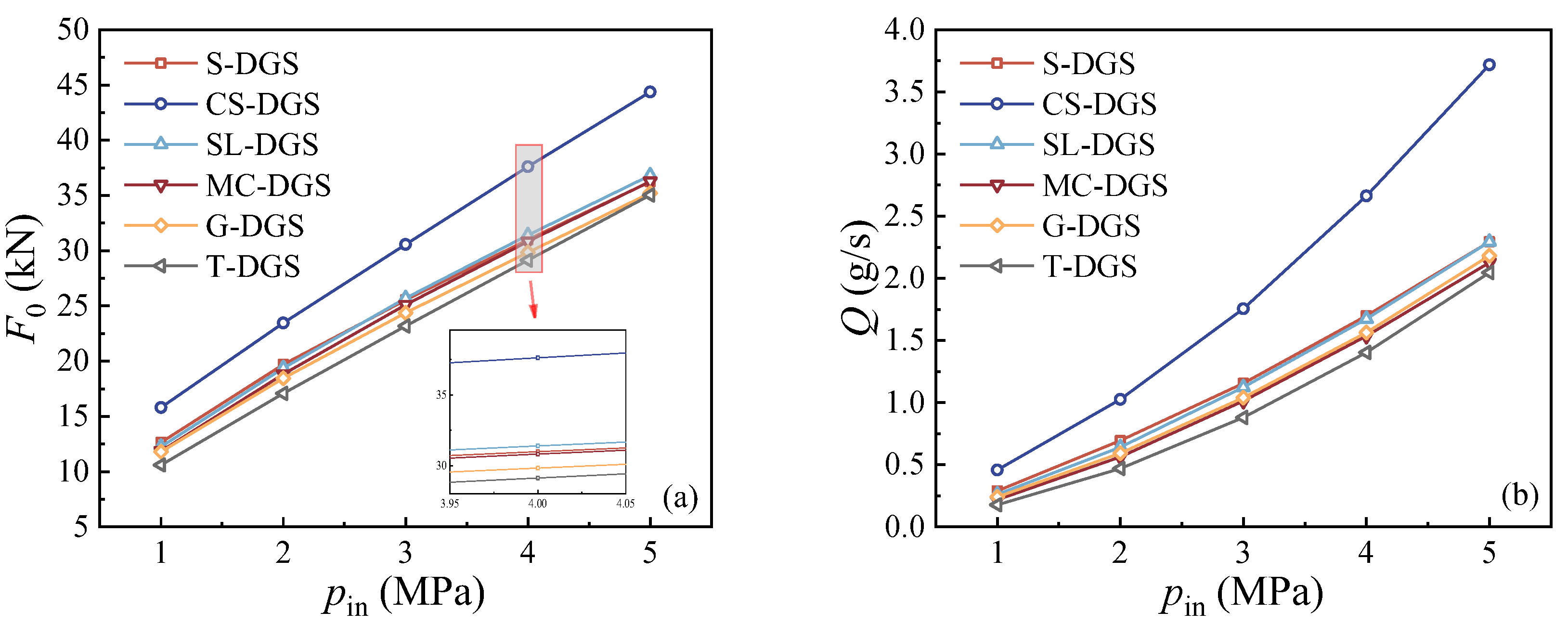
Figure 11 presents the variation in F0 and Q of the DGSs with inlet pressure (ω = 50,000 rpm). The opening force of the six DGSs is approximately linearly positively correlated with the inlet pressure. Increasing the inlet pressure is beneficial for forming a gas film pressure. The groove root pressure is positively correlated with inlet pressure. A higher inlet pressure increases the overall pressure of the groove, leading to an increase in DGS opening force. Under 1 MPa inlet pressure, the T-DGS has the largest increase in opening force of 10.60 MPa. The pressure can reach 35.04 MPa when the inlet pressure achieves 5 MPa, which is 3.3 times greater than the original. The F0 of the S-DGS, CS-DGS, SL-DGS, MC-DGS and G-DGS systems can be increased by 186%, 181%, 200%, 206% and 198%, respectively, when the inlet pressure increases from 1 MPa to 5 MPa, as shown in Table 4.
Figure 11.
The relationship between the opening force and leakage rate of DGSs with inlet pressure (ω = 50,000 rpm). (a) Opening force; (b) leakage rate.
Table 4.
The growth rate of F0 and Q with different inlet pressures (ω = 50,000 rpm).
Observing Figure 11b, the leakage rate of the six DGSs follow the same trend as the pi. As the pi grows, the change rate of the leakage rate gradually increases. Their relationship is approximately exponential, indicating that the Q is highly sensitive to the inlet pressure. It can be concluded that the Q of the T-DGS will increase by 11.5 times when the inlet pressure increases from 1 MPa to 5 MPa. When the inlet pressure is 5 MPa, the Q of the SL-DGS is basically the same as that of the S-DGS.
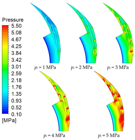
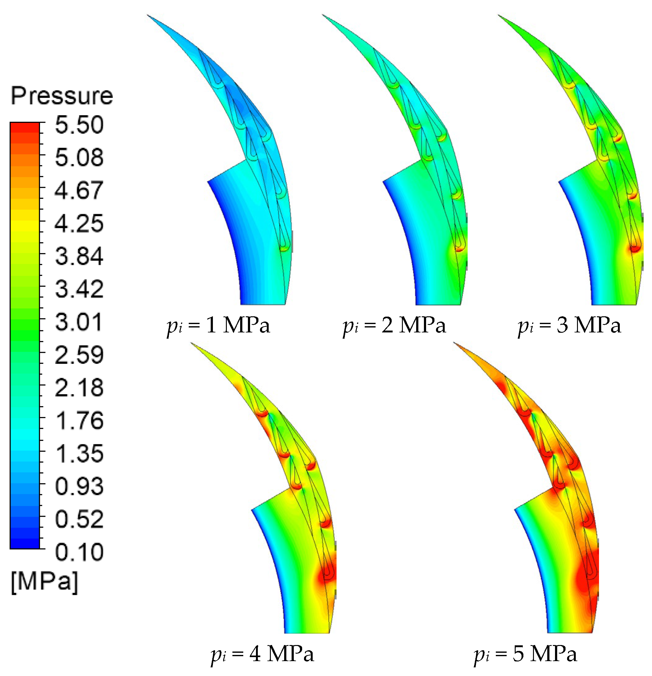
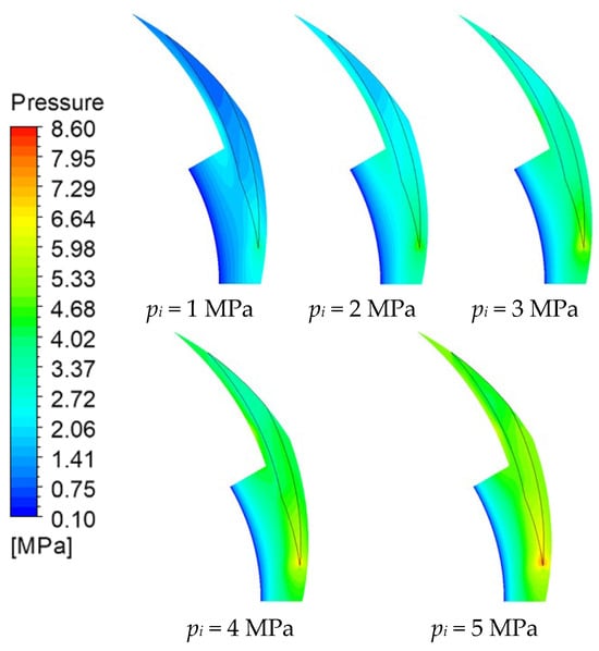
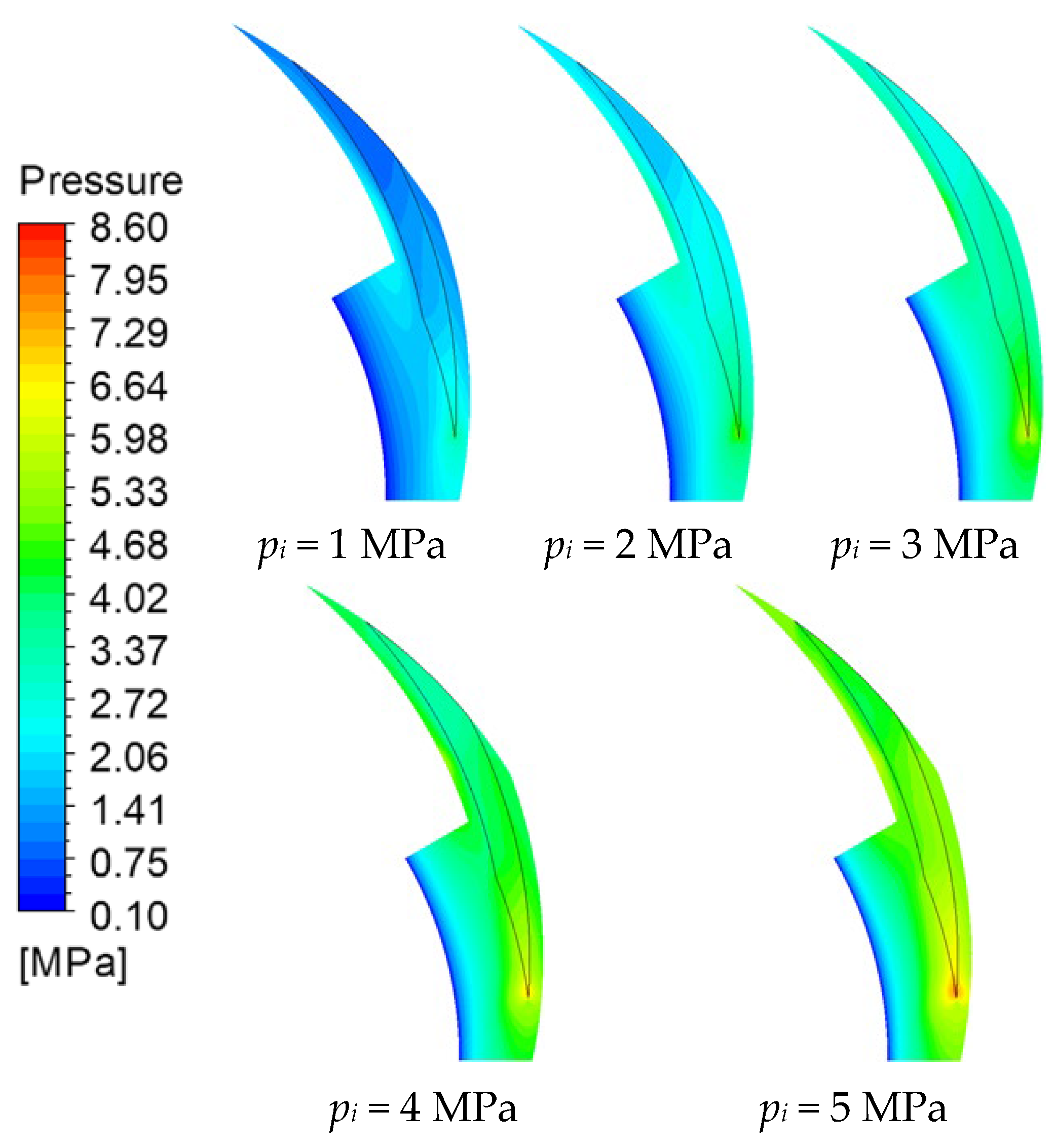
Figure 12 presents the pressure contours of the T-DGS under different inlet pressure conditions. It can be observed that as the inlet pressure increases, the overall pressure level of the gas film rises significantly. Specifically, the peak pressure at the tip and trailing edge of the grooves increases sharply. The Tesla-shaped groove structure exhibits a strong blocking and accumulation effect on the high-pressure gas. As pi increases, the pressure gradient across the seal face steepens, leading to a much more pronounced enhancement of the hydrodynamic effect compared to other structures. As a result, the T-DGS has the highest sensitivity to inlet pressure, resulting in the rapid growth of both opening force and leakage rate.
Figure 12.
The gas film pressure contours of the T-DGS under different inlet pressures (z = 1/2 h0, ω = 50,000 rpm).
Compared with other groove structures, the inlet pressure has minimal impact on the F0 of the S-DGS. Under the condition that the inlet pressure is less than 4 MPa, the aerodynamic action of the gas in the S-DGS is just second to that of the CS-DGS. As the inlet pressure reaches 4 MPa, the F0, due to the dynamic pressure effect of the S-DGS, is also smaller than that of the SL-DGS. Figure 13 illustrates the film pressure contours of the S-DGS under different inlet pressure conditions. It can be clearly seen that when the inlet pressure is 1–3 MPa, the root pressure of the groove grows and the uniformity of the pressure in the groove area increases. This indicates a gradual increase in opening force. When the inlet pressure reaches 4 MPa, the pressure change in the groove area is small, so the opening force increases to a lesser extent.
Figure 13.
The gas film pressure contours of the S-DGS under different inlet pressures (z = 1/2 h0, ω = 50,000 rpm).
From Figure 13, it can be observed that the uniformity of pressure distribution improves as the inlet pressure increases. The area of low-pressure zones decreases, and the system’s ability to cope with internal and external disturbances increases. The stability of the sealing system is better. Meanwhile, the pressure gradient of the gas film becomes smaller, and the suction effect of the gas gradually weakens. The pressure at the root of the groove has a monotonically increasing relationship with the pi, and the dynamic pressure effect of the gas gradually grows. Sealing gas is highly sensitive to pi, and an increase in pi leads to an increase in Q. When the pressure increases from 1 MPa to 5 MPa, the leakage of the S-DGS will increase by eight times.
3.4. Comprehensive Discussion
Table 5 presents a comprehensive comparative analysis of the six structures with regard to increases in rotary ring speed and inlet pressure. The performance ranking is: Optimal > Excellent > Good > Moderate > Poor > Worst. The greater the opening force, the better its load-bearing capacity, and the smaller the leakage rate, the better the sealing performance. In practical engineering, suitable trench structures can be selected according to on-site requirements.
Table 5.
Performance comparison of different groove structures.
For complex groove structures such as the SL-DGS and T-DGS, femtosecond laser microfabrication or photochemical etching can be used for precise manufacturing, which is the standard process for modern high-end dry gas seal (DGS) manufacturing. Although the manufacturing cost of complex structures is slightly higher, if the performance is significantly improved, it can extend the service life of the sealing components and prevent expensive unplanned maintenance, directly reducing the life cycle cost (LCC).
4. Conclusions
In this study, the opening force and leakage rate of six non-contact sealing structures (S-DGS, CS-DGS, SL-DGS, MC-DGS, G-DGS and T-DGS) under the same groove volume are investigated by numerical simulation. The effects of operating conditions (rotary ring speed and inlet pressure) on the performance of DGSs with different groove structures were further analyzed. The conclusions are as follows:
When the rotary velocity of the rotating ring is 10,380 rpm and the inlet pressure is 4.5852 MPa, the overall pressure and sealing capability of the SL-DGS gas film are better than those of the traditional S-DGS. The opening force is slightly increased while the leakage rate is reduced. The stability and sealing performance of the gas film are both good.
When the inlet pressure of the operating situation is 1 MPa, increasing the rotary ring velocity has the greatest influence on the performance of the CS-DGS. When the opening force is improved by 83.81%, the leakage rate becomes three times larger. The stability of the CS-DGS gas film is improved by sacrificing its sealing performance.
When the rotary ring speed increases from 30,000 to 40,000 rpm, the opening force of the SL-DGS system is affected the most, which can be increased by 17.00%. The impact on leakage rate is consistent with other groove structures. Therefore, the SL-DGS structure is suitable for high-speed operation.
When the rotary ring speed is 50,000 rpm, the opening force of the six DGSs is positively correlated with inlet pressure, and the Q will increase exponentially. This phenomenon reflects that the pressure potential energy driven by high-pressure gradients gradually overcomes the dynamic pressure effect generated by microgrooves, causing the sealing performance of DGSs to be weakened under extreme pressure conditions. The performance of the T-DGS is most sensitive to changes in inlet pressure. When the inlet pressure increases from 1 MPa to 5 MPa, the opening force increases by 2.3 times and the leakage rate raises by 10.53 times. The influence of rotary ring speed and inlet pressure on DGS performance is consistent with the conclusion of Jiang et al. [29]. Our research results further indicate that the opening force of the SL-DGS is more sensitive to rotational speed, and the inlet pressure has a more significant effect on the sealing performance of the T-DGS system.
Despite comprehensive steady-state analysis of the six groove configurations, this study has certain limitations. The current model primarily focuses on hydrodynamic effects under constant operating conditions, neglecting the squeeze-film effects and dynamic tracking characteristics of the seal ring during transient disturbances (e.g., sudden pressure fluctuations or shaft vibrations). Future research will aim to develop a transient Fluid–Structure Interaction (FSI) model by incorporating dynamic coefficients (stiffness and damping) to evaluate the stability of the seal structures under complex dynamic perturbations.
Author Contributions
Conceptualization, Y.-W.W. and W.-Q.L.; methodology, Y.-W.W. and W.-Q.L.; software, Y.-W.W.; validation, Y.-W.W.; investigation, Y.-W.W.; data curation, Y.-W.W.; writing—original draft preparation, Y.-W.W.; writing—review and editing, S.X., Z.-H.M., T.-X.Z. and C.L.; visualization, Y.-W.W.; funding acquisition, J.-Y.Q. and B.-B.W. All authors have read and agreed to the published version of the manuscript.
Funding
This research was funded by the National Natural Science Foundation of China (NSFC) grant number [No. 52422506], and the Postdoctoral Fellowship Program of CPSF grant number [GZC20241478].
Data Availability Statement
The data presented in this study are available on request from the corresponding author.
Conflicts of Interest
Author Bin-Bin Wu was employed by the Shanghai KoKo Valve Group Co., Ltd. The remaining authors declare that the research was con-ducted in the absence of any commercial or financial relationships that could be construed as a potential conflict of interest.
Nomenclature
| F0 | Opening force |
| h | Local film thickness |
| hg | Groove thickness |
| h0 | Film thickness |
| n | Groove number |
| p | Pressure |
| pi | Inlet pressure |
| po | Outlet pressure |
| Q | Leakage rate |
| r | Radius of the gas film |
| rg | Groove radius |
| ri | Inside radius |
| ro | Outside radius |
| Tin | Operating temperature |
| Greek symbols | |
| α | Groove angle |
| ρ | Density |
| γ | Ridge area/Groove area |
| μ | Viscosity |
| ω | Rotary ring speed |
| θ | Angle of the gas film |
| Abbreviations | |
| CS-DGS | Dry Gas Seal with Cluster Spiral Groove |
| DGS | Dry Gas Seal |
| G-DGS | Dry Gas Seal with Goose Groove |
| MC-DGS | Dry Gas Seal with Multi-combined Groove |
| S-DGS | Dry Gas Seal with Spiral Groove |
| SL-DGS | Dry Gas Seal with Swallowtail-like Groove |
| T-DGS | Dry Gas Seal with Tesla Groove |
Appendix A
Figure A1, Figure A2, Figure A3 and Figure A4 illustrate the pressure distribution of the S-DGS, CS-DGS, MC-DGS and T-DGS at different rotational speeds (z = 1/2 h0, pi = 1 MPa).
Figure A1.
The gas film pressure contours of the S-DGS under different rotational speeds (z = 1/2 h0, pi = 1 MPa).
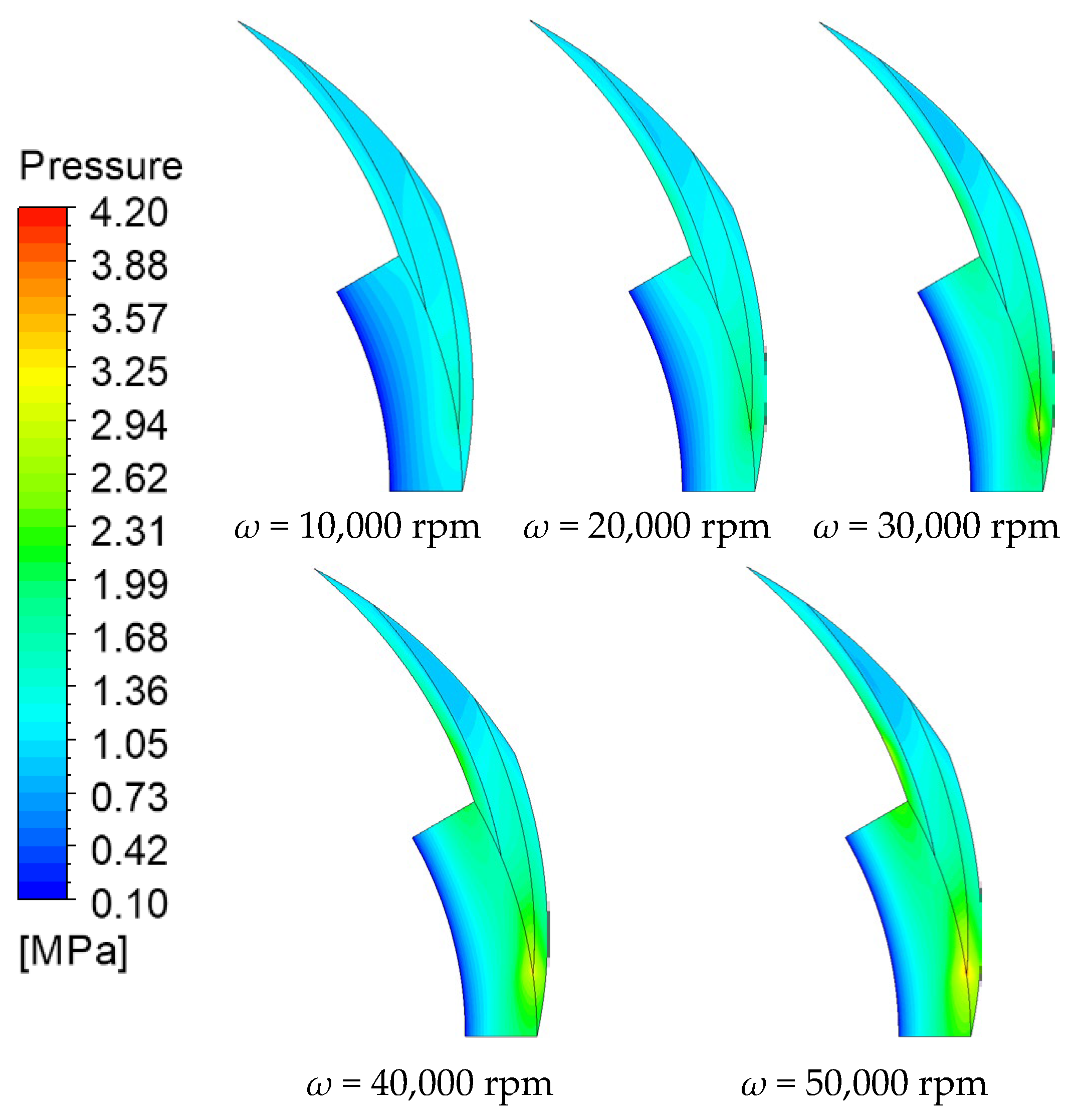
Figure A2.
The gas film pressure contours of the CS-DGS under different rotational speeds (z = 1/2 h0, pi = 1 MPa).
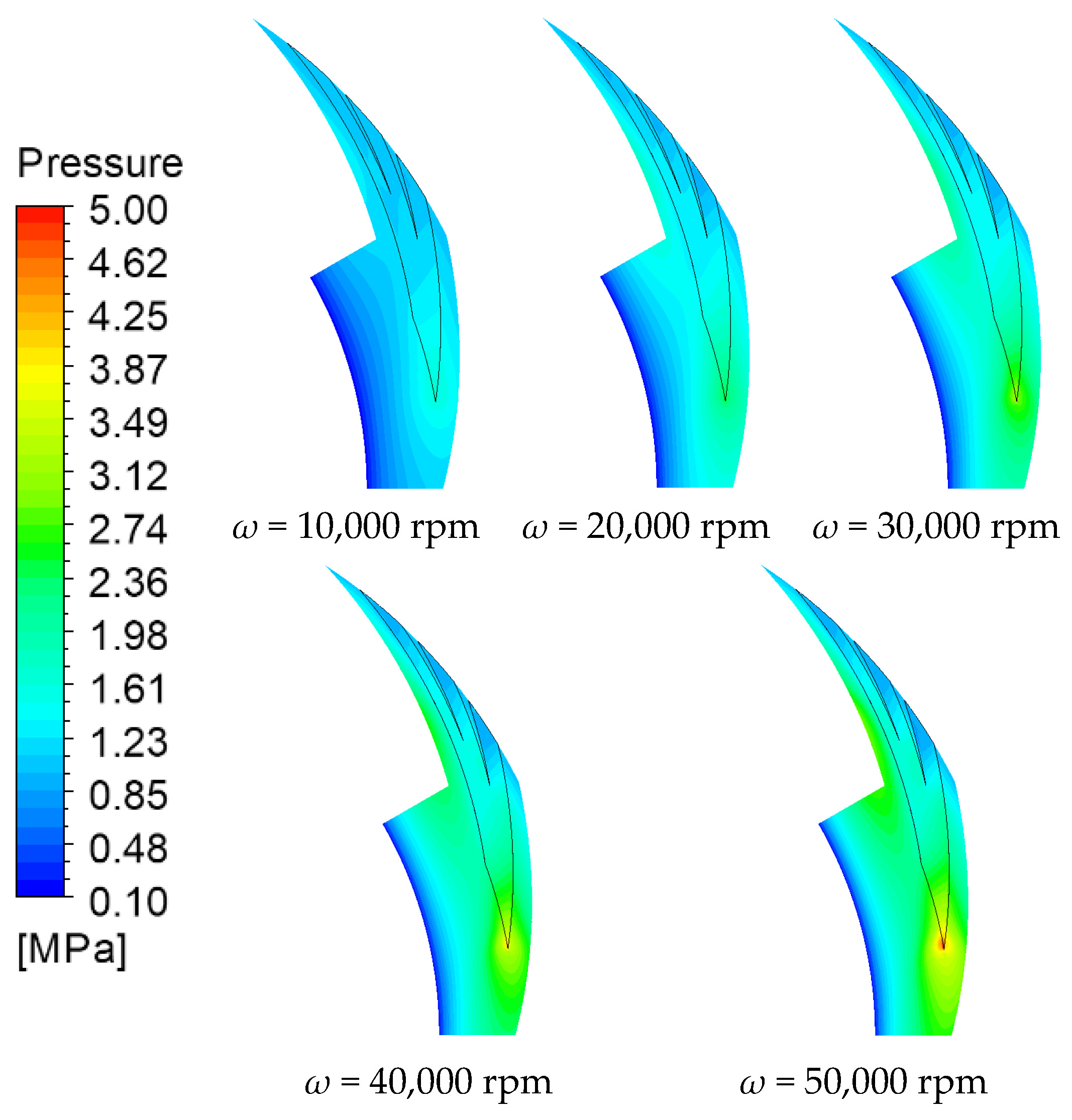
Figure A3.
The gas film pressure contours of the MC-DGS under different rotational speeds (z = 1/2 h0, pi = 1 MPa).
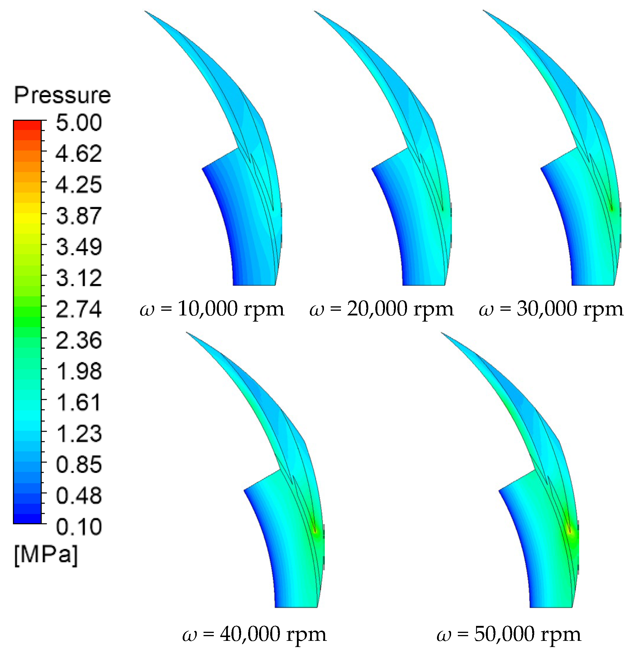
Figure A4.
The gas film pressure contours of the T-DGS under different rotational speeds (z = 1/2 h0, pi = 1 MPa).
References
- Wang, X.; Liu, M. The seal performance of compliant foil gas seal based on multi-scale analysis. Processes 2022, 10, 1123. [Google Scholar] [CrossRef] [Scilit]
- Jiang, H.; Xu, J.; Yu, S.; Wang, S.; Ding, X.; Jiang, A. Theoretical expression and screening of real gas effect of spiral groove dry gas seal. Processes 2024, 12, 1298. [Google Scholar] [CrossRef] [Scilit]
- Sun, Z.C.; An, T.; Qian, Z.L.; Xiang, F.N.; Jin, Z.Y.; Guan, A.Q.; Jin, Z.-J.; Qian, J.Y. Reliability of Valves in Nuclear Power Plant: A Review of Full Life-Cycle Frameworks and Evolution Toward Physics-Data Fusion. J. Reliab. Sci. Eng. 2026, 2, 012001. [Google Scholar] [CrossRef] [Scilit]
- Lin, Z.H.; Yu, L.J.; Hua, T.F.; Jin, Z.J.; Qian, J.Y. Seal contact performance analysis of soft seals on high-pressure hydrogen charge valves. J. Zhejiang Univ.-Sci. A 2022, 23, 247–256. [Google Scholar] [CrossRef] [Scilit]
- Espinoza-Sepulveda, N.F.; Sinha, J.K. Theoretical validation of earlier developed experimental rotor faults diagnosis model. Int. J. Hydromechatron. 2021, 4, 295–308. [Google Scholar] [CrossRef] [Scilit]
- Qin, D.; Wu, X.; Zhang, J.; Wang, X.; Yan, N. Hydraulic optimisation design of axial flow pump based on blade velocity distribution. Int. J. Hydromechatron. 2023, 6, 311–324. [Google Scholar] [CrossRef] [Scilit]
- Hong, D.H.; Kim, S.H.; Karng, S.W.; Rhee, G.H. Dynamic analysis of refueling characteristics of hydrogen refueling station. J. Mech. Sci. Technol. 2024, 38, 4911–4920. [Google Scholar] [CrossRef] [Scilit]
- Teng, L.; Jiang, J.; Peng, X.; Li, J. Influence of surface grooving methods on steady and dynamic performance of spiral groove gas face seals. Alex. Eng. J. 2023, 64, 55–80. [Google Scholar] [CrossRef] [Scilit]
- Zhang, C.; Jiang, J.; Peng, X. Numerical analysis of supercritical CO2 dry gas seals with phase transitions. Ind. Lubr. Tribol. 2022, 74, 780–787. [Google Scholar] [CrossRef] [Scilit]
- Yuan, T.; Yang, R.; Li, Z.; Li, J.; Yuan, Q.; Song, L. Thermal characteristics and cooling effect for SCO2 dry gas seal with multiple dynamic groove types. Appl. Therm. Eng. 2024, 236, 121896. [Google Scholar] [CrossRef] [Scilit]
- Yuan, T.; Li, Z.; Li, J.; Yuan, Q. Design and analysis of cooling structure for dry gas seal chamber of supercritical carbon dioxide turbine shaft end. In Turbo Expo: Power for Land, Sea, and Air; American Society of Mechanical Engineers: New York, NY, USA, 2021; Volume 85048, p. V010T30A012. [Google Scholar]
- Zhang, L.; Ding, X.; Zhang, S.; Wang, S.; Hong, X.; Bao, X. Comparative Study on Flow Characteristics and Sealing Performance of Hydrodynamic and Hydrostatic Dry Gas Seals. Lubr. Eng. 2025, 50, 16–23. [Google Scholar]
- Zhang, G.; Chen, G.; Zhao, W.; Yan, X.; Zhang, Y. An Experimental Test on a Cryogenic High-Speed Hydrodynamic Non-Contact Mechanical Seal. Tribol. Lett. 2017, 65, 80. [Google Scholar] [CrossRef] [Scilit]
- Blasiak, S.; Zahorulko, A.V. A parametric and dynamic analysis of non-contacting gas face seals with modified surfaces. Tribol. Int. 2016, 94, 126–137. [Google Scholar] [CrossRef] [Scilit]
- Bai, S.; Song, Y.; Yang, J. Elastic deformation of liquid spiral groove face seals operating at high speeds and low pressure. Int. J. Mech. Sci. 2022, 226, 107397. [Google Scholar] [CrossRef] [Scilit]
- Fairuz, Z.M.; Jahn, I.; Abdul-Rahman, R. The effect of convection area on the deformation of dry gas seal operating with supercritical CO2. Tribol. Int. 2019, 137, 349–365. [Google Scholar] [CrossRef] [Scilit]
- BŁAsiak, S.; Jakub, T. Analysis of Pressure Distribution in Non-Contacting Impulse Gas Face Seals. In Terotechnology XII; Materials Research Forum LLC.: Millersville, PA, USA, 2022. [Google Scholar]
- Luo, J.; Brillert, D. Experimental Investigations on the Pressure Fluctuations in the Sealing Gap of Dry Gas Seals With Embedded Pressure Sensors. J. Eng. Gas Turbines Power 2021, 143, 031005. [Google Scholar] [CrossRef] [Scilit]
- Yang, J.; Ji, X.; Chen, J.; Bai, S. Heat dissipation and energy transfer performance of helium face seal with spiral grooves at cryogenic condition. Appl. Therm. Eng. 2023, 227, 120385. [Google Scholar] [CrossRef] [Scilit]
- Hu, F.; He, Q.; Huang, W.; Yin, Y.; Wen, X.; Liu, Y.; Wang, Y. Face grooves for state monitoring in dry gas seals. Tribol. Int. 2023, 189, 108950. [Google Scholar] [CrossRef] [Scilit]
- Zhang, W.; Xu, L.; Sun, Y.; Ren, Y.; Ding, X. The influence of different structural parameters on lift off speed of spring groove gas seal. J. Braz. Soc. Mech. Sci. Eng. 2023, 45, 491. [Google Scholar] [CrossRef] [Scilit]
- Zirkelback, N. Parametric Study of Spiral Groove Gas Face Seals. Tribol. Trans. 2000, 43, 337–343. [Google Scholar] [CrossRef] [Scilit]
- Sun, X.; Song, P.; Mao, W.; Deng, Q.; Xu, H.; Chen, W. Analysis of Dynamic Contact Characteristics of Dry Gas Seal During Start-Up and Stop Considering Seal Ring Material Properties and Surface Morphology. CIESC J. 2021, 72, 4279–4291. [Google Scholar]
- Wang, E.; Liu, D.; Wang, S. Texture optimizing method for rotating shaft with lip seal considering processing errors. Chin. J. Mech. Eng. 2025; In Press. p. 100199. [CrossRef] [Scilit]
- Gabriel, R.P. Fundamentals of spiral groove noncontacting face seals. Lubr. Eng. 1994, 50, 215–224. [Google Scholar]
- Chen, Y.; Zhuo, Z.; Li, Y.; Li, X.; Wang, B.; Jin, J.; Zhang, C. Prediction of spiral groove dry gas seal performance and intelligent optimization of structural parameters. Tribol. Int. 2024, 193, 109439. [Google Scholar] [CrossRef] [Scilit]
- Kou, G.; Li, X.; Wang, Y.; Lin, M.; Tan, C.; Mou, M. Steady performance and dynamic characteristics of a superellipse groove dry gas seal at a high-speed condition. Ind. Lubr. Tribol. 2020, 72, 789–796. [Google Scholar] [CrossRef] [Scilit]
- Bai, S.; Chu, D.; Ma, C.; Yang, J.; Bao, S. Thermo-Hydrodynamic Effect of Gas Split Floating Ring Seal with Rayleigh Step Grooves. Materials 2023, 16, 2283. [Google Scholar] [CrossRef] [Scilit]
- Jiang, J.; Peng, X.; Li, J.; Chen, Y. A comparative study on the performance of typical types of bionic groove dry gas seal based on bird wing. J. Bionic Eng. 2016, 13, 324–334. [Google Scholar] [CrossRef] [Scilit]
- Chen, Y.; Jiang, J.; Peng, X. Dynamic characteristics and transient sealing performance analysis of hyperelliptic curve groove dry gas seals. Tribol. Int. 2017, 116, 217–228. [Google Scholar] [CrossRef] [Scilit]
- Zhang, C.; Jiang, J.; Zhao, W.; Jin, J.; Peng, X. A comprehensive multi-objective, multi-parameter and multi-condition optimization of a spiral groove in dry gas seals. J. Braz. Soc. Mech. Sci. Eng. 2022, 44, 206. [Google Scholar] [CrossRef] [Scilit]
- Xia, X.; Xiao, Y.; Zhang, M.; Jiang, J.; Li, C. The effect of surface profile and groove bottom profile on steady-state performance of dry gas seals. Ind. Lubr. Tribol. 2024, 77, 105–114. [Google Scholar] [CrossRef] [Scilit]
- Yan, R.; Chen, H.; Zhang, W.; Hong, X.; Bao, X.; Ding, X. Calculation and verification of flow field in supercritical carbon dioxide dry gas seal based on turbulent adiabatic flow model. Tribol. Int. 2022, 165, 107275. [Google Scholar] [CrossRef] [Scilit]
- Jiang, J.; Peng, X.; Zong, C.; Zhao, W.; Chen, Y.; Li, J. Enhancing Film Stiffness of Spiral Groove Dry Gas Seal via Shape Modification at Low Speed: Numerical Results and Experiment. Tribol. Trans. 2019, 62, 931–942. [Google Scholar] [CrossRef] [Scilit]
- Du, Q.; Gao, K.; Zhang, D.; Xie, Y. Effects of grooved ring rotation and working fluid on the performance of dry gas seal. Int. J. Heat Mass Transf. 2018, 126, 1323–1332. [Google Scholar] [CrossRef] [Scilit]
- Lu, J. Theoretical analysis and experiment on gas film stiffness with slip flow in a spiral-grooved dry gas seal. Ind. Lubr. Tribol. 2021, 73, 1226–1236. [Google Scholar] [CrossRef] [Scilit]
- Song, Y.; Bai, S.; Yang, J.; Chen, J. Fluid Cavitation Intensity in Zero Leakage Upstream Pumping Face Seals with Spiral Grooves. Int. J. Appl. Mech. 2023, 15, 2350095. [Google Scholar] [CrossRef] [Scilit]
- Wang, Y.; He, Y.; Xie, X.; Huang, Z.; Xu, H.; Hu, Q.; Ma, C. Design and Simulation of a New Near Zero-Wear Non-Contact Self-Impact Seal Based on the Tesla Valve Structure. Lubricants 2023, 11, 102. [Google Scholar] [CrossRef] [Scilit]
- Fairuz, Z.M.; Jahn, I. The influence of real gas effects on the performance of supercritical CO2 dry gas seals. Tribol. Int. 2016, 102, 333–347. [Google Scholar] [CrossRef] [Scilit]
- Zhang, L.; Ding, X.; Wang, S.; Zhang, S.; Ding, J. Research progress on the dynamic stability of dry gas seals. Processes 2024, 12, 575. [Google Scholar] [CrossRef] [Scilit]

Disclaimer/Publisher’s Note: The statements, opinions and data contained in all publications are solely those of the individual author(s) and contributor(s) and not of MDPI and/or the editor(s). MDPI and/or the editor(s) disclaim responsibility for any injury to people or property resulting from any ideas, methods, instructions or products referred to in the content. |
© 2026 by the authors. Licensee MDPI, Basel, Switzerland. This article is an open access article distributed under the terms and conditions of the Creative Commons Attribution (CC BY) license.