


Abstract
Background: Modular and autonomous rail-based transport concepts promise increased flexibility and efficiency, but their feasibility strongly depends on reliable and scalable terminal handling operations. In such systems, transport units must be safely and rapidly coupled to carrier units without manual intervention. Methods: This study presents a structured pod-handling concept for a modular rail transport system, covering transport unit preparation, crane-based lifting and positioning, mechanical coupling via twist-lock interfaces, and automated electrical and media connections. To evaluate operational performance, a discrete-event simulation model was developed in AnyLogic that represents the complete loading process from order reception to pod dispatch. Results: Simulation results show that a single crane is sufficient under low-demand conditions, maintaining an average processing time of approximately 12 min per order. As demand increases, system performance becomes highly sensitive to crane availability; insufficient resources lead to excessive waiting times. For high-frequency demand, scalable crane allocation is required to preserve stable throughput. Conclusions: The results confirm that automated pod-handling mechanisms, combined with demand-adaptive terminal resources, are essential for the viability of modular rail pod systems. The proposed process model and simulation framework guide terminal design and support the integration of decentralised rail pods into future multimodal mobility and logistics networks.
1. Introduction
Recent developments in rail transport focus on increasing flexibility, automation, and interoperability through modular and autonomous transport concepts [1,2]. These approaches aim to enable seamless door-to-door mobility [3] by separating propulsion units from transport modules and integrating them into digitalised, decentralised service platforms [4,5]. Such systems are designed to operate across multiple transport modes, forming multimodal interfaces that support both passenger and freight mobility within Mobility as a Service (MaaS) and logistics ecosystems [6,7].
Recent research increasingly focuses on the automation and digitalization of rail freight logistics, particularly in relation to terminal operations and modular transport concepts. Several studies have investigated automated loading and unloading processes and scheduling optimisation in intermodal terminals, demonstrating the importance of coordinated crane and handling equipment operations for improving system throughput and reducing waiting times [8,9]. In parallel, system-level analyses highlight the growing role of automation components in rail freight networks and their influence on operational efficiency and service design [10]. At the technological level, recent initiatives such as digital automatic coupling and intelligent freight wagon concepts illustrate the broader transition toward automated and digitally integrated rail freight systems [11,12]. Moreover, studies on autonomous train operations emphasise the potential of advanced automation technologies to improve the competitiveness and flexibility of rail freight transport [13]. These developments are complemented by research on automated intermodal transport systems and simulation-based evaluation of new rail logistics architectures, which provide methodological foundations for analysing innovative freight handling concepts [14]. The present study builds on these research directions and contributes by evaluating the operational performance of an automated pod-handling concept designed for modular rail freight systems.
The main element of the developed solution is the pod system. The pod system can be defined as a decentralised, autonomous, rail-based intermodal transport concept that separates the carrier unit (CU, an autonomous vehicle providing propulsion, energy storage, and control systems) from the transport unit (TU, a container for passengers or freight), allowing seamless transfers across modes such as rail, road, or cable cars/funicular without reloading or changing vehicles [15]. It enables on-demand, door-to-door services with constant availability [16,17].
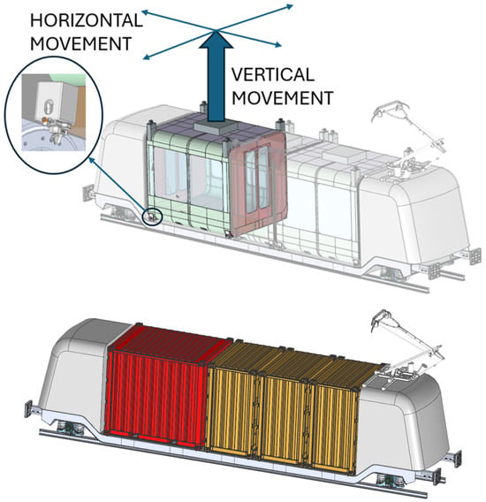
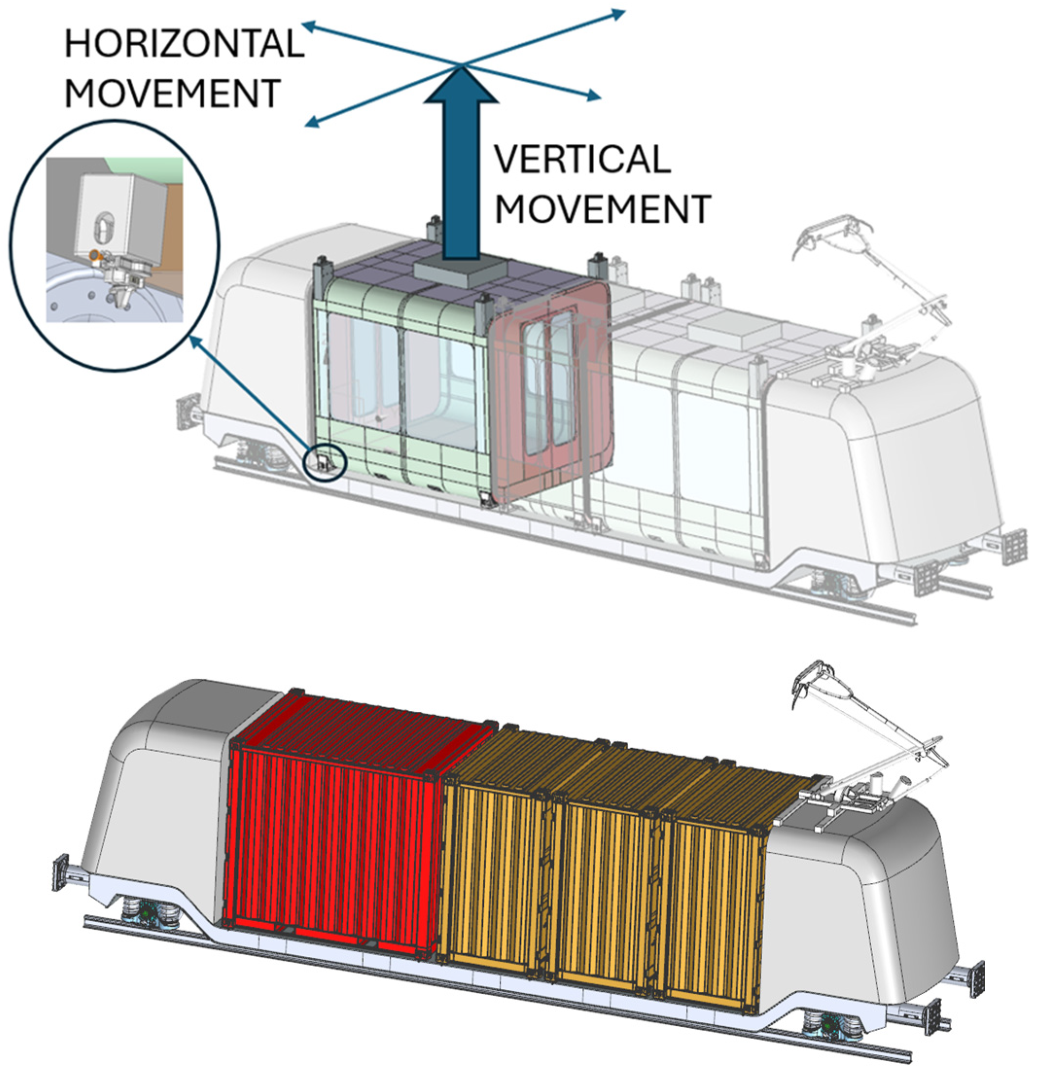
Pods are small electric vehicles consisting of the CU and the TU, connected by a coupling system and designed to transport a few to several passengers. They are typically constructed from lightweight, durable materials to maximise energy efficiency and safety [18]. The design of these TUs can vary based on capacity and intended use, but they generally focus on providing a smooth, reliable ride. These TUs can be easily replaced with cargo because they are compatible with ISO containers. The system is shown in Figure 1.
Figure 1.
The pod (TU and CU) in passenger (upper) and cargo (lower) configuration. A system of manipulation is shown.
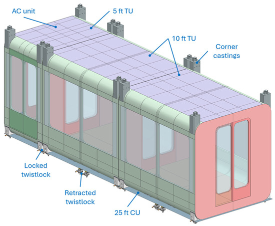
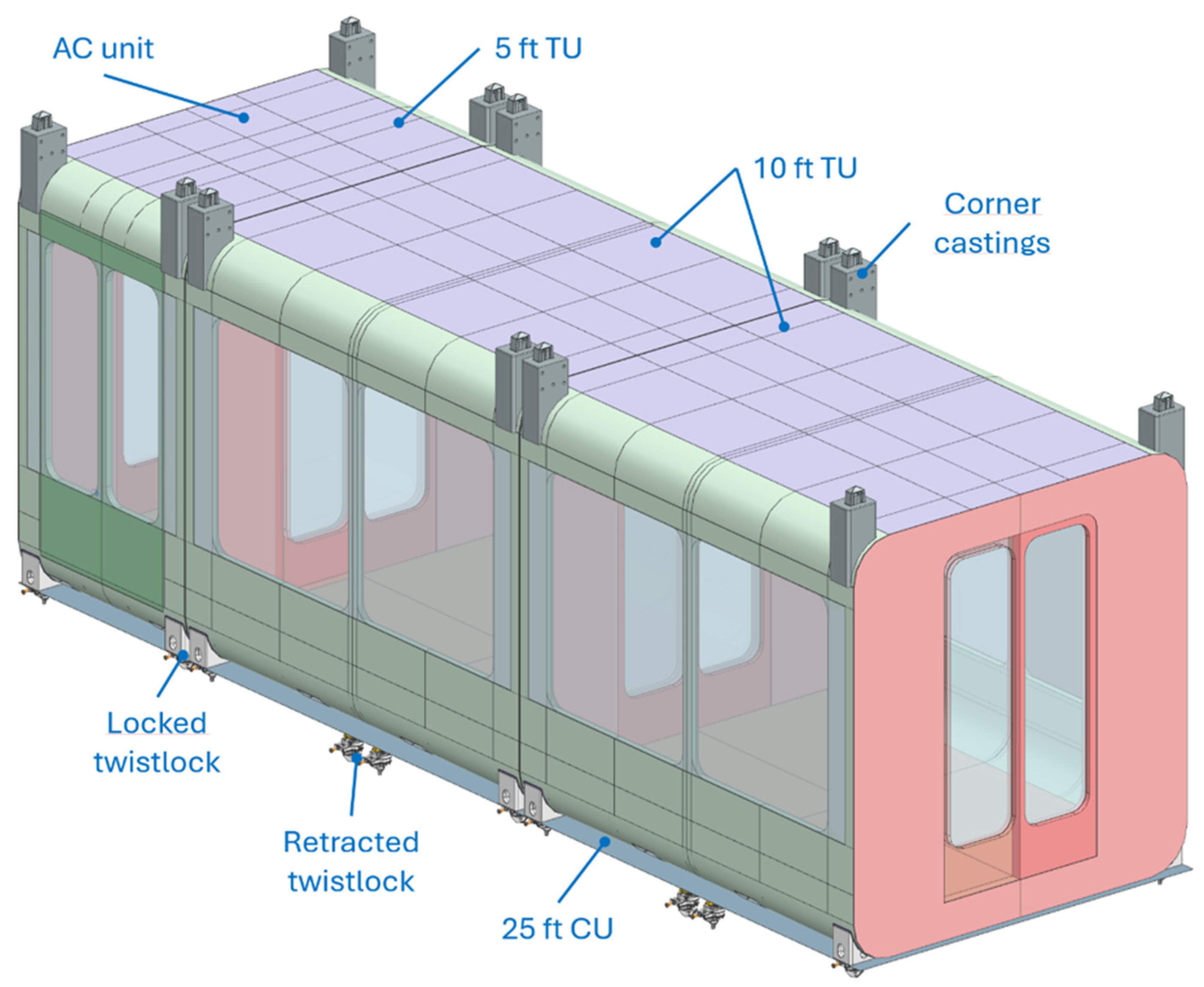
The transport unit (TU) designed for passenger transport is illustrated in Figure 2. The TU represents a modular cabin concept intended to be transported autonomously within the modular rail/road transport system. Its structure is based on a lightweight rigid frame, typically manufactured from high-strength steel or aluminium alloys in order to ensure sufficient structural integrity while minimising overall mass [19,20]. The external panels may be composed of composite materials or lightweight sandwich panels that provide thermal insulation and durability against environmental conditions. The modular architecture allows the TU to be produced in several standardised lengths, such as 5 ft or 10 ft configurations, depending on operational requirements and passenger capacity [21].
Figure 2.
The pod (TUs of different capacities).
The interior space is designed to provide a comfortable and safe passenger environment and can be configured with seating, standing areas, or accessibility features depending on the intended service. Large side openings or entrance modules can be integrated to facilitate fast passenger boarding and disembarking. The TU also incorporates mounting interfaces that allow secure connection with the carrier unit during transport and enable automated handling during loading and unloading operations [22,23]. In addition, the design may integrate electrical systems for lighting, ventilation, and communication, ensuring passenger comfort during operation.
Conventional rail container transport typically relies on large intermodal terminals equipped with heavy handling equipment such as gantry cranes and reach stackers [24]. These operations require significant infrastructure and may lead to operational delays due to complex coordination between transport vehicles and terminal equipment [25].
The proposed modular transport concept aims to simplify these operations by introducing standardised transport units that can be automatically handled within the terminal environment [26]. The separation of transport units and carrier vehicles enables more flexible loading and unloading processes and may reduce terminal dwell times compared with conventional container handling systems [27,28].
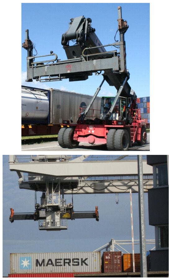
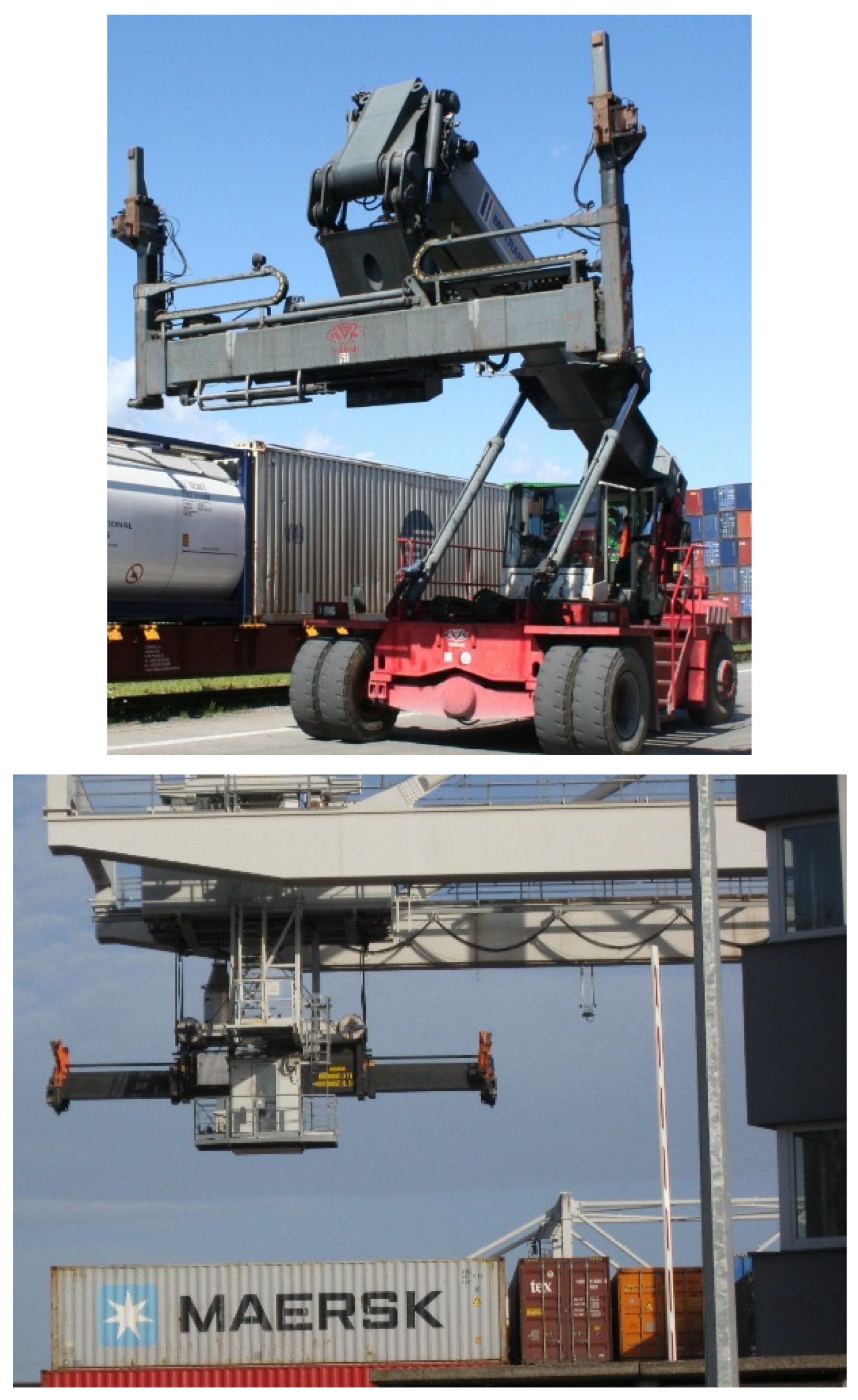
Such an approach could improve the operational efficiency of rail freight transport, particularly in decentralised logistics systems where smaller and more flexible terminals are required. The logistical aspects of modular pod systems require well-defined handling concepts to enable the safe and efficient transfer of TUs between storage areas and carrier vehicles [29]. These concepts must address handling, storage, loading, and unloading operations, as well as the mechanical, electrical, and media interfaces between TUs and CUs [30,31]. The pod-handling connection mechanism defines how a TU is moved from its storage location to the loading area and subsequently integrated with the CU using crane-based operations and auxiliary handling systems in a standardised manner. Two principles [32] of handling (by reach stacker and by crane) are shown in Figure 3.
Figure 3.
Handling principles (reach stacker—(upper) and crane—(bottom)).
To support the conceptual design, a discrete-event simulation model was implemented in AnyLogic. Process durations are defined using realistic values derived from comparable terminal handling operations. The combined use of conceptual design and simulation provides insight into the operational behaviour of the handling mechanism under realistic conditions [33,34]. This approach facilitates the identification of potential bottlenecks and supports the development of automated handling systems [35,36].
2. Materials and Methods-Description of Pod-Handling Procedures
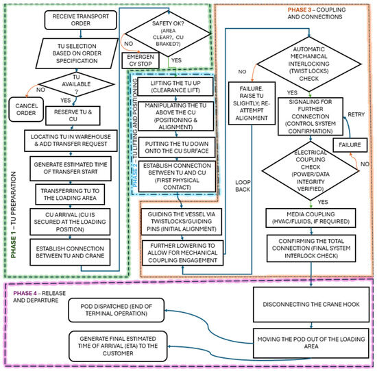
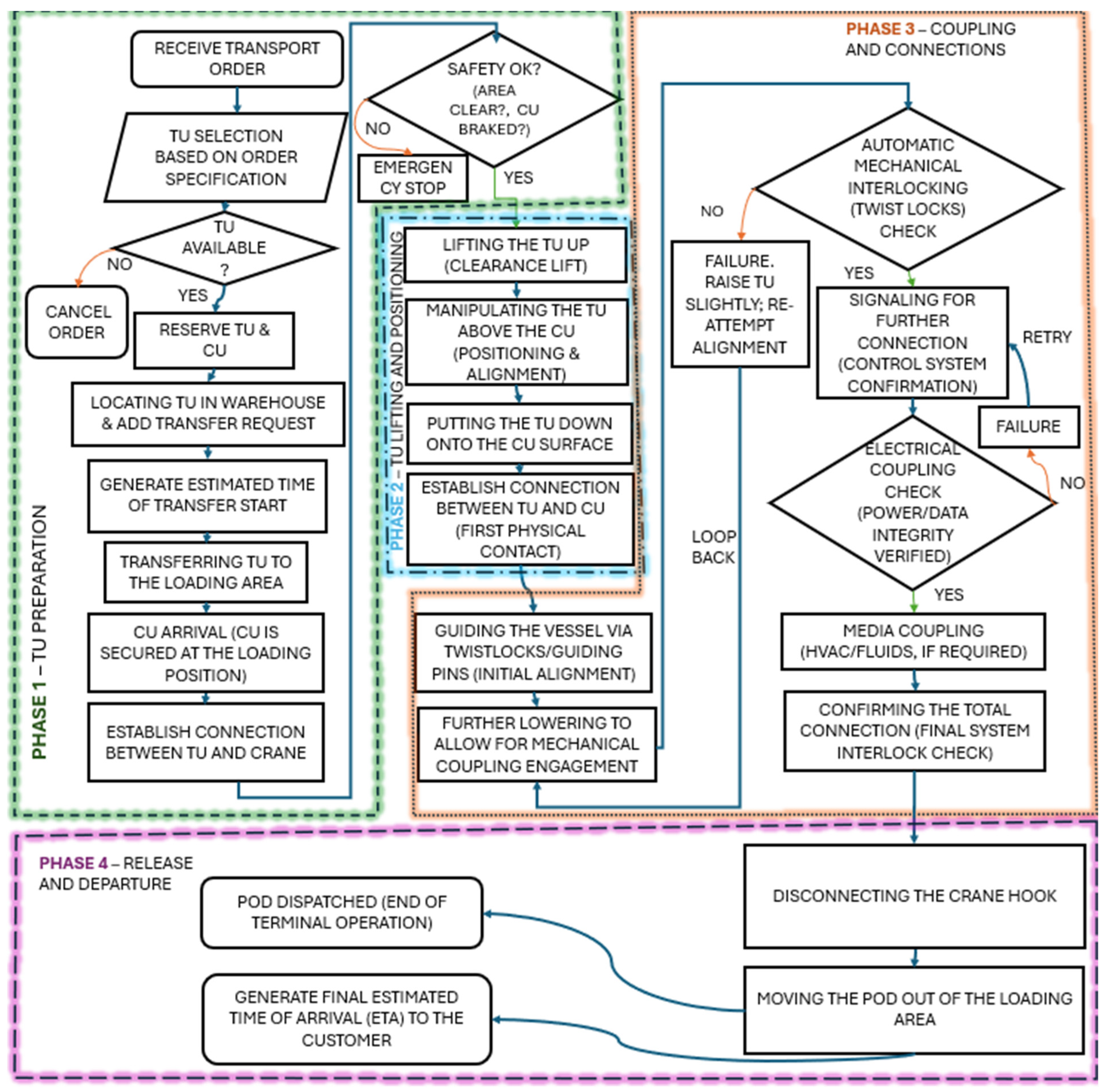
The handling operation between TU and CU has sequential procedures designed to ensure safety and efficiency. The digital control architecture of the terminal consists of two main systems: the Warehouse Management System (WMS) and the Terminal Control System (TCS). The WMS operates at the logistics planning level and is responsible for order processing, allocation of transport units, storage management, and scheduling of internal transport operations. The TCS operates at the operational level and supervises real-time control of cranes, carrier units, and safety systems within the terminal environment. Communication between both systems is realised through a digital interface that exchanges operational commands and status information. The process consists of twenty steps grouped into four operational phases, as shown in Figure 4.
Figure 4.
Flow chart representation.
It should be noted that the following handling procedure represents a conceptual and partially idealised operational framework intended to define the sequence of automated processes. Certain steps reflect anticipated technological capabilities and therefore require further validation under real operational conditions.
Handling phases are TU preparation and transfer; TU lifting and positioning; coupling and connections; release and departure. Each phase includes both physical operations and digital checks executed by the Terminal Control System (TCS).
The process starts with receiving the order from the customers. To assign a pod for transport, the pod’s capacity is determined, and orders from enough passengers or enough freight for the same pod to the same or similar destination should be received. A more detailed description of each step follows.
2.1. Phase 1: TU Preparation and Transfer
- Step 1. Selection of the TU based on the customers’ demands
The transportation process begins with receiving customer orders. The Warehouse Management System receives the order by determining the correct specifications and availability of the TU: correct size and type (passenger or freight), destination, time, cleanliness, and maintenance status. As TU is selected, the compatible CU is assigned to it, and the order is confirmed.
- Step 2. Locating the TU in the warehouse, adding the transfer request to the queue
The Warehouse Management System (WMS) identifies the exact location of the reserved TU, typically using RFID/GPS tracking, and manages the internal warehouse operations for its recovery and movement. It assigns the picking and transferring task to either an available automated guided vehicle (AGV) or a human-operated forklift. The real-time logistics queue is scheduled for the order’s transfer to the loading bay. The WMS determines the Estimated Time of Transfer Start (ETTS).
- Step 3. Transferring the TU via forklift (or other means) to the loading area
The assigned vehicle (AGV or human-operated forklift/straddle) retrieves the selected and reserved TU from its storage location and transports it along the predefined, controlled route to the designated loading area, where the TU will be loaded onto the CU. The TU is placed precisely within the staging area, becoming ready for the crane (or other loading device) to lift and load it.
- Step 4. CU Docking and Loading Crane System (LCS) Readiness
To prepare the final loading area, the assigned CU is autonomously moved to the loading bay, precisely aligned to the docking position using onboard cameras/Lidar for high accuracy, and the CU’s safety brakes are applied and locked. The loading crane system is positioned correctly for lifting and loading the TU. The docking process is supervised by the Terminal Control System (TCS), which continuously evaluates the vehicle trajectory using sensor fusion from LiDAR, cameras, and proximity sensors installed in the terminal infrastructure. A runtime collision-avoidance module compares predicted vehicle trajectories with detected obstacles and dynamically adjusts the vehicle path or triggers an emergency stop if necessary. This approach follows established principles used in autonomous vehicle safety systems, where real-time monitoring ensures safe navigation within confined operational environments.
- Step 5. Establishing a connection between the TU and the crane hook
To establish a safe connection between the TU and the crane using standardised and safety-compliant methods, the crane’s spreader or hook mechanism slowly lowers towards the TU’s standardised lifting points. The vision system (cameras) and proximity sensors guide the automatic engagement between the hook/spreader and TU’s fittings (twist lock pins). The sensors on the hook/spreader confirm that the connections are fully secured and locked, preventing the TU from falling or dropping when lifted.
- Step 6. Safety assessment, i.e., ensuring the loading area is unoccupied, and the carrier is braked to prevent accidents
To ensure the complete and immediate safety of personnel and equipment before overhead lifting, the loading crane system and stationary sensors around the loading bay conduct a real-time scan of the entire loading bay for any human or foreign objects. The system verifies brake lock confirmation from CU. The system will not allow lifting to begin until both conditions (no occupancy and CU brakes locked) are confirmed.
2.2. Phase 2: TU Lifting and Positioning
- Step 7. Lifting the TU up
The LCS hoist motor lifts the TU vertically, slowly, and smoothly. It continuously monitors the load weight via the load sensors and compares it against the expected weight and maximum capacity. The system monitors sudden spikes in resistance or excessive tilt, indicating the TU is snagged (stuck) on the ground or surrounding structure.
- Step 8. Manipulating the TU above the CU
The TU is moved horizontally and brought over the CU. The system continuously monitors the position of the TU relative to the CU’s central docking target using onboard sensors (e.g., laser range fingers). The LCS uses sophisticated drive controls (e.g., anti-sway algorithms) to minimise the pendulum effect of the suspended load. Now the TU is suspended, precisely centred directly above the CU coupling interface, and ready to be lowered.
- Step 9. Putting the TU down
To perform the first controlled descent and establish physical contact between the TU and the CU’s chassis, the LCS begins a slow, controlled vertical descent towards the CU. CU on board proximity sensors (ultrasonic/optical) track the distance to the TU’s underside. The descent rate is slowed further, and sensors on the CU confirm the initial “soft contact” when the TU’s guiding structures touch the CU frame.
- Step 10. Establishing a connection between the TU and the CU
Slight positional adjustment is made by the CU’s onboard micro-actuators (e.g., in the suspension or chassis) based on sensor feedback. A closed-loop feedback signal is provided to the CU’s coupling control system by the alignment sensors on both TU and CU. Then the system confirms that the alignment is within the tolerance limit required for the guiding elements to function. During this step, the initial positional alignment is achieved, and the TU is ready to be seated by mechanical guides. In practical implementations, this fine positioning may be realised either by onboard micro-actuators or by high-precision crane control systems. However, such solutions must address challenges related to vibration, positioning accuracy, robustness, and cost efficiency, and therefore require further engineering validation.
2.3. Phase 3: Coupling and Connections
- Step 11. Guiding the vessel via twist locks (first contact point)
To physically draw the TU into the exact, final seating position, the LCS continues lowering the TU gently. Conical/Funnel-shaped guides on the CU receive the corresponding pins from the TU, forcing any remaining slight misalignment to be corrected as the TU settles. The TU is now physically and fully resting on the exact lateral and longitudinal position of the CU frame.
- Step 12. Further lowering to allow for mechanical coupling
This last vertical movement confirms that the interfaces are compressed/aligned properly for lockup. It eliminates any remaining vertical space and confirms the coupling interfaces (for mechanical, electrical, and media connections) are in their correct home position and ready for locking and engagement. To realise this, the LCS lowers the TU for the last few millimetres, compressing any vertical seals or dampening pads. The TU’s load is fully transferred from the LCS hook onto the CU’s chassis. This time, the LCS load cells (sensors) show almost no load, ensuring that the CU fully supports the TU, and then the LCS completely releases the TU.
- Step 13. Automatic interlocking of twist locks
This is an automated mechanical securing of the TU to the CU chassis. The CU’s automated, motorised twist-lock (or similar devices) are tilted and rotated into the locking position. A redundant sensor system (e.g., a torque sensor and a proximity sensor at the final position) verifies that all locks are fully engaged, locked, and under the correct tension. This means TU and CU are firmly connected and can function as a single unit (vehicle), able to safely operate at higher speeds and withstand dynamic forces such as acceleration, braking, and cornering forces. The CU system sets a flag that confirms the mechanical coupling is secure.
- Step 14. Signalling for further connection
The mechanically coupled units inform the system that they are ready for electrical and media connection.
The CU’s coupling control system sends “the mechanical lock confirmed” signal to the TU control unit and the TCS. The TU’s control unit acknowledges the signal. And the TCS double-checks the mechanical lock status with the CU’s power and media control status, ensuring the systems are ready for power and fluid connections.
- Step 15. Electrical coupling
The connection of the high-voltage power source and critical control data lines. This is to establish the connection between the TU’s onboard subsystem, such as lighting, HVAC, and sensors, and the CU’s high-voltage power source (supply) and operational data network. To do this, the CU extends the automated electrical connector blocks into the receiving port in the TU. The connectors are pushed together and locked mechanically or magnetically. And the CU performs a rapid, low-power continuity test and a high-speed data link check to verify power quality and communication integrity.
- Step 16. Media coupling
The connection of non-electrical service lines, such as HVAC (heating, ventilation, air conditioning), water, and waste. The necessity of media connections depends on the specific application scenario. While such connections may be relevant for passenger transport units (e.g., HVAC, water supply, or waste systems), their application in freight transport is limited and may be omitted in simplified configurations. Consequently, this step should be considered optional and dependent on the operational requirements and type of transport unit. The energy demand associated with these auxiliary systems is relatively small compared with the traction energy required for vehicle movement. Preliminary estimations indicate that these auxiliary loads represent less than approximately 5% of the total carrier unit battery capacity and therefore do not significantly affect operational feasibility during the loading process. To achieve this, the CU extends and links the automated media coupling and performs an immediate, short-duration pressure/vacuum test on the media lines to detect leaks at the seal interface. The coupling is locked, and the test result is logged, confirming there are no leaks.
- Step 17. Confirming the connection
The final system-wide confirmation procedures are conducted before authorising the unit for movement. The CU’s onboard system generates the final report (including results from steps 13, 15, and 16). The CU transmits the report to TCS and requests “operational clearance”. The TCS reviews the report against the safety threshold and issues the “ready to move” authorisation.
2.4. Phase 4: Release and Departure
- Step 18. Disconnecting the crane hook
The loading crane system receives the signal to disconnect the hook/spreader locks from the TU and releases them. Sensors on the hook verify that the locks are completely disconnected and retracted. The loading crane system pulls up the hook/spreader to its maximum retracted height and repositions the gantry clear of the track. This time, the LCS is totally clear of the pod’s movement area, and the loading bay status is “available”.
- Step 19. Moving the pod out of the loading area to allow the loading of another TU
The CU releases its safety brakes. The pod (TU and CU) starts the slow, controlled autonomous movement out of the loading bay toward the dispatching track. Sensors verify that the pod has passed the predefined clearance point. The WMS updates the loading bay status to “available”.
- Step 20. The pod is on its way to the customer (output: estimated time of arrival)
The pod enters a terminal traffic coordination zone where its movement is synchronised with other autonomous vehicles operating in the terminal environment. The Terminal Control System communicates with the central rail traffic management system to allocate a departure slot and route segment. In dense terminal environments, this coordination may involve intersection management algorithms or platoon-based scheduling strategies that regulate vehicle priority and prevent traffic conflicts. The traffic control system allocates the pod’s final route and time slot within the network. The WMS calculates a dynamic, traffic-adjusted estimated time of arrival (ETA) based on real-time network conditions and sends it to the customer. Now, the pod joins the main traffic network, and operations are handed over to the central traffic control system.
3. Simulation Model with AnyLogic
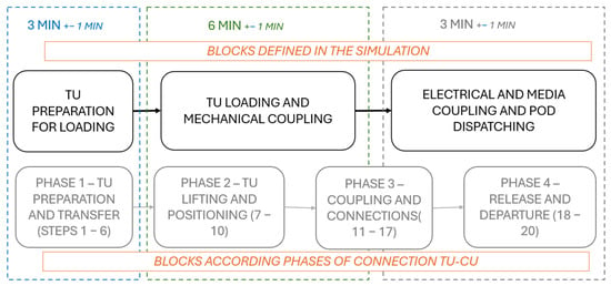
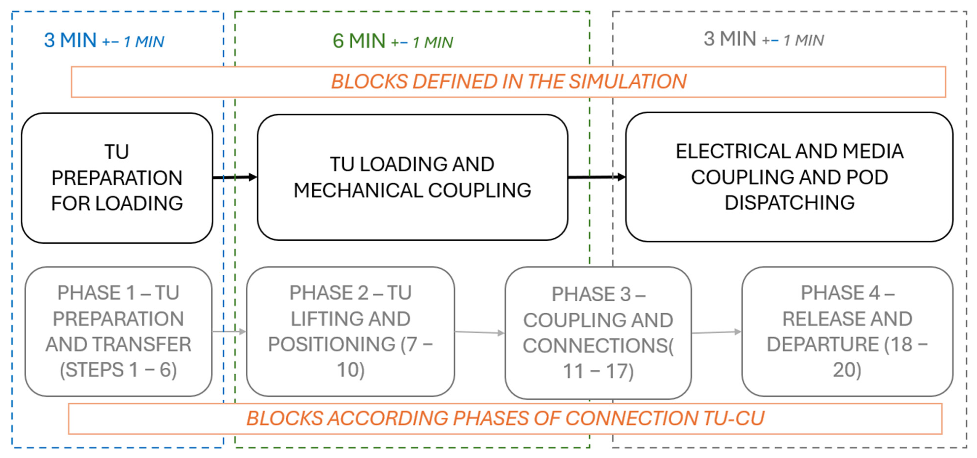
This AnyLogic (SW version 8.9.6) discrete-event simulation model simulates the pod-loading process for the system. The simulation demonstrates how the TUs are processed, from order receipt by the Warehouse Management System through loading onto the CU to final dispatch. The purpose is to analyse the loading process’s efficiency, identify bottlenecks, and measure performance metrics in a risk-free digital environment. The most important input parameters of the simulation model are the processing times of individual handling operations, which determine the throughput capacity and waiting time behaviour of the terminal system. It can be described according to Figure 5.
Figure 5.
Time consumption for each phase.
In the initial conceptual model, these processing times were represented using deterministic values. The processing times used in the simulation model were derived from operational data reported for automated container terminals and intermodal transshipment systems in [37,38,39]. In the revised model, stochastic variability was introduced in order to better reflect real terminal operations. Preparation time was modelled using a triangular distribution (2, 3, 4 min), loading and mechanical coupling were modelled using a triangular distribution (5, 6, 7 min), and auxiliary connections were modelled using a triangular distribution (2, 3, 4 min). These distributions represent minor operational delays caused by positioning adjustments, sensor calibration procedures, or mechanical alignment corrections during automated coupling. This approach reflects the limited availability of empirical data while allowing realistic variability in terminal operations.
To ensure statistical robustness of the results, each simulation scenario was evaluated using 30 independent replications with different random seeds. The standard deviations and 95% confidence intervals were calculated for key metrics, including total processing time and waiting time. This approach reduces the influence of stochastic variability and improves the reliability of the simulation outcomes.
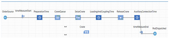
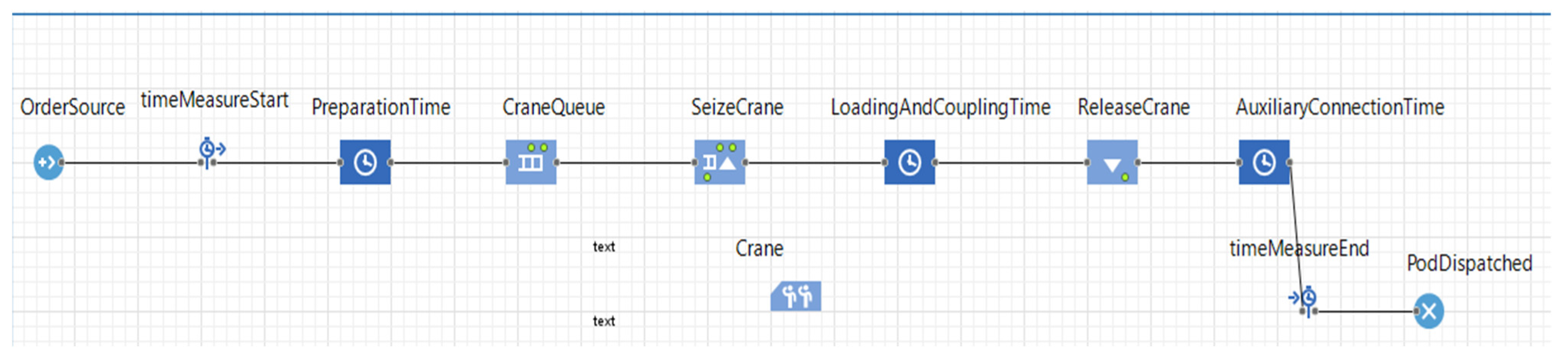
The simulation model in the AnyLogic software is shown in the following Figure 6.
Figure 6.
Simulation model in AnyLogic SW.
The simulation follows this simplified workflow [40,41]:
Order Generation → Preparation → Queue for Crane → Loading and Mechanical Coupling → Auxiliary Connections → Dispatch.
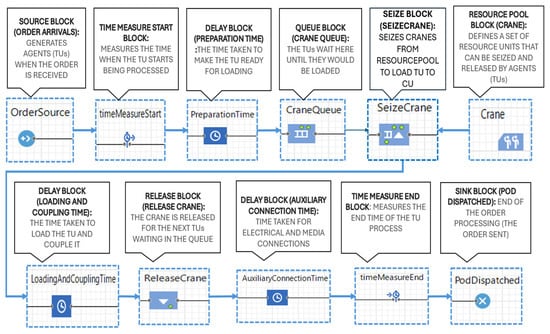
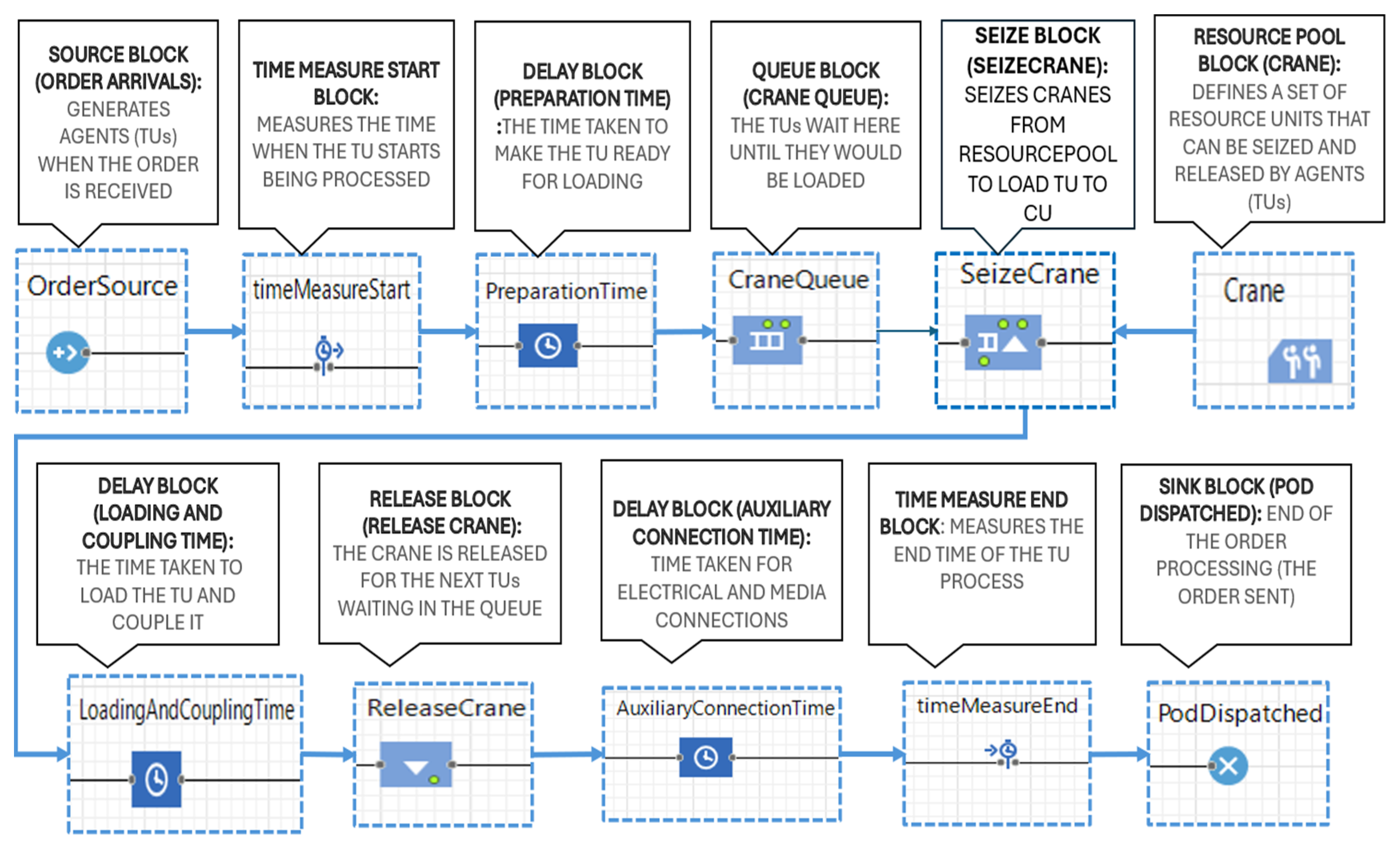
The process from the AnyLogic SW is shown in more detail in Figure 7.
Figure 7.
AnyLogic model of the pod loading process.
The main blocks involved in the model can be defined as follows:
Source block (Order Source). This is the common starting point for the process, and it generates agents. In our case, it generates new transport orders whenever an order is received.
Time Measure Start block. This block remembers the time when an agent passes through it. Later, when the agent passes through one of the corresponding Time Measure End blocks, the time the agent spent between these two “marker” blocks is measured.
Time Measure End block. For each incoming agent, this block measures the time it has spent since passing through one of the corresponding Time Measure Start blocks. Time Measure End and Time Measure Start form a pair of blocks that measure the time that agents spend between them (given points in a flowchart), such as “time in system”, “length of stay”, and so on.
Delay block. The Delay block delays agents for a given amount of time.
Preparation Time. The time needed to prepare the TU for loading. It includes the time required to move the TU from its location to the loading area, where it can be lifted and loaded onto the CU.
Loading And Coupling Time. This is the time needed to lift and load the TU onto the CU using the crane and mechanically couple it with the CU.
Auxiliary Connection Time. Time for final connections (electrical and media coupling) and administrative tasks, including disconnecting the crane hook.
Queue block (Crane Queue). The Queue block models a queue (a buffer) of agents waiting to be accepted by the following block(s) (Seize Crane block) in the process flow, or a general-purpose storage for the agents. In our case, the TUs wait here until they get the free crane to be loaded.
Seize block (Seize Crane). The Seize block captures a given number of resource units from a given Resource Pool block. In our model, seize block captures (takes) the available number of cranes from the resource pool (named crane).
Resource Pool block (Crane). The Resource Pool block defines a set of resource units that agents can seize and release using the Seize and Release blocks. Cranes were used as the resource (operating device) to load the TU onto the CU in the simulation model.
Release block (Release Crane). The Release block releases a specified number of resource units that were previously seized by the Seize block.
Crane allocation in the simulation model follows a first-come, first-served (FCFS) scheduling policy, where transport units are processed in the order of arrival to the crane queue. When multiple cranes are available, the first idle crane is assigned to the next waiting unit. No priority-based dispatching rules were considered in the current model. For modelling purposes, cranes are assumed to operate in parallel without mutual interference, representing an idealised terminal configuration with spatially separated operating zones. Collision avoidance, trajectory planning, and detailed crane coordination are assumed to be managed by the Terminal Control System (TCS) through predefined safety constraints and control algorithms; however, these aspects are not explicitly modelled in the present study.
Sink block (Pod Dispatched). The Sink block disposes of agents and typically acts as an ending point in a process model.
4. Results
Here are shown the results of the AnyLogic software simulation, which runs under different scenarios. Three scenarios based on the interarrival time of the orders were analysed. The interarrival time is the time interval between customer orders received by the Warehouse Management System (e.g., the system may receive one order every five minutes or every ten minutes). This time interval is not included in the system’s time measurement (Time Measure Start and Time Measure End). Under each scenario, the simulation model was run using different numbers of cranes. It should be noted that the simulation scenarios represent finite operational periods with a predefined number of transport orders rather than a steady-state system analysis. Therefore, the reported performance indicators reflect the system behaviour during the simulated operational window rather than long-term equilibrium conditions.
4.1. Scenario 1
Under this scenario, the interarrival time is ten minutes (one order is received every 10 min). The total number of orders generated (received) is 100. And the time taken to generate these 100 orders is 1000 min (16.67 h).
4.1.1. Case 1: With Three Cranes Available
The total average processing time for (the time taken to complete) one order is 12.12 min. The average time taken to load and couple one TU to CU is 6 min. Utilisation time of the crane (the % of time the crane spent working) is 19%, and the number of cranes used was only one crane.
4.1.2. Case 2: With Two Cranes Available
The total average processing time for (the time taken to complete) one order is 12.1 min. The average time taken to load and couple one TU to CU is 6 min. Utilisation time of the crane (the % of time the crane spent working) is 29%, and the number of cranes used was only one crane.
4.1.3. Case 3: With Only One Crane Available
The total average processing time for (the time taken to complete) one order is 11.91 min. The average time taken to load and couple one TU to CU is 6 min. Utilisation time of the crane (the % of time the crane spent working) is 58%. So, for scenario 1, one crane is enough.
4.2. Scenario 2
For this scenario, the interarrival time is five minutes (one order is received every 5 min). The total number of orders generated (received) is 100. And the time taken to generate these 100 orders is 500 min (8.33 h).
4.2.1. Case 1: With Three Cranes Available
The total average processing time for (the time taken to complete) one order is 12.03 min. The average time taken to load and couple one TU to CU is 6 min. Utilisation time of the crane (the % of time the crane spent working) is 39%, and the number of cranes used was mostly one crane, but sometimes two cranes were busy.
4.2.2. Case 2: With Two Cranes Available
The total average processing time for (the time taken to complete) one order is 12.07 min. The average time taken to load and couple one TU to CU is 6 min. Utilisation time of the crane (the % of time the crane spent working) is 59%.
4.2.3. Case 3: With Only One Crane Available
The total average processing time for (the time taken to complete) one order is 64.93 min. The average time taken to load and couple one TU to CU is 6 min. Utilisation time of the crane (the % of time the crane spent working) is 98%. For scenario 2, it is better to use two cranes because one crane would take more than 1 h to complete one order.
4.3. Scenario 3
Under this scenario, the interarrival time is one minute (one order is received every 1 min). The total number of orders generated (received) is 100. And the time taken to generate these 100 orders is 100 min (1.667 h).
4.3.1. Case 1: With Three Cranes Available
The total average processing time for (the time taken to complete) one order is 59.73 min. The average time taken to load and couple one TU to CU is 6 min. Utilisation time of the crane (the % of time the crane spent working) is 97%, and all three cranes were busy.
4.3.2. Case 2: With Two Cranes Available
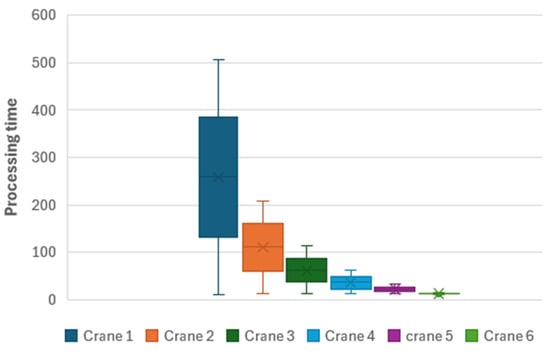
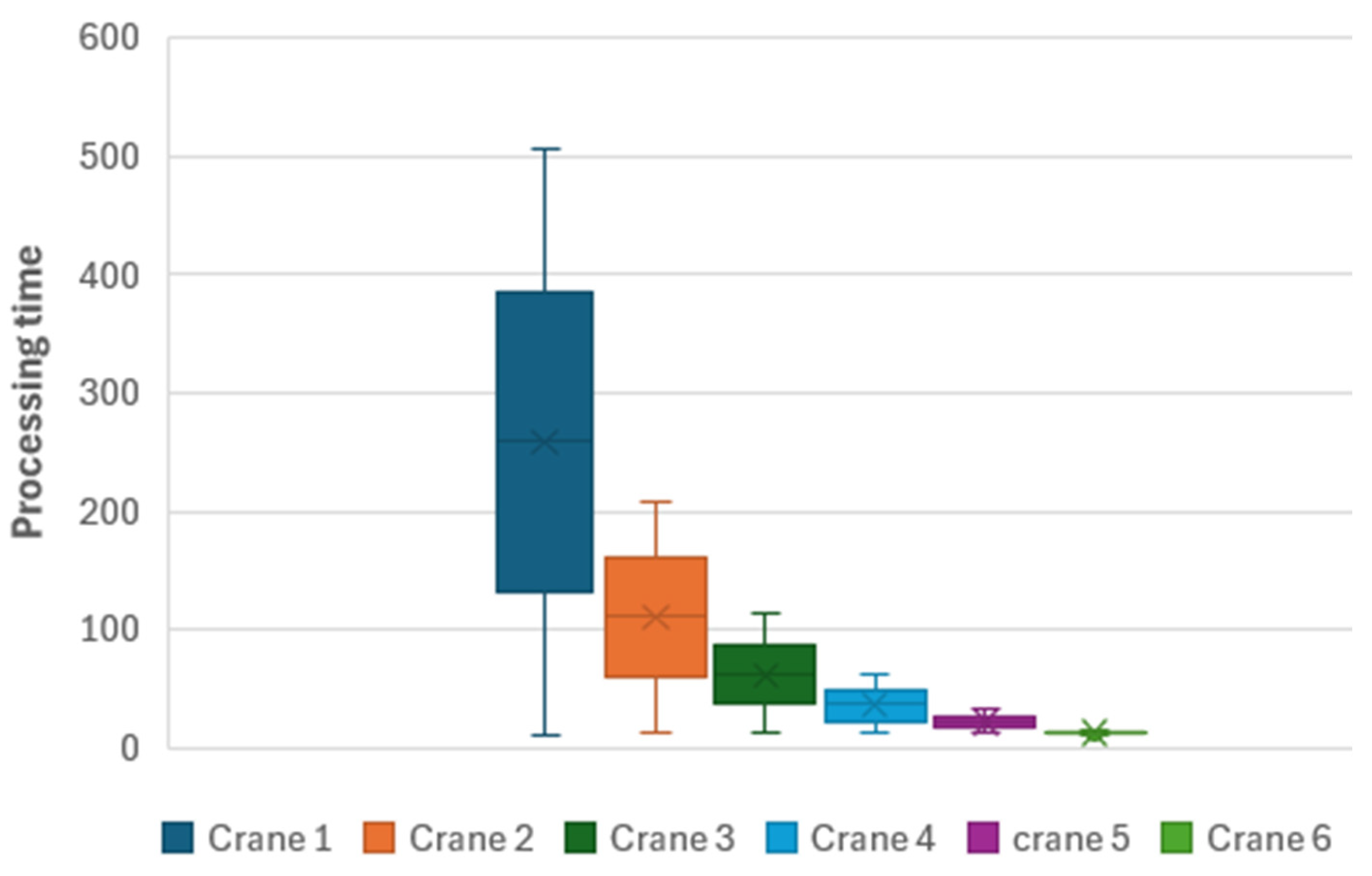
The total average processing time for (the time taken to complete) one order is 110.23 min. The average time taken to load and couple one TU to CU is 6 min. Utilisation time of the crane (the % of time the crane spent working) is 98%, and both cranes were used.
4.3.3. Case 3: With Only One Crane Available
The total average processing time for (the time taken to complete) one order is 258.83 min. The average time taken to load and couple one TU to CU is 6 min. Utilisation time of the crane (the % of time the crane spent working) is 99%.
4.3.4. Case 4: With Four Cranes Available
The total average processing time for (the time taken to complete) one order is 36.65 min. The average time taken to load and couple one TU to CU is 6 min. Utilisation time of the crane (the % of time the crane spent working) is 96%. And all four cranes were busy.
4.3.5. Case 5: With Five Cranes Available
The total average processing time for (the time taken to complete) one order is 21.06 min. The average time taken to load and couple one TU to CU is 6 min. Utilisation time of the crane (the % of time the crane spent working) is 94%. And all five cranes were busy.
4.3.6. Case 6: With Six Cranes Available
The total average processing time for (the time taken to complete) one order is 12. 67 min. The average time taken to load and couple one TU to CU is 6 min. Utilisation time of the crane (the % of time the crane spent working) is 92%. And all six cranes were busy. Therefore, for scenario 3, it is better to use six cranes to reduce order processing time.
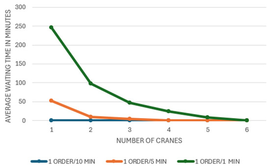
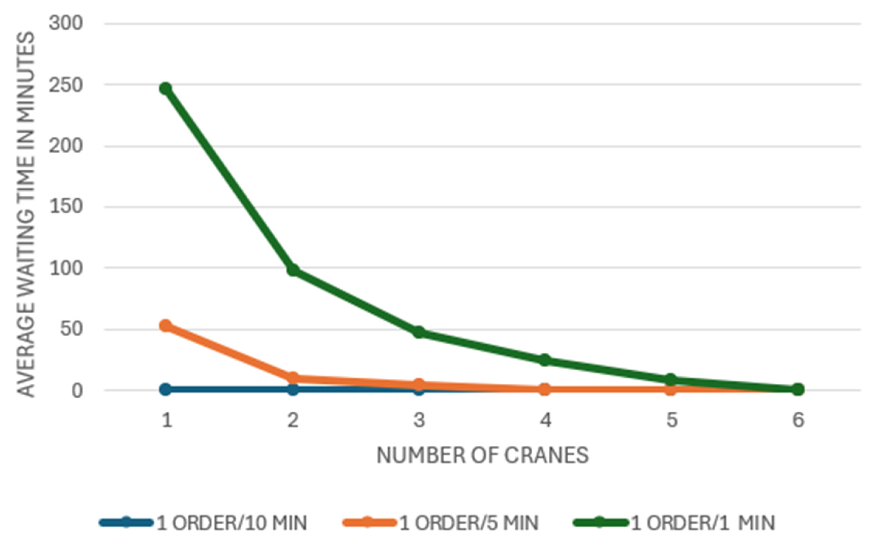
All results are shown in the following graph:
The following graph and table show the distribution and 95th percentile for the example (scenario 3).
Error bars represent 95% confidence intervals obtained from multiple independent simulation replications.
While the results indicate that increasing the number of cranes significantly reduces waiting times, the marginal benefit decreases once the number of cranes exceeds five units. In the configuration with six cranes, the utilisation rate drops to approximately 92%, indicating potential underutilization of equipment. In practical terminal design, this trade-off must be evaluated in terms of investment costs, operational efficiency, and acceptable service levels.
The obtained results illustrate the potential operational efficiency of the automated pod-handling concept. They are shown in the Figure 8 and Figure 9. Compared with conventional intermodal terminal operations, where handling processes often require complex coordination between trucks, trains, and cranes, the automated matching of transport units and carrier vehicles may reduce waiting times and improve terminal throughput. These findings indicate that automated modular handling concepts could contribute to more efficient rail freight operations, particularly in environments with high transport demand.
Figure 8.
Dependence graph between the number of cranes and the waiting time.
Figure 9.
Statistical evaluation for the selected scenario 3 with description of the 95th percentile.
Total summary of all scenarios is shown in the following Table 1.
Table 1.
Statistical evaluation for each scenario.
5. Discussion
The simulation results validate the operational logic of the PODs4RAIL handling concept and demonstrate the critical relationship between demand intensity and terminal resource allocation. The system performs efficiently under low-demand conditions with minimal infrastructure; however, it becomes highly sensitive to resource constraints as demand increases. These findings highlight the necessity of adaptive terminal design and provide a basis for discussing theoretical, managerial, and policy-related implications of modular rail-based transport systems.
5.1. Implications for Theory
This study contributes to the growing body of research on automated and modular rail transport systems by extending existing knowledge in three key areas: operational modelling, system flexibility, and multimodal integration.
First, the research advances the theoretical understanding of terminal operations in modular transport systems by introducing a structured, simulation-based representation of automated pod-handling processes. Unlike traditional intermodal systems, where loading units are passively transferred, the proposed system actively integrates transport units and carrier units through automated coupling, requiring a new conceptualisation of terminal operations as synchronised cyber-physical processes.
Second, the findings contribute to the theory of transport system flexibility by demonstrating how decoupling transport units from propulsion units enables demand-responsive logistics. The results show that system performance is not linearly dependent on infrastructure capacity but instead exhibits threshold behaviour, where insufficient resources lead to rapid performance degradation. This supports emerging theoretical perspectives on adaptive and scalable logistics systems.
Third, the study contributes to research on multimodal transport integration by illustrating how modular rail systems can bridge the gap between high-capacity rail transport and flexible last-mile solutions. The proposed concept aligns with Mobility as a Service (MaaS) frameworks and supports the transition toward decentralised and digitally coordinated logistics networks.
Overall, the study provides a foundation for future theoretical work on automated logistics systems, particularly in the context of modular, autonomous, and service-oriented transport architectures.
5.2. Implications for Managers
The results of this study provide several practical insights for logistics and terminal managers responsible for designing and operating intermodal transport systems.
A key finding is the strong dependency between demand intensity and required handling capacity. Managers must carefully balance infrastructure investment with expected demand levels, as under-dimensioned systems lead to significant delays, while over-dimensioned systems result in underutilised resources and increased operational costs.
The study also highlights the importance of scalability. Modular rail systems require flexible terminal configurations that allow dynamic adjustment of resources, such as the number of cranes or handling units, in response to real-time demand fluctuations. This suggests that future terminals should be designed with modular infrastructure and supported by advanced control systems capable of demand forecasting and adaptive scheduling. Furthermore, automation plays a critical role in improving operational efficiency and consistency. The implementation of automated coupling, digital control systems, and integrated handling procedures reduces human intervention, minimises errors, and enables higher throughput. However, managers must also consider the complexity, reliability, and maintenance requirements associated with such technologies.
Finally, the findings emphasise that modular rail systems can offer competitive advantages in terms of speed, flexibility, and service quality compared to conventional rail freight. This creates opportunities for logistics providers to develop new service models, particularly in decentralised and time-sensitive logistics applications.
5.3. Implications for Policymakers
The proposed modular rail transport concept has important implications for transport policy and infrastructure planning.
First, the results support the development of more flexible and decentralised rail systems, which can complement existing high-capacity rail corridors. Policymakers should consider supporting the integration of modular transport concepts into national and European transport strategies, particularly in the context of sustainable mobility and decarbonisation goals.
Second, the adoption of automated terminal operations requires the establishment of appropriate regulatory frameworks addressing safety, interoperability, and standardisation. This includes the development of standards for automated coupling systems, communication protocols, and digital control architectures.
The public investment strategies should reflect the need for scalable infrastructure. Rather than focusing solely on large, centralised terminals, policymakers should support the development of smaller, distributed hubs capable of handling modular transport units efficiently. Finally, the transition toward automated and digitalised logistics systems raises broader societal and economic considerations, including workforce transformation, data governance, and system resilience. Policymakers play a key role in facilitating this transition through targeted funding, regulatory support, and innovation programmes.
5.4. Limitations of the Study and Future Research Directions
This study is subject to several limitations that should be considered when interpreting the results.
First, the simulation model is based on a simplified representation of terminal operations and assumes ideal operating conditions without equipment failures, delays, or human-related disruptions. In real-world environments, such factors may significantly affect system performance.
Second, the model does not explicitly consider spatial constraints, such as crane interference, terminal layout limitations, or safety distances, which may restrict the achievable level of parallel operations in practice.
Third, the analysis is based on a finite number of transport orders rather than a steady-state system evaluation. As a result, the findings reflect short-term operational behaviour rather than long-term equilibrium conditions.
Fourth, economic aspects, such as investment costs, operational expenses, and cost–benefit trade-offs, were not included in the analysis and should be considered in the future.
Future research should address these limitations by incorporating more detailed spatial modelling, stochastic disruptions, and economic evaluation. Additionally, further work is needed to validate the proposed handling concept in real-world pilot implementations and to explore its integration with broader multimodal transport systems.
6. Conclusions
This paper presented a simulation-based analysis of an automated handling concept for modular rail freight transport units within a terminal environment. The study focused on evaluating the operational performance of the proposed system by analysing the relationship between crane capacity and the average waiting time of transport units. The developed simulation model enabled the investigation of different operational scenarios with varying arrival intervals and numbers of handling cranes.
The results indicate that crane capacity has a significant impact on the operational efficiency of the terminal. Increasing the number of cranes leads to a substantial reduction in waiting times, particularly in scenarios with higher order arrival frequencies. However, the improvement becomes progressively smaller as additional cranes are introduced, suggesting that an optimal balance between infrastructure capacity and equipment utilisation must be considered when designing such terminals.
The findings demonstrate the potential of automated handling systems for modular rail freight concepts to improve the efficiency of terminal operations by reducing operational delays and improving the coordination of loading and unloading processes. These improvements may contribute to more flexible and scalable rail freight systems capable of supporting future decentralised logistics networks.
Future work should extend the simulation model by incorporating additional operational factors, such as equipment failures, stochastic demand variations, and economic evaluation of terminal infrastructure configurations, in order to provide a more comprehensive assessment of the proposed concept.
Author Contributions
Conceptualisation, K.R. and W.S.R.; methodology, M.S.; numerical simulations, M.S. and W.S.R.; experimental data processing, W.S.R. and K.R.; writing—original draft preparation, K.R. and W.S.R. All authors have read and agreed to the published version of the manuscript.
Funding
This project has received funding from the European Union’s Horizon Europe research and innovation programme under Grant Agreement No. 101121853.
Institutional Review Board Statement
Not applicable.
Informed Consent Statement
Not applicable.
Data Availability Statement
The raw data supporting the conclusions of this article will be made available by the authors on request.
Acknowledgments
This project has received funding from the European Union’s Horizon Europe research and innovation programme under Grant Agreement No. 101121853.
Conflicts of Interest
The authors declare no conflicts of interest.
Abbreviations
The following abbreviations are used in this manuscript:
| TU | Transport Unit |
| CU | Carrier Unit |
| MaaS | Mobility as a Service |
| WMS | Warehouse Management System |
| LCS | Loading Crane System |
| AGV | Automated Guided Vehicle |
| RFID | Radio Frequency Identification |
| GPS | Global Positioning System |
References
- Okyere, S.; Yang, J.; Adams, C.A. Optimizing the Sustainable Multimodal Freight Transport and Logistics System Based on the Genetic Algorithm. Sustainability 2022, 14, 11577. [Google Scholar] [CrossRef] [Scilit]
- Schlaht, J. Future of multi-modal mobility. In 20th International Stuttgart Symposium; Bargende, M., Reuss, H.C., Wagner, A., Eds.; Proceedings; Springer Vieweg: Wiesbaden, Germany, 2020; pp. 57–65. [Google Scholar] [CrossRef] [Scilit]
- Li, J.; Dong, J.; Ren, R.; Chen, Z. Modeling Resilience of Metro-Based Urban Underground Logistics System Based on Multi-Layer Interdependent Network. Sustainability 2024, 16, 9892. [Google Scholar] [CrossRef] [Scilit]
- de Morais, G.R.; Calil, Y.C.D.; de Oliveira, G.F.; Saldanha, R.R.; Maia, C.A. A Sustainable Location Model of Transshipment Terminals Applied to the Expansion Strategies of the Soybean Intermodal Transport Network in Brazil. Sustainability 2023, 15, 1063. [Google Scholar] [CrossRef] [Scilit]
- Jasińska-Gospodarczyk, I.; Słowiński, N.; Gajewska, N.; Sowa, M. Sustainable Development of Intermodal Freight Transportation through the Integration of Logistics Flows in Ukraine and Poland. Sustainability 2024, 16, 267. [Google Scholar] [CrossRef] [Scilit]
- Fedorko, G.; Molnár, V.; Mikušová, N.; Strohmandl, J.; Kižik, T. Simulation of Handling Operations in Marine Container Terminals for the Purposes of a Profession Simulator. J. Mar. Sci. Eng. 2023, 11, 2264. [Google Scholar] [CrossRef] [Scilit]
- Rožić, T.; Ivanković, B.; Bajor, I.; Starčević, M. A Network-Based Model for Optimization of Container Location Assignment at Inland Terminals. Appl. Sci. 2022, 12, 5833. [Google Scholar] [CrossRef] [Scilit]
- Chen, H.; Liu, W.; Oldache, M.; Pervez, A. Research on Train Loading and Unloading Mode and Scheduling Optimization in Automated Container Terminals. J. Mar. Sci. Eng. 2024, 12, 1415. [Google Scholar] [CrossRef] [Scilit]
- Sun, Z.; Zhai, Y.; Li, H.; Pei, Y. Automated Rail–Water Intermodal Transport Container Terminal Handling Equipment Cooperative Scheduling Based on Bidirectional Hybrid Flow-Shop Scheduling Problem. Comput. Ind. Eng. 2023, 186, 109696. [Google Scholar] [CrossRef] [Scilit]
- Grosche, T.; Schröder, M.; Bär, M. Evaluating the Effects of Automation Components in Service Networks of Rail Freight. Transp. Res. Procedia 2021, 52, 317–324. [Google Scholar] [CrossRef] [Scilit]
- Yang, X.; Johansson, M.; Olsson, N. An Approach for Seamless Rail Freight: Integration of Virtual Coupling and Digital Automatic Coupling. Comput. Ind. Eng. 2026, 213, 111810. [Google Scholar] [CrossRef] [Scilit]
- Pfaff, R.; Schmidt, B.D.; Enning, M. Automation of the Freight Wagon Subsystem. In New Research on Railway Engineering and Transportation; IntechOpen: London, UK, 2023. [Google Scholar] [CrossRef] [Scilit]
- Khan, A.; Fröidh, O.; Krmac, E. Determinants of Autonomous Train Operation Adoption in Rail Freight: Knowledge-Based Assessment with Delphi–ANP Approach. Soft Comput. 2023, 27, 14821–14839. [Google Scholar] [CrossRef] [Scilit]
- Park, N.; Kim, J.; Lee, H. Design and Simulation of a New Intermodal Automated Container Transport System Considering Different Operation Scenarios of Container Terminals. J. Mar. Sci. Eng. 2020, 8, 233. [Google Scholar] [CrossRef] [Scilit]
- Fedorko, G.; Molnár, V.; Honus, S.; Neradilová, H. Contingency Plans for the Wood Supply Chain Based on Bottleneck and Queuing Time Analyses of a Discrete Event Simulation. Forests 2020, 11, 396. [Google Scholar] [CrossRef] [Scilit]
- Sánchez, M.; Escudero, A.; Barber, F. Simulation of Heuristics for Automated Guided Vehicle Task Sequencing with Resource Sharing and Dynamic Queues. Mathematics 2024, 12, 271. [Google Scholar] [CrossRef] [Scilit]
- Gawlik, R.; Rudek, R.; Zajdel, R. Experimental Evaluation of AGV Dispatching Methods in an Agent-Based Simulation Environment and a Digital Twin. Appl. Sci. 2023, 13, 6171. [Google Scholar] [CrossRef] [Scilit]
- Faria de Oliveira, G.; Saldanha, R.R.; Maia, C.A. Optimizing Resources of Multimodal Transport Terminal for Material Flow Service. Sustainability 2020, 12, 6545. [Google Scholar] [CrossRef] [Scilit]
- Barker, K.; Jović, M.; Ramírez-Marquez, J.E. Masterplanning at the Port of Dover: The Use of Discrete-Event Simulation in Managing Road Traffic. Sustainability 2020, 12, 1067. [Google Scholar] [CrossRef] [Scilit]
- Ahmed, M.; Hammad, A.; Moselhi, O. Utilizing Autonomous Vehicles to Reduce Truck Turn Time in Ports: Application to the Port of Montréal. Systems 2025, 13, 1031. [Google Scholar] [CrossRef] [Scilit]
- Bierwirth, C.; Meisel, F.; Schmid, M. Simulated Annealing Integrated with Discrete-Event Simulation for Berth Allocation in Bulk Ports under Demurrage Constraints. Logistics 2024, 6, 352. [Google Scholar] [CrossRef] [Scilit]
- Marinov, M.; Viegas, J. A mesoscopic simulation modelling methodology for analysing rail freight terminals. Simul. Model. Pract. Theory 2011, 19, 516–539. [Google Scholar] [CrossRef] [Scilit]
- Boysen, N.; Fliedner, M.; Jaehn, F.; Pesch, E. Scheduling Freight Trains: Models and Methods. Eur. J. Oper. Res. 2012, 222, 221–231. [Google Scholar] [CrossRef] [Scilit]
- Rodrigue, J.-P.; Notteboom, T.; Slack, B. The Geography of Transport Systems, 5th ed.; Routledge: New York, NY, USA, 2020. [Google Scholar]
- Ballis, A.; Golias, J. Comparative evaluation of existing and innovative rail–road freight transport terminals. Transp. Res. Part A Policy Pract. 2002, 36, 593–611. [Google Scholar] [CrossRef] [Scilit]
- Steenken, D.; Voß, S.; Stahlbock, R. Container terminal operation and operations research—A classification and literature review. OR Spectr. 2004, 26, 3–49. [Google Scholar] [CrossRef] [Scilit]
- Zhang, R.; Wiegmans, B.; Tavasszy, L. Optimization of Rail–Road Intermodal Freight Transport Networks under Demand Uncertainty. Sustainability 2019, 11, 4572. [Google Scholar] [CrossRef] [Scilit]
- Gharehgozli, A.H.; Roy, D.; de Koster, R. Sea Container Terminals: New Technologies and OR Models. Marit. Econ. Logist. 2016, 18, 103–140. [Google Scholar] [CrossRef] [Scilit]
- Angeloudis, P.; Bell, M.G.H. A Review of Container Terminal Simulation Models. Marit. Policy Manag. 2011, 38, 523–540. [Google Scholar] [CrossRef] [Scilit]
- Dragović, B.; Tzannatos, E.; Park, N.K. Simulation Modelling in Ports and Container Terminals: Literature Overview and Analysis by Research Field. Marit. Policy Manag. 2017, 44, 878–902. [Google Scholar] [CrossRef] [Scilit]
- Carlo, H.J.; Vis, I.F.A.; Roodbergen, K.J. Storage Yard Operations in Container Terminals: Literature Overview, Trends, and Research Directions. Eur. J. Oper. Res. 2014, 235, 412–430. [Google Scholar] [CrossRef] [Scilit]
- Notteboom, T.; Pallis, A.; Rodrigue, J.-P. Disruptions and Resilience in Global Container Shipping and Ports: The COVID-19 Pandemic versus the 2008–2009 Financial Crisis. Marit. Econ. Logist. 2021, 23, 179–210. [Google Scholar] [CrossRef] [Scilit]
- Ambra, T.; Caris, A.; Macharis, C. Towards Freight Transport System Unification: Reviewing and Combining the Advancements in the Physical Internet and Synchromodal Transport Research. Int. J. Prod. Res. 2019, 57, 1606–1623. [Google Scholar] [CrossRef] [Scilit]
- Crainic, T.G.; Kim, K.H. Intermodal Transportation. In Transportation; Barnhart, C., Laporte, G., Eds.; Elsevier: Amsterdam, The Netherlands, 2007; pp. 467–537. [Google Scholar] [CrossRef] [Scilit]
- Woxenius, J. Generic Framework for Transport Network Designs: Applications and Treatment in Intermodal Freight Transport Literature. Transp. Rev. 2007, 27, 733–749. [Google Scholar] [CrossRef] [Scilit]
- Macharis, C.; Bontekoning, Y.M. Opportunities for OR in Intermodal Freight Transport Research: A Review. Eur. J. Oper. Res. 2004, 153, 400–416. [Google Scholar] [CrossRef] [Scilit]
- Van Riessen, B.; Negenborn, R.R.; Dekker, R.; Lodewijks, G. Service Network Design for an Intermodal Container Network with Flexible Transshipment and Transport Times. Transp. Res. Part B Methodol. 2015, 80, 258–280. [Google Scholar] [CrossRef] [Scilit]
- Konings, R.; Kreutzberger, E.; Maras, V. Major Issues in European Freight Transport: Intermodal Transport and Logistics. Transp. Rev. 2013, 33, 725–736. [Google Scholar] [CrossRef] [Scilit]
- Beškovnik, B.; Twrdy, E. Managing the Efficiency of Container Terminals by Using Simulation Modeling. Transport 2010, 25, 235–243. [Google Scholar] [CrossRef] [Scilit]
- Gharehgozli, A.; Zaerpour, N.; de Koster, R. Container Terminal Layout Design: Transition and future. Marit. Policy Manag. 2017, 44, 609–628. [Google Scholar] [CrossRef] [Scilit]
- Crainic, T.G.; Ricciardi, N.; Storchi, G. Advanced Freight Transportation Systems for Congested Urban Areas. Transp. Res. Part C Emerg. Technol. 2004, 12, 119–137. [Google Scholar] [CrossRef] [Scilit]

Disclaimer/Publisher’s Note: The statements, opinions and data contained in all publications are solely those of the individual author(s) and contributor(s) and not of MDPI and/or the editor(s). MDPI and/or the editor(s) disclaim responsibility for any injury to people or property resulting from any ideas, methods, instructions or products referred to in the content. |
© 2026 by the authors. Licensee MDPI, Basel, Switzerland. This article is an open access article distributed under the terms and conditions of the Creative Commons Attribution (CC BY) license.