


Abstract
Interferometric fiber-optic hydrophones are widely deployed in passive underwater acoustic detection systems due to their high sensitivity, broad dynamic range, and immunity to electromagnetic interference. However, their adoption in active acoustic systems has been largely constrained by the limited operational bandwidth of conventional architectures. Through coupled acoustic–structural simulations, this work identifies the operational bandwidth bottleneck as arising from low-order mechanical resonance of high-modulus mandrel structures combined with acoustic cavity resonance and near-field scattering within the enclosed cylindrical geometry. To address these limitations, an optimized push–pull mandrel structure, featuring a miniaturized profile of φ16 mm × 16 mm and a low-acoustic-impedance material, is implemented to eliminate mechanical resonance within the operational bandwidth. Additionally, an integrated acoustic metamaterial liner is incorporated into the inner tube to mitigate scattering and reverberation effects. Experimental characterization of the prototype demonstrates an average phase sensitivity of −132 dB re 1 rad/μPa, with fluctuations below ±1.5 dB across 20 Hz to 31.5 kHz. Utilizing a custom-built demodulation system, the hydrophone achieves a minimum detectable pressure of 42 dB re 1 µPa/√Hz (126 µPa/√Hz) at 20 Hz and 27 dB re 1 µPa/√Hz (22 µPa/√Hz) above 2 kHz, remaining over 28 dB below the deep-sea state zero ambient noise floor at 20 Hz, and hence confirms its passive acoustic monitoring capability. In the high-frequency regime above 2 kHz, the hydrophone maintains ±1.5 dB sensitivity flatness with a horizontal directivity variation of only ±1.51 dB at 30 kHz, providing a robust platform for broadband active acoustic applications, including active sonar, underwater acoustic imaging and acoustic communications. These results establish a viable pathway toward next-generation dual-mode underwater acoustic systems requiring both high-fidelity passive listening and broadband active detection.
1. Introduction
Interferometric fiber-optic hydrophones (FOHs) have emerged as critical tools for underwater acoustic detection due to their exceptional sensitivity, immunity to electromagnetic interference, and suitability for large-scale multiplexed arrays [1,2,3,4]. While extensively employed in passive systems for marine monitoring [5,6,7], seismic surveys [8,9,10,11], and underwater target detection [2,3,4,12,13], their deployment in active acoustic systems, including sonar imaging and underwater acoustic communication, has been limited by bandwidth and sensitivity flatness constraints. These limitations primarily stem from low-order mechanical resonance of high-modulus mandrel structures combined with acoustic cavity resonance and near-field scattering within the enclosed cylindrical geometry in conventional designs.
The evolution of FOHs has been marked by progressive improvements in sensitivity [14,15,16], multiplexing capacity [17,18,19,20], and environmental robustness [21,22]. Notably, early work by Bucaro et al. established the feasibility of fiber-optic acoustic transduction through sound-induced phase modulation in a submerged fiber coil, with sensitivity comparable to leading hydrophones of the time [23]. Subsequent efforts have been spent on enhancing sensitivity through mandrel-based designs. Cranch et al. developed large-scale interferometric arrays for seabed applications, achieving −127.5 dB re 1 rad/μPa sensitivity over 10–1000 Hz but with bandwidth limited by structural resonance [24]. A breakthrough came from Yang et al., who introduced a push–pull interferometric hydrophone with a bilayer elastic mandrel, achieving −134.39 dB re 1 rad/μPa sensitivity and a 1 Hz–2 kHz bandwidth, but with resonance-induced fluctuations at low frequencies [25]. Meanwhile, Li et al. optimized mandrel winding ratios and dual-layer structures to achieve −113 dB re 1 rad/μPa sensitivity and ±1.5 dB flatness from 10 Hz to 1 kHz, yet high-frequency performance remained unaddressed [2]. Similarly, Plotnikov et al. demonstrated a thin-cable FOH array with −116 dB re 1 rad/μPa sensitivity at 495 Hz and direction-of-arrival estimation capabilities, though operational bandwidth was confined below 500 Hz [3]. Beyond mechanics, considerable attention has been paid to fiber transmission physics. Birri et al. and Savović et al. reported that thermally induced bend loss and temperature-dependent mode coupling introduce non-negligible noise and bandwidth instability under environmental fluctuations [26,27].
Collectively, despite mature strategies for sensitivity enhancement, the fundamental challenge of jointly achieving a wide operational bandwidth, high sensitivity, and a flat frequency response remains largely unaddressed. To bridge this gap, we propose an optimized push–pull configuration featuring a miniaturized, low-acoustic-impedance mandrel to suppress mechanical resonance and incorporating an internal acoustic metamaterial liner [28,29,30] to mitigate scattering and reverberation. Experimental characterization validates an average sensitivity of −132 dB re 1 rad/μPa with ±1.5 dB flatness over 20 Hz to 31.5 kHz, representing an order-of-magnitude extension in flat-response bandwidth relative to conventional FOHs [2,3,24,25]. By delivering an minimum detectable pressure (MDP) over 28 dB below the deep-sea state zero [31] ambient noise floor at 20 Hz, alongside a flat frequency response and minimal directivity distortion above 2 kHz, this architecture establishes a viable pathway toward next-generation dual-mode underwater acoustic systems unifying high-signal-to-noise-ratio passive detection at low frequencies with high-fidelity signal acquisition at high frequencies.
2. Design and Optimization
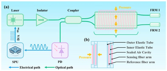
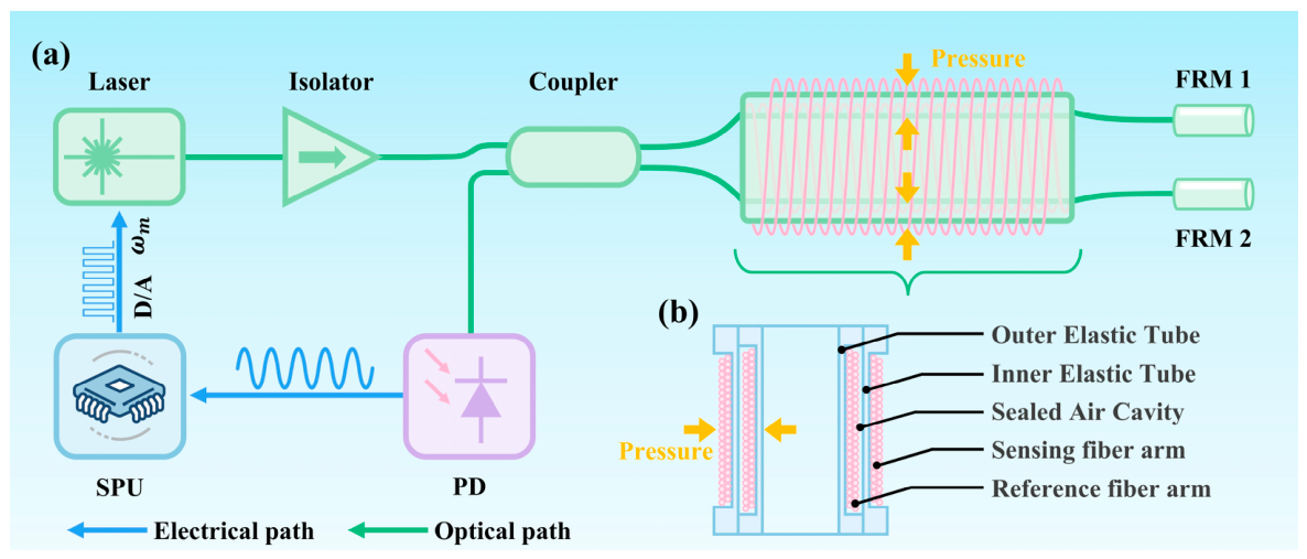
The interferometric fiber-optic hydrophone is configured as a Michelson interferometer with a push–pull sensing architecture, as shown in Figure 1a, comprising a narrow-linewidth laser source, a fiber-optic coupler, two fiber arms terminated with Faraday Rotator Mirrors (FRMs), a photodetector, and a signal processing unit (SPU). The laser source emits highly coherent light at wavelength λ, which is split by a fiber coupler into two optical beams, one of which travels through the reference fiber arm while the other propagates through the sensing fiber arm. As illustrated in Figure 1b, the two fiber arms are wound on the inner and outer elastic tubes, respectively, forming a push–pull configuration. Both arms are terminated with FRMs that reflect the light with a 90° polarization rotation, effectively suppressing polarization-induced fading by ensuring the return state of polarization (SOP) remains orthogonal to the input SOP regardless of birefringence fluctuations in the fiber link. The counter-propagating beams recombine at the coupler, producing an interference pattern detected by a photodetector (PD) and processed by an SPU.
Figure 1.
Schematic of the interferometric FOH. (a) A Michelson interferometer configuration, (b) a push–pull sensing mechanism.
When an acoustic pressure p acts on the hydrophone probe, the compliant mandrel undergoes radial deformation. In the push–pull configuration shown in Figure 1b, the inner elastic tube expands outward under tensile loading while the outer tube contracts inward due to the pressure differential across the air-backed cavity. Optical fibers wound on the respective tubes consequently experience opposite axial strains linearly proportional to the acoustic pressure p, one in tension and the other in compression, which doubles the acoustic-to-phase transduction efficiency:
where L1 and L2 represent the total length of the two fiber arms, respectively. The optical phase accumulated in a fiber segment is given by
where n is the effective refractive index, L is the length of the fiber arm, and λ is the operating wavelength. An acoustic pressure induces both axial elongation and a strain-dependent refractive index shift on the fiber arms via the elasto-optic effect. The resulting phase variation in each arm is expressed as
where is the length variation in the fiber arm proportional to and is the refractive index shift in the fiber core proportional to . In the push–pull mandrel illustrated in Figure 1b, the inner and outer sensing fiber arms undergo equal-magnitude but opposite-sign strains, such that the net phase difference at the coupler is given by
where and are the phase modulations of the two fiber arms, respectively. Equation (4) reveals the core advantage of the push–pull architecture, where the acoustic-induced phase difference is doubled compared to a single-arm modulation scheme, directly improving the hydrophone sensitivity by a factor of two.
The two counter-propagating beams recombine at the fiber coupler. For a 3 dB coupler with an equal splitting ratio and neglecting insertion loss, the output optical power at the photodetector is given by
where Iin is the incident optical intensity, is the fringe visibility of the interferometer, is the initial phase offset between the two fiber arms, is the acoustic-induced phase difference and represents phase noise due to temperature and environmental perturbations.
The acoustic pressure is recovered from the interference intensity signal described by Equation (5) via standard interferometric demodulation, including the phase-generated carrier (PGC) scheme or 3 × 3 coupler arctangent algorithm [5,13]. The hydrophone phase sensitivity is defined following established convention as [1,4]
where denotes the phase difference induced by acoustic pressure and p0 = 1 μPa is the reference acoustic pressure used for quantitative characterization.
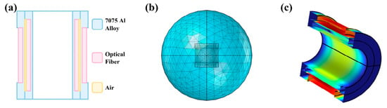
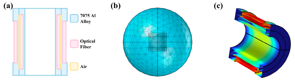
To quantify the performance limits of conventional designs, a numerical model of an interferometric fiber-optic hydrophone is developed using COMSOL Multiphysics 6.0. Multiphysics. As shown in Figure 2a, the model comprises two concentric thin-walled hollow cylinders separated by an air gap, with the two sensing fiber arms represented as thin elastic layers wound around the outer and inner cylinders, respectively. Figure 2b presents the corresponding simulation domain, where the acoustic–structure interaction interface couples the ambient fluid pressure field to the mechanical deformation of the cylinders and fiber layers, while the Solid Mechanics module computes the induced strain and displacement. A frequency-domain study with a parametric sweep over the acoustic excitation frequency is conducted to evaluate the deformation response. As visualized in Figure 2c, the total axial strain of the fiber layers, serving as the key transduction parameter for sensitivity and bandwidth evaluation, is calculated and visualized, demonstrating the enhanced sensitivity of the push–pull configuration through opposite deformations in the two fiber layers. This simplified yet effective model provides valuable insights into the mechanical response of the hydrophone responsible for bandwidth limitation, offering a robust framework for structural optimization toward high-frequency underwater acoustic sensing.
Figure 2.
Numerical modeling and analysis of the FOH. (a) The cross-section diagram of the numerical model, (b) the simulation domain, and (c) the deformation distribution under acoustic pressure.
To quantify the intrinsic performance limits of conventional mandrel-based FOHs, a numerical baseline model is established with key geometric dimensions listed in Table 1. The sensing arms adopt the BI1017-A fiber from Yangtze Optical Fiber and Cable Company (Wuhan, China), featuring a standard 60 µm cladding diameter and 100 µm acrylate coating diameter, while the hydrophone skeleton is constructed from aluminum alloy 7075. The mechanical properties of these two materials are summarized in Table 2. It should be noted that the mechanical parameters of the fiber layers are equivalent properties derived from a multilayer homogenization of the core and cladding [32,33]. In the Multiphysics framework setup, the external water region and the internal air cavity are defined as pressure acoustics domains, while the fiber layers and mandrel skeleton constitute the solid mechanics domain. All fluid–solid interfaces are assigned acoustic–structure boundary conditions to enable full coupling of the acoustic pressure field to the structural strain. Within the pressure acoustics domain, a 1 Pa plane wave excitation is imposed via a spherical wave radiation setting, with the incident direction initialized perpendicular to the hydrophone central axis, and the azimuthal angle is parametrized to vary the acoustic angle of arrival. In the solid mechanics domain, both circular end faces of the mandrel skeleton are set to fixed constraints to provide mechanical grounding. A frequency-domain sweep (20 Hz–31.5 kHz) is performed to compute the total axial strain in the fiber layers at each step, which is then analytically converted to phase sensitivity to obtain the hydrophone’s frequency response and angular directivity characteristics.
Table 1.
Geometric parameters of the FOH used in modeling.
Table 2.
Material parameters of the FOH used in modeling.
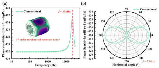
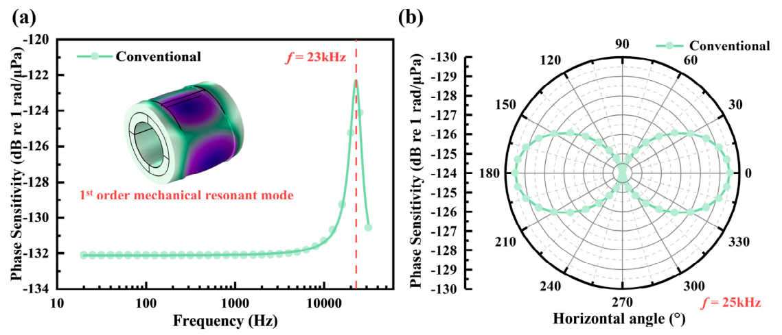
As shown in Figure 3a, the simulation results demonstrate that the phase sensitivity–frequency response curve of the hydrophone remains nearly flat below 10 kHz. However, above 10 kHz, the sensitivity gradually increases, peaking near 23 kHz before declining. This behavior indicates that the hydrophone’s response bandwidth is effectively limited to frequencies below 10 kHz, rendering it unsuitable for mid-to-high-frequency applications. Notably, the observed peak in the frequency response is attributed to the first-order mechanical resonance of the hydrophone skeleton. As illustrated in the inset of Figure 3a, the simulation results further confirm that the first-order mechanical mode of the skeleton occurs at approximately 23 kHz. Figure 3b presents the sensitivity of the FOH to acoustic waves from different directions. The results indicate a sensitivity difference of at least 5 dB (peak to peak) between waves incident perpendicularly and those incident parallelly to the sensor. These findings highlight the significant influence of the skeleton’s mechanical properties on the hydrophone’s frequency response characteristics, providing critical insights for optimizing its structural design and performance.
Figure 3.
Numerical simulation results of the conventional FOH. (a) Frequency response and (b) horizontal directivity at 25 kHz.
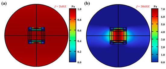
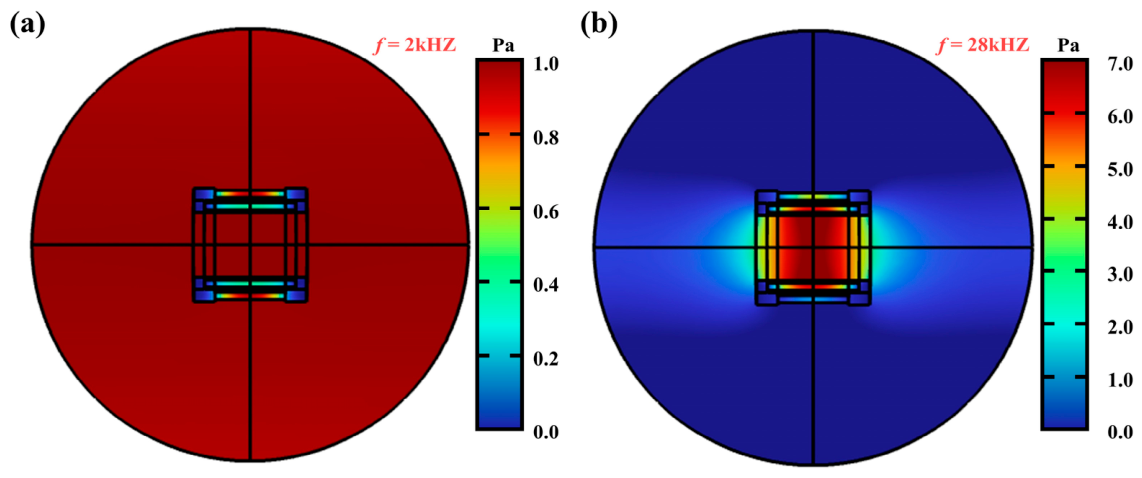
To evaluate the response of the FOH to high-frequency acoustic waves, frequency-domain acoustic simulations were performed, extracting near-field acoustic scattering characteristics of different frequencies. The acoustic field distribution at 2 kHz is uniform in the inner cavity of the FOH and closely matches the free-field profile without the sensor as shown in Figure 4a, while it exhibits a pronounced resonance phenomenon in the inner cavity of the FOH when the frequency of the incident acoustic wave increases to 28 kHz as illustrated in Figure 4b. The nonuniform acoustic field distribution leads to energy loss or enhancement, thereby introducing fluctuations in the frequency response as well as the directional response of the FOH. The acoustic resonance phenomenon is primarily attributed to acoustic impedance mismatch between the mandrel and the surrounding medium, as well as the interaction of high-frequency waves with the hydrophone’s geometric features. These findings highlight the critical need for structural and material optimization to mitigate these effects, minimize impedance mismatches, and hence achieve a broadband operational bandwidth.
Figure 4.
Numerical simulation results of the near-field distribution of the incident acoustic waves at (a) 2 kHz and (b) 28 kHz.
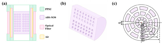
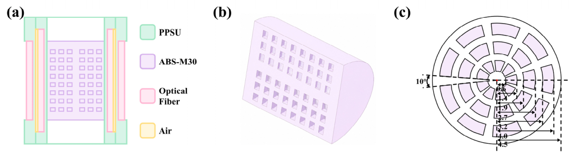
Building on the identified bottlenecks of low-order skeleton resonance and internal acoustic reverberation, an optimized push–pull mandrel is optimized to extend the flat operational bandwidth, as illustrated in Figure 5. A central supporting plate is integrated into the inner elastic tube to stiffen the structure against flexural deformation, effectively suppressing mechanical resonance within the target band. Simultaneously, a periodic acoustic metamaterial liner is embedded into the inner cavity to mitigate scattering and reverberation effects. To minimize impedance mismatches, the material of the push–pull structure is replaced by PPSU (polyphenylene sulfone resin), which exhibits exceptional mechanical strength, high-temperature resistance, ease of processability, and an acoustic impedance closely matching that of water. The acoustic metamaterial is made of engineering plastic ABS-M30, with cross-sectional and longitudinal sectional views of its internal structure as shown in Figure 5b,c. The cylindrical structure is filled with cavity structures arranged in a periodic pattern, as illustrated in Figure 5c. The material parameters of PPSU and ABS-M30 used in the optimized model are summarized in Table 3.
Figure 5.
Optimization of the FOH. (a) Enhanced push–pull structure, (b) perspective view and (c) cross-sectional view of the acoustic metamaterial insert.
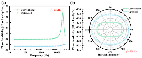
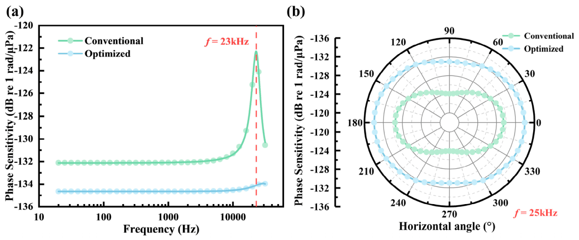
As a direct validation of the optimization strategy, Figure 6 presents the simulated performance of the improved FOH, integrating a PPSU mandrel, an internal supporting plate, and an acoustic metamaterial liner, while strictly preserving the geometry and fiber parameters specified in Table 1. As depicted in Figure 6a, the optimized design exhibits a significantly flattened phase sensitivity across a wideband spectrum from 20 Hz to 31.5 kHz, maintaining variations within an exceptional ±1.5 dB. Critically, the detrimental resonance at 23 kHz inherent to the original design is effectively suppressed. Correspondingly, Figure 6b demonstrates a dramatic improvement in directional uniformity. The optimized structure exhibits less than ±1.5 dB variation (peak to peak) between broadside and end-on incidences throughout the operational bandwidth, in stark contrast to the severe lobing (>5 dB variation) exhibited by the conventional configuration. These results confirm that the incorporation of low-impedance materials and metamaterial liners successfully mitigates mechanical and acoustic resonances, thereby extending the effective flat-response bandwidth and validating the optimized design for broadband underwater sensing.
Figure 6.
Numerical simulation results comparing the conventional and optimized FOHs. (a) Frequency response and (b) horizontal directivity at 25 kHz.
Table 3.
Material parameters of the optimized FOH used in modeling.
3. Fabrication and Characterization
3.1. Sensor Fabrication
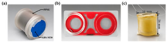
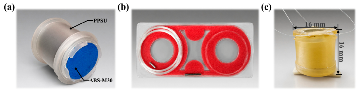
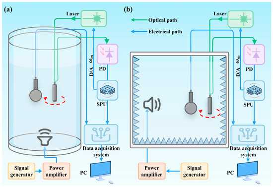
Based on the optimized design, a prototype of the enhanced push–pull interferometric FOH was fabricated, as illustrated in Figure 7. Figure 7a shows the exploded view of the components, highlighting the PPSU mandrel skeleton and the 3D-printed acoustic metamaterial insert (ABS-M30). Figure 7b presents the optical fiber interferometer ready for winding onto the mandrels. Figure 7c displays the fully packaged sensor ready for underwater testing, featuring a miniaturized profile of φ16 mm × 16 mm.
Figure 7.
Pictures of the fabricated FOH. (a) Exploded view showing the PPSU mandrel, metamaterial insert, (b) optical fiber interferometer and (c) fully packaged sensor ready for deployment.
The production process strictly adhered to the simulated parameters listed in Table 1. The mandrel skeletons were machined from PPSU using high-precision CNC milling. PPSU was selected not only for its close acoustic impedance match with water but also for its excellent dimensional stability. The acoustic metamaterial insert was fabricated via 3D printing using ABS-M30 material, ensuring the periodic cavity structures maintained tight tolerances. The sensing and reference fibers (BI1017-A, Yangtze Optical Fiber and Cable Company) were wound onto the cylinders under a controlled tension to prevent micro-bending losses while ensuring intimate contact with the mandrel surface.
3.2. Experimental Setup for Characterization
The acoustic performance of the fabricated FOH prototype, including phase sensitivity and directivity, was characterized following standardized calibration procedures in accordance with the national standard GB/T 42559-2023 for fiber-optic hydrophone testing. Due to the wide operational bandwidth, the measurement was partitioned into two complementary regimes covering 20 Hz to 2 kHz and 2 kHz to 31.5 kHz, respectively.
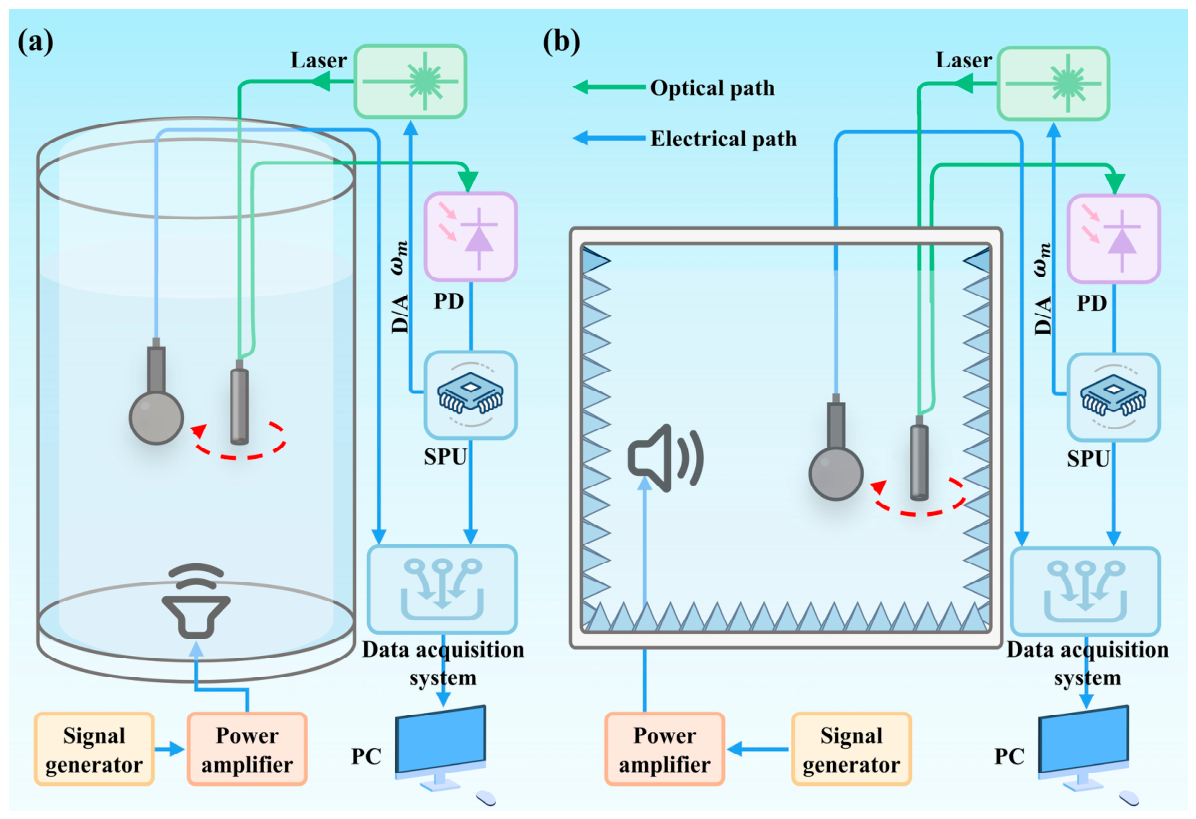
As schematically illustrated in Figure 8, the testing infrastructure comprised a signal generator, a broadband power amplifier driving an underwater acoustic projector, and a synchronized data acquisition system. For the low-frequency regime, measurements were conducted in a calibrated standing wave tube utilizing the transfer function comparison method with a reference hydrophone (B&K 8103), yielding an expanded uncertainty of plus or minus 0.6 dB traceable to national metrology standards, as shown in Figure 8a. For the high-frequency regime, measurements were performed in a standard anechoic water tank with the sensor rotated on a rotational stage, yielding an expanded uncertainty of plus or minus 1.0 dB, as shown in Figure 8b. The two datasets were cross-validated at the 2 kHz transition node with a residual offset below 0.5 dB, ensuring a total combined uncertainty below 1.5 dB across the full band.
Figure 8.
Schematic of the experimental setup for calibrating the FOH. (a) Standing wave tube setup for 20 Hz–2 kHz, and (b) anechoic water tank setup for 2 kHz–31.5 kHz, including the rotational stage for directivity testing.
During the calibration process, the standard reference hydrophone and the prototype FOH were positioned at the same depth and aligned to ensure they experienced identical acoustic excitation. The signal generator emitted discrete 1/3-octave center frequencies spanning 20 Hz to 2 kHz in the standing wave tube and 2 kHz to 31.5 kHz in the standard anechoic water tank. The electro-optic demodulation system of the FOH acquired the output signals. By comparing the sound pressure level obtained from the standard hydrophone with the phase amplitude of the output signal from the FOH, the phase sensitivity (in dB re 1 rad/μPa) was precisely calculated, as illustrated in the following equation:
where Mp denotes the phase sensitivity of the FOH, and M0 denotes the sensitivity of the reference standard hydrophone. ΔΦ and ΔV correspond to the output phase shift (rad) of the FOH and the output voltage (V) of the reference hydrophone, respectively.
Mp = M0 + 20log10(ΔΦ/ΔV)
To characterize the directivity pattern, the FOH was mounted on a computer-controlled rotational stage in the anechoic tank. The sensor was rotated horizontally in increments of 10° to change the horizontal angle relative to the incident acoustic wave. At specific test frequencies, the phase sensitivity was recorded for each angular position. This rotational scanning process allows the construction of a complete 360° polar response plot, revealing the sensor’s omnidirectionality or any angular dependence.
Additionally, the system noise floor was evaluated by acoustically isolating the FOH in a quiet environment with the acoustic projector disabled, thereby ensuring the measured spectrum reflects the noise of the PGC demodulation chain rather than ambient acoustic perturbations.
3.3. Results and Analysis
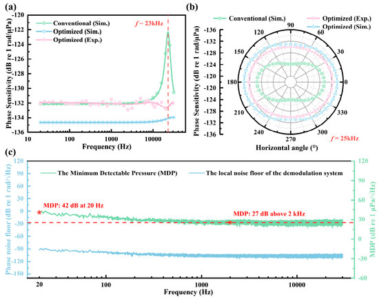
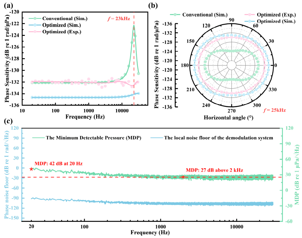
Figure 9 presents the core performance metrics of the fabricated FOH. Figure 9a compares the measured phase sensitivity against the simulated prediction and the conventional design. The experimental results demonstrate an average sensitivity of −132 dB re 1 rad/μPa across the entire 20 Hz to 31.5 kHz band, with a fluctuation of less than ±1.5 dB. This validates the effectiveness of the enhanced push–pull structure in suppressing mechanical resonance and the metamaterial layer in mitigating acoustic scattering. The measured phase sensitivity tracks the numerical prediction with a peak-to-peak deviation of ~3.0 dB, primarily ascribed to inherent discrepancies between the idealized isotropic material parameters assigned in simulation and the as-built mechanical properties of the manufactured ABS-M30 metamaterial, CNC-machined PPSU skeleton and fiber layers, compounded by minor variability in fiber winding tension affecting local strain transfer.
Figure 9.
Characterization results of the fabricated FOH. (a) Measured vs. simulated frequency response (20 Hz–30 kHz); (b) horizontal directivity pattern comparison at 25 kHz and 30 kHz (Conventional vs. Optimized); (c) local noise floor of the demodulation system and calculated minimum detectable pressure (MDP). Sim. denotes simulation, and Exp. denotes experiment.
Figure 9b presents the measured horizontal directivity of the optimized FOH at 25 kHz, obtained via stepwise rotation on a calibrated rotational stage in the anechoic tank. The conventional design exhibits a pronounced lobed pattern with a peak-to-peak sensitivity variation exceeding 5 dB (peak to peak). In contrast, the optimized mandrel with the internal metamaterial liner maintains a near-omnidirectional profile, with the peak-to-peak variation suppressed to below 2.0 dB corresponding to plus or minus 1.0 dB about the mean response. The directivity at 30 kHz was measured at ±1.51 dB, slightly higher than the 25 kHz result, due to residual edge diffraction effects at the upper limit of the operational band. This confirms that the metamaterial insert and minimized mandrel dimension effectively homogenize the local acoustic pressure distribution along the fiber windings, mitigating directional distortion without compromising broadband sensitivity.
To evaluate the resolution limit, Figure 9c overlays the demodulation noise floor with the calculated MDP alongside the deep-sea state zero ambient noise profile for direct comparison. The noise floor was measured by shielding the FOH from acoustic waves while maintaining full system operation. Based on these results, the MDP, defined as the difference between the local noise floor and the system’s sensitivity in dB, was calculated as follows:
where SFOH is the phase sensitivity of the hydrophone and Nsystem is demodulation noise floor. Consequently, the hydrophone achieves an MDP of 42 dB re 1 µPa/√Hz, equivalent to 126 µPa/√Hz at 20 Hz, and 27 dB re 1 µPa/√Hz above 2 kHz, equivalent to 22 µPa/√Hz, remaining over 28 dB below the deep-sea state zero ambient noise floor at 20 Hz [31], and hence confirms its passive acoustic monitoring capability. The low-frequency penalty arises from the 1/f electronic noise floor of the custom PGC demodulation chain. The results experimentally validate that the optimized broadband design reconciles low-frequency sensitivity requirements with the bandwidth needed for active sonar deployment scenarios.
MDP = Nsystem − SFOH
4. Discussion
The experimental results validate the efficacy of integrating an enhanced push–pull mandrel with an acoustic metamaterial layer to overcome the inherent bandwidth limitations of conventional interferometric FOHs. As revealed by the numerical simulations, the primary constraints on bandwidth are mechanical resonance and acoustic scattering. The substitution of the aluminum alloy skeleton with PPSU, combined with the adoption of a compact winding scheme utilizing a 60/100 μm fiber (BI1017-A, Yangtze Optical Fiber and Cable Company), reduced the overall device footprint while maintaining sensitivity. Crucially, this modification elevated the first-order mechanical resonance frequency beyond the operational bandwidth. Concurrently, the integration of the acoustic metamaterial insert mitigated the near-field scattering and cavity resonance, resulting in a uniform acoustic field distribution and a flat frequency response up to 31.5 kHz.
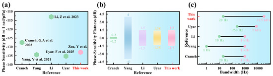
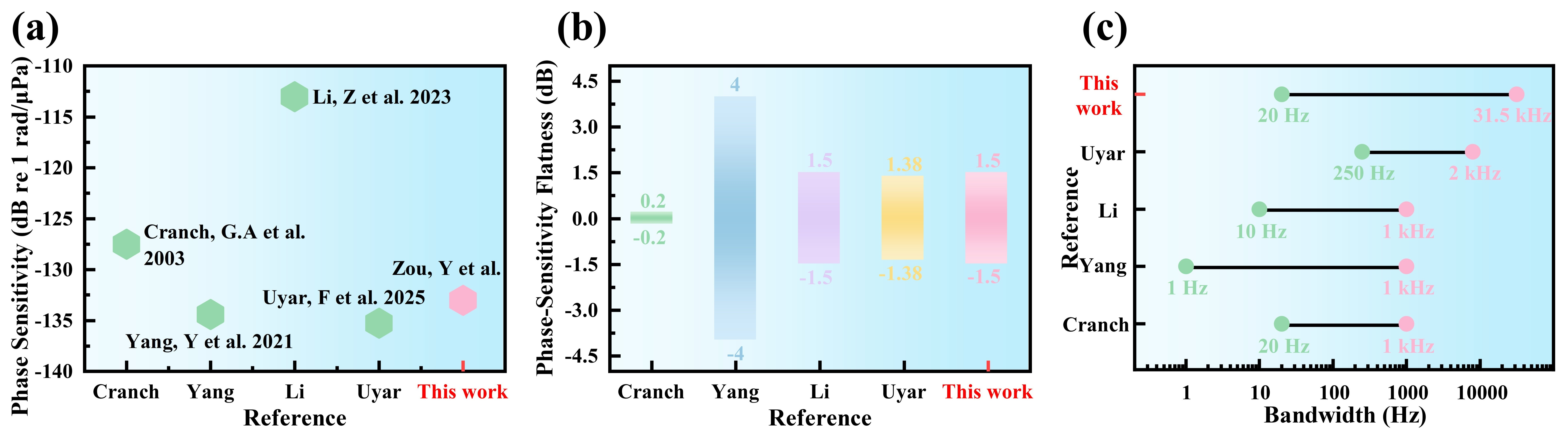
To contextualize the performance of the optimized FOH, Figure 10a–c presents a multi-metric comparison with representative broadband FOHs in the literature. Cranch et al. [24] achieved −127.5 dB re 1 rad/μPa sensitivity with ±0.2 dB flatness, but limited to 20 Hz–1 kHz. Yang et al. [25] obtained a mean sensitivity of −134.39 dB re 1 rad/μPa over 1 Hz–2 kHz using a concentric dual-tube push–pull structure. The sensitivity response fluctuated within ±3 dB from 1 Hz to 100 Hz and within ±1.5 dB from 100 Hz to 800 Hz, followed by an approximately 5 dB increase between 800 Hz and 2.2 kHz as the response approached the mechanical resonances of the two elastic tubes. Li et al. [2] achieved a substantially higher sensitivity of −113 dB re 1 rad/μPa with ±1.5 dB flatness, although its verified bandwidth was limited to 10 Hz–1 kHz. More recently, Uyar et al. [34] demonstrated −135.28 dB re 1 rad/μPa over 250 Hz–8 kHz with a maximum variation of ±1.38 dB. In contrast, the present work combines an enhanced PPSU push–pull mandrel with an internal acoustic metamaterial hollow cylinder to maintain ±1.5 dB flatness from 20 Hz to 31.5 kHz. The directivity performance further underscores the value of the metamaterial integration. At 25 kHz, the optimized FOH exhibited a horizontal directivity variation of only ±1.0 dB, leading to a significant improvement over the >5 dB peak-to-peak deviation observed in the conventional design. This uniformity is attributed to the homogenization of the acoustic impedance at the sensor–water interface by the periodic cavity structures. The directivity at 30 kHz was measured at ±1.51 dB, slightly higher than the 25 kHz result, due to residual edge diffraction effects at the upper limit of the operational band.
Figure 10.
Performance comparison of representative interferometric FOHs. (a) Mean phase sensitivity; (b) phase-sensitivity flatness; (c) operating bandwidth.
Despite these advancements, several practical considerations merit further attention before full-scale deployment. First, while the PPSU material offers excellent impedance matching and processability, its long-term stability under deep-sea hydrostatic pressures and varying temperatures remains to be verified. Second, the equivalent MDP is 27 dB re 1 μPa/√Hz above 2 kHz and 42 dB re 1 μPa/√Hz at 20 Hz, consistent with the PGC system noise floor. Future integration of closed-loop phase tracking or array-level denoising may further suppress this limit. Third, scaling to multiplexed towed arrays will necessitate evaluating element-to-element variability and potential inter-element acoustic crosstalk introduced by the periodic liner geometry.
5. Conclusions
This work demonstrates a broadband interferometric fiber-optic hydrophone targeting active and passive underwater acoustic sensing. By identifying low-order mechanical resonance and near-field scattering as the dominant bandwidth constraints, two synergistic modifications were implemented, specifically a low-impedance PPSU push–pull mandrel to elevate the mechanical resonance beyond 31.5 kHz and an internal acoustic metamaterial liner to homogenize the local pressure field and suppress cavity modes.
Experimental characterization confirms that the optimized prototype achieves an average phase sensitivity of −132 dB re 1 rad/μPa with peak-to-peak fluctuations below 3.0 dB, corresponding to plus or minus 1.5 dB about the mean, across 20 Hz to 31.5 kHz, representing a threefold bandwidth extension over conventional mandrel designs. The horizontal directivity exhibits a peak-to-peak variation of less than 2.0 dB at 25 kHz, validating effective mitigation of cylindrical scattering. Referenced to the measured phase sensitivity, the system yields a minimum detectable pressure of 27 dB re 1 μPa/√Hz above 2 kHz and 42 dB re 1 μPa/√Hz at 20 Hz, remaining over 10 dB below the deep-sea state zero noise floor.
These results substantiate that integrating polymer-based structural optimization with subwavelength acoustic liners provides a practical route to reconciling low-frequency quiet reception with broadband active sonar bandwidth requirements. The optimized architecture offers a compact and robust platform for next-generation marine exploration, seabed mapping, and autonomous underwater vehicle acoustic payloads.
Author Contributions
Conceptualization, Y.Z.; methodology, Y.Z.; software, Y.Z. and M.S.; validation, Y.Z. and M.S.; formal analysis, Y.Z. and M.S.; investigation, Y.Z. and K.L.; resources, K.L., P.X., Z.H. and M.Z.; data curation, Y.Z. and M.S.; writing—original draft preparation, Y.Z.; writing—review and editing, Y.Z. and M.S.; visualization, Y.Z. and M.S.; supervision, P.X., Z.H. and M.Z.; project administration, P.X., Z.H. and M.Z.; funding acquisition, M.Z. All authors have read and agreed to the published version of the manuscript.
Funding
This work was supported by the National Key Research and Development Program of China (2024YFCxxxx800).
Data Availability Statement
The original contributions presented in this study are included in the article. Further inquiries can be directed to the corresponding author.
Conflicts of Interest
The authors declare no conflicts of interest.
References
- Meng, Z.; Chen, W.; Wang, J.; Hu, X.; Chen, M.; Zhang, Y. Recent progress in fiber-optic hydrophones. Photonic Sens. 2021, 11, 109–122. [Google Scholar] [CrossRef] [Scilit]
- Li, Z.; Wang, C.; Gui, X.; Fu, X.; Wang, Y.; Wang, Z.; Wang, Y. A high-performance fiber-optic hydrophone for large scale arrays. J. Light. Technol. 2023, 41, 4201–4210. [Google Scholar] [CrossRef] [Scilit]
- Plotnikov, M.Y.; Lavrov, V.S.; Dmitraschenko, P.Y.; Kulikov, A.V.; Meshkovskiy, I.K. Thin cable fiber-optic hydrophone array for passive acoustic surveillance applications. IEEE Sens. J. 2019, 19, 3376–3382. [Google Scholar] [CrossRef] [Scilit]
- Liu, Y.; Cheng, L.; Zou, Y.; Hu, Z. Thin fiber-optic hydrophone towed array for autonomous underwater vehicle. IEEE Sens. J. 2024, 24, 15125–15132. [Google Scholar] [CrossRef] [Scilit]
- Duarte, C.M.; Chapuis, L.; Collin, S.P.; Costa, D.P.; Devassy, R.P.; Eguiluz, V.M.; Erbe, C.; Gordon, T.A.C.; Halpern, B.S.; Harding, H.R.; et al. The soundscape of the anthropocene ocean. Science 2021, 371, eaba4658. [Google Scholar] [CrossRef] [Scilit] [PubMed]
- Van Parijs, S.; Clark, C.; Sousa-Lima, R.; Parks, S.; Rankin, S.; Risch, D.; Van Opzeeland, I. Management and research applications of real-time and archival passive acoustic sensors over varying temporal and spatial scales. Mar. Ecol. Prog. Ser. 2009, 395, 21–36. [Google Scholar] [CrossRef] [Scilit]
- Mooney, T.A.; Di Iorio, L.; Lammers, M.; Lin, T.-H.; Nedelec, S.L.; Parsons, M.; Radford, C.; Urban, E.; Stanley, J. Listening forward: Approaching marine biodiversity assessments using acoustic methods. R. Soc. Open Sci. 2020, 7, 201287. [Google Scholar] [CrossRef] [Scilit] [PubMed]
- Fenta, M.C.; Potter, D.K.; Szanyi, J. Fibre optic methods of prospecting: A comprehensive and modern branch of geophysics. Surv. Geophys. 2021, 42, 551–584. [Google Scholar] [CrossRef] [Scilit]
- Williams, E.F.; Fernández-Ruiz, M.R.; Magalhaes, R.; Vanthillo, R.; Zhan, Z.; González-Herráez, M.; Martins, H.F. Distributed sensing of microseisms and teleseisms with submarine dark fibers. Nat. Commun. 2019, 10, 5778. [Google Scholar] [CrossRef] [Scilit] [PubMed]
- Zhan, Z. Distributed acoustic sensing turns fiber-optic cables into sensitive seismic antennas. Seismol. Res. Lett. 2020, 91, 1–15. [Google Scholar] [CrossRef] [Scilit]
- Guardato, S.; Riccio, R.; Janneh, M.; Bruno, F.A.; Pisco, M.; Cusano, A.; Iannaccone, G. An innovative fiber-optic hydrophone for seismology: Testing detection capacity for very low-energy earthquakes. Sensors 2023, 23, 3374. [Google Scholar] [CrossRef] [Scilit] [PubMed]
- Wu, S.; Huang, J.; Pang, Y.; Wang, J.; Gu, H. Direction-finding study of a 1.7 mm diameter towed hydrophone array based on UWFBG. Sensors 2024, 24, 4300. [Google Scholar] [CrossRef] [Scilit] [PubMed]
- Li, W.; Chen, Y.; Liang, Y.; Lu, Y.; Meng, Z. Directivity dependence of a distributed fiber optic hydrophone on array structure. Sensors 2022, 22, 6297. [Google Scholar] [CrossRef] [Scilit] [PubMed]
- Cranch, G.A.; Nash, P.J. High-responsivity fiber-optic flexural disk accelerometers. J. Light. Technol. 2000, 18, 1233–1243. [Google Scholar] [CrossRef] [Scilit]
- Foster, S.; Tikhomirov, A.; Van Velzen, J. Towards a high performance fiber laser hydrophone. J. Light. Technol. 2011, 29, 1335–1342. [Google Scholar] [CrossRef] [Scilit]
- Azmi, A.I.; Sen, D.; Peng, G.-D. Sensitivity enhancement in composite cavity fiber laser hydrophone. J. Light. Technol. 2010, 28, 1844–1850. [Google Scholar] [CrossRef] [Scilit]
- Cranch, G.A.; Nash, P.J. Large-scale multiplexing of interferometric fiber-optic sensors using TDM and DWDM. J. Light. Technol. 2001, 19, 687–699. [Google Scholar] [CrossRef] [Scilit]
- Liao, Y.; Austin, E.; Nash, P.J.; Kingsley, S.A.; Richardson, D.J. Highly scalable amplified hybrid TDM/DWDM array architecture for interferometric fiber-optic sensor systems. J. Light. Technol. 2013, 31, 882–888. [Google Scholar] [CrossRef] [Scilit]
- Denisov, A.; Soto, M.A.; Thévenaz, L. Going beyond 1,000,000 resolved points in a brillouin distributed fiber sensor: Theoretical analysis and experimental demonstration. Light. Sci. Appl. 2016, 5, e16074. [Google Scholar] [CrossRef] [Scilit] [PubMed]
- Akkaya, O.C.; Digonnet, M.J.F.; Kino, G.S.; Solgaard, O. Time-division-multiplexed interferometric sensor arrays. J. Light. Technol. 2013, 31, 2701–2708. [Google Scholar] [CrossRef] [Scilit]
- Wang, J.; Gu, H.; Wang, P.; Yao, G.; Huang, J.; Liu, W.; Xu, D.; Wu, S. Equivalent self-noise suppression of distributed hydroacoustic sensing system using SDM signals based on multi-core fiber. Sensors 2025, 25, 4877. [Google Scholar] [CrossRef] [Scilit] [PubMed]
- Wang, W.; Hu, Q.; Ma, L.; Shang, F.; Leng, H.; Song, J. Optimal coherence length control in interferometric fiber optic hydrophones via PRBS modulation: Theory and experiment. Sensors 2025, 25, 4711. [Google Scholar] [CrossRef] [Scilit] [PubMed]
- Bucaro, J.A.; Dardy, H.D.; Carome, E.F. Fiber-optic hydrophone. J. Acoust. Soc. Am. 1977, 62, 1302–1304. [Google Scholar] [CrossRef] [Scilit]
- Cranch, G.A.; Nash, P.J.; Kirkendall, C.K. Large-scale remotely interrogated arrays of fiber-optic interferometric sensors for underwater acoustic applications. IEEE Sens. J. 2003, 3, 19–30. [Google Scholar] [CrossRef] [Scilit]
- Yang, Y.; Luo, Z.; Wang, Z.; Zhang, Y.; Chang, T.; Yu, M.; Cheng, L.; Wu, C.; Cui, H.-L. High-performance fiber optic interferometric hydrophone based on push–pull structure. IEEE Trans. Instrum. Meas. 2021, 70, 9511313. [Google Scholar] [CrossRef] [Scilit]
- Birri, A.; McCary, K.; Wilson, B.A.; Blue, T.E. Thermally induced bend loss of silica optical fiber. IEEE Sens. J. 2018, 18, 6181–6187. [Google Scholar] [CrossRef] [Scilit]
- Savovic, S.; Kovacevic, M.S.; Bajic, J.S.; Stupar, D.Z.; Djordjevich, A.; Živanov, M. Temperature dependence of mode coupling in low-NA plastic optical fibers. J. Light. Technol. 2015, 33, 89–94. [Google Scholar] [CrossRef] [Scilit]
- Wang, C.; Li, S.-D.; Zheng, W.-G.; Huang, Q.-B. Acoustic absorption characteristics of new underwater omnidirectional absorber. Chin. Phys. Lett. 2019, 36, 044301. [Google Scholar] [CrossRef] [Scilit]
- Cummer, S.A.; Christensen, J.; Alù, A. Controlling sound with acoustic metamaterials. Nat. Rev. Mater. 2016, 1, 16001. [Google Scholar] [CrossRef] [Scilit]
- Ma, G.; Sheng, P. Acoustic metamaterials: From local resonances to broad horizons. Sci. Adv. 2016, 2, e1501595. [Google Scholar] [CrossRef] [Scilit] [PubMed]
- Deane, G.B. The wenz curves for underwater ambient sound. J. Acoust. Soc. Am. 1962, 157, 9–10. [Google Scholar]
- Im, J.; Roh, Y. A finite element analysis of an interferometric optical fiber hydrophone. J. Acoust. Soc. Am. 1998, 103, 2425–2431. [Google Scholar] [CrossRef] [Scilit]
- Im, J.; Roh, Y. A finite element analysis of an interferometric optical fiber hydrophone with a concentric composite mandrel including a foaming layer. J. Acoust. Soc. Am. 1999, 106, 1363–1368. [Google Scholar] [CrossRef] [Scilit]
- Uyar, F.; Safa Aldemir, A.; Kartaloğlu, T.; Özbay, E.; Özdür, I. A compliant mandrel-based fiber-optic hydrophone for underwater acoustic sensing. IEEE Sens. J. 2025, 25, 34671–34680. [Google Scholar] [CrossRef] [Scilit]

Disclaimer/Publisher’s Note: The statements, opinions and data contained in all publications are solely those of the individual author(s) and contributor(s) and not of MDPI and/or the editor(s). MDPI and/or the editor(s) disclaim responsibility for any injury to people or property resulting from any ideas, methods, instructions or products referred to in the content. |
© 2026 by the authors. Licensee MDPI, Basel, Switzerland. This article is an open access article distributed under the terms and conditions of the Creative Commons Attribution (CC BY) license.