


Abstract
We demonstrate a high-power broadband continuous mode-hop-free (MHF) tunable singly resonant optical parametric oscillator (SRO). To obtain broadband continuous MHF operation, a synchronous etalon-angle locking technique and a feedback-optimized temperature controller were developed based on theoretical investigation. At a pump power of 21 W that was eight times the pump threshold, the measured signal was tuned from 1551.9087 nm to 1568.6549 nm, and the corresponding idler was tuned from 3384.3030 nm to 3307.3073 nm simultaneously. A continuous MHF tuning bandwidth of 2.064 THz was achieved at a tuning speed of 4.7 GHz/s. Continuous MHF operation in the whole tuning band was verified by high-resolution absorption spectroscopy of acetylene and methane, and by the continuous sinusoidal transmission through a Fabry–Perot etalon. The measured powers of the signal at 1560 nm and idler at 3346 nm were 4.12 W and 2.26 W with peak-to-peak fluctuations of ±0.42% and ±0.18%, respectively. These results represent, to the best of our knowledge, the widest continuous MHF tuning bandwidth achieved by a temperature-tuned SRO at high pump power, providing a high-power dual-band coherent source for precision spectroscopy.
1. Introduction
Continuous-wave (cw) narrow-linewidth lasers with broad tuning bands around 1.5 μm and 3 μm are in high demand for gas sensing and tracing, atmospheric monitoring, precision spectroscopy and so on [1,2,3,4]. These bands host the characteristic absorption features of key atmospheric and toxic gases, including ozone (O3), methane (CH4), carbon monoxide (CO), ammonia (NH3), acetylene (C2H2), hexane (C6H14), and hydrogen cyanide (HCN). For such applications, continuous mode-hop-free (MHF) frequency tuning over several hundred GHz to THz is often required to cover multiple absorption lines in a single scan.
A well-established approach to generating coherent radiation in these bands is a cw singly resonant optical parametric oscillator (SRO) pumped by a cw single-longitudinal-mode (SLM) 1 μm laser [5,6,7,8,9]. However, achieving continuous mode-hop-free (MHF) tuning over a broad bandwidth remains challenging. Mode hops in an SRO can arise from two distinct sources. The first is external perturbations including pump frequency jitter, mechanical vibration, thermal drift, and air turbulence, which shift the cavity resonance relative to the parametric gain peak [10,11]. These perturbations can be mitigated by environmental shielding and active stabilization. The second limitation is intrinsic modulation instability (MI). When the pump power significantly exceeds the oscillation threshold, spontaneous parametric amplification of cavity sidebands can trigger mode hops even in the absence of external disturbances [12]. This mechanism imposes an upper bound on the MHF tuning bandwidth at high pump powers.
Several methods have been proposed to extend the MHF tuning range. The most extensively studied approach is pump frequency tuning, which offers the advantages of easy operation, relatively wide tuning band and considerable tuning speed. M. van Herpen et al. demonstrated continuous tuning of a non-resonant idler within a 12 GHz range with a maximum output of 0.7 W using a tunable SLM pump source [10]. X. P. Hong et al. further extended the MHF tuning range of the idler to 900 GHz with a maximum output of 0.9 W by incorporating synchronized temperature control of nonlinear crystal [11]. J. Courtois et al. achieved 2.25 THz MHF idler tuning with a maximum output of 0.5 W using a tunable extended-cavity diode laser (ECDL) as a pump [13]. Despite these advances, pump tuning has the inherent limitation that only the non-resonant idler is tunable, while the signal frequency remains constrained by the cavity. Moreover, the MHF bandwidth and output power are ultimately bound by the performance of the pump source. An alternative approach is cavity-length tuning via a movable cavity mirror mounted on a piezoelectric transducer (PZT). U. Strößner et al. demonstrated an optical parametric oscillator (OPO) with 38 GHz MHF tuning range and 0.25 GHz/s tuning speed with a maximum output of 0.8 W by changing the cavity length and synchronously tilting the etalon via a feedback loop [14]. Alternatively, the method of the nonlinear crystal temperature tuning offers the largest tuning range of OPO while both the signal and idler can be tuned simultaneously [8,12,15]. However, when the pump power is significantly above the threshold, the nonlinear gain of the SRO intensifies, and the intrinsic MI becomes pronounced. Sideband modes amplified through three-wave coupling experience net roundtrip gain even with the intracavity etalon being employed, causing frequent mode hops that disrupt continuous MHF tuning [12]. L. M. Hu et al. proposed a passive stabilization technique that only suppress mode hops in SRO at a few fixed operating points [16]. A distinct approach to circumventing mode hops is the scan-and-stitch technique, in which a wavelength meter detects discontinuities in real time and the control software rescans the interrupted segments [17]. Nevertheless, this method does not eliminate mode hops. To date, THz-level broadband MHF temperature tuning of an SRO at pump levels several times the threshold has not been demonstrated.
In this paper, we present a broadband continuous MHF tunable SRO based on magnesium-oxide-doped periodically poled lithium niobate (MgO:PPLN) operating at high pump powers. The intrinsic MI that limits MHF tuning operation at high pump power is analyzed theoretically, providing the condition for broadband continuous MHF tuning of SRO using a synchronously tuned intracavity etalon. The effective thermo-optic path-length coefficient of the MgO:PPLN crystal is measured and the result indicates that synchronization between the cavity resonance and the parametric gain peak frequencies can be realized by feedback controlling the cavity length. On this basis, a program-controlled temperature controller and a synchronous etalon-angle locking system are developed and employed to construct a broadband continuous MHF tunable SRO, and the characteristics of the SRO are investigated.
2. Theoretical Analysis
In a temperature-tuned SRO, when the pump power exceeds the instability threshold (i.e., the pump power above which MI occurs), the signal sidebands in certain frequency offsets will experience net parametric gain surpassing the cavity loss through the three-wave interaction inside the nonlinear crystal. These sidebands are then amplified from quantum noise, competing with the carrier for gain and eventually causing multimode oscillation and mode hops. Since the pump is involved in the amplification of the signal sideband, and the total parametric gain is shared between the carrier and the amplified sidebands, the carrier gain is correspondingly depleted. Consequently, whether or not a mode-hop event will take place can be estimated by analyzing the single-pass-gain parameter of the signal sideband normalized to the cavity loss (Gsp).
Note that the following analysis is conducted under the premise that the cavity resonance modes follow the varying signal frequency during temperature tuning. This premise is experimentally verified in Section 4 and the Supplementary Materials using a Mach–Zehnder interferometer. The effective thermo-optic path-length coefficient of the MgO:PPLN crystal governing the cavity resonance behavior passively tracks the frequency shift required by the phase-matching condition, and the residual deviation is compensated by a feedback loop on the PZT.
Gsp is defined as
where δ is the effective roundtrip power loss of the whole cavity at the signal wavelength, Ω is the frequency detuning of the sideband from the carrier frequency of the signal, and ζΦ,rt is the largest eigenvalue of Φrt, which is the transfer matrix of the signal during a roundtrip inside the cavity.
Since the spontaneous parametric emission exists at all sideband frequencies, the absence of mode hop of SRO can be concluded only when the condition of Gsp(Ω) ≤ 0 is met over the whole sideband frequency range. To get Gsp(Ω) of the SRO with signal resonated in the cavity, the influences of three-wave nonlinear interaction on signal sidebands should be investigated firstly by solving the coupled wave functions of SRO. Using the definition of normalized amplitudes Aj for the three interaction fields, j = (i, s, p), where Aj are the sums of the normalized carrier amplitudes Aj(0) defined based on |Ap(0)(z = 0)|2 = 1 and the normalized sideband amplitudes aj(t,z), the coupled wave equations in the frequency domain for the sidebands of SRO can be written as [12]
where ᾶj± are the amplitudes of the sideband of field j in the frequency domain, Kj,±(z, Ω) = ±[n(ωj ± Ω)(ωj ± Ω) − njωj]/c − Ω/vref ± [−(ωpnp − ωsns − ωini)/c + 2π/Λ], ωj is the carrier frequency of field j, n(ω) is the refractive index of the nonlinear crystal at the frequency of ω calculated from the full Sellmeier equation of MgO:PPLN, so that Kj,± implicitly includes the group-velocity dispersion (GVD) via the exact frequency dependence of the refractive index [18], nj is the refractive index of the nonlinear crystal at ωj, vref is the reference group velocity at 1560 nm, c is light speed in the vacuum, Λ is the poling period of MgO:PPLN crystal, and g represents the parametric gain coefficient of SRO defined as
where deff is the effective nonlinear coefficient of MgO:PPLN, Pp is the pump power, Sp is the cross-sectional area of the pump beam, and ε0 is the permittivity of the vacuum. In the case of perfect phase matching, the threshold gain coefficient of SRO (gt) satisfies
where l is the length of the nonlinear crystal.
Assuming that the signal is perfectly resonated in the cavity, the normalized carrier amplitudes Aj(0) can be approximated as
where the initial value (at z = 0) of Ap(0) is assumed to be 1, and that of As(0) can be obtained by the relation
Using Equations (1)–(6), the vector (ῦ) formed by the 6 sidebands (ᾶj±)—that is, the second matrix of the right side in Equation (2) at different positions (z) and different nonlinear crystal temperatures (T)—can be calculated by the Runge–Kutta method. Furthermore, a 6 × 6 transfer matrix (Φ(l,0)) defined by ῦ(l) = Φ(l,0)ῦ(0) can be obtained at a certain value of T. The actual value of T, i.e., the temperature of the nonlinear crystal in the pump region, can be approximately estimated using an empirical formula as [19]
where T0 is the boundary temperature of the nonlinear crystal that can be precisely controlled using a temperature controller, and Psc is the intracavity signal power that can be approximately simulated as (0.222 × Pp − 0.667)/0.015 according to our experimental results.
After numerically integrating over the crystal length to obtain the full 6 × 6 transfer matrix Φ(l,0), a 2 × 2 matrix (Φs) that only relates to ᾶs± can be extracted. This extraction is legitimate because the idler and pump sideband contributions have already been incorporated during the integration step.
For the suppression of mode hop, we introduce an intracavity etalon that provides frequency-dependent loss to the sidebands while remaining transparent at the signal carrier frequency. When a lithium niobate (LN) etalon is used, the roundtrip transfer matrix of the signal (Φrt) inside the cavity incorporates the single-pass crystal transfer matrix (Φs), the linear cavity phase delay (φ), and the etalon transmission function Ũ(ω):
where φ = (ωsL + ωpnpl − ωinil)/c − 2πl/Λ, L = 415 mm is the length of the cavity except for the nonlinear crystal, and ũ(Ω) is the normalized transfer function defined as Ũ(ωs + Ω)/Ũ(ωs). Ũ(ω) can be written as
where neta and Leta are the refractive index and thickness of LN etalon, respectively. θ is the internal angle between the etalon normal and the beam propagation direction.
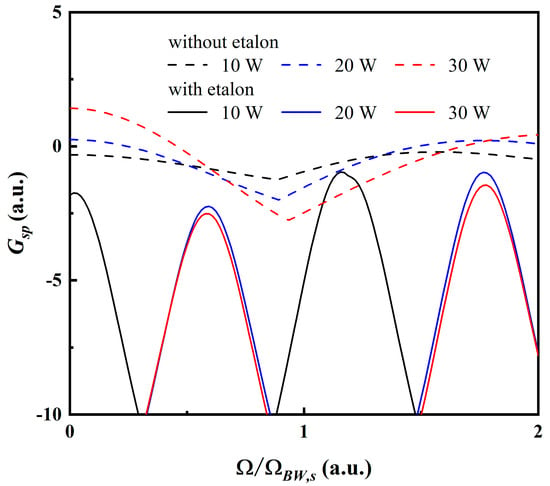
Using Equations (1)–(10), the Sellmeier equation of MgO:PPLN crystal with a dope concentration of 5 at.% presented in [18] and that of LN crystal presented in [20], and experimental parameters of Λ = 30.6 μm, deff = 1.65 × 10⁻¹¹ mV−1, T0 = 70 °C, Sp = 346 μm2, l = 30 mm, δ = 0.03 and Leta = 0.3 mm, the normalized single-pass-gain parameter (Gsp) as a function of the normalized frequency detuning of the sideband from the carrier frequency of the signal (Ω/ΩBW,s) can be numerically calculated at different pump powers (pump wavelength: 1064 nm), as shown in Figure 1. ΩBW,s = π/Lδvis is the parametric gain bandwidth for signal, and δvis is the group velocity mismatch between idler and signal.
Figure 1.
Normalized single-pass-gain parameter as a function of the normalized frequency detuning of the sideband from the carrier frequency of the signal.
When the intracavity LN etalon is not used, Gsp at Pp = 10 W can be maintained below 0 for all Ω (black dashed curve in Figure 1), while the pump power is 3.7 times higher than the threshold power of 2.65 W calculated using Equation (4). At Pp = 20 W (red dashed curve) and Pp = 30 W (blue dashed curve), Gsp is above 0 at sideband frequencies where Ω/ΩBW,s is near 0 or exceeds 1.6. This means that at these pump levels, MI-driven mode hops will occur.
The red solid curve in Figure 1 is the spectrum of Gsp when a LN etalon is inserted into the cavity with θ = 5.97° at Pp = 20 W. Over the range of Ω/ΩBW,s from 0 to 2, Gsp is below 0, meaning that the mode hop can be eliminated using an intracavity etalon and the SRO is in MHF operation. In the case of Pp = 30 W with the etalon angle set as 5.97°, the mode hop can also be suppressed, as shown by the blue solid curve in Figure 1.
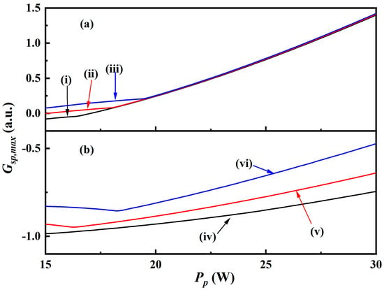
To investigate the influences of pump power and temperature of MgO:PPLN crystal on the presence of the mode-hop event, the evolution of the maximum value of the normalized single-pass-gain parameter (Gsp,max) was calculated, as shown in Figure 2. The curves in Figure 2a indicate the simulated Gsp,max for the SRO without the etalon in the cavity as a function of Pp at different boundary temperatures of MgO:PPLN, which are 30 °C (curve (i)), 50 °C (curve (ii)) and 70 °C (curve (iii)). It can be seen that Gsp,max increases monotonically with increasing Pp or increasing T0. For the cases that T0 = 30 °C, T0 = 50 °C and T0 = 70 °C, the critical pump powers (Pc) at which the mode-hop events take place are 17.2 W, 15.2 W and <15 W, respectively. Without intracavity etalon, the SRO cannot maintain MHF operation across the temperature tuning range from 30 °C to 70 °C at a pump power of 21 W.
Figure 2.
Simulated Gsp,max for the SRO without (a) and with (b) the etalon in the cavity as a function of Pp at T0. Curves (i), (ii) and (iii): T0 = 30 °C, T0 = 50 °C, and T0 = 70 °C without the etalon. Curves (iv), (v) and (vi): T0 = 30 °C and θ = 9°, T0 = 50 °C and θ = 11.3°, and T0 = 70 °C and θ = 13.9°.
When an etalon is inserted into the cavity, and the etalon angle is synchronously adjusted so that its transmission peak tracks the moving carrier during temperature tuning while maintaining adequate sideband suppression, the simulated curves of Gsp,max corresponding to the optimal etalon angle as a function of Pp at different T0 are shown in Figure 2b. The curves (iv), (v) and (vi) in Figure 2b indicate Gsp,max as a function of Pp at T0 = 30 °C and θ = 9°, T0 = 50 °C and θ = 11.3°, and T0 = 70 °C and θ = 13.9°, respectively. In these three cases, Pc values are all beyond 30 W.
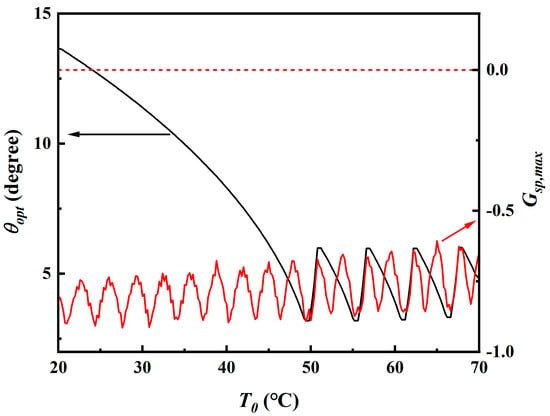
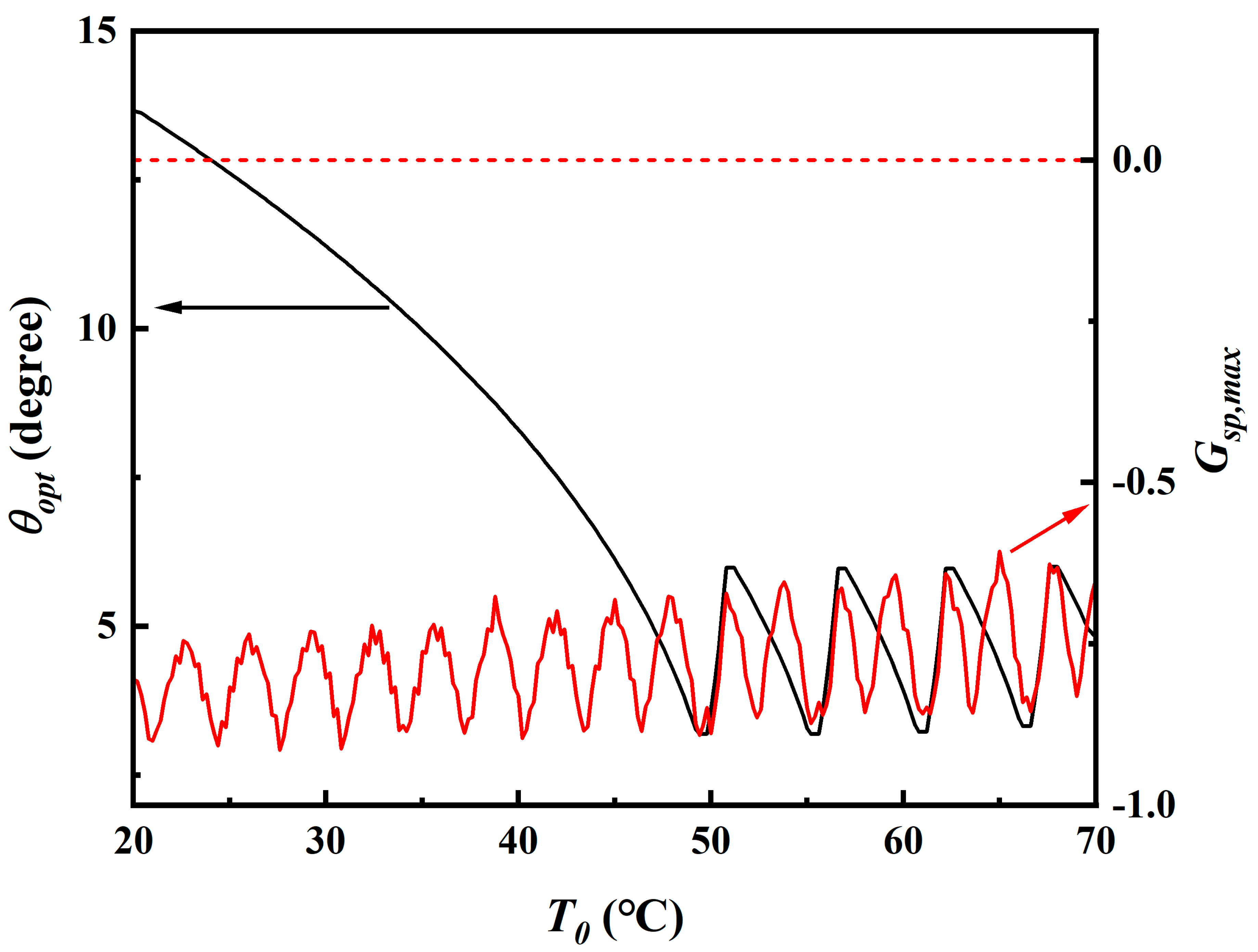
The value of θ is a crucial parameter for mode-hop suppression when the SRO is continuously temperature-tuned at a high pump power. There exists an optimum value of θ (θopt) to balance the requirement of nonpositive value of Gsp,max and the continuity of angle adjustment. The black curve in Figure 3 shows the simulated θopt as a function of T0 at a pump power of 21 W calculated using a greedy nearest neighbor algorithm. It can be seen that with increasing T0, the value of θopt is monotonously reduced from 13.7° to 3.2° over 20 °C ≤ T ≤49.4 °C, and periodically varies with the angle variation range from 3.2° to 6.0° and the temperature period of approximate 11.4 °C over 49.4 °C ≤ T ≤ 70 °C. The red curve shows the Gsp,max corresponding to the θopt as a function of T0. Over the region of 20 °C ≤ T ≤ 70 °C, Gsp,max remains below 0. Consequently, cw MHF operation of SRO at a pump power of 21 W can be realized with the help of an intracavity etalon when the temperature of MgO:PPLN crystal is tuned from 20 °C to 70 °C.
Figure 3.
Simulated θopt and Gsp,max as a function of T0 at the pump power of 21 W. Red dashed line: Gsp,max = 0.
3. Experimental Setup
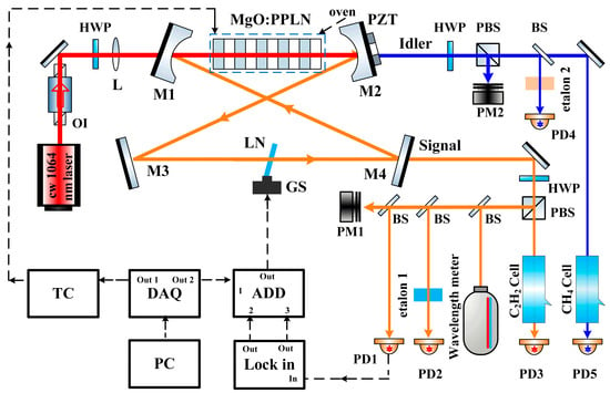
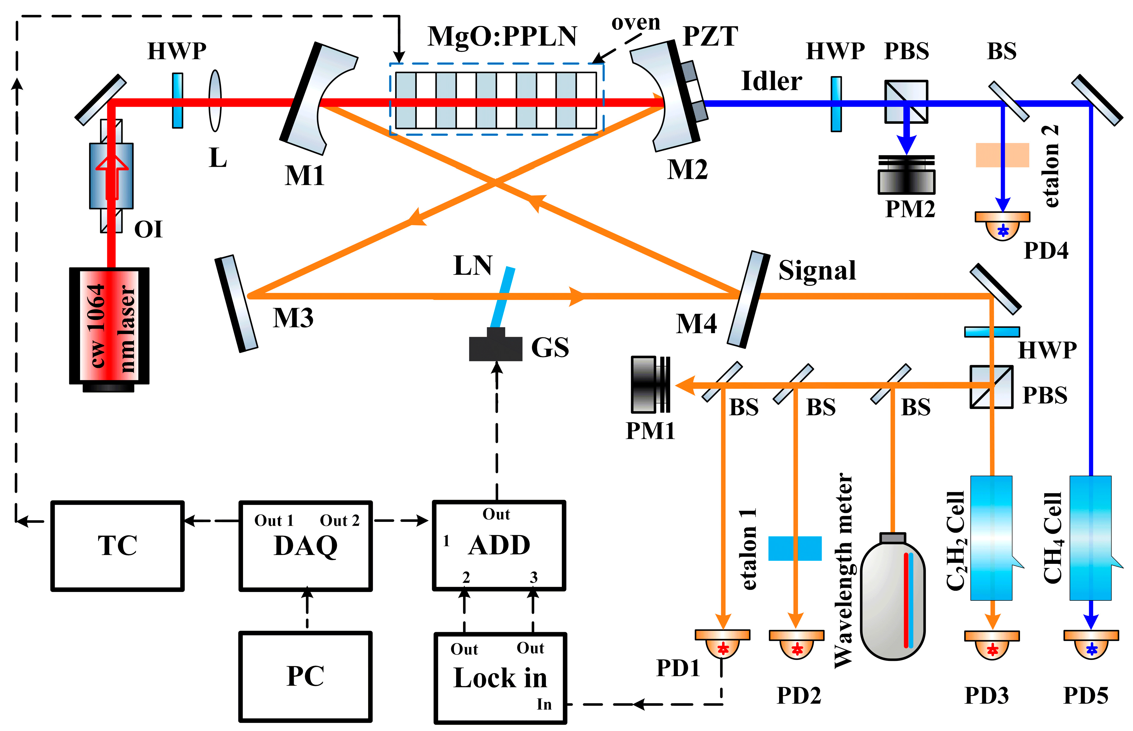
The experimental setup of the continuous MHF tunable cw SRO is shown in Figure 4. The SRO was pumped by a home-made MHF cw SLM 1064 nm laser with a maximum output of 30 W (detailed information is provided in the Supplementary Materials). A MgO:PPLN crystal (Gooch & Housego Inc., llminster, UK) with a length of 30 mm and a poling period of 30.6 μm was chosen as the nonlinear material in the SRO. To eliminate the etalon effect, the end faces of the MgO:PPLN crystal were anti-reflection-coated at the pump, signal and idler (R1064nm < 2%, R1.5μm < 0.5%, R3.3μm < 1%). For temperature tuning and stable parametric downconversion, the crystal was mounted in a copper oven, which was temperature-controlled by a home-made program-controlled temperature controller with an accuracy better than 0.002 °C. To prevent extra nonlinear processes, a singly resonated ring-cavity composed of two concave mirrors and two plane mirrors was designed and fabricated. The concave mirrors M1 and M2 with a radius of curvature of 100 mm were high-transmission (HT)-coated for pump and idler (T1064nm&3.3μm > 95%) and high-reflection (HR)-coated for signal (R1.5μm > 99.8%). M2 was attached to a PZT, which was used to continuously control the length of cavity. The plane mirror M3 was HR-coated for signal (R1.5μm > 99.8%). The plane mirror M4 was partial-transmission-coated for signal (T1.5μm = 1.5%). In order to realize continuous MHF tuning operation, an optical polished 0.3 mm thick LN crystal was inserted as the intracavity etalon. A scanner (GS, 6220HM40BR Cambridge Technology, Bedford, MA, USA) with a speed of 1°/ms and a voltage response of 1°/V was used to control the angle of the etalon. A direct current (DC) signal generated via a data acquisition device (DAQ, NI PCIe-6376, National instruments, Austin, TX, USA) program-controlled by a computer, a modulation signal from a lock-in amplifier (LIA, SR830, Stanford Research System, Sunnyvale, CA, USA), and an error signal generated by the LIA and a home-made proportional–integral amplifier (PIA) were applied to the GS by a home-made adder (ADD) for synchronous tuning and locking of the angle of the etalon. The power of the main part of the signal from the SRO was measured and recorded by a power meter (PM1, LabMax-Top, Coherent, Santa Clara, CA, USA). The signal from a photodiode (PD1) illuminated by a small part of the signal was injected into the LIA and used to generate the error signal. A Fabry–Perot interferometer (F-P, free spectral range: 375 MHz, fineness: 375) was utilized to generate the signal detected by PD2, which provided the relative frequency shift of the resonant mode of the SRO cavity. Another small part of the signal was used to study the tuning behavior of signal with the help of a wavelength meter (WS6-771, HighFinesse, Tuebingen, Germany). The fourth small part of the signal was used to examine the mode-hop event of signal with the help of an F-P etalon (etalon1); the residual part of the signal was injected into an acetylene (C2H2) gas cell for verifying the MHF tuning of signal and correcting the wavelength. The power of the main part of the idler from the SRO was measured and recorded by PM2. A small part of the idler was injected into a methane (CH4) gas cell for verifying the MHF tuning of idler, and another small part of the idler was used to examine the mode-hop event of the idler using an F-P etalon (etalon2).
Figure 4.
Experimental setup of the cw MHF SRO. OI: optical isolator; HWP: half wave plate; L: lens; PZT: piezoelectric transducer; PBS: polarizing beam splitter; BS: beam splitter; PM1, PM2: power meter; PD1, PD2, PD3, PD4: photodetector @ 1.4–1.6 μm; PD5, : photodetector @ 3–3.4 μm; GS: galvanometer scanner; DAQ: data acquisition device; TC: temperature controller; ADD: adder; Lock-in: lock-in system; PC: computer.
4. Experimental Results and Discussion
To achieve continuous MHF tuning, the cavity resonance modes should be maintained synchronous with the peak parametric gain during temperature tuning. The cavity resonance frequency is governed by two contributions, namely the thermal expansion of the MgO:PPLN crystal providing passive tuning, and the feedback control based on the PZT providing active correction.
The effective thermo-optic path-length coefficient (ETPC) of the MgO:PPLN crystal was measured using a Mach–Zehnder interferometer (MZI) with the nonlinear crystal placed in one arm and the crystal temperature precisely controlled (see Supplementary Materials for details) [18,21]. The measured ETPC of the MgO:PPLN crystal increases monotonically from approximately 74.75 × 10⁻⁶ K−1 at 20 °C to 79.60 × 10⁻⁶ K−1 at 70 °C (see Figure S4). Using this data, the cavity resonance shift induced by thermal expansion was calculated and compared with the signal frequency shift required by the phase-matching condition. The result confirms that the thermal expansion of the MgO:PPLN crystal shifts the cavity resonance frequency by an amount closely matching the phase-matching-induced signal frequency shift over the 20–70 °C range. Consequently, the cavity resonance passively tracks the parametric gain peak during temperature tuning, with only a small residual deviation that is compensated by a feedback loop adjusting the PZT on M2 based on the readouts of the wavelength meter and PD2.
In order to prevent the mode hop induced by the temperature fluctuation of the nonlinear crystal during the temperature tuning process, and realize continuous broad temperature tuning of SRO with a tuning speed as high as possible, a temperature control system for MgO:PPLN was designed and optimized. The temperature control system comprised a digital temperature setting unit, a temperature monitoring unit based on a thermistor, a feedback unit composed of an instrumentation amplifier, a proportional–integral–differential (PID) amplifier and a common-collector amplifier, as well as a thermoelectric cooler (TEC) as the heat transfer element. By optimizing the PID amplifier, rapid temperature ramping of the crystal oven was realized.
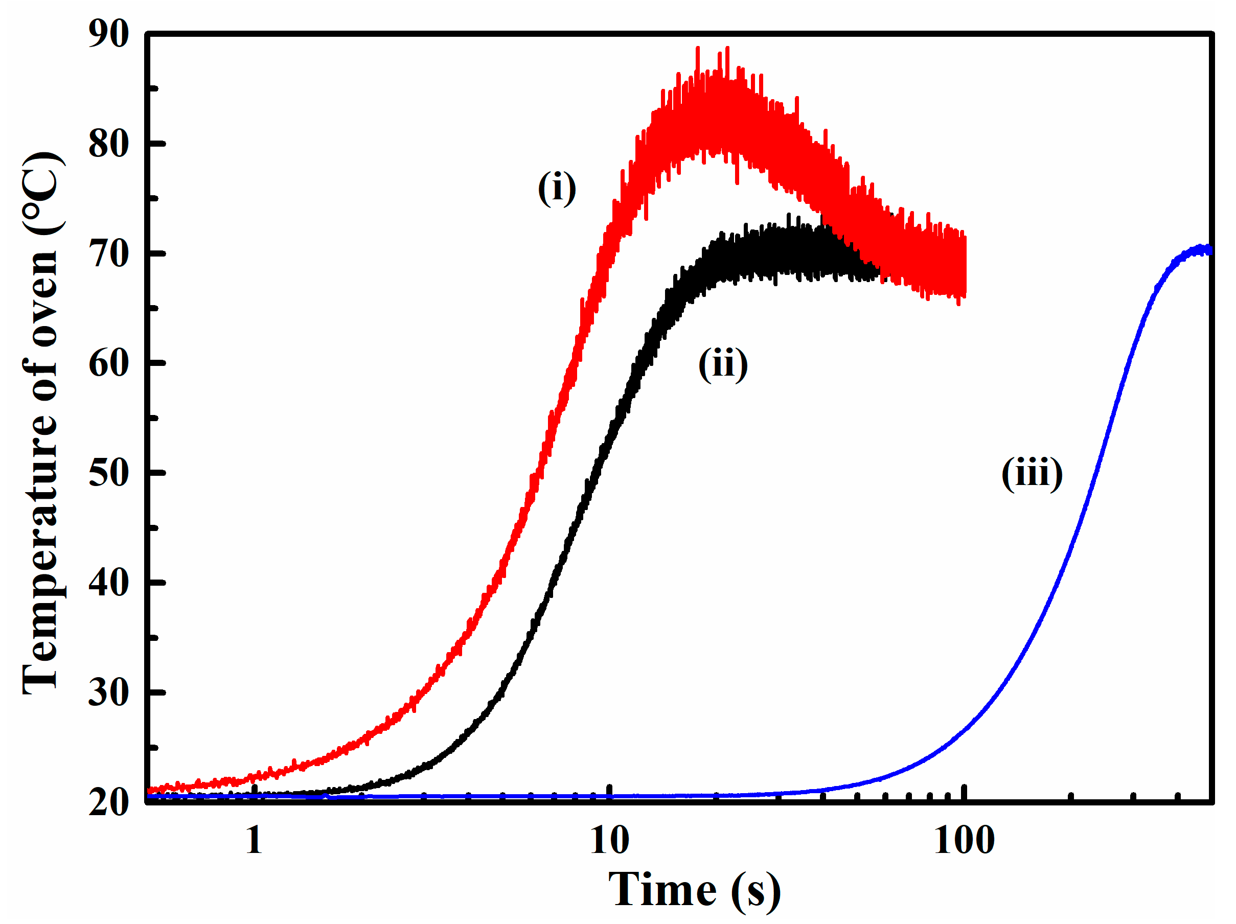
When the setting temperature (Ts) was directly set as 70 °C, the actual temperature rose sharply to 70 °C in only 9.5 s, as shown by curve (i) in Figure 5, but a significant overshoot occurred and the peak–peak temperature fluctuation was 0.85 °C for a given time duration of 0.05 s near 70 °C. This temperature fluctuation is far beyond 0.1 °C, which is the maximum tolerated temperature variation for an SRO in continuous MHF tuning. To overcome this problem, a digital temperature setting unit was implemented, in which the voltage signal corresponding to the setting temperature was generated via a LabVIEW program and the DAQ card, replacing the original analog unit. When Ts was ramped from 20 °C to 70 °C gradually with a constant step of 0.1 °C in every time interval of 0.04 s, as shown by curve (ii) in Figure 5, the overshoot disappeared but the peak-to-peak temperature fluctuation was 0.82 °C for a given time duration of 0.05 s around the monitored temperature of 70 °C. To further suppress the temperature fluctuation, the step size of Ts was dynamically adjusted by a feedback unit embedded in the program. With this optimized algorithm, the temperature ramp from 20 °C to 70 °C required approximately 400 s (the temperature tuning speed is 0.12 °C/s), and the measured peak-to-peak short-term temperature fluctuation over a time period of 0.05 s was reduced to less than 0.1 °C around the monitored temperature of 70 °C, as shown by curve (iii). Such a fluctuation level is sufficiently low to avoid the mode hops of SRO caused by temperature fluctuation during the tuning process.
Figure 5.
Measured temperature of the crystal oven as a function of time using the program-controlled temperature controller. (i) Ts was directly set as 70 °C; (ii) Ts was increased gradually with a constant step of 0.1 °C in every time interval of 0.04 s; (iii) Ts was increased gradually with a nonlinear varied step controlled by a feedback unit.
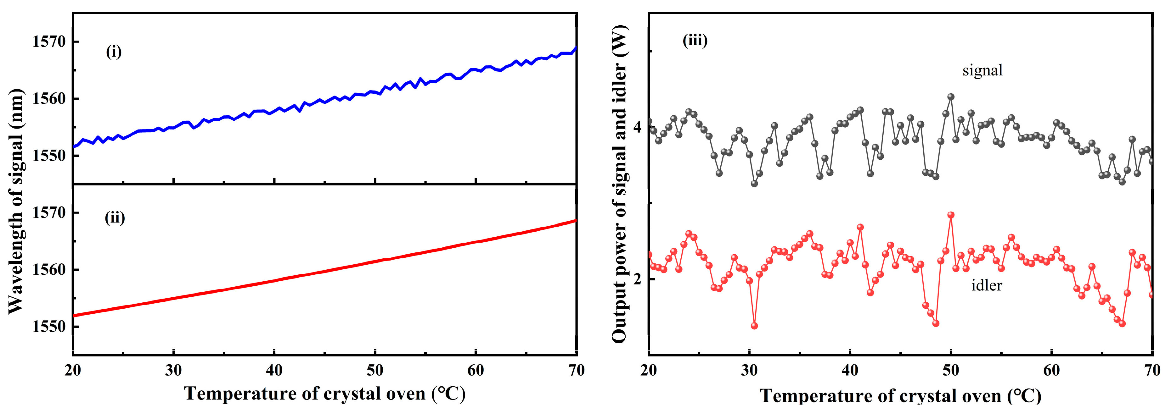
Using the program-controlled temperature controller, the tuning behavior of the MgO:PPLN-based SRO was investigated at a pump power of 21 W. Curve (i) in Figure 6 shows the signal wavelength as a function of crystal temperature when the angle of the etalon was fixed at 1°. Although the signal wavelength could be tuned from 1551.5678 nm to 1568.9876 nm, corresponding to a frequency range of 191.2467 THz~193.3104 THz, the curve exhibits frequent irregularities, i.e., abrupt jumps and dips, that indicate recurring mode-hop events.
Figure 6.
Wavelength of the signal as a function of the crystal temperature (i) without and (ii) with the angle of the etalon being synchronously tuned and locked. (iii) Signal and idler powers versus the crystal temperature.
To eliminate the mode hops, a synchronous LN etalon-angle tuning and feedback locking system was implemented to lock the peak of the Gsp(Ω) curve to the parametric gain peak of the MgO:PPLN SRO in real time. As predicted by the simulations in Section 2, continuous MHF tuning operation can be achieved by setting the etalon angle to the optimized value θopt(T0) at each crystal temperature (T0). Based on the calibrated relationship between θopt and T0 shown in Figure 3, a voltage signal was generated by a program-driven DAQ and applied to the GS to serve as the DC bias for synchronous etalon-angle tuning with the varying MgO:PPLN temperature. To ensure stable SRO operation, a lock-in system was employed to actively lock the etalon angle. A sinusoidal signal from the LIA was applied to the GS to modulate the etalon angle, and the PD1 signal was fed into the LIA to generate an error signal. This error signal was applied to the GS via a home-made PIA, locking the etalon angle synchronously with the MgO:PPLN temperature tuning.
Curve (ii) in Figure 6 shows the signal tuning behavior with the etalon angle synchronously tuned and locked following the θopt prediction given in Figure 3. When the temperature of MgO:PPLN was ramped from 20 °C to 70 °C with a speed of 0.12 °C/s, the measured signal wavelength increased smoothly and monotonically from 1551.9087 nm to 1568.6549 nm without any abrupt jumps. The corresponding continuous MHF tuning bandwidth of 2.064 THz was achieved at an effective tuning speed of 4.7 GHz/s. No mode-hop event was observed throughout the tuning process. Because the measurement range of the wavelength meter was from 1000 nm to 2250 nm, the idler wavelength could not be measured directly. Using energy conservation and the measured signal data, the idler wavelength was calculated to tune from 3384.3030 nm to 3307.3073 nm and the tuning bandwidth was 2.064 THz. Curves (iii) in Figure 6 illustrate the power evolutions of the output signal and the idler with ramped crystal temperature. In the crystal temperature range from 20 °C to 70 °C, the signal power fluctuates over 3.26~4.40, and the idler power fluctuates over 1.38~2.84.
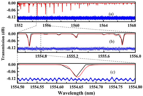
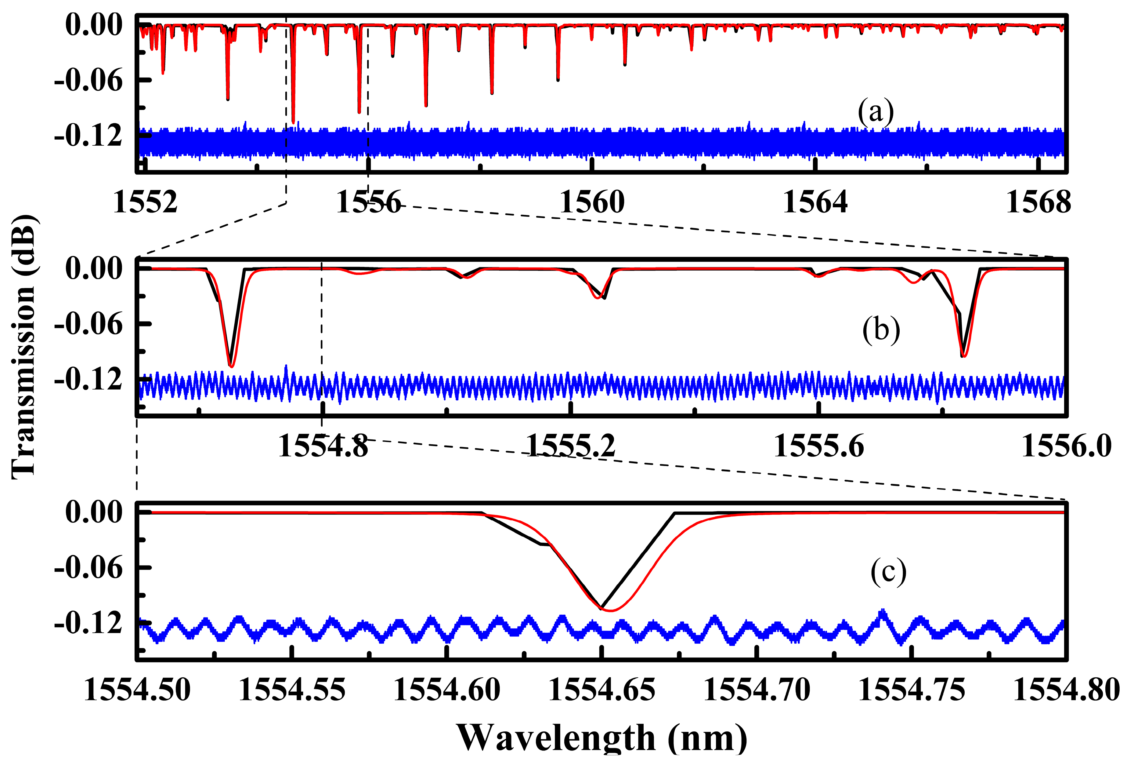
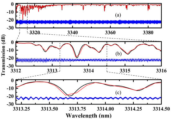
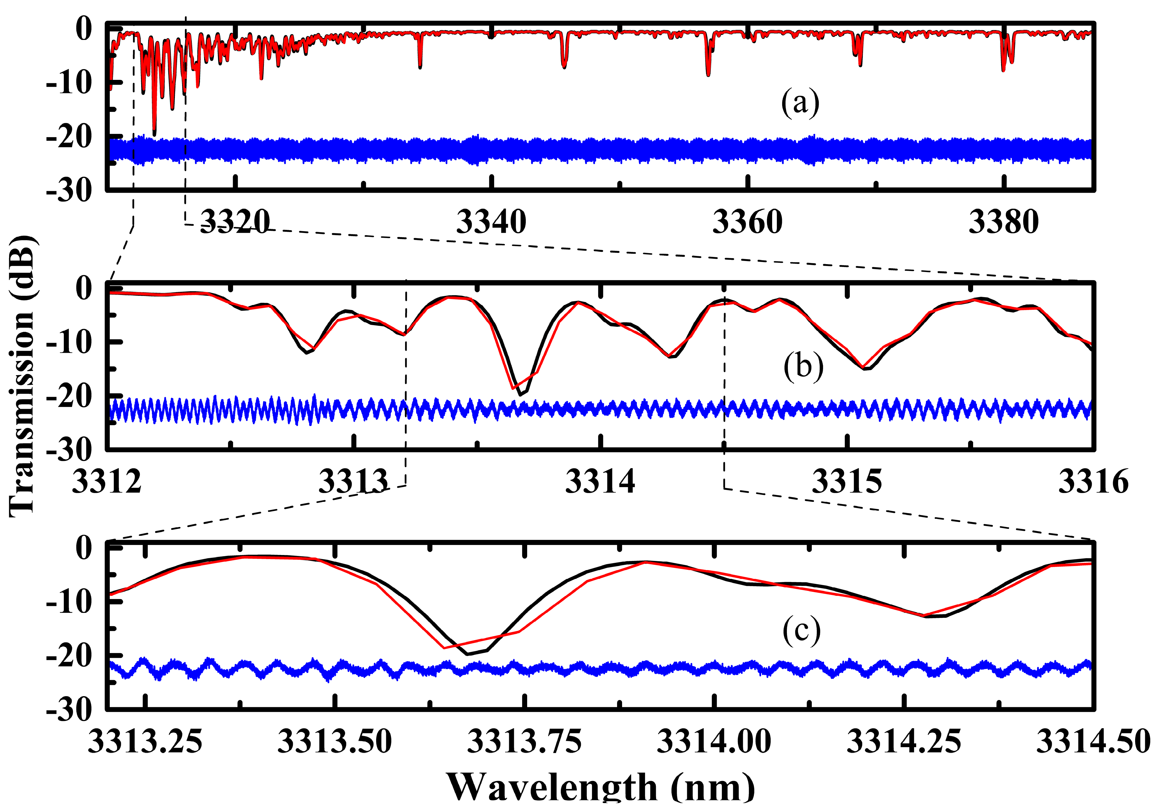
To further verify the continuous MHF tuning operation of the SRO and to calibrate the frequencies of the signal and idler, two gas cells, namely a 25 mm long acetylene (C2H2) gas cell with a pressure of 50 Torr (Bosson laser,Beijing, China) and a 900 mm long methane (CH4) gas cell with a pressure of 600 Torr (Bosson laser, Beijing, China Beijing, China), were employed. Figure 7 and Figure 8 show the transmission spectra of the signal passing through C2H2 and that of the idler passing through CH4, respectively. The red curves are the experimental data, and the black curves are the calculated results derived from high-resolution transmission molecular absorption database (HITRAN) [22]. More concretely, Figure 7a and Figure 8a give the full spectra ranging from 1551.908 nm to 1569.000 nm and from 3386.967 nm to 3309.851 nm, respectively. Figure 7b and Figure 8b give the zoom-in spectra in the ranges from 1554.500 nm to 1556.000 nm and from 3312.000 nm to 3316.000 nm, respectively. Figure 7c and Figure 8c give the zoom-in spectra in the ranges from 1554.500 nm to 1554.800 nm and from 3313.200 nm to 3314.500 nm, respectively. In a continuous MHF tuning process, the absorption features appear at their true spectral positions without distortion or discontinuity. The resolution of the spectral measurements governed by the wavelength sampling step during continuous tuning is 0.05~0.19 nm, which is limited by the acquisition rate rather than by the instrument resolution. The intrinsic resolution of the wavelength meter is about 0.0001 nm. In principle, the spectral resolution of the characterization can be further improved by optimizing the data acquisition device without compromising the MHF tuning performance. Moreover, since the signal is resonated in the cavity, any pump drift propagates directly to the idler frequency. Converting to wavelength via Δλi = λi2Δνi/c, a worst-case pump drift of 4.8 MHz over 30 min (see Supplementary Materials) yields an idler wavelength uncertainty of only Δλi ≈ 0.0002 nm at λi = 3346 nm. For a spectral sampling step of 0.05~0.19 nm, the idler wavelength uncertainty introduced by the pump drift is therefore more than two orders of magnitude smaller than both the sampling step and the absorption linewidth, and has a negligible effect on the calibration of the methane absorption spectrum. From Figure 7 and Figure 8, the measurement spectra clearly resolve the fine absorption features of both acetylene and methane, and show excellent agreement with the HITRAN database, confirming both the MHF nature of the continuous tuning and the accuracy of the frequency calibration.
Figure 7.
The transmission spectrum of the signal passing through the C2H2 cell.
Figure 8.
The transmission spectrum of the idler passing through the CH4 cell.
Moreover, the blue curves at the bottom of Figure 7 and Figure 8 show the signal and idler intensities transmitted through two F-P etalons. In the experiment, a cavity mode hop would produce a phase discontinuity of approximately 4.5 cycles in the etalon transmission fringes (see Supplementary Materials for details), which is well above the detection threshold related to the etalon finesse. Since the transmission curves in Figure 7c and Figure 8c are sinusoidal curves without any phase jumps or discontinuities, the signal and idler from the SRO were confirmed to be continuously MHF-tuned over the full band simultaneously.
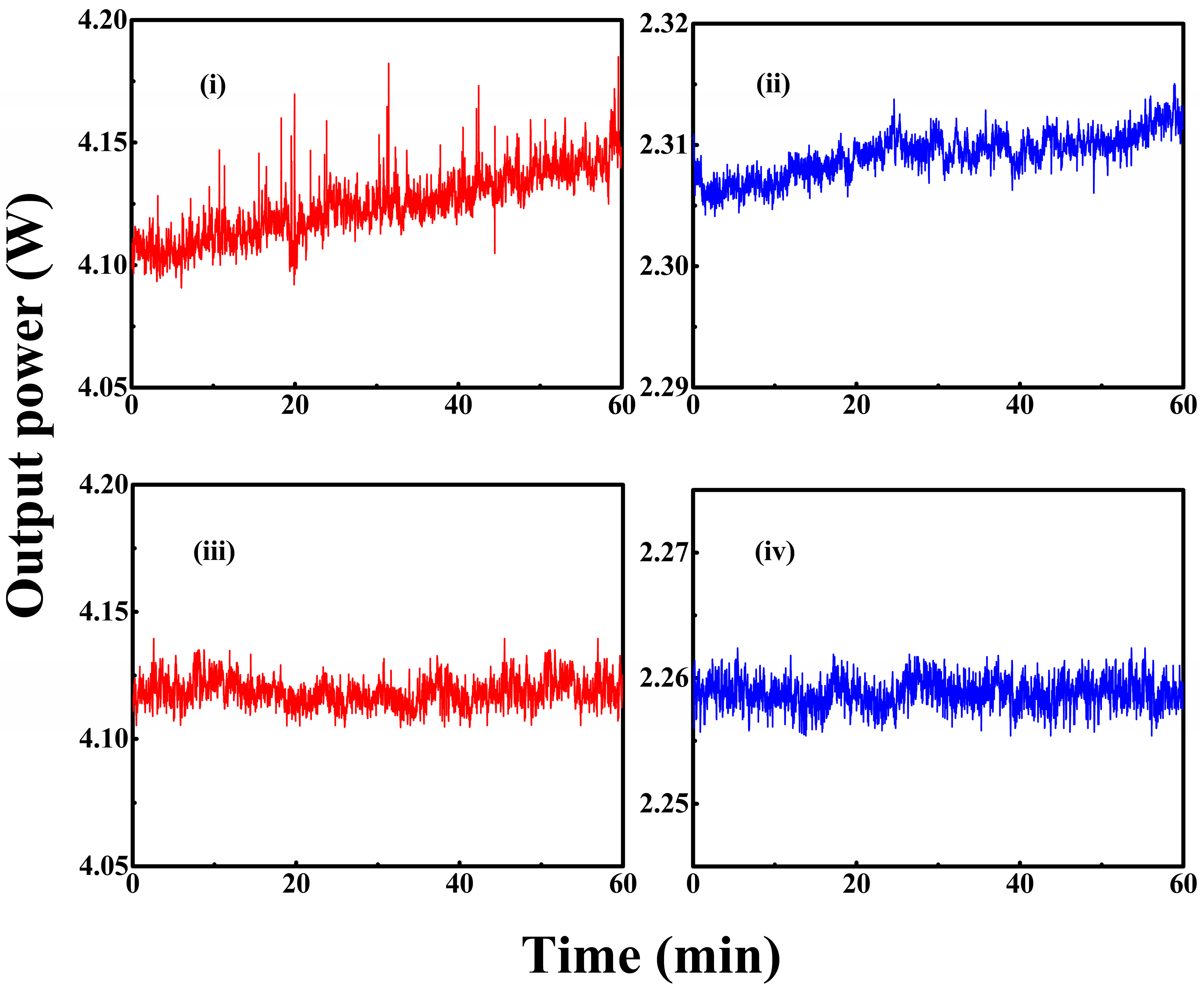
Figure 9 shows the measured powers of the signal and idler for a given one hour without and with the LN etalon angle locked at a pump power of 21 W and a crystal temperature of 46 °C. Without locking, the measured signal power increases from 4.09 W to 4.19 W corresponding to a peak-to-peak power fluctuation of ±1.29%, and the measured idler power increases from 2.30 W to 2.315 W corresponding to a peak-to-peak power fluctuation of ±0.31% (curves (i) and (ii) in Figure 9). When the etalon angle was locked, the measured powers of signal and idler were 4.12 W and 2.26 W with fluctuations reduced to ±0.42% and ±0.18% (curves (iii) and (iv) in Figure 9), respectively. The asymmetric power reduction between signal and idler can be attributed to the following reasons: the non-resonant idler, which is extracted in a single pass, is directly exposed to the conversion efficiency, and additionally suffers the residual 3.3 μm absorption in the crystal, which is the dominant thermal source in cw SROs, whereas the resonated signal is buffered by gain clamping and is essentially free of absorption at 1.56 μm. The slight phase-matching change associated with the thermal re-settling of the crystal upon locking thus lowers the idler channel noticeably while leaving the signal within its own fluctuation band. The improvement in stability arises from the suppression of multimode oscillation. Without the etalon, mode competition induces amplitude noise; with the etalon enforcing single-mode MHF operation, the residual fluctuation is limited to pump intensity noise and slow thermal drift.
Figure 9.
Measured power of the signal (i) and idler (ii) without the angle locking system and that of the signal (iii) and idler (iv) with the angle locking system.
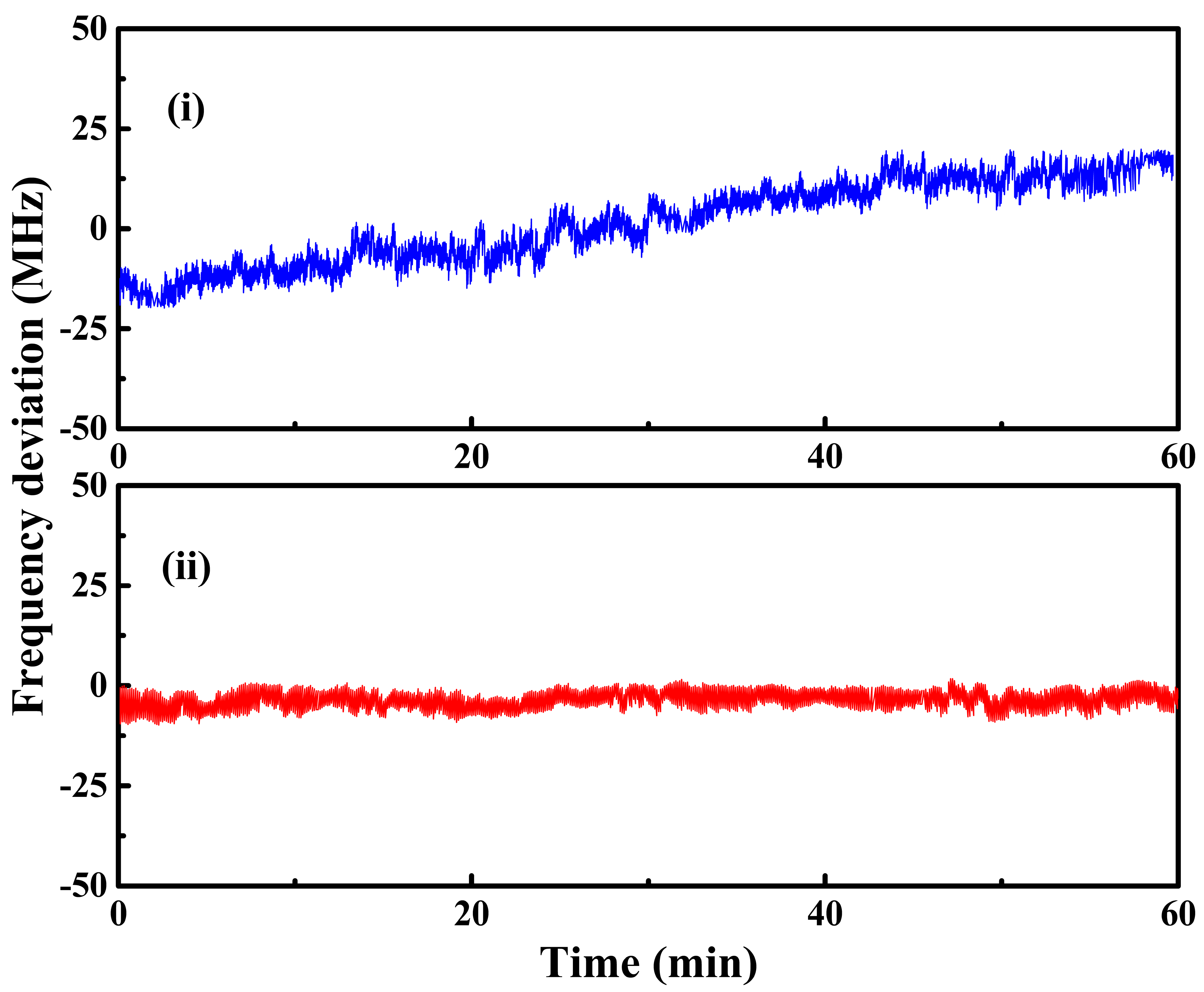
Figure 10 shows the measured frequency drift of the signal at 1560 nm and 4.12 W for a given one hour without and with the LN etalon locking active (curves (i) and (ii) in Figure 10, respectively). Without locking, the signal frequency exhibited a drift of ±30 MHz. With the etalon angle locked, the drift was reduced to ±10 MHz. The corresponding frequency stability of the idler was similarly improved. These results demonstrate that the synchronous etalon-angle tuning and locking system effectively stabilizes both the power and the frequency of the SRO output.
Figure 10.
Measured frequency drift of the signal without (i) and with (ii) the angle locking system.
The beam quality was characterized using a scanning beam profiler (Spiricon M2-200-BB) at a pump power of 21 W and a crystal temperature of 46 °C. For the output signal beam, the measured M2 factors are 1.13 (horizontal) and 1.31 (vertical). During the wavelength tuning and pump power variation, the variation in M2 factors remained below ±0.1, indicating weak beam degradation at this pumping level.
5. Conclusions
We demonstrated a cw SRO based on a MgO:PPLN crystal that achieves broadband mode-hop-free tuning of both signal and idler through crystal temperature tuning, operating at a pump power eight times the oscillation threshold. We first theoretically analyzed the intrinsic modulation instability that triggers mode hops at elevated pump powers, and then derived the condition for broadband MHF tuning that was the temperature-dependent optimal angle of the intracavity etalon. Guided by this theoretical analysis, a synchronous etalon-angle tuning and locking system was developed to suppress the modulation-instability-induced mode hops. To eliminate thermally triggered mode hops, a program-controlled digital temperature controller with nonlinearly optimized feedback was implemented, achieving a temperature fluctuation below 0.1 °C and a tuning speed of 0.12 °C/s. Using the above-developed techniques, the signal wavelength was continuously MHF-tuned from 1551.9087 nm to 1568.6549 nm when the pump power was 21 W and the crystal temperature was ramped from 20 °C to 70 °C. The corresponding idler tuning range was from 3384.3030 nm to 3307.3073 nm, indicating a continuous MHF tuning bandwidth of 2.064 THz at a tuning speed of 4.7 GHz/s. This result presents, to our knowledge, the widest continuous MHF tuning bandwidth reported for a temperature-tuned cw SRO. The MHF characteristic of the continuous tuning operation was experimentally verified through high-resolution absorption spectroscopy of C2H2 and CH4. The absorption features appeared at their predicted spectral positions without discontinuities, and the measured line shapes were in excellent agreement with HITRAN simulations. Further confirmation was provided by the continuous sinusoidal transmission pattern recorded with external F-P etalons. When the SRO was operated at a fixed temperature of 46 °C and a pump power of 21 W, the measured powers of the signal at 1560 nm and idler at 3346 nm were 4.12 W and 2.26 W with power fluctuations of ±0.42% and ±0.18%, respectively. The frequency drift of both signal and idler was below ±10 MHz over one hour, confirming the effectiveness of the etalon-angle locking system for long-term operation. This kind of broadband continuous MHF tunable SRO with watt-level output and high tuning speed is well-suited for high-resolution spectroscopic applications including multi-species trace-gas detection and atmospheric monitoring. Further bandwidth extension can be pursued by cascading multiple poling periods or by implementing an upgraded temperature control system providing higher heating efficiency to extend the crystal temperature range beyond 20–70 °C.
Supplementary Materials
The following supporting information can be downloaded at https://www.mdpi.com/article/10.3390/photonics13080790/s1: supplemental document: SM-Broadband continuous mode-hop-free tunable singly resonant optical parametric oscillator.
Author Contributions
Conceptualization, K.Z. and Y.L.; methodology, K.Z. and M.Q.; software, Y.L. and M.Q.; validation, M.Q. and R.L.; investigation, M.Q., R.L., Y.L. and J.F.; resources, K.Z. and J.F.; data curation, M.Q. and Y.L.; writing—original draft preparation, Y.L.; writing—review and editing, Y.L., K.Z. and M.Q.; visualization, M.Q. and R.L.; supervision, K.Z.; project administration, K.Z.; funding acquisition, K.Z. All authors have read and agreed to the published version of the manuscript.
Funding
This research was funded by the National Natural Science Foundation of China (NSFC) (Grant No. U24A20321).
Data Availability Statement
The data underlying the results presented in this paper are not publicly available at this time but may be obtained from the authors upon reasonable request.
Conflicts of Interest
The authors declare no conflicts of interest.
Abbreviations
The following abbreviations are used in this manuscript:
| MHF | Mode-hop-free |
| SRO | Singly resonant optical parametric oscillator |
| HCN | Hydrogen cyanide |
| cw | Continuous-wave |
| SLM | Single-longitudinal-mode |
| OPO | Optical parametric oscillator |
| ECDL | Extended-cavity diode laser |
| PZT | Piezoelectric transducer |
| LN | Lithium niobate |
| TMHF | Temperature range |
| HT | High-transmission |
| HR | High-reflection |
| LD | Laser diode |
| DC | Direct current |
| LIA | Lock-in amplifier |
| PIA | Proportional–integral amplifier |
| ADD | Adder |
| MZI | Mach–Zehnder interferometer |
| TEC | Thermoelectric cooler |
| HITRAN | High-resolution transmission molecular absorption database |
References
- Sperling, J.; Schubert, M.H.; Wenderoth, M.; Hens, K. Breakthrough instruments and products: Laser light tunable across the visible up to mid-infrared: Novel turnkey cw OPO with efficiency-optimized design. Rev. Sci. Instrum. 2021, 92, 129502. [Google Scholar] [CrossRef] [Scilit] [PubMed]
- Kavita, D.; Ebrahim-Zadeh, M. Widely tunable room-temperature green-pumped continuous-wave optical parametric oscil-lator from the red to mid-infrared. J. Opt. Soc. Am. B 2023, 40, 1960–1967. [Google Scholar] [CrossRef] [Scilit]
- Kolker, D.B.; Sherstov, I.V.; Boyko, A.A.; Nyushkov, B.N.; Erushin, E.Y.; Kostyukova, N.Y.; Akhmathanov, A.I.; Kiryakova, A.Y.; Pavluck, A.V. Tunable mid-infrared laser sources for trace-gas analysis. J. Phys. Conf. Ser. 2021, 2067, 012013. [Google Scholar] [CrossRef] [Scilit]
- Corato-Zanarella, M.; Gil-Molina, A.; Ji, X.C.; Shin, M.C.; Mohanty, A.; Lipson, M. Widely tunable and narrow-linewidth chip-scale lasers from near-ultraviolet to near-infrared wavelengths. Nat. Photonics 2023, 17, 157–164. [Google Scholar] [CrossRef] [Scilit]
- Hu, B.Y.; Xu, C.Y.; Zhang, K.; Yao, H.Q.; Lv, X.J.; Ning, J.; Zhao, G.; Zhu, S.N. High-performance, narrow-linewidth, widely-tunable, and highly-stable optical parametric oscillator and its application in cantilever-enhanced photoacoustic spectroscopy for gas detection. Laser Phys. Lett. 2026, 23, 045001. [Google Scholar] [CrossRef] [Scilit]
- Wang, P.; Cheng, X.; Li, X.; Xu, X.J. Tunable dual-wavelength, continuous-wave, mid-infrared generation using intracavity difference frequency mixing in PPLN-based optical parametric oscillator. IEEE J. Sel. Top. Quant. 2018, 24, 0902807. [Google Scholar] [CrossRef]
- Wu, H.S.; Wang, P.; Song, J.X.; Ye, J.; Xu, J.M.; Li, X.; Zhou, P. High power tunable mid-infrared optical parametric oscillator enabled by random fiber Laser. Opt. Express 2018, 26, 6446–6455. [Google Scholar] [CrossRef] [Scilit] [PubMed]
- Wang, K.; Gao, M.Y.; Yu, S.H.; Ning, J.; Xie, Z.D.; Lv, X.J.; Zhao, G.; Zhu, S.N. A compact and high efficiency intracavity OPO based on periodically poled lithium niobate. Sci. Rep. 2021, 11, 5079. [Google Scholar] [CrossRef] [Scilit] [PubMed]
- Le, Y.; Ding, Z.W.; Liu, P.; Chen, G.H.; Zhang, Z.W. Widely tunable, continuous-wave, intra-cavity optical parametric oscillator based on an Yb-doped fiber laser. Opt. Lett. 2018, 43, 5391–5394. [Google Scholar] [CrossRef] [Scilit] [PubMed]
- Herpen, M.V.; Hekkert, S.L.; Bisson, S.E.; Harren, F.J.M. Wide single-mode tuning of 3.0-3.8 μm, 700 mW, continuous-wave Nd:YAG-pumped optical parametric oscillator based on periodically poled lithium niobate. Opt. Lett. 2002, 2, 640–642. [Google Scholar]
- Hong, X.P.X.; Shen, L.; Gong, M.L.; Wang, F. Broadly tunable mode-hop-free mid-infrared light source with MgO:PPLN continuous-wave optical parametric oscillator. Opt. Lett. 2012, 37, 4982–4984. [Google Scholar] [CrossRef] [Scilit] [PubMed]
- Phillips, C.R.; Fejer, M.M. Stability of the singly resonant optical parametric oscillator. J. Opt. Soc. Am. B 2010, 27, 2687–2699. [Google Scholar] [CrossRef] [Scilit]
- Courtois, J.; Bouchendira, R.; Cadoret, M.; Ricciardi, I.; Mosca, S.; Rosa, M.; Natale, P.; Zondy, J.J. High-speed multi-THz-range mode-hop-free tunable mid-IR laser spectrometer. Opt. Lett. 2013, 38, 1972–1974. [Google Scholar] [CrossRef] [Scilit] [PubMed]
- Strößner, U.; Meyn, J.P.; Wallenstein, R.; Schiller, S.; Peters, A. Single-frequency continuous-wave optical parametric oscillator system with an ultrawide tuning range of 550 to 2830 nm. J. Opt. Soc. Am. B 2002, 19, 1419–1424. [Google Scholar] [CrossRef] [Scilit]
- Vainio, M.; Peltola, J.; Persijn, S.; Harren, F.J.M.; Halonen, L. Singly resonant cw OPO with simple wavelength tuning. Opt. Express 2008, 16, 11141–11146. [Google Scholar] [CrossRef] [Scilit] [PubMed]
- Hu, L.; He, Y.; Lv, X.; Ning, J.; Zhao, G.; Zhu, S. A passively wavelength-stabilized mid-infrared optical parametric oscillator. Photonics 2023, 10, 5. [Google Scholar] [CrossRef] [Scilit]
- Foote, D.B.; Cich, M.J.; Hurlbut, W.C.; Eismann, U.; Heiniger, A.T.; Haimberger, C. High-resolution, broadly-tunable mid-IR spectroscopy using a continuous wave optical parametric oscillator. Opt. Express 2021, 29, 5295–5303. [Google Scholar] [CrossRef] [Scilit] [PubMed]
- Paul, O.; Quosig, A.; Bauer, T.; Nittmann, M.; Bartschke, J.; Anstett, G.; L’huillier, J.A. Temperature-dependent Sellmeier equation in the MIR for the extraordinary refractive index of 5% MgO doped congruent LiNbO3. Appl. Phys. B 2007, 86, 111–115. [Google Scholar] [CrossRef] [Scilit]
- Vainio, M.; Peltola, J.; Persijn, S.; Harren, F.J.M.; Halonen, L. Thermal effects in singly resonant continuous-wave optical parametric oscillators. Appl. Phys. B 2009, 94, 411–427. [Google Scholar] [CrossRef] [Scilit]
- Hobden, M.V.; Warner, J. The temperature dependence of the refractive indices of pure lithium niobate. Phys. Lett. 1966, 22, 243–244. [Google Scholar] [CrossRef] [Scilit]
- Kim, Y.S.; Smith, R.T. Thermal expansion of lithium tantalate and lithium niobate single crystals. J. Appl. Phys. 1969, 40, 4637–4641. [Google Scholar]
- Gordon, I.E.; Rothman, L.S.; Hargreaves, R.J.; Gomez, F.M.; Bertin, T.; Hill, C.; Kochanov, R.V.; Tan, Y.; Wcisło, P.; Makhnev, V.Y.; et al. The HITRAN2024 molecular spectroscopic database. J. Quant. Spectrosc. Radiat. Transf. 2026, 353, 109807. [Google Scholar] [CrossRef] [Scilit]
Disclaimer/Publisher’s Note: The statements, opinions and data contained in all publications are solely those of the individual author(s) and contributor(s) and not of MDPI and/or the editor(s). MDPI and/or the editor(s) disclaim responsibility for any injury to people or property resulting from any ideas, methods, instructions or products referred to in the content. |
© 2026 by the authors. Licensee MDPI, Basel, Switzerland. This article is an open access article distributed under the terms and conditions of the Creative Commons Attribution (CC BY) license.