


Abstract
Discrete energy-level dynamics provide a fundamental framework for understanding driven two-state systems. Here, we propose and experimentally demonstrate a classical microwave-photonic analog based on two active fiber loops. Reciprocal electro-optic sidebands coherently couple two independently sustained lasing modes. When the input RF power is increased from 11.7 to 18.7 dBm, the measured oscillation frequency increases from 0.55 to 1.00 MHz, consistent with the modulation-induced coupling predicted by the coupled-mode model. The experiment therefore demonstrates RF-power-controlled Rabi-like oscillation in an active dual-loop system. Because the optical fields and detected intensities are classical, the platform reproduces reduced two-state dynamics rather than quantum-state evolution. This proof-of-concept provides a basis for quantum-inspired microwave-photonic signal processing and future short-cavity implementations.
1. Introduction
Rabi pioneered the theory of driven two-level systems by analyzing state transitions among discrete magnetic sublevels under rotating radio-frequency fields [1]. After the emergence of coherent laser sources, this theoretical framework was generalized from radio-frequency (RF) and microwave regimes to optical two-level systems, which are formally characterized by optical Bloch equations, Rabi flopping, and optical nutation. Allen and Eberly provided a comprehensive derivation for optical two-level dynamics [2]. Such coherent principles further facilitate the development of parity-time symmetry photonics [3,4], topological photonics [5,6], and quantum photonics [7,8]. In this work, we adopt the simplified coupled-state formalism for classical dynamical analogy, rather than quantizing the involved optical fields.
While quantum systems provide foundational insights into discrete energy dynamics, recent advances in microwave photonics have enabled the classical emulation of these phenomena. As an interdisciplinary field exploring interactions between optical and RF signals, microwave photonics has attracted increasing attention due to its inherent ultrafast response time, wide processing bandwidth, and programmable architecture [9,10,11]. Electro-optic modulation, which is fundamental to microwave photonics, has driven the development of technologies such as opto-electronic oscillators (OEOs) [12,13], microwave photonic radar [14], and electro-optical frequency combs [15,16]. In recent years, the analogy between photonic systems and non-Hermitian quantum systems has led to innovations such as PT-symmetric OEOs [17,18,19] and photonic molecules [20,21,22]. However, while most studies have focused on spectral and topological properties, such as synthetic dimensions [23,24,25], analogies to energy level dynamics in atomic systems remain relatively unexplored. It is affirmed by Spreeuw et al. that electro-optic modulation can emulate particle energy-level transitions [26], enabling coherent coupling of discrete photon energy levels through purely classical methods. Therefore, it is possible to achieve emulation of energy level dynamics by electro-optic interactions [27], offering a powerful paradigm for classical realization of quantum phenomena.
Previous classical realizations of two-level and related coherent dynamics include passive photonic molecules, gain-assisted optical rings, nanomechanical resonators, and synthetic-frequency platforms [24,26,27,28]. A quantitative comparison with representative classical platforms for two-level and related coherent dynamics is provided in Table 1. Different from passive resonator-based systems that require external optical excitation, the proposed architecture employs two independently sustained lasing modes in separate active fiber loops. Reciprocal first-order sidebands generated by electro-optic phase modulation coherently couple the two modes. Thus, the input RF signal power controls the modulation index β, the coupling strength κ, and the measured oscillation frequency. Table 1 also includes a synthetic-dimension resonator to clarify the distinction between an extended multimode frequency lattice and the selected two-state subspace used here. The active dual-loop structure provides a direct microwave photonic analogy to a driven two-level system. For an FSR of 6 MHz, the measured oscillation frequency is tuned from 0.55 to 1.00 MHz as the RF power is increased from 11.7 to 18.7 dBm. However, the long cavities and multimode operation still limit the compactness and stability of the present system. These limitations motivate future short-cavity or integrated implementations.
Table 1.
Comparison of representative classical platforms for two-level and related coherent dynamics.
2. Principle and Analysis
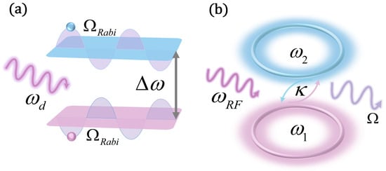
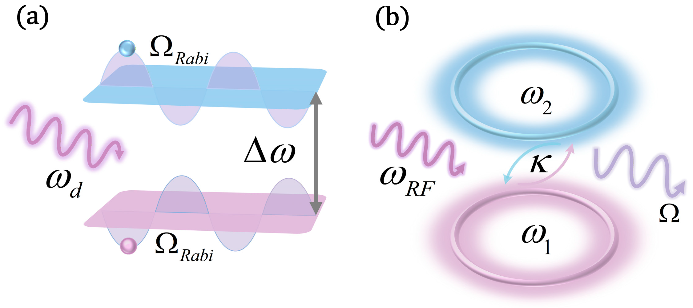
The design concept of the proposed microwave photonic two-level system is depicted in Figure 1a,b. When the carrier frequency in one loop matches the sideband frequency generated in the other loop, a coherent coupling between the two loops is achieved due to resonant sideband coupling induced by the modulated RF signal, enabling effective energy exchange. This periodic energy exchange between the two loops is analogous to Rabi oscillation in atomic two-level systems, where population oscillates between the two energy levels due to resonant interaction with an external driving field, as shown in Figure 1. The dependence of the oscillation frequency on the input RF signal power mirrors the dynamics of Rabi oscillation in an atomic system, reflecting a classical analog to a quantum two-level system.
Figure 1.
Conceptual illustration of the classical microwave-photonic two-state analogy. (a) A driven atomic two-level system exhibits periodic population exchange under resonant coupling. (b) In the proposed system, two selected lasing modes at ω1 and ω2 form the effective states, while reciprocal electro-optic sidebands provide the external coupling. The measured photodetected signals are classical optical intensities rather than quantum-state populations. Blue and purple distinguish the two states, while the arrows and wavy lines schematically indicate the labeled driving and coupling processes. The colors do not encode numerical values.
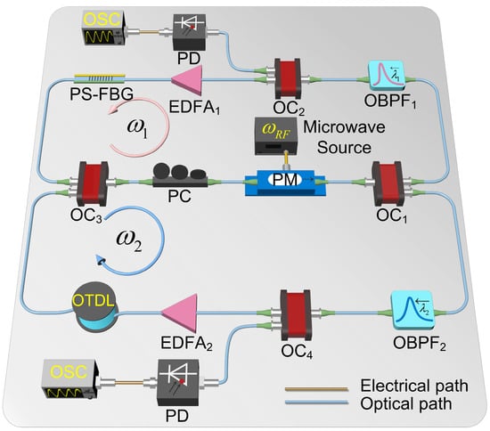
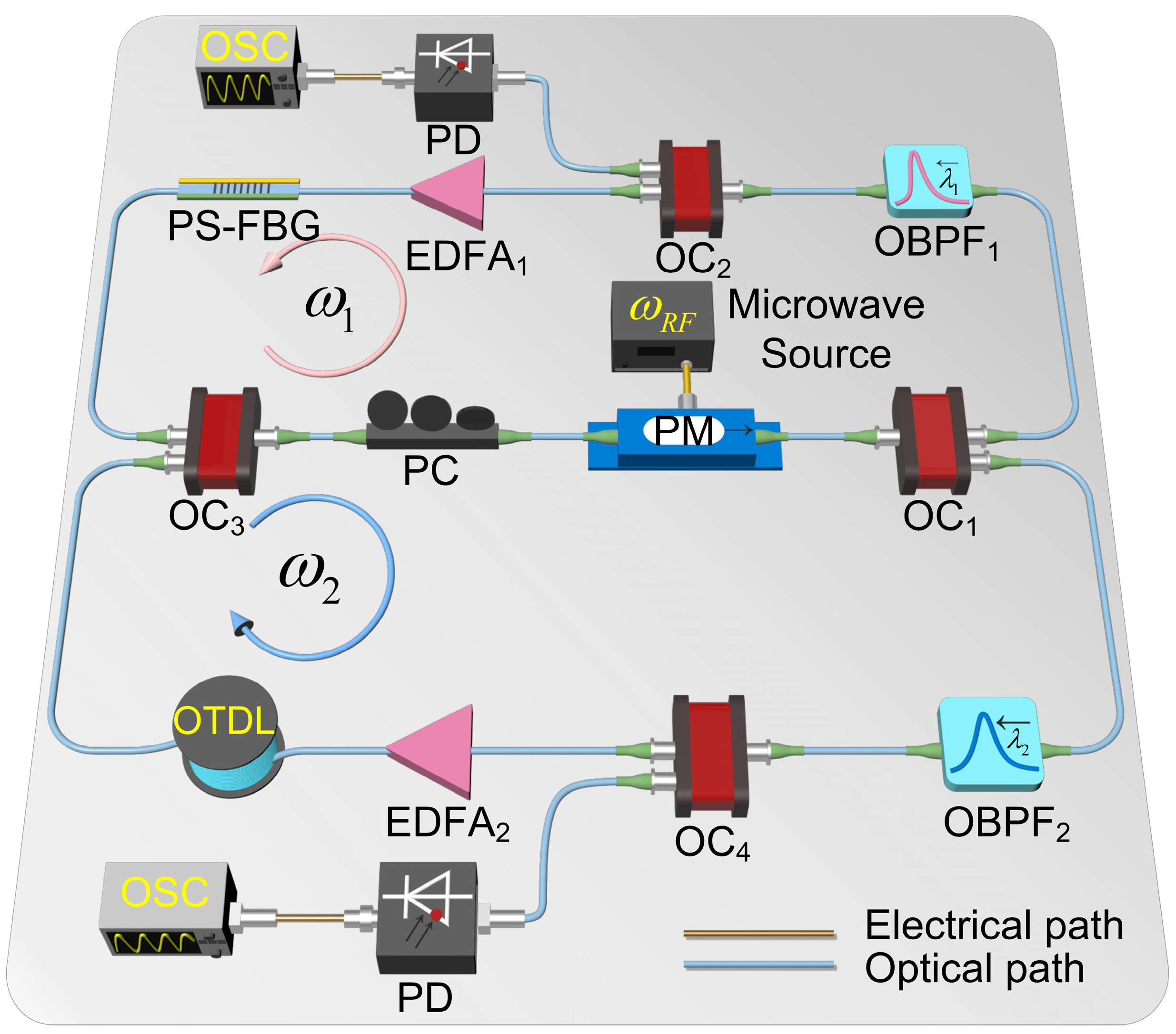
The schematic of the proposed microwave photonic two-level system is shown in Figure 2. The system consists of two coupled fiber loops, each functioning as a fiber ring laser. Each loop contains an erbium-doped fiber amplifier (EDFA) serving as the gain medium and an optical band-pass filter (OBPF) that determines the lasing frequency (ω1 for the upper loop and ω2 for the lower loop). Crucially, both loops are designed to have an identical round-trip time, which is achieved by tuning the optical tunable delay line (OTDL) in the lower loop. The two co-propagating optical beams generated within each loop are phase-modulated at a phase modulator (PM) driven by an external RF signal at frequency ωRF, which is generated by a microwave generator. This modulation generates sidebands around the carrier frequencies at ω1 ± nωRF and ω2 ± nωRF, where n is an integer. The modulated light is then split at an optical coupler, OC1, and sent to the two loops, where the light is filtered by the OBPF within each loop. Specifically, the upper-loop OBPF1 is configured to transmit both its own lasing frequency ω1 and the key sideband component ω2 − ωRF generated in the lower loop. The lower-loop OBPF2 selectively transmits its lasing frequency ω2 along with the critical sideband component ω1 + ωRF generated in the upper-loop. A phase-shifted fiber Bragg grating (PS-FBG) is employed to narrow the optical passband and suppress non-primary longitudinal modes. This reduces mode competition and the probability of mode hopping. However, the cavity-mode spacing is much smaller than the filter bandwidth. The PS-FBG therefore improves longitudinal-mode selectivity, although single-longitudinal-mode operation is not established in the present experiment. The light waves from the two loops recombine at a second OC (OC2) and are sent to the PM. This dual-path filtering strategy actively establishes coherent coupling between the two loops. A polarization controller (PC) placed before the PM is used to align the polarization state of the incident light to minimize the polarization-dependent loss at the PM. To monitor the operations of the system, two other OCs (OC3 and OC4) are used to tap off a small portion of the light propagating in the upper and lower loops, respectively. To verify the existence of Rabi-like oscillation, a photodetector (PD) is used in each loop to detect the optical signal, where the oscillating coupling between the two loops could be observed manifesting as an RF signal at the output of the PD. The electrical signals after the PDs are then monitored using a real-time oscilloscope (OSC). The frequency of this output RF signal oscillation is directly controlled by the power of the input RF signal applied to the PM. Thus, by adjusting the input RF signal power, the effective coupling strength is tuned, enabling observation of the corresponding variations in the oscillation frequency.
Figure 2.
Schematic and experimental setup of the proposed microwave photonic two-level system that enables the observation of analogous Rabi oscillations. OC: optical coupler; PM: phase modulator; OBPF: optical band-pass filter; EDFA: erbium-doped fiber amplifier; PC: polarization controller; PD: photodetector; OSC: oscilloscope; PS-FBG: phase-shifted fiber Bragg grating; OTDL: optical tunable delay line.
The Hamiltonian describing an atomic two-level system under an external driving field is given by
where a (a†) and b (b†) are the annihilation (creation) operators of the two energy states of the respective energy levels, V is the coupling strength between the two energy states, and ωd is the driving frequency. For simplicity, we set ℏ = 1 hereafter. By applying a unitary transformation U = exp{j[(ω1a†a + ω2b†b)t]/2} and the rotating wave approximation (RWA), we obtain the following equation of motion using input–output theory,
where Δ = Δω − ωd is the detuning in the rotating frame. The form of the expression shown in Equation (2) is the standard representation of a two-level system described in the rotating frame. This implies that any system whose equation of motion can be reduced to this form is capable of exhibiting Rabi oscillation.
In our proposed system, assuming that a lasing signal with expression Einexp(jωct), where ωc is the lasing frequency, is modulated by an RF signal given by VRFcos(ωRFt + φRF) at the PM, the electric field after the PM can be expressed as
where Ein and Eout are the electric fields at the input and output of the PM, respectively, β = πVRF/Vπ is the modulation index, and Vπ is the half-wave voltage of the PM. VRF = (2PRFR)1/2 is the amplitude of the RF signal when PRF is the power of the input RF signal, with the angular frequency ωRF and phase φRF. R = 50 Ω is the impedance of the PM. Applying the Jacobi–Anger expansion to Equation (3), we have
where Jn(·) is the nth Bessel function of the first kind. As can be seen, the electric field at the output of the PM consists of different orders of sidebands.
According to Equation (4), phase modulation generates optical sidebands of multiple orders at the output of the PM. In the present configuration, the OBPFs and the PS-FBG are arranged to transmit only the carrier components and the reciprocal +1st- and −1st-order sidebands required for coupling between the two selected lasing modes. Higher-order sidebands lie outside the corresponding loop passbands and are largely rejected from the resonant intracavity coupling paths. Because the filter extinction is finite, weak residual components may still introduce parasitic beating. Accordingly, the coupled-mode model retains only the selected first-order exchange channels.
By configuring the OBPFs within the two loops to selectively transmit the +1st sideband from the upper loop to the lower loop and the −1st sideband from the lower loop to the upper loop, coherent optical-RF signal coupling is thus established. This bidirectional sideband exchange enables synthetic two-level dynamics in the photonic system. The coupling strength κ is governed by the modulation strength J1(β) and the round-trip time τ and is given by
By substituting Equation (8) into Equation (7), employing the RWA, and eliminating high-frequency oscillatory terms [30], Equation (7) is simplified to be
where δ = ωRF − Δω is the microwave frequency detuning, and Δω = ω2 − ω1 and Δγ = γ2 − γ1 are the lasing frequency and gain difference between the upper and lower loops, respectively. Clearly, Equation (9) has the same form as Equation (2), which demonstrates that the microwave-photonics system here is analogous to an atomic two-level system where Rabi oscillation can be established if an external field is applied.
By solving Equation (9), we obtain
where A0 and B0 are the initial states of the upper loop and lower loops, respectively. The characteristic oscillation angular frequency Ω is governed by
The oscillation angular frequency Ω manifests as a frequency-splitting phenomenon during microwave phase modulation. This mechanism is analogous to the Autler-Townes splitting (also known as Rabi-splitting) in an atomic two-level system [31]. The value of Ω depends on the coupling strength κ, which incorporates the contributions from the microwave detuning δ and the gain difference Δγ. Under the approximately balanced-gain condition (Δγ ≈ 0), Equation (11) reduces to Ω = (4κ2 + δ2)1/2, where δ = ωRF − Δω is the RF-frequency detuning. This expression predicts a generalized Rabi-like oscillation frequency that depends on both the modulation-induced coupling strength and the frequency detuning. At the same time, the efficiency of energy exchange between the two photonic states is expected to decrease away from resonance. Therefore, detuning-dependent measurements of both the oscillation frequency and oscillation contrast would provide a more comprehensive experimental test of the proposed mechanism. However, such measurements are beyond the scope of the present proof-of-concept experiment and will be investigated in future work.
Equation (11) also describes the effects of frequency detuning and differential gain or loss. For Δγ = 0, Ω = (4κ2 + δ2)1/2, while the ideal maximum transfer from one effective state to the other is 4κ2/(4κ2 + δ2). Thus, detuning reduces the exchange contrast even though the generalized oscillation frequency increases. When Δγ is nonzero, the eigenvalue splitting becomes complex. The gain or loss difference can cause unequal growth or decay, reduce the measured contrast, and distort the sinusoidal waveform. A common gain or loss applied equally to both modes mainly changes the common envelope and threshold, whereas the differential term changes the coupled-mode dynamics. Therefore, Equations (12)–(15) describe the resonant and balanced-gain condition used to analyze the RF-power dependence.
Equation (11) indicates that a sinusoidal signal with an angular frequency Ω/2 can be obtained by injecting an RF signal into the system. For example, if we set A0 = 0 and B0 = 1 to be the initial states of the two loops, we obtain
Under the resonant condition (δ = 0) with the balanced gain (Δγ = 0) between the two loops, Equations (12) and (13) reduce to Ω = 2κ. This implies the oscillation angular frequency Ω is proportional to the coupling strength κ, which is determined by the modulation strength J1(β) and the round-trip time τ. The RF signals at the outputs of the PDs are then given by
Equations (14) and (15) describe the interaction between the two loops under the resonant and balanced gain conditions (δ = 0 and Δγ = 0). The angular frequency of the oscillation is directly controlled by the coupling strength κ = J1(β)/τ, indicating that the oscillation angular frequency Ω is governed by the modulation index β when the round-trip time τ is fixed. Since β is proportional to the amplitude of the input RF signal VRF, which is given by VRF = (2PRFR)1/2, the oscillation angular frequency Ω can be controlled by changing the input RF signal power PRF. By varying PRF, κ is changed, resulting in the corresponding shift in the value of Ω. This behavior manifests as oscillation at the output of the two loops, analogous to Rabi oscillation in an atomic two-level system. This phenomenon constitutes a microwave photonic analog of Rabi oscillation. Notably, the oscillations at the output of the two loops have the same oscillation frequency, differing only in phase. Consequently, observing a sinusoidal signal with the angular frequency ωRF,out = 2J1(β)/τ, corresponding to an oscillation frequency fosc = ωRF,out/(2π) in one loop, implies the same frequency exists in the other, differing solely by a relative π-phase shift.
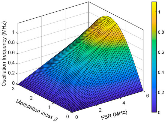
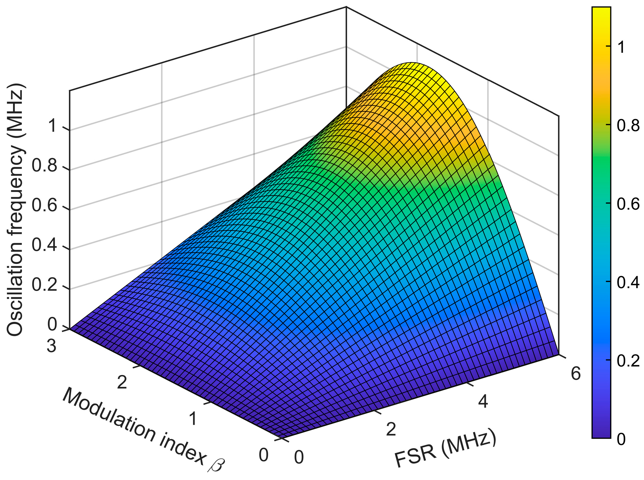
A zero-detuned simulation of the proposed microwave photonic two-level system based on the schematic in Figure 2 is presented in Figure 3. The figure illustrates the dependence of the oscillation frequency on the FSR, which is determined by the round-trip time τ of the system, and the modulation index β. As β increases, the oscillation frequency initially rises and reaches a maximum, after which further increases in β cause the oscillation frequency to decline. This dynamic behavior is in excellent agreement with the first-order Bessel function J1(β). In the meantime, the oscillation frequency increases with larger FSR values, consistent with the inverse dependence on the round-trip time τ. The simulation results in Figure 3 are consistent with Equations (14) and (15), which establishes the relationship between the oscillation frequency, the modulation index β, and the round-trip time τ. These results confirm the feasibility of controlling the output RF frequency by tuning the injected RF power, demonstrating the practicality of realizing a microwave photonic two-level system.
Figure 3.
Zero-detuned simulation of proposed microwave photonic two-level system.
3. Results
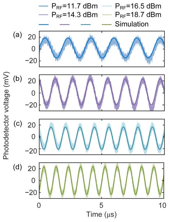
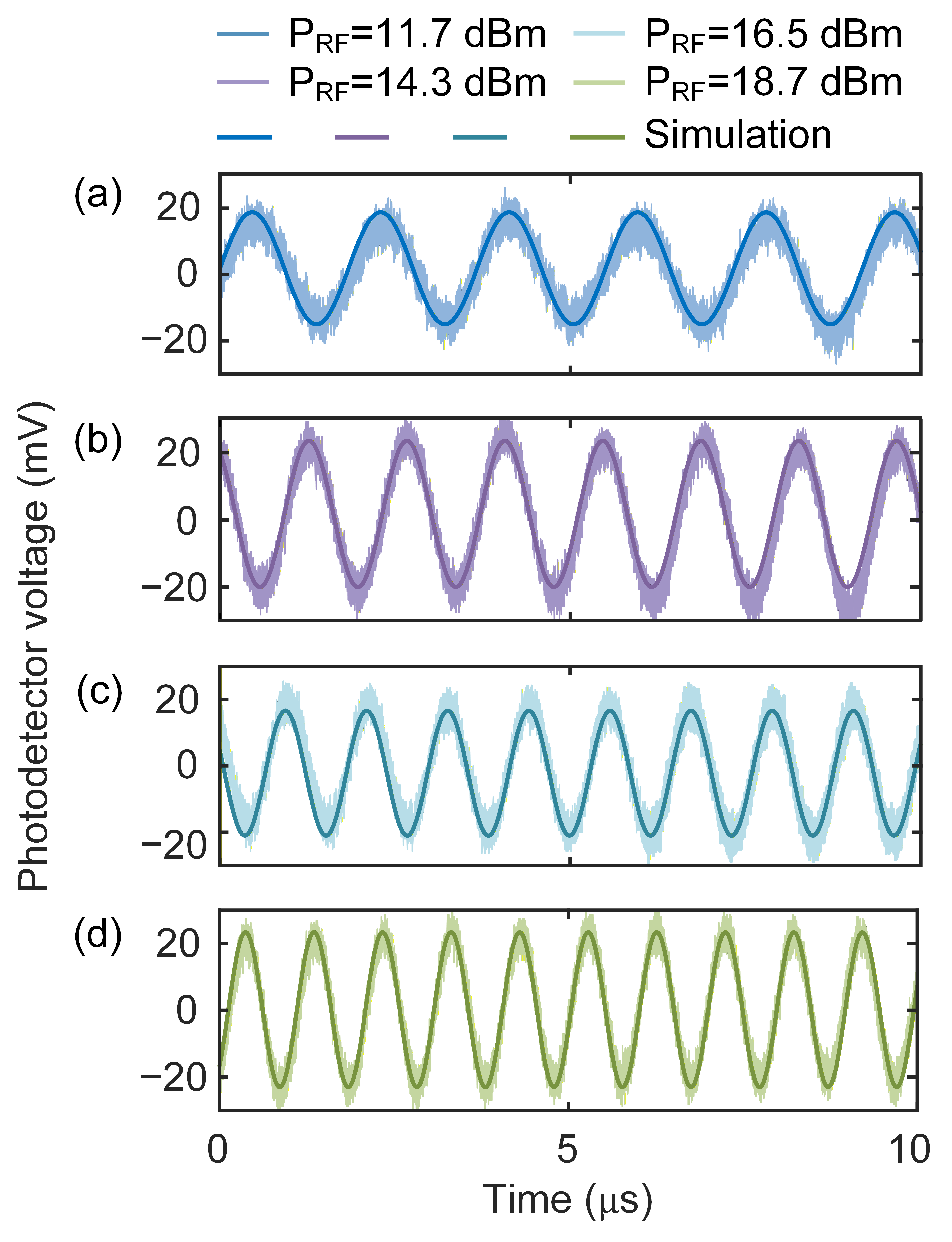
An experiment is performed using the setup shown in Figure 2 to assess the operation of the proposed microwave photonic two-level system. The system consists of two fiber ring lasers with the upper loop lasing at ω1 and the lower loop lasing at ω2. In each loop, an EDFA is incorporated to provide the optical gain. The optical beams from the two lasers are coupled via OC2, and the combined beam is sent to the PM ( MPZ-LN-40, Photline Technologies, Besançon, France) with a 40 GHz electro-optic bandwidth and a half-wave voltage Vπ = 6.4 V, to which an external RF signal is applied. The RF signal with a tunable frequency ωRF is generated by a microwave generator (HMC-T2240, Hittite Microwave Corporation, Chelmsford, MA, USA). At the output of the PM, a phase-modulated optical signal consisting of different orders of optical sidebands is generated. Note that the RF signal applied to the PM serves as an external driving field, analogous to the external field applied to a two-level atomic system. The modulated light is subsequently split by OC1 and filtered by the OBPFs within the two loops. Specifically, the upper loop can only pass light waves with frequencies ω1 and ω2 − ωRF, while the lower loop can only pass light waves with frequencies ω2 and ω1 + ωRF, as was discussed in the previous section. Note that the PS-FBG served as a passband filter with a bandwidth of 200 MHz, is employed in the upper loop, while an OTDL in the lower loop is used to match the optical path lengths of the two loops. A small portion (10%) of the optical power after each OBPF is extracted. The light waves at the output of OC3 and OC4 are detected by the two high-speed PDs with a 20 GHz bandwidth. The electrical signals after the PDs are then monitored using a real-time OSC (LabMaster MCM-Zi with a LabMaster 10-36Zi-A acquisition module, Teledyne LeCroy, Chestnut Ridge, NY, USA) with a maximum bandwidth of 36 GHz. By adjusting the OTDL in the lower loop, the FSR of the two loops is matched to be 6 MHz, corresponding to a round-trip time of 166.7 ns. The microwave detuning δ is finely controlled via precise tuning of the frequency of the microwave source. After precisely tuning the RF signal frequency to make the microwave detuning δ = 0 and setting the input RF signal power to PRF = 11.7 dBm, an oscillation with a frequency fosc = 550 kHz is observed, as shown in Figure 4a. Then, we test the relationship between the input RF signal power and the oscillation frequency. To do so, we tune the input RF signal power PRF to 14.3, 16.5, and 18.7 dBm, and the oscillation frequencies fosc at 700, 850, and 1000 kHz are observed, with the waveforms shown in Figure 4b–d, respectively. The results confirm that the oscillation frequency is dependent on the input RF signal power. The experimental results (light-colored curves) agree well with the simulation (dark-colored curves) based on Equation (10), exhibiting dynamic behaviors analogous to a driven atomic two-level system and supporting the observation of Rabi-like oscillatory coupling within the proposed microwave photonic two-level system. The results in Figure 4 demonstrate an electro-optic frequency control scheme where the frequency of coherent optical fields is tunable and controllable via RF signal power, consistent with modulation-induced sideband coupling.
Figure 4.
Simulated and experimental results. (a) The output waveform at 550 kHz when the input RF signal power is 11.7 dBm. (b) The output waveform at 700 kHz when the input RF signal power is 14.3 dBm. (c) The output waveform at 850 kHz when the input RF signal power is 16.5 dBm. (d) The output waveform at 1 MHz when the input RF signal power is 18.7 dBm. The simulated oscillations are also shown for comparison. Darker-colored: simulated results. Lighter-colored: experimental results.
The experimental traces in Figure 4 were recorded over a time window of approximately 10 microseconds and show the short-time oscillation of the system. Compared with the simulated curves, the measured waveforms have amplitude fluctuations and local deviations from a sinusoidal waveform. These deviations may be caused by residual longitudinal-mode competition, EDFA relative intensity noise and gain fluctuation, RF-source phase noise, polarization drift, environmental perturbations in the long fibers, and electrical detection noise. For a multimode intracavity field, square-law photodetection generates cross-beating terms at integer multiples of the cavity FSR, and gain competition may also change the amplitudes and phases of the modes. The measured oscillation frequencies of 0.55–1.00 MHz are lower than the 6 MHz cavity FSR. Thus, the main low-frequency oscillation in Figure 4 is not direct beating between adjacent longitudinal modes, although multimode dynamics and technical noise can contribute to fluctuations in the measured waveform. The individual noise contributions were not measured separately.
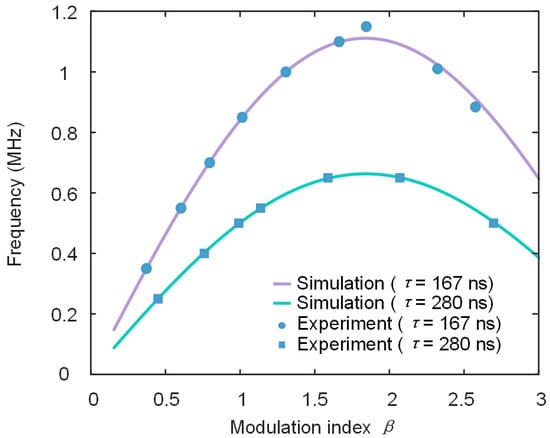
The relationship between the modulation index β and the oscillation frequency is also investigated. Figure 5 presents the evolution of the oscillation frequency as a function of the modulation index β for two distinct FSRs of 6 and 3.58 MHz, corresponding to round-trip times τ = 167 ns (lilac curves) and τ = 280 ns (olive curves), respectively. It can be seen from the solid lines in Figure 5 that as β increases, the oscillation frequency initially rises due to the stronger coupling strength κ, which scales with the first-order Bessel function J1(β) associated with phase modulation sidebands. The frequency reaches a maximum at approximately β = 1.85, beyond which further increase in β leads to a decline in the oscillation frequency. This suppression arises from the natural decay of J1(β) at higher modulation indices, which reduces the coupling strength κ and consequently reduces the frequency of oscillation. Experimental results are also measured, which are shown as the dotted lines in Figure 5. Excellent agreement between simulated and experimental results can be observed. Notably, the oscillation frequency closely follows the trend of the first-order Bessel function J1(β). When the modulation index crosses the first zero of J1(β), located at β ≈ 3.83, the effective coupling coefficient κ = J1(β)/τ changes sign. The measurable oscillation frequency is determined by |J1(β)|, whereas the sign reversal of J1(β) produces a π-phase shift in the oscillation relative to a fixed RF reference. This behavior enables a form of bipolar phase-frequency coding, where the frequency of the oscillation signal is a function of the RF signal amplitude, and the phase is inherently flipped at a specific modulation index.
Figure 5.
Simulated and experimental results to show the oscillation frequency as a function of the modulation index β, which is determined by the RF signal driving power. The lilac curve and the olive curve show the simulated oscillation frequencies when β increases, with two different round-trip times τ = 167 ns and τ = 280 ns, respectively. Dots show the data measured in the experiment, with round dots for τ = 167 ns and square dots for τ = 280 ns.
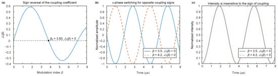
To further clarify the behavior beyond the experimentally accessible modulation-index range, Figure 6 presents a coupled-mode calculation across the first positive zero of J1(β), located at β0 = 3.83. As shown in Figure 6a, the signed coupling coefficient κ = J1(β)/τ changes from positive to negative when β crosses β0. Two representative modulation indices, β = 3.5 and β = 4.2, are selected on opposite sides of the zero. They correspond to nearly equal coupling magnitudes but opposite coupling signs. Under the resonant and balanced-gain conditions, the directly measured oscillation frequency is fosc = ∣J1(β)∣/(πτ); thus, the two cases have nearly identical oscillation frequencies. However, as shown in Figure 6b, the phase-sensitive field amplitudes exhibit a relative π-phase difference because the complex coupling coefficient changes sign. In contrast, the square-law detected intensity depends on the modulus squared of the field and is insensitive to the sign of κ. Consequently, the corresponding intensity traces overlap, as shown in Figure 6c. These results demonstrate that observation of the coupling-sign reversal requires a coherent phase-sensitive measurement relative to a fixed reference. The present experiment was limited to β approximately 3.1 and did not reach the first zero; no experimental phase-switching result is claimed.
Figure 6.
Predictive analysis across the first zero of J1(β). (a) The signed first-order Bessel coefficient; the first zero β0 marks reversal of the coupling sign. (b) Calculated normalized phase-sensitive field amplitudes for β = 3.5, where J1(β) > 0, and β = 4.2, where J1(β) < 0. (c) The corresponding normalized direct-detection intensities overlap.
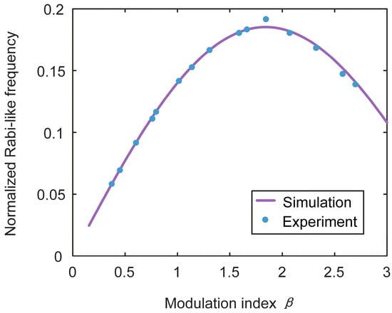
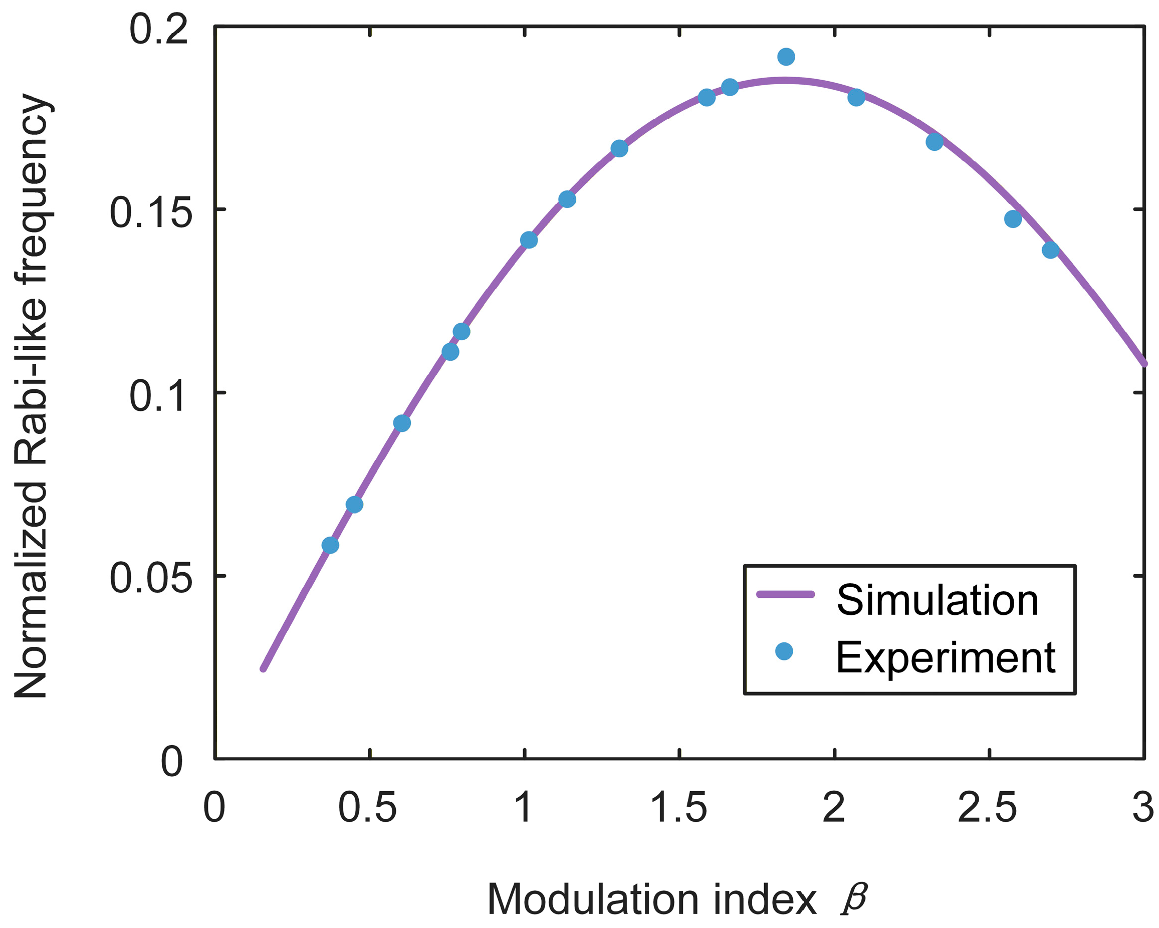
The relationship between the external RF signal power and the oscillation frequency for different round-trip times is evaluated to study the normalized Rabi-like frequency, which is defined as the ratio of the oscillation frequency to the FSR [32]. This dimensionless parameter effectively characterizes the normalized coupling strength within the system, analogous to the Rabi frequency normalized by the intrinsic time scale in an atomic system. Figure 7 illustrates the normalized Rabi-like frequency as a function of the modulation index β for two different round-trip times. As can be seen, the normalized Rabi-like frequency is independent of the round-trip time; instead, it is solely dictated by the modulation index. By analogy with atomic systems, where the Rabi frequency determines the rate of coherent population oscillations between energy states, the normalized Rabi-like frequency here represents the effective rate of energy exchange between the photonic ‘states’ (i.e., the wavelengths in the coupled laser loops). Maximizing the oscillation frequency in the proposed microwave photonic two-level system thus requires maximizing the normalized Rabi-like frequency. This condition is met when the modulation index is β ≈ 1.85, or the external RF signal voltage is about 60% of the half-wave voltage Vπ, which leads to the strongest coupling. Although the absolute oscillation frequency Ω scales with the inverse of the round-trip time τ, the normalized Rabi-like frequency fosc/FSR is independent of τ, depending only on the modulation index β. This allows for comparison across different systems regardless of their physical geometry. On the other hand, the absolute oscillation frequency is inversely proportional to the round-trip time τ; thus, to generate oscillations with a high frequency, a system with a small round-trip time or a large FSR is needed.
Figure 7.
Simulated and experimental results with normalized Rabi-like frequencies for different round-trip times, and it shows the dependence of the normalized Rabi-like frequency on the modulation index β, revealing a strong dependence on the first-order Bessel function J1(β). The simulated curve shows the relationship of the normalized Rabi-like frequency as β increases. Dots show the data measured in the experiment.
Based on the above discussion of the normalized Rabi-like oscillation frequency, under the condition of β ≈ 1.85, the maximum normalized Rabi-like oscillation frequency can exceed approximately 0.18, which means that the oscillation frequency of a system can exceed approximately 18% of its FSR. For example, using a similar configuration as [33], in which the FSR is 0.22 nm, could achieve a maximum oscillation frequency of fosc = 5 GHz, with frequency variation when tuning the input RF signal amplitude. The normalized Rabi-like frequency provides a geometry-independent way to characterize the RF-controlled coupling strength. If the same normalized scaling can be preserved in a short-cavity or integrated implementation, a larger FSR would allow proportionally higher oscillation frequencies. This extrapolation, however, requires future experimental verification. Overall, the results in Figure 7 demonstrate that the normalized Rabi-like frequency, defined as fosc/FSR, is solely dependent on the modulation index β, establishing a geometry-independent framework for characterizing the coupling dynamics in microwave photonic analogs of atomic systems.
At an FSR of 6 MHz, the measured oscillation frequency increases from 0.55 to 1.00 MHz when the input RF signal power increases from 11.7 to 18.7 dBm, following the dependence of J1(β). The experimental results for FSRs of 6 and 3.58 MHz also follow the inverse dependence on the round-trip time. The normalized frequency fosc/FSR mainly depends on β. These existing measurements support modulation-induced Rabi-like coupling in the near-resonant, short-time range investigated here; they are not a systematic detuning or long-term reliability test.
4. Discussion
The analogy used here is based on the equation of motion. The selected lasing modes at ω1 and ω2 form two effective photonic states, and their complex amplitudes A(t) and B(t) obey the coupled-mode equation. The reciprocal first-order sidebands generated by electro-optic phase modulation provide the coupling between the two modes. The RF frequency determines the detuning δ, while the RF voltage determines the modulation index β and the coupling strength κ = J1(β)/τ. Thus, the photonic system and a driven two-level system can show resonance-dependent oscillation described by the same reduced equation. However, the optical fields are classical, and the photodetected signals are optical intensities rather than quantum-state populations. The active cavities also contain gain, loss, feedback, technical noise, and residual longitudinal modes. Therefore, the observed behavior is a classical Rabi-like analog and is not a physical realization of quantum-state evolution.
The present system is based on two long fiber-ring cavities and may support multiple longitudinal modes. In the upper loop, the 200 MHz passband of the PS-FBG and the 6 MHz cavity FSR correspond to about 33 longitudinal resonance positions within the filter passband. This is a nominal estimate of the available resonances and is not the measured number of simultaneously lasing modes. The actual mode distribution depends on the filter response, round-trip loss, EDFA gain, gain saturation, and mode competition. A direct determination of the mode number requires a longitudinal-mode-resolved optical spectrum or electrical beat-spectrum measurement, which was not performed. Therefore, we state only that the PS-FBG suppresses non-primary modes rather than claiming stable single-longitudinal-mode operation.
The present discrete system was not optimized for long-term frequency or amplitude stability. The long fiber paths are sensitive to temperature change, mechanical vibration, and acoustic perturbation. Drift of the optical filters and the OTDL changes the detuning and round-trip-time matching between the loops. The polarization controller, fiber connections, EDFAs, and RF source introduce polarization, gain, intensity, and phase fluctuations. These effects contribute to differences between the measured and simulated waveforms and limit repeatability over long intervals. A future integrated implementation could reduce some of these effects: short cavities would increase the FSR and reduce the number of competing modes, while integrated paths, thermal tuning, power monitoring, and feedback could improve detuning and coupling control. Integration would not remove all thermal, laser, or RF-source noise, but it would provide a more compact platform for long-term measurements.
In an atomic two-level system, spontaneous emission produces population relaxation and decay of quantum coherence, while dephasing changes the relative phase of the states. The present microwave-photonic system does not reproduce these microscopic quantum processes. RF-source phase noise, optical-detuning drift, and polarization-dependent coupling introduce classical fluctuations in the phase and strength of the electro-optic interaction. Laser relative intensity noise and EDFA gain fluctuation change the amplitude and contrast, while residual longitudinal-mode beating and mode competition can distort the waveform. Over repeated measurements or long observation intervals, these perturbations can reduce the visibility and phase repeatability of the Rabi-like oscillation. This effect is phenomenologically similar to damping or dephasing, but it is not equivalent to spontaneous-emission-induced quantum decoherence. Since the individual noise contributions and corresponding coherence time were not measured separately, no quantitative T1- or T2-like parameter is assigned.
The present measurements demonstrate near-resonant, RF-power-dependent Rabi-like oscillation over short time windows. A systematic detuning map, long-term stability test, and statistical repeatability test were not performed and are left for future work. A short-cavity or integrated system with active detuning and power control would be more suitable for these measurements, although the remaining thermal, laser, and RF-source noise would still require characterization.
The present experiment implements one classical effective two-state unit. At the coupled-mode level, several units could be constructed by selecting multiple pairs of lasing modes in an active-loop or integrated resonator network. Independently controlled electro-optic coupling channels could then define the coupling matrix. Such a system could emulate collective exchange among several effective two-level subsystems if the mode frequencies, detuning, gain balance, filter selectivity, and coupling phases are controlled. Direct scaling of the fiber system would increase environmental and multimode sensitivity; an integrated platform with tunable couplers, thermal control, and on-chip monitoring would be more suitable. This extension would remain a classical dynamical emulator. Classical coherent fields do not generate genuine quantum entanglement or nonclassical correlations. An entangled multi-qubit system would additionally require nonclassical states, quantum-coherent preparation and operation, and quantum-state-resolved measurements.
5. Conclusions
A microwave-photonic two-state analog based on two active fiber loops has been experimentally demonstrated. Two selected lasing modes form the effective states, while reciprocal electro-optic sidebands provide the coupling. For an FSR of 6 MHz, the measured oscillation frequency is tuned from 0.55 to 1.00 MHz by increasing the RF power from 11.7 to 18.7 dBm, consistent with the coupled-mode model. The experiment demonstrates near-resonant, short-time Rabi-like oscillatory exchange in a classical active-loop system. It does not reproduce quantum-state populations, spontaneous-emission dynamics, or entanglement, and the present long-cavity implementation is limited by residual multimode operation and environmental sensitivity.
To further characterize this behavior, we introduced the concept of normalized Rabi-like frequency, defined as the ratio of the oscillation frequency to the FSR. This dimensionless parameter provides a normalized measure of coupling strength and is notably independent of the FSR, making it a robust metric for dynamic frequency control. The normalized Rabi-like frequency provides a geometry-independent metric for characterizing RF-controlled coupling strength. Although the present fiber-loop implementation is not optimized for stable RF signal generation, the observed scaling provides useful guidance for future short-cavity or integrated implementations of active photonic coupling systems.
Author Contributions
Conceptualization, Z.S. and S.D.; methodology, Z.S.; software, Z.S. and S.D.; validation, Z.S. and S.D.; formal analysis, Z.S.; investigation, Z.S. and S.D.; resources, Z.S.; data curation, Z.S.; writing—original draft preparation, Z.S. and S.D.; writing—review and editing, Z.S., S.D., Y.H., J.W. (Junqi Wang), J.S., J.W. (Jianghai Wo), X.W., J.Z. and J.Y.; visualization, Z.S. and S.D.; supervision, X.W., J.Z. and J.Y.; project administration, X.W., J.Z. and J.Y.; funding acquisition, J.W. (Junqi Wang), J.S., J.W. (Jianghai Wo), X.W., J.Z. and J.Y. All authors have read and agreed to the published version of the manuscript.
Funding
This research was funded by the National Key Research and Development Program of China under Grant No. 2024YFB2807400, by the Guangdong Basic and Applied Basic Research Foundation under Grant No. 2025A1515010703, and by the National Undergraduate Training Program for Innovation and Entrepreneurship under Grant No. 202610559107.
Institutional Review Board Statement
Not applicable.
Informed Consent Statement
Not applicable.
Data Availability Statement
The raw data supporting the conclusions of the article will be made available by the authors upon request.
Conflicts of Interest
The authors declare no conflicts of interest.
References
- Rabi, I.I. Space quantization in a gyrating magnetic field. Phys. Rev. 1937, 51, 652–654. [Google Scholar] [CrossRef] [Scilit]
- Allen, L.; Eberly, J.H. Optical Resonance and Two-Level Atoms; Dover Publications: New York, NY, USA, 1987. [Google Scholar]
- Ozdemir, S.K.; Rotter, S.; Nori, F.; Yang, L. Parity-time symmetry and exceptional points in photonics. Nat. Mater. 2019, 18, 783–798. [Google Scholar] [CrossRef] [Scilit] [PubMed]
- Regensburger, A.; Bersch, C.; Miri, M.-A.; Onishchukov, G.; Christodoulides, D.N.; Peschel, U. Parity–time synthetic photonic lattices. Nature 2012, 488, 167–171. [Google Scholar] [CrossRef] [Scilit] [PubMed]
- Dai, T.; Ma, A.; Mao, J.; Ao, Y.; Jia, X.; Zheng, Y.; Zhai, C.; Yang, Y.; Li, Z.; Tang, B.; et al. A programmable topological photonic chip. Nat. Mater. 2024, 23, 928–936. [Google Scholar] [CrossRef] [Scilit] [PubMed]
- Lu, L.; Joannopoulos, J.D.; Soljačić, M. Topological photonics. Nat. Photon. 2014, 8, 821–829. [Google Scholar] [CrossRef] [Scilit]
- Dutt, A.; Mohanty, A.; Gaeta, A.L.; Lipson, M. Nonlinear and quantum photonics using integrated optical materials. Nat. Rev. Mater. 2024, 9, 321–346. [Google Scholar] [CrossRef] [Scilit]
- Elshaari, A.W.; Pernice, W.; Srinivasan, K.; Benson, O.; Zwiller, V. Hybrid integrated quantum photonic circuits. Nat. Photon. 2020, 14, 285–298. [Google Scholar] [CrossRef] [Scilit] [PubMed]
- Capmany, J.; Novak, D. Microwave photonics combines two worlds. Nat. Photon. 2007, 1, 319–330. [Google Scholar] [CrossRef] [Scilit]
- Marpaung, D.; Yao, J.; Capmany, J. Integrated microwave photonics. Nat. Photon. 2019, 13, 80–90. [Google Scholar] [CrossRef] [Scilit]
- Yao, J.; Capmany, J. Microwave photonics. Sci. China Inf. Sci. 2022, 65, 221401. [Google Scholar] [CrossRef] [Scilit]
- Yao, X.S.; Maleki, L. Optoelectronic microwave oscillator. J. Opt. Soc. Am. B 1996, 13, 1725–1735. [Google Scholar] [CrossRef] [Scilit]
- Maleki, L. The optoelectronic oscillator. Nat. Photon. 2011, 5, 728–730. [Google Scholar] [CrossRef] [Scilit]
- Pan, S.; Zhang, Y. Microwave photonic radars. J. Light. Technol. 2020, 38, 5450–5484. [Google Scholar] [CrossRef] [Scilit]
- Parriaux, A.; Hammani, K.; Millot, G. Electro-optic frequency combs. Adv. Opt. Photon. 2020, 12, 223–287. [Google Scholar] [CrossRef] [Scilit]
- Zhang, M.; Buscaino, B.; Wang, C.; Shams-Ansari, A.; Reimer, C.; Zhu, R.; Kahn, J.M.; Lončar, M. Broadband electro-optic frequency comb generation in a lithium niobate microring resonator. Nature 2019, 568, 373–377. [Google Scholar] [CrossRef] [Scilit] [PubMed]
- Zhang, J.; Yao, J. Parity-time–symmetric optoelectronic oscillator. Sci. Adv. 2018, 4, eaar6782. [Google Scholar] [PubMed]
- Li, P.; Dai, Z.; Fan, Z.; Yan, L.; Yao, J. Parity-time-symmetric frequency-tunable optoelectronic oscillator with a single dual-polarization optical loop. Opt. Lett. 2020, 45, 3139–3142. [Google Scholar] [CrossRef] [Scilit] [PubMed]
- Qiao, Y.; Zhang, Y.; Zheng, R.; Chan, E.H.W.; Wang, X.; Feng, X.; Guan, B.O.; Yao, J. Parity-time-symmetric optoelectronic oscillator based on higher-order optical modulation. Opt. Lett. 2022, 47, 4383–4386. [Google Scholar] [CrossRef] [Scilit] [PubMed]
- Caselli, N.; Intonti, F.; La China, F.; Biccari, F.; Riboli, F.; Gerardino, A.; Li, L.; Linfield, E.H.; Pagliano, F.; Fiore, A.; et al. Generalized Fano lineshapes reveal exceptional points in photonic molecules. Nat. Commun. 2018, 9, 396. [Google Scholar] [CrossRef] [Scilit] [PubMed]
- Helgason, Ó.B.; Arteaga-Sierra, F.R.; Ye, Z.; Twayana, K.; Andrekson, P.A.; Karlsson, M.; Schröder, J.; Torres-Company, V. Dissipative solitons in photonic molecules. Nat. Photon. 2021, 15, 305–310. [Google Scholar] [CrossRef] [Scilit]
- Tao, Z.; Shen, B.; Li, W.; Xing, L.; Wang, H.; Wu, Y.; Tao, Y.; Zhou, Y.; He, Y.; Peng, C.; et al. Versatile photonic molecule switch in multimode microresonators. Light Sci. Appl. 2024, 13, 51. [Google Scholar] [CrossRef] [Scilit] [PubMed]
- Yuan, L.; Lin, Q.; Xiao, M.; Fan, S. Synthetic dimension in photonics. Optica 2018, 5, 1396–1405. [Google Scholar] [CrossRef] [Scilit]
- Englebert, N.; Goldman, N.; Erkintalo, M.; Mostaan, N.; Gorza, S.-P.; Leo, F.; Fatome, J. Bloch oscillations of coherently driven dissipative solitons in a synthetic dimension. Nat. Phys. 2023, 19, 1014–1021. [Google Scholar] [CrossRef] [Scilit]
- Guan, Y.; Zhang, J.; Li, L.; Cao, R.; Wang, G.; Chen, J.; Wang, X.; Guan, B.-O.; Yao, J. Tera-sample-per-second arbitrary waveform generation in a synthetic dimension. Commun. Phys. 2023, 6, 258. [Google Scholar] [CrossRef] [Scilit]
- Spreeuw, R.J.; van Druten, N.J.; Beijersbergen, M.W.; Eliel, E.R.; Woerdman, J.P. Classical realization of a strongly driven two-level system. Phys. Rev. Lett. 1990, 65, 2642–2645. [Google Scholar] [CrossRef] [Scilit] [PubMed]
- Faust, T.; Rieger, J.; Seitner, M.J.; Kotthaus, J.P.; Weig, E.M. Coherent control of a classical nanomechanical two-level system. Nat. Phys. 2013, 9, 485–488. [Google Scholar] [CrossRef] [Scilit]
- Zhang, M.; Wang, C.; Hu, Y.; Shams-Ansari, A.; Ren, T.; Fan, S.; Lončar, M. Electronically programmable photonic molecule. Nat. Photon. 2019, 13, 36–40. [Google Scholar] [CrossRef] [Scilit]
- Haus, H.A.; Huang, W. Coupled-mode theory. Proc. IEEE 1991, 79, 1505–1518. [Google Scholar] [CrossRef] [Scilit]
- Fujii, K. Introduction to the rotating wave approximation (RWA): Two coherent oscillations. J. Mod. Phys. 2017, 8, 2042–2058. [Google Scholar]
- Autler, S.H.; Townes, C.H. Stark effect in rapidly varying fields. Phys. Rev. 1955, 100, 703–722. [Google Scholar] [CrossRef] [Scilit]
- Sato, Y.; Tanaka, Y.; Upham, J.; Takahashi, Y.; Asano, T.; Noda, S. Strong coupling between distant photonic nanocavities and its dynamic control. Nat. Photon. 2012, 6, 56–61. [Google Scholar] [CrossRef] [Scilit]
- Liu, W.; Li, M.; Guzzon, R.S.; Norberg, E.J.; Parker, J.S.; Lu, M.; Coldren, L.A.; Yao, J. An integrated parity-time symmetric wavelength-tunable single-mode microring laser. Nat. Commun. 2017, 8, 15389. [Google Scholar] [CrossRef] [Scilit] [PubMed]

Disclaimer/Publisher’s Note: The statements, opinions and data contained in all publications are solely those of the individual author(s) and contributor(s) and not of MDPI and/or the editor(s). MDPI and/or the editor(s) disclaim responsibility for any injury to people or property resulting from any ideas, methods, instructions or products referred to in the content. |
© 2026 by the authors. Licensee MDPI, Basel, Switzerland. This article is an open access article distributed under the terms and conditions of the Creative Commons Attribution (CC BY) license.