


Abstract
The illumination system in extreme ultraviolet lithography (EUVL) achieves pupil shaping by adjusting the facet-matching relationship of fly’s eyes. We propose an algorithm based on integer programming and energy equalization for solving the facet-matching relationship, which constrains the energy consistency across different pupil regions, enhancing pupil performance and achieving high uniformity at the mask plane. We model an illumination system to validate the proposed algorithm. Simulation results demonstrate that the proposed algorithm successfully realizes various illumination modes, achieving a maximum pupil ellipticity of 1.94%, maximum X/Y pupil pole balance of 1.45%, and maximum quadrant pole balance of 1.82%. Furthermore, it achieved an illumination field at the mask plane with a pre-correction nonuniformity of 0.45–0.59%.
1. Introduction
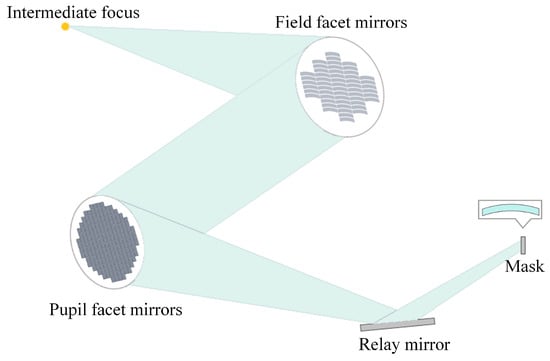
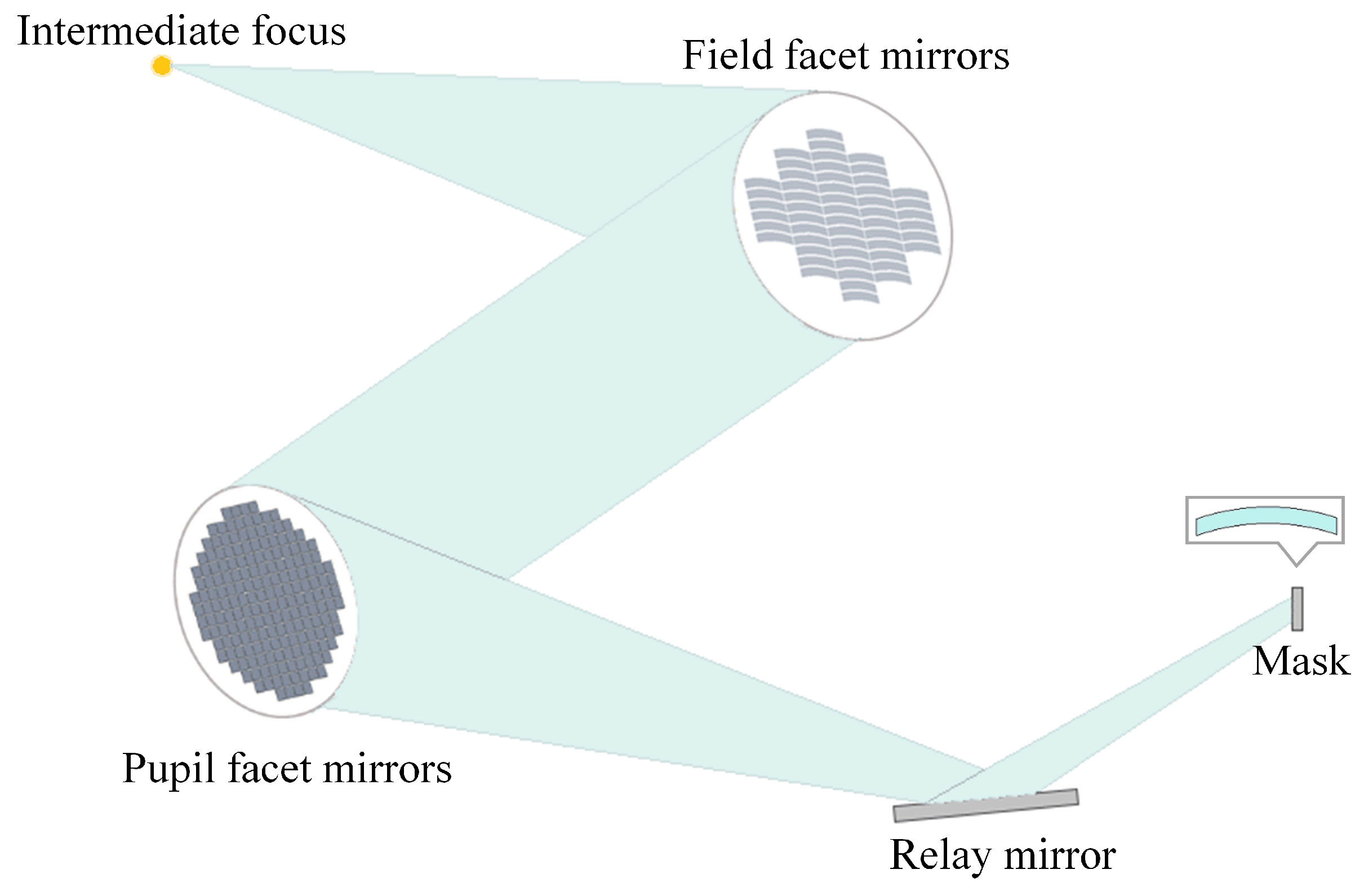
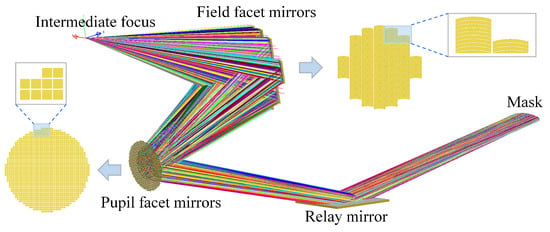
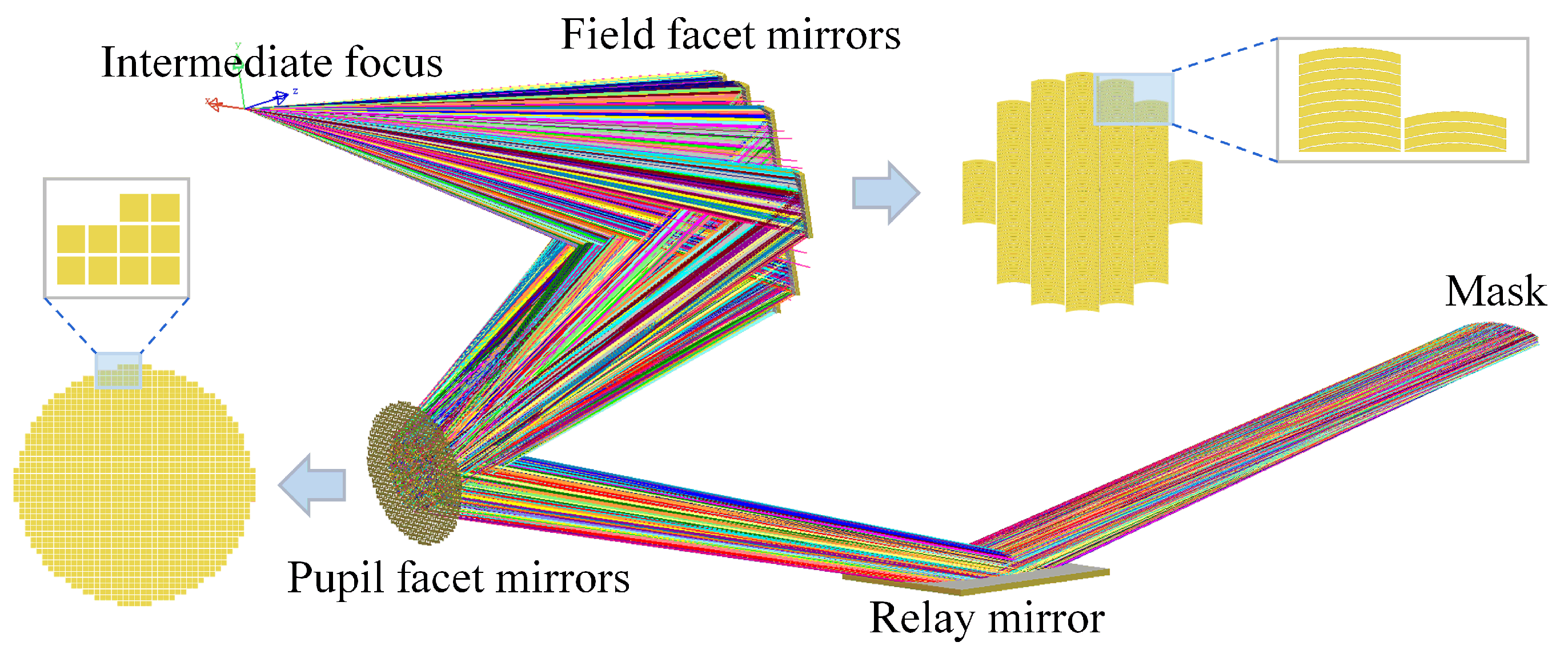
Integrated circuits are the cornerstone of modern electronic technology. According to Moore’s law, the integration density of integrated circuits quadruples every three years, while a critical dimension (CD) is halved every three years [1,2,3]. As the CD of circuit patterns continues to shrink, extreme ultraviolet (EUV) lithography significantly reduces the exposure wavelength to 13.5 nm. This enables the patterning of smaller CD with reduced complexity in projection lens design under more relaxed processing conditions [4,5,6]. The illumination system in EUV lithography employs a reflective double facet mirror structure to achieve pupil shaping [7]. As illustrated in Figure 1, this system comprises numerous fly’s eyes categorized into two types: field facet mirrors (FFMs) and pupil facet mirrors (PFMs). Various off-axis illumination modes required for resolution enhancement techniques can be realized by altering the facet-matching relationship between the FFMs and PFMs [8,9]. Therefore, determining the facet-matching relationship of the fly’s eyes is a critical issue in pupil-shaping technology for implementing different illumination modes.
Figure 1.
Schematic of the EUVL illumination system. The illumination system consists of an intermediate focus (IF) point, FFMs, PFMs, relay mirror and mask. By adjusting the facet-matching relationship of the fly’s eyes, it achieves various illumination modes at the exit pupil and forms a uniform illumination field at the mask plane.
For solving the facet-matching relationship, existing methods involve partitioning FFMs and PFMs into regions, where matching between different regions is performed based on the proximity principle to reduce the mirror rotation angle of the FFMs. Common partitioning strategies divide the entire field facet mirror (FFM) and pupil facet mirror (PFM) arrays into three regions (top, middle, and bottom) or four quadrants such that FFMs in a corresponding region match exclusively with the nearest PFMs in the same region [10,11,12]. Although this approach reduces the computational complexity of solving the facet-matching relationship by narrowing the selection scope during FFM–PFM matching, the constraint of matching fixed partitions simultaneously reduces the solution space of the problem. This limitation degrades the quality of the obtained solution, adversely affecting the performance of the pupil of the EUVL illumination system, such as ellipticity and pole balance.
We depart from the conventional method of partitioning and proximity-based matching of FFMs and PFMs. Instead, we first propose a label classification strategy, whereby the facet-matching relationship of fly’s eyes can be solved using integer programming and an energy equalization algorithm. Subsequently, we model the illumination system using the LightTools (2023.03) software to verify the effectiveness of the proposed algorithm by simulating the illumination field and pupil. Finally, we perform a tolerance analysis by introducing positional errors to the FFMs and PFMs in the illumination system to verify the robustness of the proposed algorithm.
2. Methods
2.1. Algorithm Input
There are seven commonly used illumination modes in EUVL: conventional, small annular, large annular, X dipole, Y dipole, 0° quadrupole, and 45° quadrupole [13,14,15]. Two relatively extreme coherence factors were selected for each mode to validate the effectiveness of the proposed algorithm. The parameters for the 14 illumination modes used in this study are listed in Table 1 [11].
Table 1.
Parameter settings for 14 illumination modes.
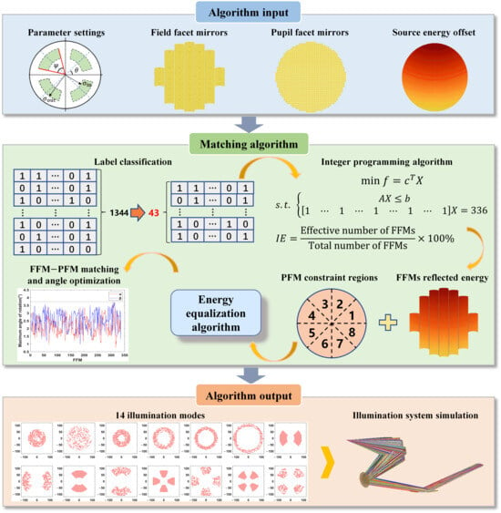
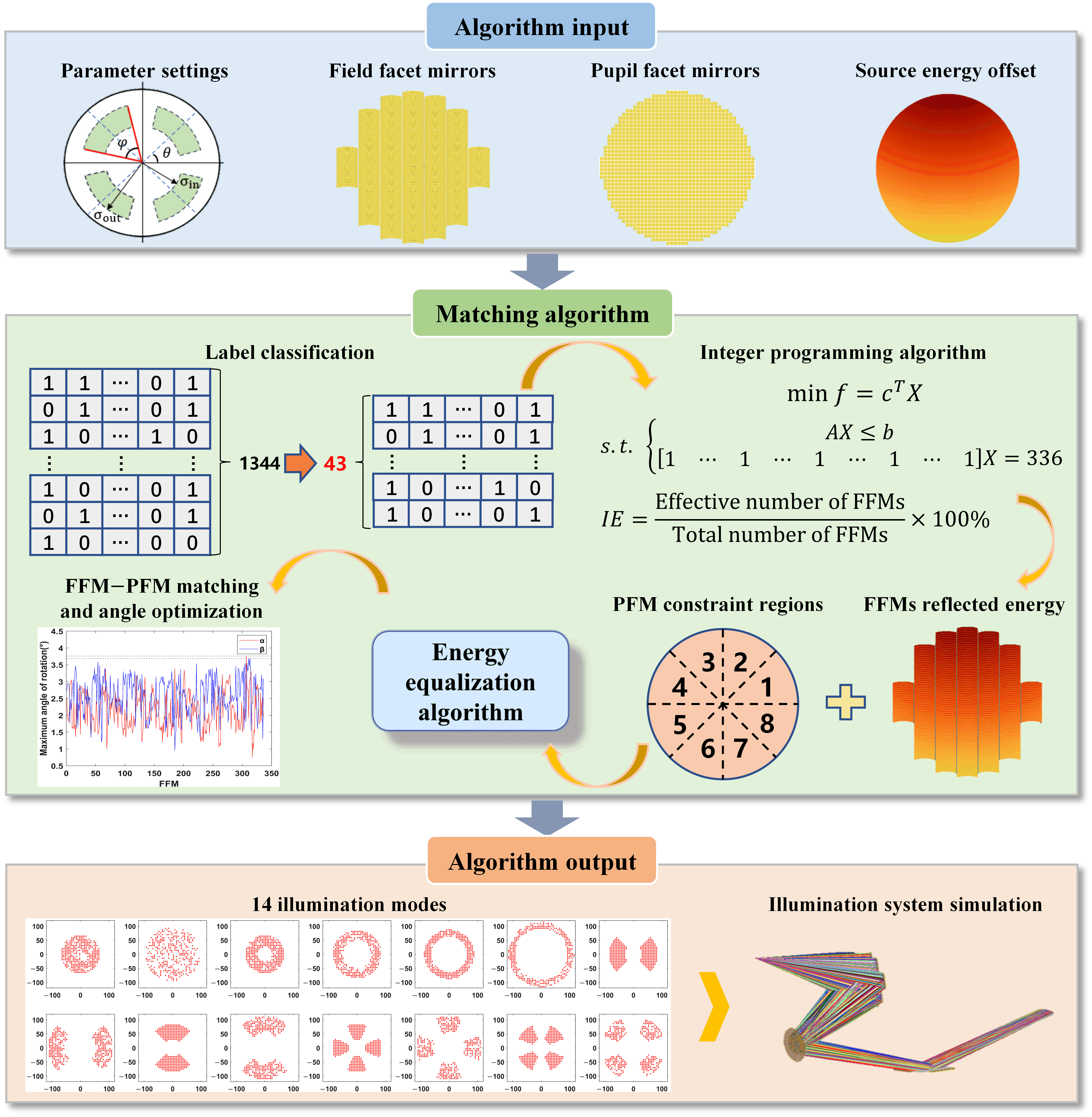
In EUVL illumination systems, the quantity of PFMs is at least twice that of FFMs to achieve various illumination modes at the exit pupil [16]. Accordingly, in our algorithm design, the number of FFMs was set to 336, and the number of PFMs to 1344 [17]. We introduced illumination efficiency (IE) as a critical constraint to enhance energy utilization. IE is defined as the ratio of the number of effectively used FFMs to the total number of FFMs for each illumination mode. The term “effectively used” confirms that the light emitted from the intermediate focus (IF) point is reflected by the FFMs, PFMs, and relay mirror to reach the effective area of the illumination field on the mask plane. Ensuring 100% utilization of the FFMs minimizes unnecessary energy loss during the design phase. Increasing the power of EUV sources can effectively boost throughput [18,19,20]; however, achieving such power increases remains technically challenging and improving energy utilization under limited power conditions is of paramount importance. In this context, enhancing IE significantly optimizes the energy utilization of EUV sources. A flowchart of the designed algorithm based on the aforementioned inputs is shown in Figure 2.
Figure 2.
Algorithm flowchart. Taking the pupil parameters of various illumination modes, FFMs and PFMs coordinates, and the source’s far-field energy distribution as inputs, the algorithm first applies label classification to reduce computational complexity. Subsequently, an integer programming algorithm is utilized to identify label combinations satisfying the 100% illumination efficiency (IE). Based on the source’s far-field energy, the reflected energy of individual FFMs is calculated. By integrating the PFM quantity constraints across different pupil regions, an energy equalization algorithm is applied to group the FFMs. Finally, after performing FFM-PFM matching and angle optimization, the algorithm outputs the facet-matching relationships for each mode, which are subsequently modeled and simulated in LightTools.
2.2. Matching Algorithm
Solving the facet-matching relationship of the fly’s eyes under different modes is a discrete optimization problem. In general, heuristic or exact algorithms are employed to approximate optimal solutions for such problems. Heuristic algorithms such as simulated annealing (SA) and genetic algorithms (GAs) are suitable for multi-objective optimization and easy to implement; however, their search capability is limited. In contrast, exact algorithms such as the branch-and-bound method can find a precise global optimal solution; however, they have high computational complexity. The problem of solving the facet-matching relationship of the fly’s eyes involves ultra-large-scale integer variables and constraints with coupling effects between them, making it an NP-hard problem.
Heuristic algorithms have previously been used to solve facet-matching relationships. The objective function was constructed using the IE constraints and pupil performance parameters, taking the form shown in Equation (1). Here, and represent the penalty function for the IE constraints and the penalty function for the pupil ellipticity and pole balance; represents the weighting factor for IE; and represents the weighting factor related to the requirements of the pupil performance indicators. When applying the algorithm, increasing the weight of the pupil performance indicators can improve the pupil performance. However, with improvements in pupil performance, it becomes difficult to guarantee 100% IE realization, leading to a decrease in the energy utilization rate of the system. Furthermore, the algorithm tends to become trapped in local optima.
This problem is modeled as a pure integer programming (IP) problem. Unlike heuristic algorithms that can terminate at a local optimum, IP conducts a complete and systematic enumeration of the integer feasible region through a branch-and-bound framework. Further, it utilizes the lower bound provided by the linear relaxation for pruning, ensuring that the final integer solution obtained is globally optimal. Moreover, introducing the label classification concept can effectively reduce the scale of data processing, lowering the computational complexity of the algorithm.
2.2.1. Label Classification and Grouping
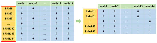
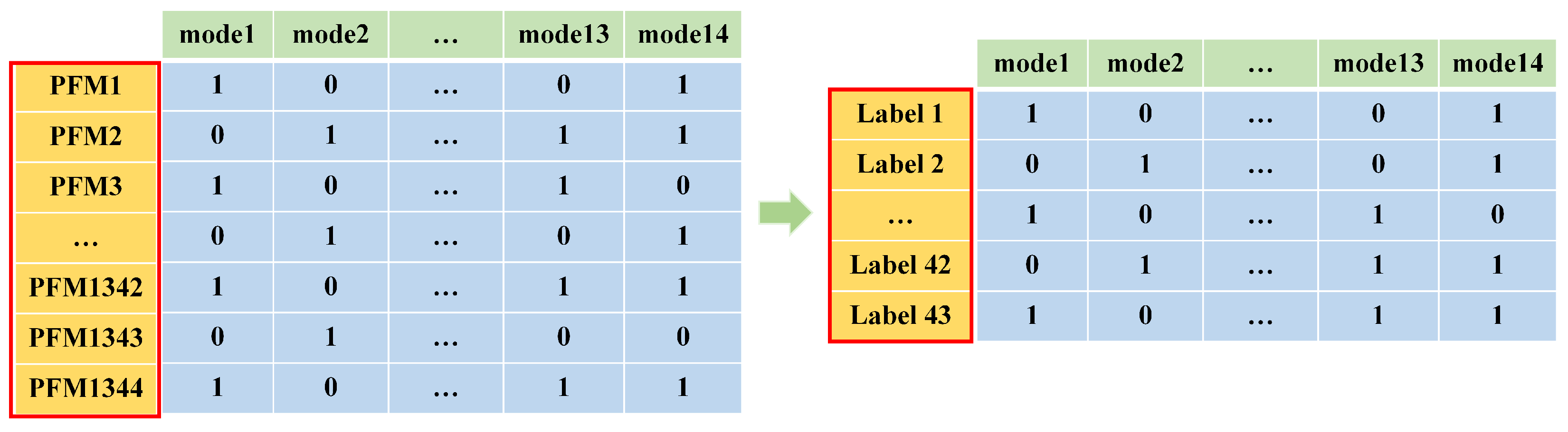
Based on the usage of PFMs across 14 illumination modes, a 1344 × 14 binary matrix (0–1 matrix) was generated. Each column of the matrix represents PFMs used in a specific illumination mode, whereas each row represents the usage status of an individual PFM across different modes, where “1” indicates “used,” and “0” indicates “unused”. We propose a label classification concept to reduce the complexity of the problem grouping and ensure that the subsequent process satisfies the IE constraint. The labels corresponding to the 1344 PFMs can be categorized into 43 distinct types by treating each row of the aforementioned matrix as a label. Consequently, the 1344 × 14 matrix is simplified to a 43 × 14 matrix as shown in Figure 3. This significantly reduces the complexity of data processing, and a 100% IE constraint can be achieved in the next step by combining different types of labels.
Figure 3.
Label classification of the PFMs.
Four distinct label types were selected from the 43 candidates to create a label combination. After calculating all possible combinations, we filtered those that satisfied the 100% IE requirement. For example, the combination of Labels 1–4, as expressed in Equations (2)–(5), satisfies the 100% IE condition: the usage of PFMs corresponding to these four labels covers all illumination modes. This ensures that the matched FFM is utilized across all modes, guaranteeing 100% IE. Based on the aforementioned label classification results, the grouping complexity of the problem is reduced from to , facilitating the use of integer-programming algorithms for solving the solution space of label combinations.
Label 1: [1,0,0,1,1,0,0,0,0,1,0,0,1,0],
Label 2: [0,1,0,0,0,1,0,0,1,0,1,0,1,0],
Label 3: [0,1,0,1,0,0,1,0,1,0,0,1,0,1],
Label 4: [0,0,1,0,1,0,0,1,0,0,1,0,0,0].
After obtaining 100% IE label combinations, 336 combinations corresponding to the 336 FFMs were selected for the subsequent matching of the FFMs and PFMs. Integer programming was employed to solve this problem because the number of label combinations to be determined involves integer variables. Let b represent the number of PFMs corresponding to each label, represented as a 43-dimensional column vector, and let X represent the usage count of each label combination, represented as a 48,495 × 1 column vector. The obtained label combinations were transformed into a binary matrix A with dimensions 43 × 48,495. Each column of the matrix represents the usage status of the 43 labels within a specific label combination, whereas each row indicates the usage status of a specific label across all obtained label combinations. indicates that the j-th label combination contains the i-th label, and indicates its absence. c represents a column vector with the same dimensions as X, with all elements equal to 1. Therefore, the objective function and constraints for integer programming are formulated as
We can obtain the solution space of the label combinations that satisfy 100% IE by inputting the model into the solver. MATLAB (R2018b)’s intlinprog function is used as the solver, and it demonstrates a fast execution speed. Furthermore, it updates the absolute and relative gaps in real-time during the solution process. The solution returned by the solver is guaranteed to be a globally optimal integer when the gap converges to zero.
2.2.2. Label Replacement and FFM Grouping
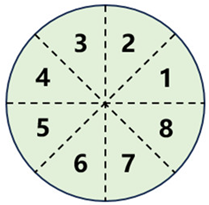
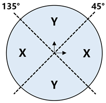
Minimizing energy discrepancies across different regions of the pupil is essential for achieving high pupil quality. The energy difference between the corresponding regions of the PFM array can be effectively constrained because the exit pupil of the illumination system is conjugated to the PFM array. Given that the energy distributions of the 14 illumination modes discussed in this study are either circular or segmented, the PFM array is divided into eight regions. Regional partitioning for the energy constraints across various illumination modes is presented in Table 2. Both label replacement and FFM grouping are necessary for constraining the energy discrepancies between the different regions of the PFM array. Label replacement involves replacing the labels in previously obtained 100% IE combinations with specific PFMs to ensure that the number of PFMs in each region is consistent. As the energy of the PFMs originates from the FFMs, the FFMs must be grouped to constrain the energy differences between these groups. An energy equalization algorithm is employed for grouping the FFMs. Based on the far-field energy differences received by the FFMs and the number of PFMs in different regions, the FFMs are grouped to minimize the energy sum differences between groups. The number of FFMs in each group must match the number of PFMs in the corresponding regions after label replacement to facilitate subsequent FFM-PFM matching.
Table 2.
Energy constraint of PFM regions in each mode.
Labels within the aforementioned 100% IE-satisfying combinations were replaced with distinct PFMs. The number of PFMs allocated to each region under a given illumination mode must be balanced to minimize the energy differences across the different regions of the PFM array. Two perturbation strategies were introduced to achieve this balance:
- Swapping PFMs corresponding to the same label across different label combinations.
- Swapping PFMs corresponding to different labels within the same label combination.
These perturbations did not compromise the 100% IE constraint, and through this process, the specific PFMs utilized for each illumination mode were determined.
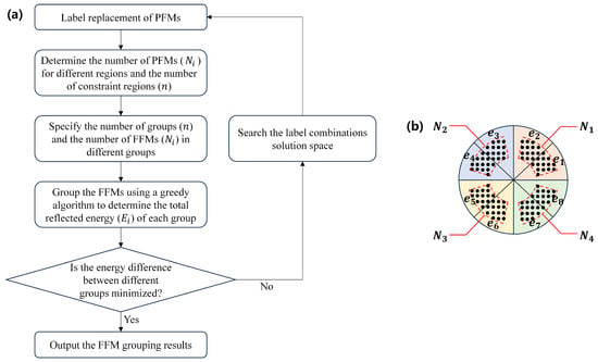
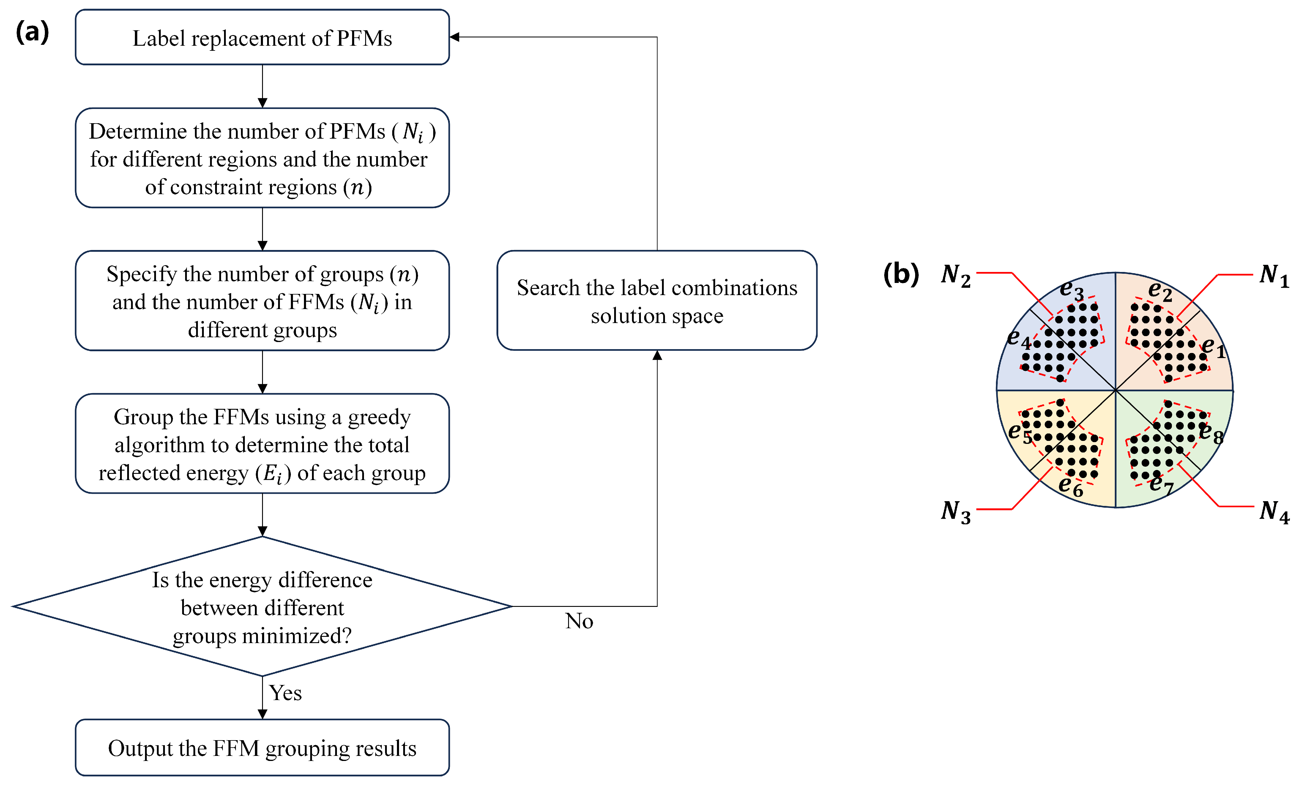
As the exit pupil of the illumination system is conjugated to the PFM array, the pupil performance can be improved by minimizing the energy differences across different regions of the PFM array. Since the energy on the PFM array is derived from the reflection of the source energy by the FFMs, the FFMs can be grouped based on their reflected energy. Each FFM group corresponds to the PFMs of a specific region on the PFM array. By minimizing the energy difference between different groups, the energy variation across different regions on the PFM array is effectively constrained, thereby ensuring high pupil quality. The flowchart of the energy equalization algorithm is shown in Figure 4a. Taking the 45° quadrupole illumination mode as an example, the application process of the energy equalization algorithm is illustrated. The PFMs utilized under this illumination mode are obtained through label replacement. The number of PFMs in different regions is , , , and , respectively, as shown in Figure 4b. To improve the pupil performance under this mode, the energy of its four regions (, , , ) must be constrained to be uniform according to Table 2. Therefore, the 336 FFMs are divided into four groups. To ensure 100% IE, a one-to-one correspondence between the FFMs and PFMs is required; thus, the number of FFMs in each group is also set to , , , and . By constructing the objective function shown in Equation (8), the difference in the energy reflected by FFMs among different groups is minimized, where represents the number of FFM groups under this mode, which is numerically equal to the number of constrained regions in Table 2. Under the 45° quadrupole illumination mode, the number of groups is 4. Let represent the total far-field energy of the light source reflected by all FFMs. denotes the total energy reflected by the FFMs in each group. For instance, under 45° quadrupole illumination mode, , , , and .
Figure 4.
Energy equalization algorithm description. (a) Flowchart of the energy equalization algorithm; (b) number of PFMs and energy in different regions of 45° quadrupole illumination mode. The red dashed areas in the figure represent the number of PFMs in different regions, while the black dots are the images of the IF point on the PFMs, which are conjugate to the pupil points of the exit pupil.
The FFM grouping problem described above is a balanced partitioning problem. The greedy algorithm is widely adopted as an efficient strategy for solving this problem; it involves sorting the data in descending order and assigning each item to the group with the current minimum sum [21,22,23]. Following this principle, we sort the energy reflected by individual FFMs in descending order and allocate FFMs based on the number of groups and the required number of FFMs per group. This approach minimizes the difference in total energy among the different FFM groups. Subsequently, we search within the solution space of label combinations, repeating the aforementioned label replacement and FFMs grouping steps until the optimal result is obtained, which minimizes the energy difference among different FFM groups. This algorithm can effectively suppress, to a certain extent, the far-field energy fluctuations or non-uniform distribution of the light source.
2.2.3. FFM–PFM Matching and Angle Optimization
Following label replacement and FFMs grouping, FFM–PFM matching is required for each mode. During the matching, the mirror rotation angle required for FFMs to align with PFMs is a primary consideration. The sequence of mirrors within the groups is swapped to optimize this FFM rotation angle with the objective of minimizing the total rotation angle required for each FFM to match its corresponding PFM. This optimization is necessary because minimizing the mirror rotation angle reduces the complexity of the mechanical design and control of the FFMs during actual operation.
During angle optimization, an integer-programming algorithm can be employed to solve the problem because the optimization variables, the sequence of mirrors within the same group, are integers. First, an angle matrix is established, where represents the number of FFMs (PFMs) within the group. The element represents the mirror rotation angle required for the i-th FFM to match the j-th PFM. Subsequently, the transpose of , represented as , is reshaped into an column vector referred to as c. Let represent the selection index vector indicating the matched PFMs for each FFM; it is an column vector with entries constrained to the range [0, 1], where “1” indicates the selection of the corresponding PFM and “0” indicates the nonselection. An binary matrix is constructed to ensure that each FFM matches exclusively with one PFM. The elements in the i-th row of matrix A are set to 1 within fixed columns, specifically . Furthermore, is defined as an column vector with all elements equal to 1. An binary matrix is created to guarantee that each PFM is selected only once; this includes identity matrices of order . Correspondingly, is defined as an column vector with all elements equal to 1. The objective function and constraints for the integer programming algorithm are formulated as
The facet-matching relationship for the group after angle optimization can be obtained by inputting these parameters into the solver. This method is applied to perform angle optimization and FFM-PFM matching for all groups, and the aforementioned steps are repeated to complete the facet-matching relationship for each mode. Considering FFM197 as an example, the angle-optimization results confirm that the maximum mirror rotation angle of the FFM across all illumination modes can be reduced by 57.72% after optimization, which demonstrates the effectiveness of the proposed algorithm.
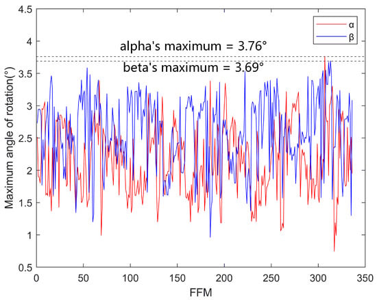
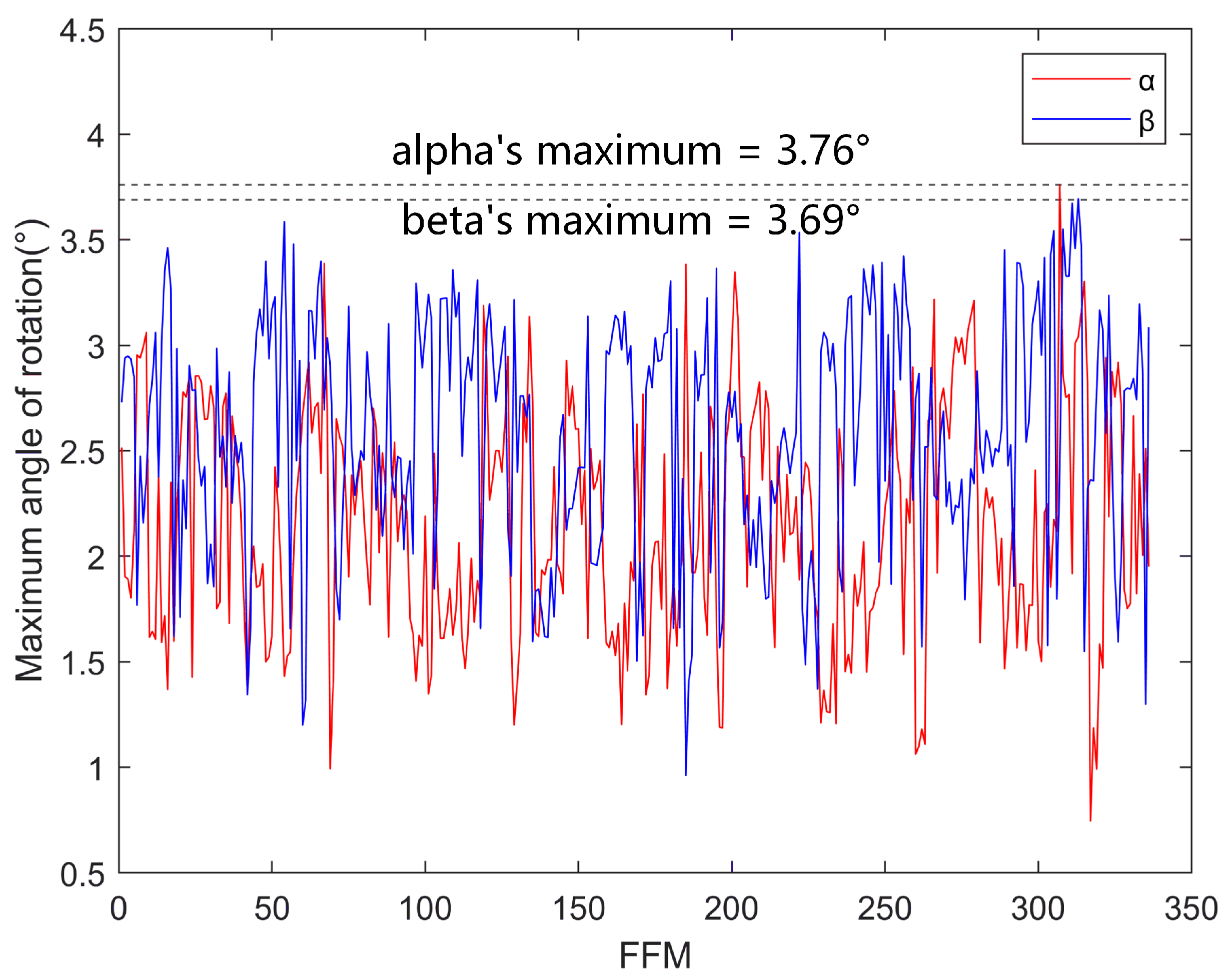
The optimized angle refers to the spatial rotation angle of the normal vector of the mirror to facilitate the construction of the objective function and enable the use of integer programming for angle optimization and FFM-PFM matching. Further, we decompose this deflection angle into and angles (where and represent the pitch and yaw angles of the FFM rotating around the X-axis and Y-axis of its local coordinate system, respectively). We find that the maximum total travel range for and deflection is 3.76° and 3.69°, respectively, across all matching scenarios, as shown in Figure 5. Moreover, adjusting the arrangement angle of the FFMs during the optical-path design phase can further minimize the mirror rotation angles. Smaller mirror deflection angles enable the actuators used for the FFMs to achieve a higher adjustment resolution and precision. Simultaneously, it reduces the load on the actuators, enabling them to deliver better control performance, which ultimately enhances their operational stability.
Figure 5.
FFM maximum rotation angle travel.
3. Results and Discussion
3.1. Simulation Configuration
3.1.1. Illumination System Modeling
We used LightTools software to model the optical path of the illumination system and incorporated the calculated facet-matching relationships into the model to verify the effectiveness of the proposed algorithm. Figure 6 illustrates the optical path model of the illumination system, where the light source is placed at the IF point, and all FFMs and PFMs are closely arranged within a circular area [11,24]. The clear aperture of the FFM is designed with an arc shape with dimensions of 55 mm × 5 mm to form the arc-shaped illumination field on the mask plane [6,11]. The clear aperture of the PFM is generally rectangular or circular [24]. In our simulation, we used a rectangular clear aperture with dimensions of 5 mm × 5 mm [11].
Figure 6.
Optical model of the illumination system in LightTools.
3.1.2. Ray Count Setting
The LightTools software employs Monte Carlo ray tracing. The ray count was analyzed before evaluating the illumination field and pupil performance to determine a reasonable number of rays for the simulation to ensure the accuracy and validity of the simulation results. Two illumination modes, small annular 1 and large annular 1, were selected for this test. The ray counts were set to 100 million, 200 million, 500 million, 700 million, 1 billion, 1.3 billion, and 1.5 billion, respectively.
For both illumination modes, the calculated performance parameters for the illumination field and pupil converged when the ray count exceeded 700 million. Theoretically, the simulation results became more stable and closer to reality with an increase in the number of rays, thereby improving accuracy; however, the computational time increases accordingly. A single trace of 1.5 billion rays required nearly 2 h. The ray count for subsequent analyses was set to 700 million by comprehensively considering both simulation efficiency and accuracy. At this setting, the maximum relative error in the illumination field uniformity between different ray counts was ~1% for both illumination modes, whereas the maximum relative errors for the pupil ellipticity and pole balance were ~0.8%. Therefore, it can be considered that the results obtained by tracing 700 million rays are relatively accurate.
3.1.3. Source Far-Field Distribution Offset
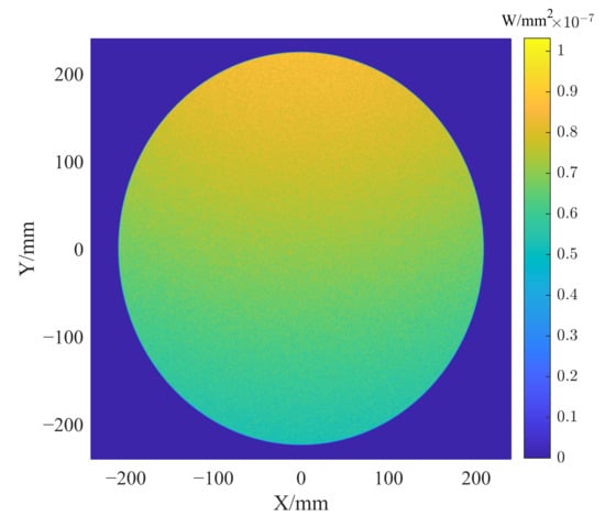
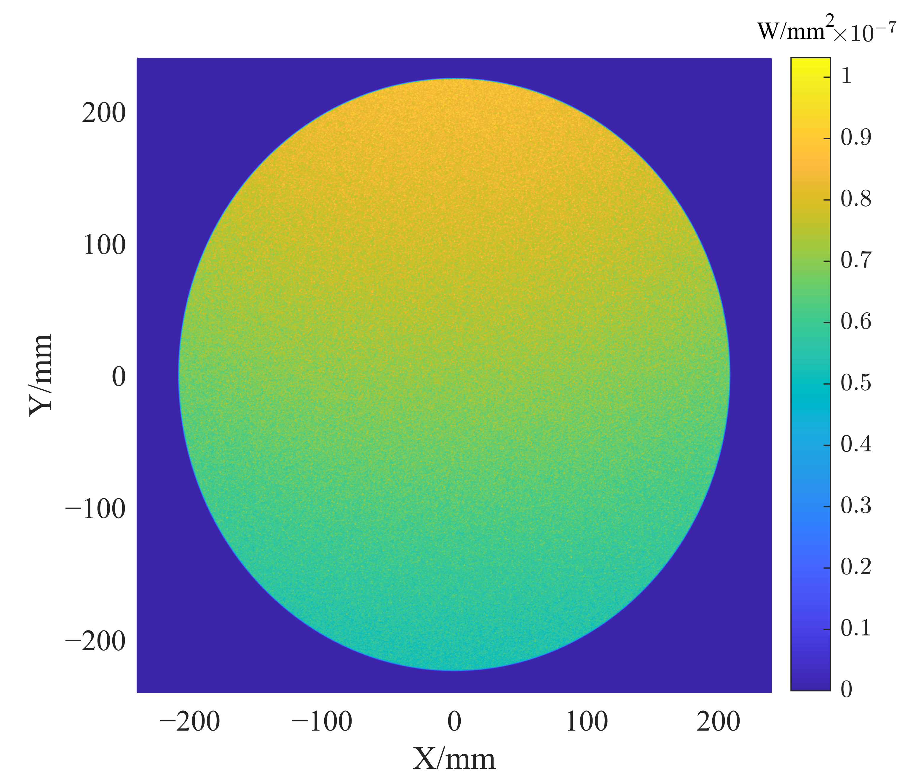
In practical applications, minimizing the effect of source fluctuations on the performance of the illumination system is desirable. The illumination system segments the light beam using the fly’s eyes and superimposes the beams onto the mask plane, forming a highly uniform illumination field. For the pupil, the proposed energy equalization algorithm groups the energy reflected by the FFMs. The reflected energy inherently includes the influence of source fluctuations, and therefore, constraining the energy consistency among different groups not only suppresses the impact of these fluctuations but also ensures energy uniformity across different regions of the pupil conjugate plane, thereby enhancing pupil performance. As shown in Figure 7, the far-field energy distribution of the source was intentionally biased during the simulation to verify the effectiveness of the energy equalization-based FFMs grouping algorithm.
Figure 7.
Far-field distribution of the light source.
3.1.4. Mirror Coating Reflectivity
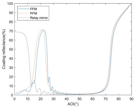
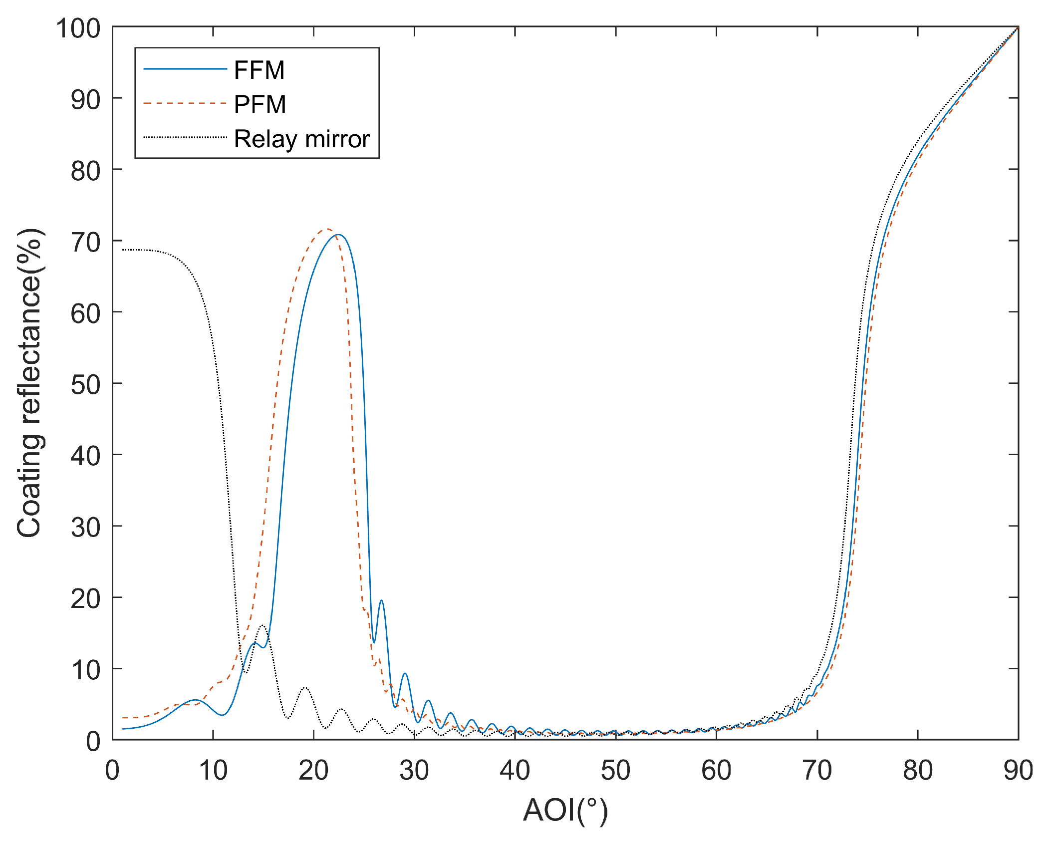
In EUVL illumination systems, Mo/Si multilayer coatings are applied to reflective mirrors to improve their reflectivity for EUV light, thereby achieving high energy transmission efficiency. The designed coatings were applied to the mirror surfaces when modeling the illumination system using the LightTools software. The reflectivity curves of the mirror coatings for the FFM, PFM and relay mirror are shown in Figure 8.
Figure 8.
Mirror coating reflectivity curve.
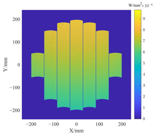
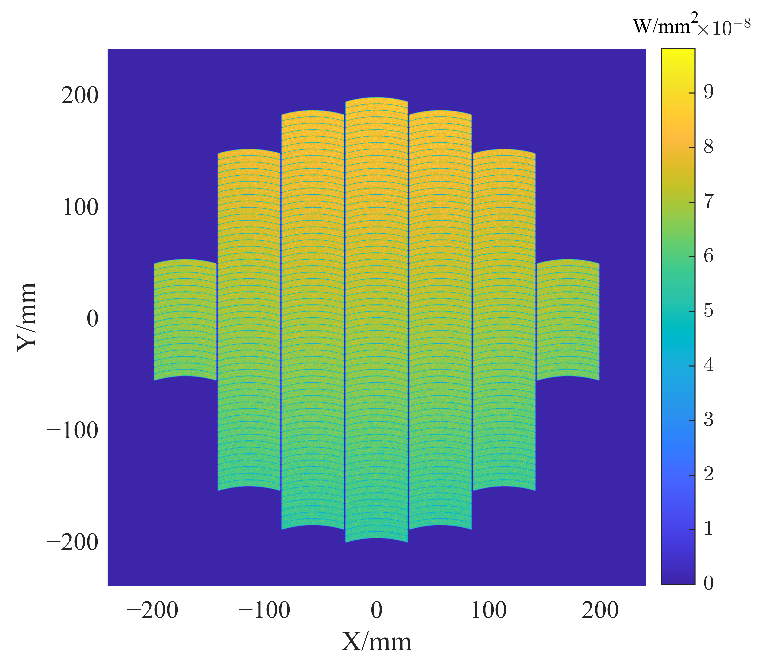
Obtaining the energy distribution of the light reflected by the FFMs before grouping the FFMs using the energy equalization algorithm is necessary because the coating reflectivity changes significantly with the angle of incidence. This step ensures high-energy consistency across different regions of the pupil conjugate plane. As shown in Figure 9, the energy reflected by each FFM element is calculated via image processing. At this stage, the obtained energy values incorporate the effect of coating reflectivity. Finally, the FFMs are grouped based on the energy equalization algorithm for achieving an even energy distribution on the PFMs. Consequently, the impact of this angle-dependent reflectivity was integrated into the constraints of the energy-equalization algorithm, thereby ensuring an excellent pupil performance.
Figure 9.
Reflected energy distribution of the FFMs.
3.2. Pupil Simulation Results
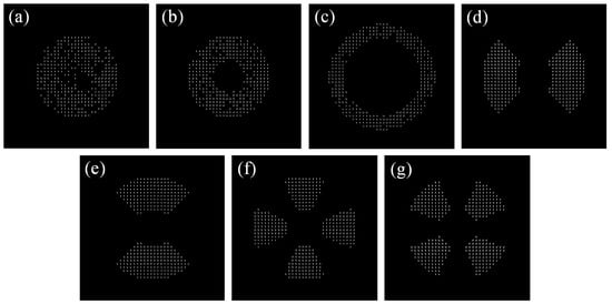
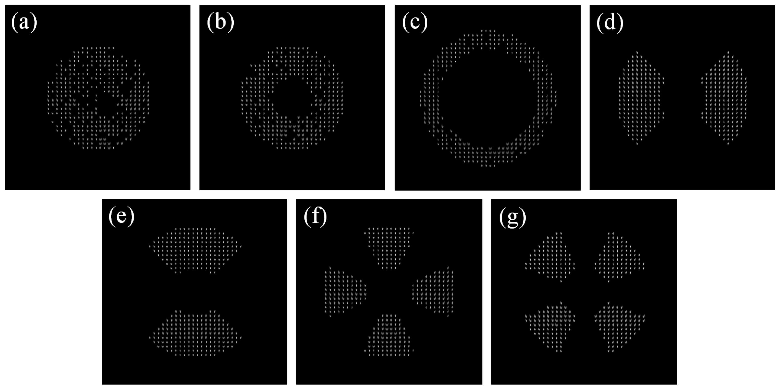
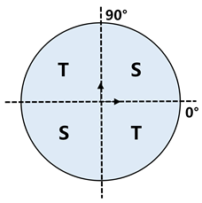
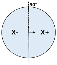
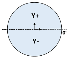
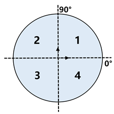
A total of 14 illumination modes across seven categories were achieved using the proposed algorithm. The PFM array was conjugated to the exit pupil, and therefore, we analyzed the pupil quality by examining the energy distribution on the PFM array instead of directly at the exit pupil. For clarity, one representative mode from each category was selected for analysis. Figure 10 shows the simulation results of these seven illumination modes. Pupil quality is evaluated based on pupil ellipticity and pole balance. The calculation methods for pupil ellipticity and pole balance, along with their applicable illumination modes, are listed in Table 3 [25]. The calculated results are presented in Table 4. For the aforementioned seven illumination modes, the maximum pupil ellipticity, X/Y-direction pole balance, and quadrant pole balance were 1.94%, 1.45%, and 1.82%, respectively. Moreover, higher-quality pupil performance can be achieved when combined with pupil optimization techniques [26].
Figure 10.
Simulated images of the pupil conjugate plane. (a) Conventional 1; (b) small annular 1; (c) large annular 1; (d) X dipole 1; (e) Y dipole 1; (f) 0° quadrupole 1; (g) 45° quadrupole 1.
Table 3.
Calculation methods of pupil ellipticity and pole balance and their applicable modes.
Table 4.
Results of the pupil characteristic parameters.
3.3. Illumination Field Simulation Results
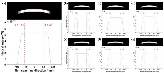
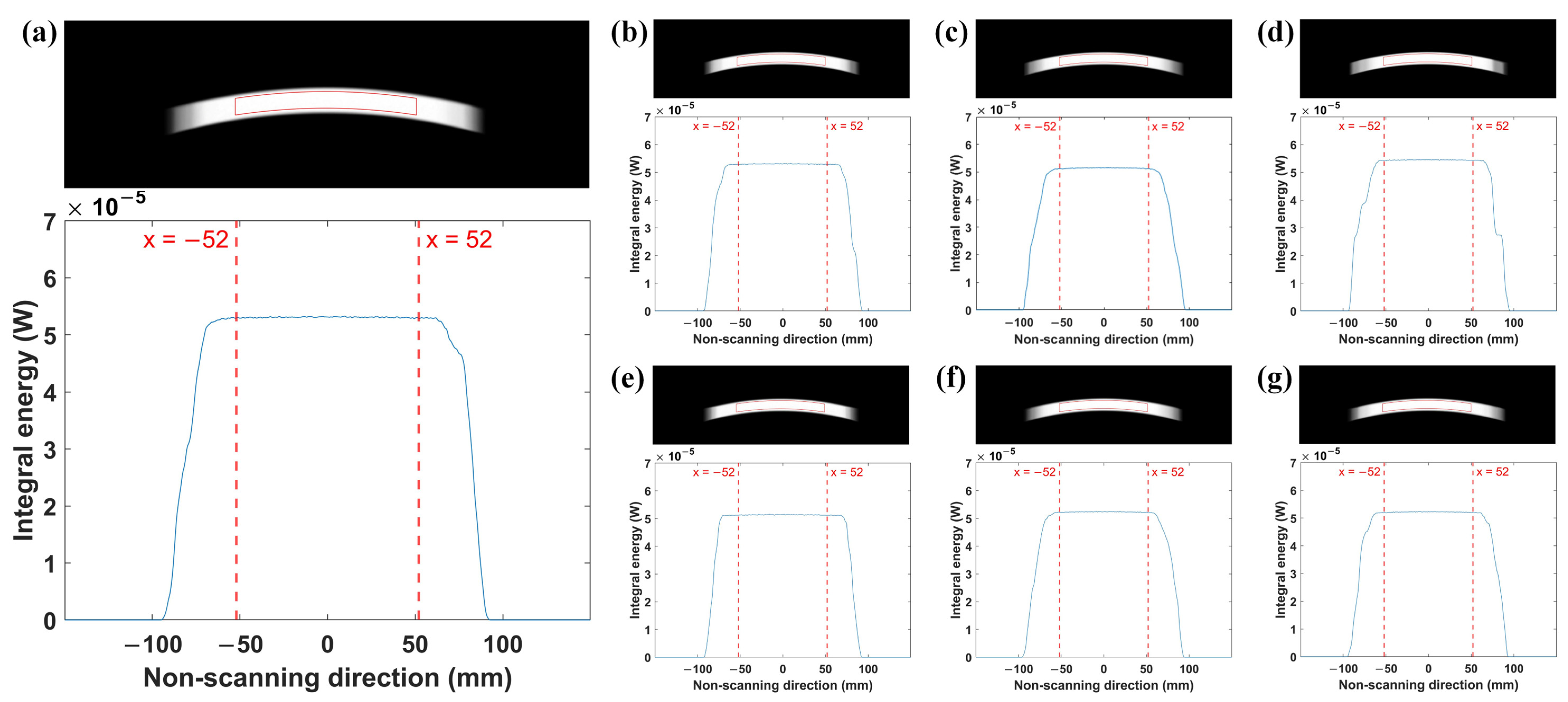
The quality of the illumination field on the mask plane is evaluated by the nonuniformity of the energy [27,28], which directly affects the linewidth of replicated mask patterns [29]. Figure 11 illustrates the simulated illumination field images and their non-scanning direction integral energy curves. The region outlined by the solid red line in the illumination field represents the effective area, which has dimensions of 104 mm × 10 mm. The calculation formula for the nonuniformity of the illumination field is [24,27]:
where and represent the maximum and minimum values of the energy integral in the scanning direction of the illumination field, respectively.
Figure 11.
Illumination fields and their energy integral curves in the non-scanning direction. (a) Conventional 1; (b) small annular 1; (c) large annular 1; (d) X dipole 1; (e) Y dipole 1; (f) 0° quadrupole 1; (g) 45° quadrupole 1. Zoom in for a better view.
The illumination field nonuniformity within the 104 mm × 10 mm area on the mask plane is calculated for the seven illumination modes, and the results are presented in Table 5. The calculation results indicate that the algorithm proposed in this paper achieves an illumination nonuniformity of 0.45–0.59% on the mask plane. This implies that all seven illumination modes meet the requirement of less than 1% nonuniformity even before correction [30,31]. Moreover, the illumination uniformity can be enhanced by incorporating uniformity correction techniques [32,33,34].
Table 5.
Nonuniformity of the illumination field.
3.4. Tolerance Analysis
In the practical applications of EUVL illumination systems, the assembly and alignment of the fly’s eyes are subject to extremely strict requirements for ensuring the performance of the illumination field and pupil. To verify the practical feasibility and robustness of the proposed algorithm, we conducted a tolerance analysis on the fly’s eyes of the illumination system, evaluating the impact of their positional errors on the illumination field and pupil performance. Taking the “Small annular 1” illumination mode as an example, we analyzed the effects of misalignments in each degree of freedom of the FFMs and PFMs on illumination field nonuniformity, pupil ellipticity, and pole balance. Finally, random positional errors with varying magnitudes and directions were assigned to the FFMs and PFMs to simulate realistic assembly and alignment errors, allowing us to analyze the resulting degradation in the system’s illumination field and pupil performance.
3.4.1. FFM Tolerance Analysis
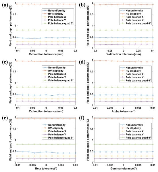
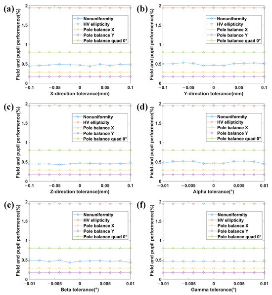
Considering practical manufacturing and assembly capabilities, translational tolerances ranging from −0.1 mm to 0.1 mm were set for the X/Y/Z degrees of freedom of the FFMs with a step size of 0.02 mm. The tilt angle tolerances for // were set from −0.01° to 0.01° with a step size of 0.002°. The tolerance values were incorporated into the optical model in the LightTools software, and simulations were conducted using 700 million rays. The resulting field nonuniformity, pupil ellipticity, and pole balance are shown in Figure 12.
Figure 12.
Effect of FFM tolerances in various degrees of freedom on system performance. (a) X-direction translation; (b) Y-direction translation; (c) Z-direction translation; (d) angle; (e) angle; (f) angle.
The simulation results confirm that, within the assigned tolerance range, misalignments in various degrees of freedom of the FFMs affect the field uniformity, pupil ellipticity, and pole balance to varying degrees. Compared to the ideal case without tolerances, the maximum degradation in field uniformity was 5.28%, whereas the maximum degradations in pupil ellipticity, X/Y direction pole balance, and 0° quadrant pole balance were 2.50%, 5.19%, and 0.94%, respectively.
Pose errors in FFMs cause the source image points to shift on the PFMs surface. The light intensity distribution on the PFMs is inevitably affected by changes in the pose of the FFMs because the illumination field on the mask plane is formed by the imaging of the FFMs through the PFMs, and the exit pupil of the illumination system is conjugated to the PFMs. Consequently, FFM pose misalignment affects both field and pupil performance. However, as revealed by the simulation results, the effect of FFM pose misalignment on the overall system performance remains relatively minor within a certain tolerance range.
3.4.2. PFM Tolerance Analysis
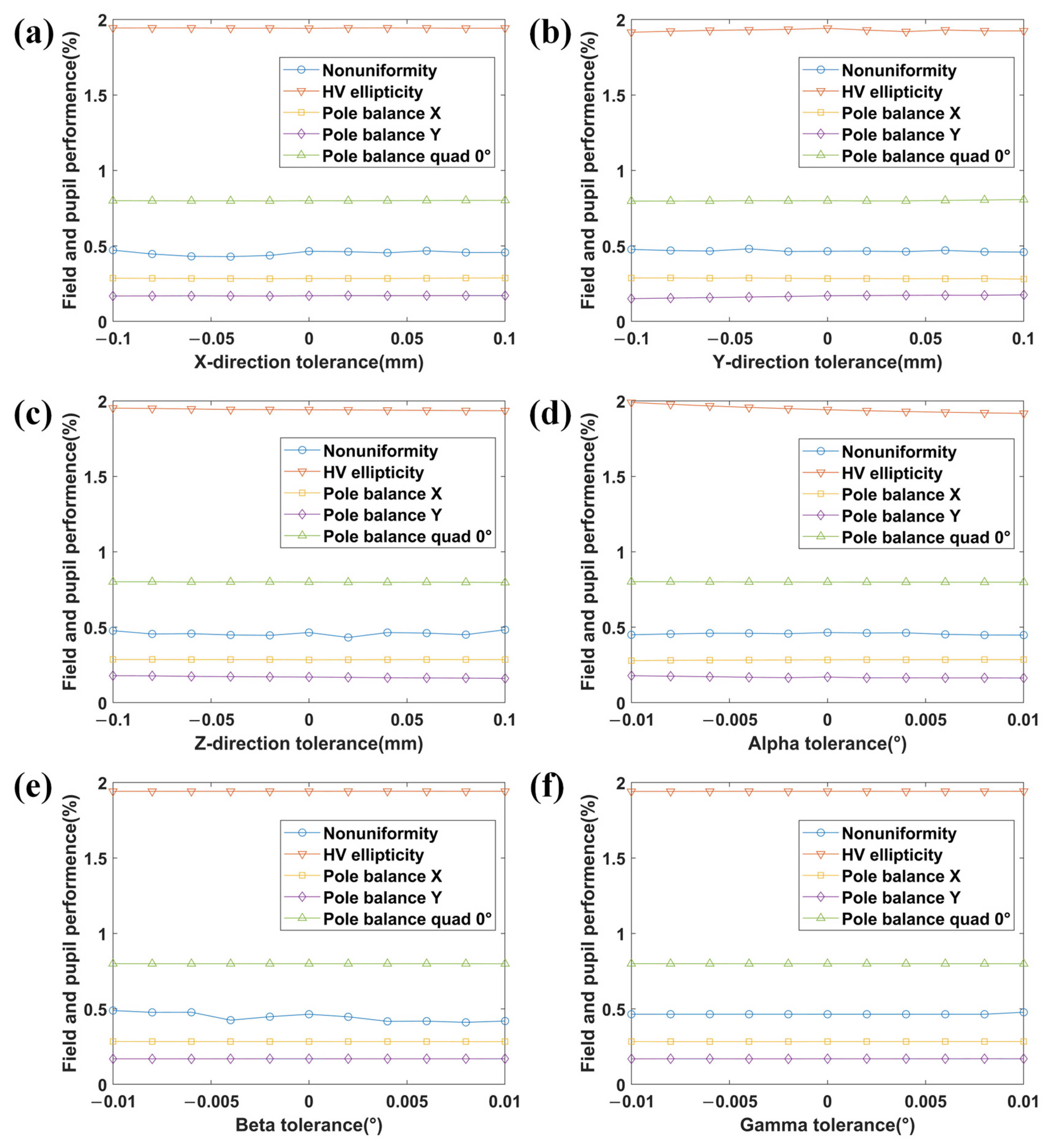
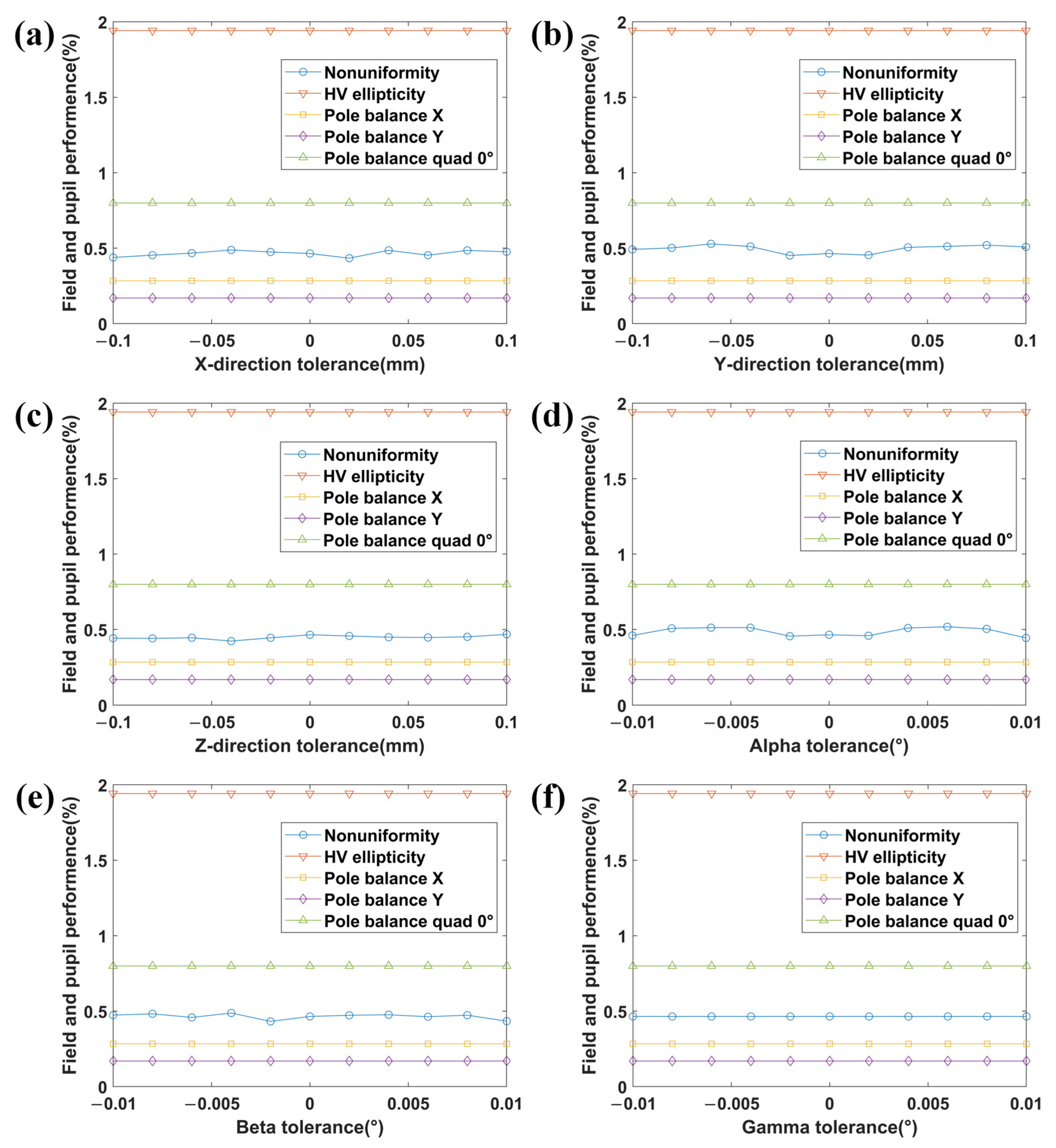
Similar to the FFM, translational tolerances ranging from −0.1 mm to 0.1 mm were set for the X/Y/Z degrees of freedom of the PFMs, with a step size of 0.02 mm. The tilt angle tolerances for // were set from −0.01° to 0.01°, with a step size of 0.002°. These tolerance values were incorporated into the optical model in LightTools software, and simulations were conducted using 700 million rays. The resulting field nonuniformity, pupil ellipticity, and pole balance are shown in Figure 13.
Figure 13.
Effect of PFM tolerances in various degrees of freedom on system performance. (a) X-direction translation; (b) Y-direction translation; (c) Z-direction translation; (d) angle; (e) angle; (f) angle.
According to the simulation results, the misalignments in the various degrees of freedom of the PFMs primarily affect the field uniformity within the assigned tolerance range. The maximum degradation in field uniformity reaches 11.48% compared to the ideal case without tolerances, whereas the pupil ellipticity and pole balance are barely affected. This can be attributed to the illumination field on the mask plane being formed by the superposition of images from the FFMs through the PFMs. Consequently, pose errors in the PFMs directly affect the uniformity of the illumination field. The system exit pupil is conjugated to the PFMs, and therefore, pupil performance is determined by the light intensity distribution on the PFMs surface. Pose errors in the PFMs have a relatively minor effect on pupil performance parameters because this intensity distribution is modulated by the pose of the FFMs.
3.4.3. Comprehensive Error Impact Analysis
In the practical operation of an illumination system, the misalignment magnitudes and directions of the degrees of freedom of fly’s eyes exhibit a random distribution owing to manufacturing and assembly variations. Random errors are assigned to all degrees of freedom of both the FFMs and PFMs to simulate the real working state of the illumination system and verify the effectiveness of the proposed algorithm. The extreme values of these errors are consistent with the tolerance analysis process mentioned above; however, the misalignment magnitudes and directions are randomized. Subsequently, ray tracing is performed to simulate the field and pupil performances of the system under this random misalignment condition.
Field nonuniformity measures the degree of unevenness of the integrated light intensity along the non-scanning direction of the illumination field, while pupil ellipticity and pole balance evaluate the energy differences across different regions of the pupil. Therefore, for both the illumination field and the pupil, smaller values of the performance parameters indicate better performance. The simulated field nonuniformity was 0.45%, representing a 3.061% improvement compared to the state without tolerances. The pupil performance parameters are listed in Table 6: pupil ellipticity decreased by 0.655%, X-direction pole balance slightly improved by 0.647%, Y-direction pole balance decreased by 7.020%, and 0° quadrant pole balance decreased by 0.797%. The above results indicate that the field and pupil performance of the illumination system may either improve or degrade. However, within a certain tolerance range, the degradation of the field and pupil performance obtained using the proposed algorithm is relatively minor. This confirms that the proposed algorithm exhibits a certain degree of practical feasibility and robustness.
Table 6.
Pupil performance under random tolerances.
4. Conclusions
EUVL illumination systems achieve different illumination modes and pupil shaping at the exit pupil by altering the facet-matching relationship between the FFMs and PFMs. The proposed algorithm breaks the constraints on the solution space inherent in traditional methods for solving facet-matching relationships. The proposed method solves for the facet-matching relationship by employing IE and pupil quality metrics as constraints and optimization objectives and utilizing integer programming combined with an energy equalization algorithm. This approach not only improves the energy efficiency of the illumination system but also ensures a highly uniform illumination field on the mask plane and a high-quality pupil.
An illumination system model was established using the LightTools software based on the facet-matching relationship obtained via the proposed algorithm. The simulation results demonstrate that the illumination field on the mask plane meets the nonuniformity requirement of less than 1% even prior to correction, with a maximum nonuniformity of 0.59% in the effective illumination field area. Various illumination modes were realized successfully at the exit pupil. For the seven modes analyzed in this study, the maximum pupil ellipticity, maximum X/Y pole balance and maximum quadrant pole balance were 1.94%, 1.45%, and 1.82%, respectively. These results confirm that the pupil-shaping technique based on integer programming and energy equalization effectively enhances pupil quality and offers new insights for the design of facet-matching algorithms in future EUVL illumination systems.
Author Contributions
Conceptualization, L.W. and Y.H.; methodology, Y.H., Q.Z., J.Y. and L.W.; software, Y.H.; validation, Y.H.; formal analysis, Y.H.; investigation, Y.H. and Q.Z.; resources, L.W.; data curation, Y.H. and Q.Z.; writing—original draft preparation, Y.H.; writing—review and editing, J.Y. and L.W.; visualization, Y.H.; supervision, J.Y. and L.W.; project administration, L.W.; funding acquisition, L.W. All authors have read and agreed to the published version of the manuscript.
Funding
This research was funded by the National Science Founding and Technology Major Project (No. 501100018537).
Data Availability Statement
The data supporting the conclusions of this article are not publicly available at this time but may be obtained from the authors upon reasonable request.
Conflicts of Interest
The authors declare no conflicts of interest.
Abbreviations
The following abbreviations are used in this manuscript:
| EUVL | Extreme ultraviolet lithography |
| CD | Critical dimension |
| EUV | Extreme ultraviolet |
| FFMs | Field facet mirrors |
| FFM | Field facet mirror |
| PFMs | Pupil facet mirrors |
| PFM | Pupil facet mirror |
| IF | Intermediate focus |
| IE | Illumination efficiency |
| SA | Simulated annealing |
| GA | Genetic algorithm |
| IP | Integer programming |
| AOI | Angle of incidence |
References
- Moore, G. Cramming more components onto integrated circuits. Electronics 1965, 38, 114–117. [Google Scholar]
- Michael, K. Moore’s Law to Roll on for Another Decade. Available online: https://www.cnet.com/news/moores-law-to-roll-on-for-another-decade (accessed on 10 February 2003).
- Wang, J. Optical Design of Extreme Ultra-Violet Lithography (EUVL) Objective System. Ph.D. Thesis, University of the Chinese Academy of Sciences, Changchun Institute of Optics, Fine Mechanics and Physics, Changchun, China, 2015. [Google Scholar]
- Li, Y. Lithography tool evolution and the trend of its development. Microfab. Technol. 2003, 2, 1–5+11. [Google Scholar]
- Guo, L.; Huang, H.; Wang, X. Off-axis illumination for optical lithography. Laser J. 2005, 26, 23–25. [Google Scholar]
- Jiang, J. Design of Extreme Ultraviolet Lithography Illumination System for Sub-11nm Node. Master’s Thesis, Beijing Institute of Technology, Beijing, China, 2017. [Google Scholar]
- Zimmermann, J.; Neumann, J.; Jürgens, D.; Gräupner, D. Status and outlook of EUV optics at ZEISS. In Proceedings of the International Conference on Extreme Ultraviolet Lithography, Monterey, CA, USA, 2–5 October 2023; Volume 12750, pp. 190–195. [Google Scholar]
- Liu, F. Design of Coaxial Extreme Ultraviolet Lithographic Projection Objective. Ph.D. Thesis, Beijing Institute of Technology, Beijing, China, 2014. [Google Scholar]
- Hu, Z.; Yang, B.; Zhu, J.; Xiao, Y.; Zeng, A.; Huang, L.; Zhao, Y.; Huang, H. Pupil shaping techniques in high resolution projection exposure tools. Laser Optoelectron. Prog. 2011, 48, 42–49. [Google Scholar] [CrossRef] [Scilit]
- Li, Y.; Mei, Q.; Liu, F. EUV Illumination System with Compound Eye Homogenizer and Off-Axis Illumination, and Method for Implementing Off-Axis Illumination. CN 103092000A, 8 May 2022. [Google Scholar]
- Wang, X.; Li, Z.; Yuan, C. Pupil-shaping technique in extreme ultraviolet lithography illumination system. Chin. J. Lasers 2024, 51, 377–389. [Google Scholar] [CrossRef]
- Hans-Juergen, M.; Wolfgang, S.; Joerg, S.; Johannes, W.; Karl-Heinz, S.; Udo, D.; Martin, A.; Wilhelm, U. Illumination System Particularly for Microlithography. U.S. Patent Application 20080130076, 9 January 2026. [Google Scholar]
- Rudy, P.; Sjoerd, L.; Erwin, A. ASML’s NXE platform performance and volume introduction. In Proceedings of the Extreme Ultraviolet (EUV) Lithography IV, San Jose, CA, USA, 25–28 February 2013; Volume 8679, pp. 381–395. [Google Scholar]
- Van De Kerkhof, M.; Jasper, H.; Levasier, L.; Peeters, R.; Van Es, R.; Bosker, J.-W.; Zdravkov, A.; Lenderink, E.; Evangelista, F.; Broman, P.; et al. Enabling sub-10nm node lithography: Presenting the NXE:3400B EUV scanner. In Proceedings of the Extreme Ultraviolet (EUV) Lithography VIII, San Jose, CA, USA, 27 February–2 March 2017; Volume 10143, pp. 34–47. [Google Scholar] [CrossRef] [Scilit]
- Lowisch, M.; Kuerz, P.; Conradi, O.; Wittich, G.; Seitz, W.; Kaiser, W. Optics for ASML’s NXE:3300B platform. In Proceedings of the Extreme Ultraviolet (EUV) Lithography IV, San Jose, CA, USA, 24–28 February 2013; Volume 8679, pp. 404–412. [Google Scholar] [CrossRef] [Scilit]
- Murakami, K.; Oshino, T.; Kondo, H.; Chiba, H.; Komatsuda, H.; Nomura, K.; Iwata, H. Development status of projection optics and illumination optics for EUV1. In Proceedings of the Emerging Lithographic Technologies XII, San Jose, CA, USA, 24–29 February 2008; Volume 6921, p. 222. [Google Scholar]
- Hoduk, C.; Seongbo, S.; Hyungjong, B.; Chan, H. Extreme Ultraviolet Lithography Device and Method of Operating Extreme Ultraviolet Lithography Device. U.S. Patent Application 20230393484, 7 December 2023. [Google Scholar]
- Li, J. Researches on Capillary Discharge Xe Plasma EUV Source with High Repetition Frequency Mode. Master’s Thesis, Harbin Institute of Technology, Harbin, China, 2023. [Google Scholar]
- Xu, Q. Study on EUV Source of Z-Pinch Xe Plasma Pumped by Capillary Discharge. Ph.D. Thesis, Harbin Institute of Technology, Harbin, China, 2014. [Google Scholar]
- Zeng, J.; Gao, C.; Yuan, J. Plasma light sources for extreme UV lithography and their optical properties. Wuli 2007, 7, 537–542. [Google Scholar]
- Graham, R. Bounds for certain multiprocessing anomalies. Bell Syst. Tech. J. 1966, 45, 1563–1581. [Google Scholar] [CrossRef] [Scilit]
- Coffman, E.G.; Garey, M.R.; Johnson, D.S. An application of bin-packing to multiprocessor scheduling. SIAM J. Comput. 1978, 7, 1–17. [Google Scholar] [CrossRef] [Scilit]
- Bodenstaff, L.; Wieringa, R.; Wombacher, A.; Reichert, M. Towards management of complex service compositions—Position paper. In Proceedings of the IEEE 2009 World Conference on Services—II, Bangalore, Karnataka, India, 21–25 September 2009. [Google Scholar] [CrossRef] [Scilit]
- Mei, Q. Optical Design of Free-Form Illumination System for Extreme Ultra-Violet Lithography Tool. Ph.D. Thesis, Beijing Institute of Technology, Beijing, China, 2016. [Google Scholar]
- Zhu, S.; Yang, B.; Ma, X.; Zhang, F.; Cheng, W.; Niu, Z.; Huang, H. Research on High Energy Efficiency Pupil Correction Based on Multi-ring Partition in Photolithography Machine. Chin. J. Lasers 2021, 48, 1704001-2. [Google Scholar]
- Last, T.; de Winter, L.; van Adrichem, P.; Finders, J. Illumination pupil optimization in 0.33NA EUVL by intensity balancing for semi-iso dark field two-bar M1 building blocks. In Proceedings of the 32nd European Mask and Lithography Conference, Dresden, Germany, 21–22 June 2016; Volume 10032, pp. 63–69. [Google Scholar]
- Jiang, J.; Mei, Q.; Li, Y.; Liu, Y. Illumination system with freeform fly’s eye to generate pixelated pupil prescribed by source-mask optimization in extreme ultraviolet lithography. Opt. Eng. 2017, 56, 065101. [Google Scholar] [CrossRef] [Scilit][Green Version]
- Stig, B.; Martin, E. Beleuchtungsoptik für die EUV Projektionslithographie. DE102020208451A1, 10 June 2021. [Google Scholar]
- Jin, C. Investigation on Extreme Ultraviolet Lithography. Ph.D. Thesis, University of the Chinese Academy of Sciences, Changchun Institute of Optics, Fine Mechanics and Physics, Changchun, China, 2003. [Google Scholar]
- Xu, M. Optical Design for the Hyper Numerical Aperture Lithographic Lens. Ph.D. Thesis, University of the Chinese Academy of Sciences, Changchun Institute of Optics, Fine Mechanics and Physics, Changchun, China, 2015. [Google Scholar]
- Li, Y.; Nan, Y.; Chen, Y.; Yan, X.; Zhang, X.; Liu, L. Research and progress on optical design of exposure systems in extreme ultraviolet lithography. Acta Opt. Sin. 2023, 43, 328–343. [Google Scholar]
- Damian, F.; Berndt, W.; Christian, S.; Martin, E.; Ralf, S.; Jens, O.; Ralf, S.; Markus, H.; Udo, D.; Severin, W.; et al. Illumination Optics for EUV Microlithography and Related System and Apparatus. U.S. Patent Application 8587767, 19 November 2013. [Google Scholar]
- Ma, X.; Zhang, F.; Huang, H. Correction technology for illumination field intensity profile in photolithography machine. Chin. J. Lasers 2021, 48, 69–80. [Google Scholar]
- Cheng, W.; Zhang, F.; Lin, D.; Zeng, A.; Yang, B.; Huang, H. High precision correction method of illumination field uniformity for photolithography illumination system. Acta Opt. Sin. 2018, 38, 262–271. [Google Scholar] [CrossRef] [Scilit]

Disclaimer/Publisher’s Note: The statements, opinions and data contained in all publications are solely those of the individual author(s) and contributor(s) and not of MDPI and/or the editor(s). MDPI and/or the editor(s) disclaim responsibility for any injury to people or property resulting from any ideas, methods, instructions or products referred to in the content. |
© 2026 by the authors. Licensee MDPI, Basel, Switzerland. This article is an open access article distributed under the terms and conditions of the Creative Commons Attribution (CC BY) license.