Article

Broadband Optical Edge Detection Based on Two-Dimensional Liquid Crystal Polarization Grating


Key Laboratory of Light Field Manipulation and Information Acquisition, Ministry of Industry and Information Technology, School of Physics Science and Technology, Northwestern Polytechnical University, Xi’an 710129, China
*
Author to whom correspondence should be addressed.
Photonics 2026, 13(7), 639; https://doi.org/10.3390/photonics13070639
Submission received: 4 June 2026 / Revised: 23 June 2026 / Accepted: 30 June 2026 / Published: 1 July 2026
(This article belongs to the Special Issue Latest Advances in Optical Diffraction, Imaging and Display)

Abstract

A two-dimensional liquid crystal polarization grating (2D-LCPG) is realized by using a single-exposure photoalignment system. When using a horizontal polarized light as the reference incident light, four circular polarized light beams are captured with a 4f system to realize image extraction and detection. Compared with a 1D-LCPG, the experimental results demonstrate better integrity and accuracy in extracting edge information with the proposed 2D-LCPG. Broadband edge detection capability was tested under visible wavelength range. Results show good edge detection even without an electric field. The resolutions are up to 15.63 µm for incident light of 633 nm, 532 nm by applying a 0.3 V/µm electric field, and 450 nm by applying a 0.5 V/µm electric field. With these advantages, optical edge detection based on the proposed 2D-LCPG could have potential applications in image processing, remote sensing, and other related areas.

1. Introduction

Edge detection serves as an important technique in image information processing [1,2,3]. It enables precise localization of object boundaries and extraction of crucial image features [4], achieving effective image preprocessing. Thus, edge detection technologies attract increasing attention in computer vision, biomedical imaging, and smart vision systems [5].When large-scale parallel processing of image data is required, the detection efficiency of digital edge detection [6,7] can be spotty. Compressing redundant data improves the computational efficiency of image recognition algorithms, and this has been widely deployed in various high-end application scenarios, including satellite remote sensing, biomedical imaging, and smart vision systems.
Conventional edge detection methods identify edge contours by calculating the luminance gradient derivative of digital image matrices, whereby pixels with drastic brightness variations are extracted as edge features. Nevertheless, the processing efficiency of these methods is inherently limited by image quality and computational hardware capability. For high-resolution images carrying massive data volumes, traditional digital methods suffer from severely degraded efficiency, especially in scenarios requiring large-scale parallel image processing.
To address the issues of data redundancy and low computational efficiency, optical edge detection has emerged as a promising alternative. This technique can capture clear edge information directly during image acquisition, accelerating the overall image information processing speed.
In the past few years, several optical edge detection methods based on metasurfaces, LCs, photonic crystals, and other complex array structures have been proposed. By designing corresponding sub-wavelength optical devices, the preliminary extraction of edge information has been realized to facilitate the subsequent image processing [8,9,10,11,12,13,14,15,16,17]. In addition, in recent years, several previous efforts have exploited striking approaches to realizing efficient edge detection. Various optical differentiators have been used to perform analog computation and operations have been designed to extract edge information or enhance the image [15,18,19,20,21,22,23,24,25,26,27,28,29] with low to no power consumption. Furthermore, LC planar devices based on the Pancharatnam–Berry (PB) phase such as PB lenses (PBLs) and polarization gratings (PGs) have also been investigated to function as image processors [30,31,32,33,34,35] owing to their high diffractive efficiency and compact size.
However, the production of a metasurface structure is complicated and costly and the structures also lack flexibility. Optical edge detection based on 1D-LCPGs can only extract the edge of one dimension, while two-dimensional optical edge detection based on LC PBLs will shrink the original image size to a certain extent and cannot be applied to broadband scenarios. Thus, 2D-LCPGs can be an alternative for high-quality broadband edge detection. To date, there have been several digital photoalignment methods available to fabricate complicated LCPG patterns, such as exposure photoalignment based on SLMs [36,37] or DMDs [38,39] and laser direct-writing [40].We designed a single-step exposure setup based on SLMs to realize the alignment of LCs [41].
In this paper, we propose an optical edge detection device based on a 2D-LCPG. The 2D-LCPG cell was fabricated by a single-step exposure system based on a SLM. Light can be steered to four spots and overlapped in the middle part. After filtering the middle region information, the edge information can be displayed. The results show better edge detection ability in all visible wavelength ranges. In addition, the device is easy to prepare, with low cost, making it more suitable for many applications such as satellite remote sensing, biomedical imaging, and smart vision systems.

2. Principles

To realize the two-dimensional optical edge detection of given objects, in this paper, the diffraction order of the designed 2D-LCPG is symmetrically divided into (1, 0), (−1, 0), (0, 1), and (0, −1). The optical path length of the LCPG satisfies the half wavelength condition of incident light (633 nm). The LC molecules are periodically oriented along the x-axis and y-axis, and the periodic structure satisfies Tx = Ty = Λ. Hence, when a beam of horizontal linearly polarized light is incident on the 2D-LCPG, the transmission function of the grating is given by:
T = R ϕ exp i Γ 2 0 0 exp i Γ 2 R ϕ
where Γ = 2πΔnd/λ denotes the dynamic phase delay of output light gained from the grating and Δn denotes the birefringence index of the LC, d denotes the thickness of the LC cell. R(φ) and R(−φ) are rotation matrices, where φ denotes the azimuth of the LC molecule.
According to Fraunhofer diffraction, the far-field diffraction from the grating is expressed as:
E m = 1 Λ x 1 Λ y 0 Λ x 0 Λ y TE i n exp ( i 2 π m x Λ x ) exp ( i 2 π n x Λ y ) d x d y
When a beam of linearly polarized incident passes through a 2D-LCPG, according to Fraunhofer’s diffraction formula, there are two sets of orthogonal polarization states consisting of four beams of circular polarized light. The diffraction angle of the transmitted light to the propagation direction of the original incident light can be expressed as sinθ = λ/Λ along both the x-axis and y-axis. When the period of the LCPG is much larger than the wavelength of the incident light, the two beams of transmitted light after the LCPG will obtain a tiny shift:
Δ x = f × sin θ x . Δ y = f × sin θ y
Once the period of the 2D-LCPG is large enough, most of the four transmitted light beams will be concentrated in the center, except for the edge part. The 2D-LCPG leads to the transmitted light shifting a distance of Δx = Δy = Δ along the x-axis and y-axis, respectively.
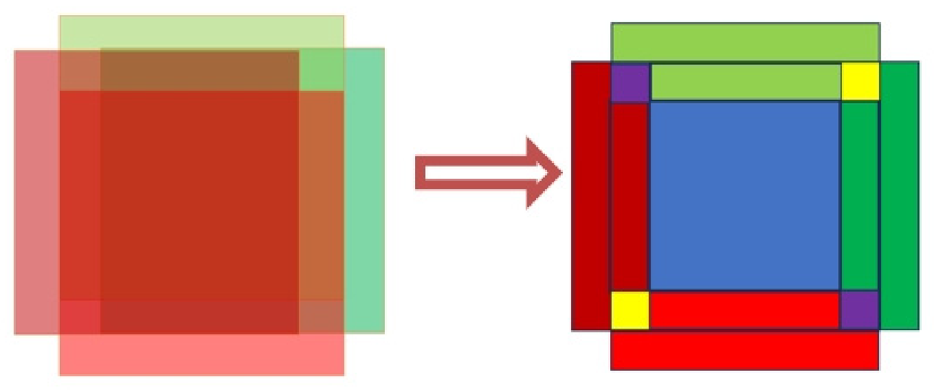
Figure 1 is the illustration of edge detection based on the 2D-LCPG, where the blue area represents the initial linearly polarized light, the red area represents the left-handed circular polarized light, the green area represents the right-handed circular polarized light, and the shades of color represents the different original phases. The yellow area represents the superposition of the identical circularly polarized light, whereas purple represents the superposition of the left and right circular polarized light with different original phases. When the four beams of light are overlapped, they interfere forming a beam of linearly polarized light the same as the input light. Thus, in the central area, this it can be filtered out by a polarizer. In the yellow area, peripheral left and right circular polarized light carrying edge information will be enhanced. But in purple section, non-horizontal light will show attenuated, but not zero, light intensity after polarization. Hence, we can extract all edge information after light is filtered by a polarizer.

3. Fabrication of the 2D-LCPG and Experimental Setup

With the help of the photoalignment method, a complex aligning structure became possible. A polarization photosensitive alignment sulphonic azo-dye (SD1) was chosen as the aligning material due to its flexible anchoring energy, lack of mechanical damage, and minimized unwanted electronic charges. Under exposure from a polarized light source with the UV-to-blue spectrum, the SD1 molecule tends to orient perpendicularly to the polarization of the incident light [42]. Two optically flat indium tin oxide-coated glass plates were used to prepare a sandwich-type sample holder. SD1 was coated by a spin coater at 3000 r/mins for 30 s. Spacers were used to form the sandwich-like structure. The designed pattern was exposed on the cell using the exposure system. A nematic liquid crystal E7 (Merck) was then filled into the cell after heating to its isotropic temperature. The ordinary and extraordinary refractive indices of E7 are approximately no = 1.521 and ne = 1.746 at 633 nm, corresponding to a birefringence of Δn ≈ 0.225. These optical parameters were used to determine the cell thickness according to the half-wave condition. The cell thickness was designed to be 4.2 μm according to the half-wave condition, Δnd = λ/2, for an operating wavelength of 633 nm. The single-step exposure system consists of a light source, a Glan–Taylor prism (GTP), a beam expander (BE), a lens, a planar mirror, a half-wave plate (HWP), a right-angle prism (RAP), a spatial light modulator (SLM), and a quarter-wave plate (QWP). The light source is a fiber laser with a working wavelength of 450 nm, providing both a wavelength suitable for the alignment layer response and stable energy for the system. Different grayscale images are loaded onto the spatial light modulator to achieve different orientations of the LC molecules [41].The exposure system has the resolution of 7 μm and 2 μm according to size of light spot; in our experiment, resolution of 7 μm was used.
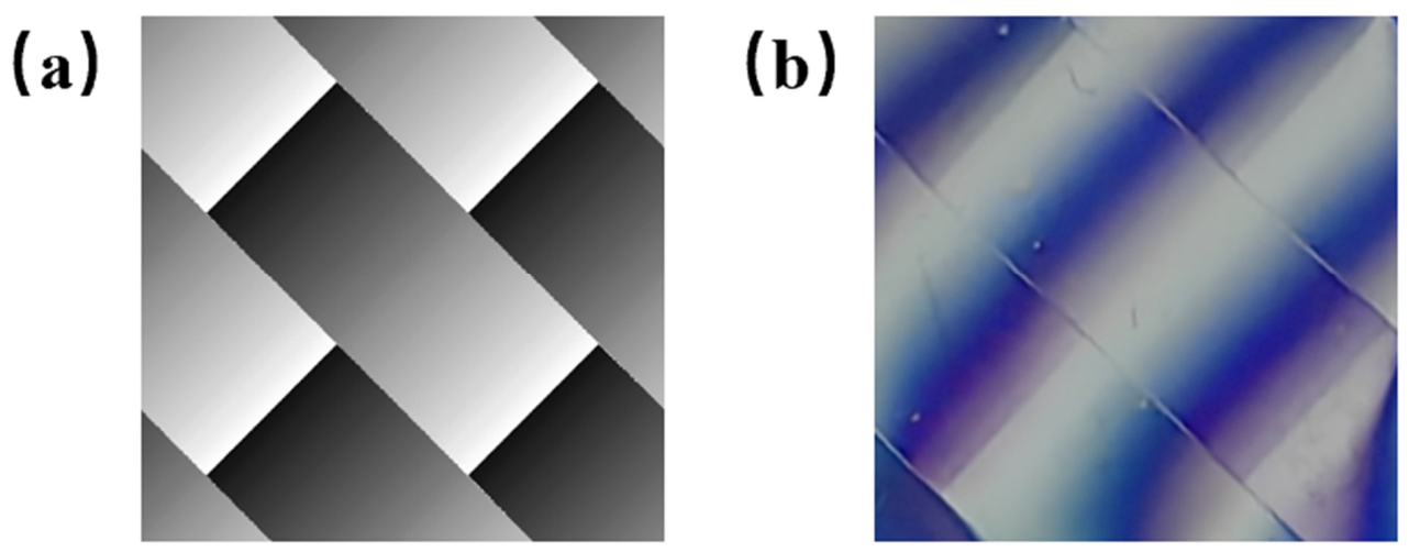
The fabricated LC cell has an overall size of 1.3 cm × 1.7 cm, while the effective patterned region of the 2D-LCPG is about 7 mm × 7 mm with grating period of 4200 μm × 4200 μm. The exposure area should at least cover one grating period to preserve the integrity of the image edge information. Figure 2a demonstrates the grayscale image of the designed 2D-LCPG loaded on the SLM. Figure 2b shows a microscopic photograph captured under crossed polarizers fabricated with the grayscale image. Within the effective area, the thickness of the liquid crystal cell was tested in different points to ensure it was uniform. It can be distinctly observed that the prepared 2D-LCPG was consistent with the predesigned structure.
Performance testing of the LCPG was conducted. Using a power meter, the optical intensities of the diffraction orders (1, 0), (−1, 0), (0, 1), and (0, −1) were measured to be 43.1 μw, 44.2 μw, 43.7 μw, and 44.1 μw, respectively. The measured intensity distribution was in good agreement with the relative intensity profile. The first order diffraction efficiency was over 92% with hardly observable zero order. By measuring the distances from each diffraction spot to the optical axis center and the distance between the CCD and the device, the deflection angle was determined to be approximately 0.012°, which is consistent with the theoretical simulation results.
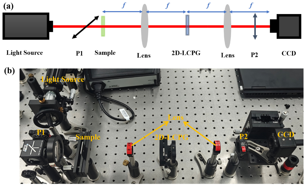
Edge detection is essentially a filtering differential operation and can be implemented in a 4f system with two orthogonal polarizers. The 4f system is a representative of coherent filtering systems, and its setup configuration is shown in Figure 3. The system is composed of two Fourier lenses with focal length f, and the rear focal plane of the first lens L1 coincides with the front focal plane of the second lens L2. The designed 2D-LCPG is located on the Fourier plane of the 4f system, which serves as a modulator. As a result, a reversed and equal-sized image of the object is formed in the image plane of the 4f system. Two crossed polarizers are located in the rear of the collimated light and the front of image plane of 4f system, respectively. The final image is recorded by a CCD. The experiment employed a 633 nm horizontally polarized laser source as the output. The focal lengths of the two lenses were both 10 cm, and the CCD was mounted on a translation stage with a minimum positioning resolution of 2 μm.

4. Results and Discussion

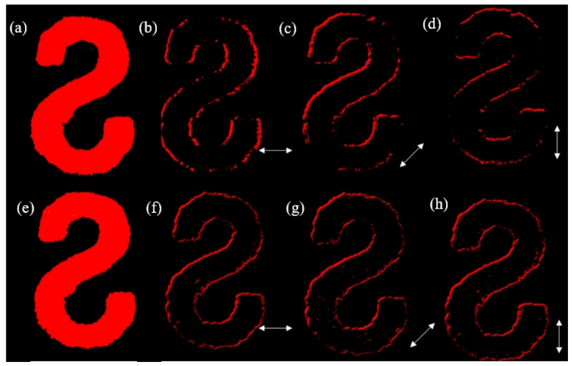
To evaluate the quality and feasibility of edge detection, we tested and compared the integrity of edge information extracted by placing a 1D-LCPG and the 2D-LCPG on the Fourier transform plane of the 4f system, and observing whether the information was lost or blurred in all directions. At the outset, as the test object, we used a stencil with an “S” hollowed-out, whose outermost edge has a diameter of 0.5 cm. Results are visually shown in Figure 4.
Figure 4a–d show the results of edge detection based on the 1D-LCPG, and Figure 4e–h show the results of edge detection based on the 2D-LCPG. Figure 4a,e indicate the light intensity distribution images containing edge information captured by the CCD without a polarizer. These images verify that there was clear and intact edge information, and present a clear pattern “S” without optical aberration. Figure 4b–d indicate the light intensity distribution with edge information obtained by placing the 1D-LCPG at different rotation angles on the spectrum plane after passing through the polarizer. The white arrows demonstrate the periodic directions of the LC molecules, as examples, which are 0°, 45°, and 90°, respectively. Observations indicate the loss of edge information on the part of the “S” that is perpendicular to the periodic change direction of the LC molecules. Furthermore, looking at the direction of these edge information losses, we can see that the degree of edge detection information loss was different based on the 1D-LCPG being placed at different angles in x−y plane. The loss of edge information is particularly noticeable for the edges perpendicular to the periodic direction of LC molecules, while for edges that are approximately parallel to the direction of periodic changes of LC molecules, information loss gradually decreases. In contrast, this problem does not appear when we use the designed 2D-LCPG for edge information extraction. Specifically, as shown in Figure 4e–h, no matter how the angle of the LC device is rotated in the x−y plane, the edge information always remains clear-cut and intact without blurs or conspicuous loss.
The reason for the difference between 2D-LCPGs and 1D-LCPGs in optical edge detection is the arrangement of LC molecules. The left and right circular polarized light produced by a 1D-LCPG is only distributed along the x-axis, while the four different transmitted light beams generated by a 2D-LCPG output along the x-axis and y-axis, avoiding the loss of edge information in a certain direction. To quantitatively evaluate the performance of the 2D-LCPG, we measured the minimum and maximum edge widths as well as the signal-to-noise ratio (SNR) of the edge intensity. The corresponding values are listed in Table 1. It can be seen that the 1D-LCPG and 2D-LCPG exhibited comparable performance in terms of edge information extraction. A high resolution of 6 µm to ~40 µm could be obtained. Moreover, the 2D-LCPG was capable of retrieving more comprehensive edge information.
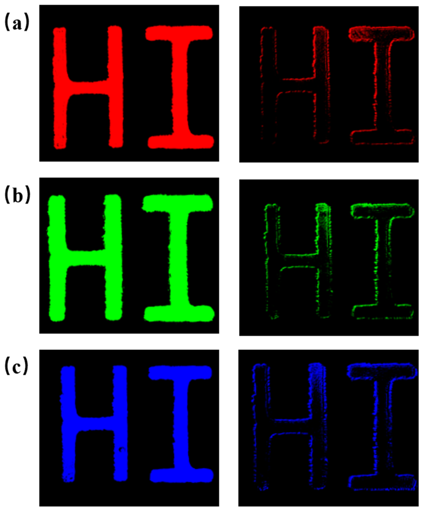
After verifying the edge detection capability of the 2D-LCPG in maintaining information integrity, we further studied its application in a wide wavelength range. In further experiments, we used three representative wavelengths of 450 nm, 532 nm, and 633 nm as input light. We applied a corresponding electric field, and experimental results can be seen in Figure 5.
The pictures in left column in Figure 5 show images of light transmitting by the 2D-LCPG without a polarizer; the character contour is fuzzy left-handed circular polarization and right-handed circular polarization. The pictures in right column in Figure 5 show the edge image when light is transmitted through the 2D-LCPG and then filtered out by the polarizer. It can be clearly seen that the edge contour of the word “HI” is completely extracted, without blurs or any loss of detail. Table 2 presents the corresponding minimum and maximum edge widths as well as the SNR. The results also show the high resolution and low SNR.
When no electric field are applied, different wavelengths of incident light will only affect the diffraction efficiency of the central 0-order diffracted light. Although the diffraction efficiency of the 0-order at different wavelengths is different, the 0-order light polarization is still consistent with the input linearly polarized light and thus can be filtered out by the orthogonal polarizer. By applying an electric field, the diffraction efficiency can be maintained, as well as the performance of edge detection.
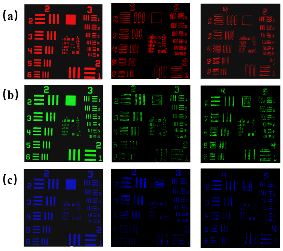
Considering the requirements of image processing, resolutions of edge detection at different wavelengths that were tested are shown in Figure 6. Subgraphs, from left to right, show images captured without a polarizer, with a polarizer, and enlarged images with a polarizer in front of the CCD. Experimental results prove that the minimal resolution reached the element 1 in Group 5 (32 lp/mm, where lp represents line pair) for incident light at 633 nm, corresponding to the resolution of 15.63 µm. Even the half-wave optical path length of the 2D-LCPG we prepared is suited for the incident light at 633 nm; the minimal resolution of incident light at 532 nm and 450 nm are still approximately 15.63 µm if electric fields of 0.3 V/µm and 0.5 V/µm were used, respectively.
The above results show that by using the proposed 2D-LCPG, the overall performance of edge detection is enhanced with better image quality and wider wavelength range. In principle, the proposed 2D-LCPG can also operate at wavelengths beyond the visible range. By redesigning the LC cell thickness for the target wavelength (for example near infrared) and applying an appropriate driving voltage, the device can work less than the designed wavelength within a certain range.

5. Conclusions

In this paper, we have proposed a method for image edge detection with a 2D-LCPG. The 2D-LCPG was fabricated by using a single-step-exposure photoalignment system. A 4f system was built to realize extraction and detection of 2D optical edge information. Experimental results demonstrate better integrity and accuracy in extracting edge information with the proposed 2D-LCPG compared with a 1D-LCPG, and verify its potential in broadband edge detection. The resolutions can be up to 15.63 µm for incident light of 633 nm, 532 nm by applying 0.3 V/µm electric field, and 450 nm by applying 0.5 V/µm electric field. Optical edge detection based a 2D-LCPG overcomes high consumption and low processing speed, while realizing better real-time preliminary extraction of object edge information within a broadband range, providing convenience for the subsequent image processing and providing a promising application prospect.

Author Contributions

Conceptualization, Y.M. and Y.S.; methodology, H.L. and Z.Y.; software, X.L.; validation, Y.M., H.L., Z.Y. and X.L.; writing—original draft preparation, Y.S.; writing—review and editing, Y.M. and H.L.; supervision, Y.M. All authors have read and agreed to the published version of the manuscript.

Funding

Natural National Science Foundation of China (NSFC) (62275220).

Institutional Review Board Statement

Not applicable.

Informed Consent Statement

Not applicable.

Data Availability Statement

Data are available from the authors on request.

Conflicts of Interest

The authors declare no conflict of interest.

References

  1. Franke, U.; Gavrila, D.M.; Görzig, S.; Lindner, F.; Paetzold, F.; Wöhler, C. Autonomous Driving Goes Downtown. IEEE Intell. Syst. Their Appl. 1998, 13, 40–48. [Google Scholar] [CrossRef]
  2. Mira, J.D.; Mayer, J. Image feature extraction for application of biometric identification of iris—A morphological approach. In Proceedings of the 16th Brazilian Symposium on Computer Graphics and Image Processing (SIBGRAPI 2003), Sao Carlos, Brazil, 12–15 October 2003; pp. 391–398. [Google Scholar]
  3. Cognard, T.E.; Goncharov, A.; Devaney, N.; Dainty, C.; Corcoran, P. A Review of Resolution Losses for AR/VR Foveated Imaging Applications. In Proceedings of the 2018 IEEE Games, Entertainment, Media Conference (GEM), Galway, Ireland, 15–17 August 2018; pp. 1–9. [Google Scholar]
  4. Marr, D.C.; Hildreth, E. Theory of edge detection. Proc. R. Soc. Lond. 1979, 207, 187–217. [Google Scholar]
  5. Hsu, H.-S.; Tsai, W.-H. Moment-preserving edge detection and its application to image data compression. Opt. Eng. 1993, 32, 1596–1608. [Google Scholar] [CrossRef]
  6. Canny, J. A Computational Approach to Edge Detection. IEEE Trans. Pattern Anal. Mach. Intell. 1986, PAMI-8, 679–698. [Google Scholar] [CrossRef]
  7. Miller, D.A.B. Attojoule Optoelectronics for Low-Energy Information Processing and Communications. J. Light. Technol. 2017, 35, 346–396. [Google Scholar] [CrossRef]
  8. Farmahini-Farahani, M.; Cheng, J.; Mosallaei, H. Metasurfaces nanoantennas for light processing. J. Opt. Soc. Am. B 2013, 30, 2365–2370. [Google Scholar] [CrossRef]
  9. Silva, A.; Monticone, F.; Castaldi, G.; Galdi, V.; Alù, A.; Engheta, N. Performing Mathematical Operations with Metamaterials. Science 2014, 343, 160–163. [Google Scholar] [CrossRef] [PubMed]
  10. Pors, A.; Nielsen, M.G.; Bozhevolnyi, S.I. Analog Computing Using Reflective Plasmonic Metasurfaces. Nano Lett. 2015, 15, 791–797. [Google Scholar] [CrossRef] [PubMed]
  11. Doskolovich, L.L.; Bykov, D.A.; Bezus, E.A.; Soifer, V.A. Spatial differentiation of optical beams using phase-shifted Bragg grating. Opt. Lett. 2014, 39, 1278–1281. [Google Scholar] [CrossRef] [PubMed]
  12. Bykov, D.A.; Doskolovich, L.L.; Bezus, E.A.; Soifer, V.A. Optical computation of the Laplace operator using phase-shifted Bragg grating. Opt. Express 2014, 22, 25084–25092. [Google Scholar] [CrossRef] [PubMed]
  13. Hwang, Y.; Davis, T.J. Optical metasurfaces for subwavelength difference operations. Appl. Phys. Lett. 2016, 109, 181101. [Google Scholar] [CrossRef]
  14. Kwon, H.; Sounas, D.L.; Cordaro, A.; Polman, A.; Alú, A. Nonlocal Metasurfaces for Optical Signal Processing. Phys. Rev. Lett. 2018, 121, 173004. [Google Scholar] [CrossRef] [PubMed]
  15. Guo, C.; Xiao, M.; Minkov, M.; Shi, Y.; Fan, S. Photonic crystal slab Laplace operator for image differentiation. Optica 2018, 5, 251–256. [Google Scholar] [CrossRef]
  16. Zhu, T.; Lou, Y.; Zhou, Y.; Zhang, J.; Huang, J.; Li, Y.; Luo, H.; Wen, S.; Zhu, S.; Gong, Q.; et al. Generalized Spatial Differentiation from the Spin Hall Effect of Light and Its Application in Image Processing of Edge Detection. Phys. Rev. Appl. 2019, 11, 034043. [Google Scholar] [CrossRef]
  17. Zhu, T.; Zhou, Y.; Lou, Y.; Ye, H.; Qiu, M.; Ruan, Z.; Fan, S. Plasmonic computing of spatial differentiation. Nat. Commun. 2017, 8, 15391. [Google Scholar] [CrossRef] [PubMed]
  18. Zhou, Y.; Zheng, H.; Kravchenko, I.I.; Valentine, J. Flat optics for image differentiation. Nat. Photonics 2020, 14, 316–323. [Google Scholar] [CrossRef]
  19. Huo, P.; Zhang, C.; Zhu, W.; Liu, M.; Zhang, S.; Zhang, S.; Chen, L.; Lezec, H.J.; Agrawal, A.; Lu, Y.; et al. Photonic Spin-Multiplexing Metasurface for Switchable Spiral Phase Contrast Imaging. Nano Lett. 2020, 20, 2791–2798. [Google Scholar] [CrossRef] [PubMed]
  20. Zong, M.; Liu, Y.; Lv, J.; Zhang, S.; Xu, Z. Two-dimensional optical differentiator for broadband edge detection based on dielectric metasurface. Opt. Lett. 2023, 48, 1902–1905. [Google Scholar] [CrossRef] [PubMed]
  21. Zhou, J.; Qian, H.; Zhao, J.; Tang, M.; Wu, Q.; Lei, M.; Luo, H.; Wen, S.; Chen, S.; Liu, Z. Two-dimensional optical spatial differentiation and high-contrast imaging. Natl. Sci. Rev. 2021, 8, nwaa176. [Google Scholar] [CrossRef] [PubMed]
  22. Cotrufo, M.; Singh, S.; Arora, A.; Majewski, A.; Alù, A. Polarization imaging and edge detection with image-processing metasurfaces. Optica 2023, 10, 1331–1338. [Google Scholar] [CrossRef]
  23. Zhu, T.; Guo, C.; Huang, J.; Wang, H.; Orenstein, M.; Ruan, Z.; Fan, S. Topological optical differentiator. Nat. Commun. 2021, 12, 680. [Google Scholar] [CrossRef] [PubMed]
  24. Zhang, J.; Zhou, S.; Dai, X.; Huang, M.; Yu, X. All-optical image edge detection based on the two-dimensional photonic spin Hall effect in anisotropic metamaterial. Opt. Express 2023, 31, 6062–6075. [Google Scholar] [CrossRef] [PubMed]
  25. He, S.; Zhou, J.; Chen, S.; Shu, W.; Luo, H.; Wen, S. Spatial differential operation and edge detection based on the geometric spin Hall effect of light. Opt. Lett. 2020, 45, 877–880. [Google Scholar] [CrossRef] [PubMed]
  26. Tanriover, I.; Dereshgi, S.A.; Aydin, K. Metasurface enabled broadband all optical edge detection in visible frequencies. Nat. Commun. 2023, 14, 6484. [Google Scholar] [CrossRef] [PubMed]
  27. Tang, P.; Kim, Y.; Badloe, T.; Xiao, L.; Yang, Y.; Kim, M.; Rho, J.; Li, G. Polarization-independent edge detection based on the spin–orbit interaction of light. Opt. Express 2024, 32, 17560–17570. [Google Scholar] [CrossRef] [PubMed]
  28. Zhou, J.; Qian, H.; Chen, C.-F.; Zhao, J.; Li, G.; Wu, Q.; Luo, H.; Wen, S.; Liu, Z. Optical edge detection based on high-efficiency dielectric metasurface. Proc. Natl. Acad. Sci. USA 2019, 116, 11137–11140. [Google Scholar] [CrossRef] [PubMed]
  29. Wan, L.; Pan, D.; Yang, S.; Zhang, W.; Potapov, A.A.; Wu, X.; Liu, W.; Feng, T.; Li, Z. Optical analog computing of spatial differentiation and edge detection with dielectric metasurfaces. Opt. Lett. 2020, 45, 2070–2073. [Google Scholar] [CrossRef] [PubMed]
  30. Yang, Y.; Liu, X.; Wu, Y.; Li, T.; Fan, F.; Huang, H.; Wen, S. Optical edge detection with adjustable resolution based on liquid crystal polarization gratings. Chin. Opt. Lett. 2020, 18, 093501. [Google Scholar] [CrossRef]
  31. Li, T.; Yang, Y.; Liu, X.; Wu, Y.; Zhou, Y.; Huang, S.; Li, X.; Huang, H. Enhanced optical edge detection based on a Pancharatnam–Berry flat lens with a large focal length. Opt. Lett. 2020, 45, 3681–3684. [Google Scholar] [CrossRef] [PubMed]
  32. Tu, Y.; Li, R.; Xiong, Z.; Wu, H.; Ren, Y.; Liu, Z.; Sun, R.; Liu, T. Optical edge detection with adjustable resolution based on cascaded Pancharatnam–Berry lenses. Opt. Lett. 2023, 48, 3801–3804. [Google Scholar] [CrossRef] [PubMed]
  33. Chen, Q.; Cao, H.; Ouyang, C.; Shen, Y.; Hu, W. Robust optical edge detection enabled by a twisted reflective q-plate. Opt. Lett. 2023, 48, 6112–6115. [Google Scholar] [CrossRef] [PubMed]
  34. Chen, Q.-M.; Wang, H.-C.; Wang, G.-Y.; Xu, C.-T.; Tan, Q.-G.; Duan, W.; Lu, Y.-Q.; Hu, W. Color-selective optical edge detection enabled by thermally stimulated cholesteric liquid crystals. Appl. Phys. Lett. 2023, 123, 251101. [Google Scholar] [CrossRef]
  35. He, Y.; Jiang, T.; Yang, Z.; Liu, T.; Fang, F.; Wang, X. Quarter-wave Pancharatnam–Berry phase gradient liquid crystal-enabled dual-polarization optical edge detection. Opt. Lett. 2024, 49, 4070–4073. [Google Scholar] [CrossRef] [PubMed]
  36. De Sio, L.; Roberts, D.E.; Liao, Z.; Nersisyan, S.; Uskova, O.; Wickboldt, L.; Tabiryan, N.; Steeves, D.M.; Kimball, B.R. Digital polarization holography advancing geometrical phase optics. Opt. Express 2016, 24, 18297–18306. [Google Scholar] [CrossRef] [PubMed]
  37. Li, Y.; Liu, Y.; Li, S.; Zhou, P.; Zhan, T.; Chen, Q.; Su, Y.; Wu, S.-T. Single-exposure fabrication of tunable Pancharatnam-Berry devices using a dye-doped liquid crystal. Opt. Express 2019, 27, 9054–9060. [Google Scholar] [CrossRef] [PubMed]
  38. Wu, H.; Hu, W.; Hu, H.-C.; Lin, X.-W.; Zhu, G.; Choi, J.-W.; Chigrinov, V.G.; Lu, Y.-Q. Arbitrary Photo-Patterning in Liquid Crystal Alignments Using DMD Based Lithography System. Opt. Express 2012, 20, 16684–16689. [Google Scholar] [CrossRef]
  39. Wei, B.-Y.; Hu, W.; Ming, Y.; Xu, F.; Rubin, S.; Wang, J.-G.; Chigrinov, V.; Lu, Y.-Q. Generating Switchable and Reconfigurable Optical Vortices via Photopatterning of Liquid Crystals. Adv. Mater. 2014, 26, 1590–1595. [Google Scholar] [CrossRef] [PubMed]
  40. Kim, J.; Li, Y.; Miskiewicz, M.N.; Oh, C.; Kudenov, M.W.; Escuti, M.J. Fabrication of ideal geometric-phase holograms with arbitrary wavefronts. Optica 2015, 2, 958–964. [Google Scholar] [CrossRef]
  41. Ma, Y.; Yin, M.; Shan, Y.; Liu, X.; Qi, S.; Chigrinov, V.G.; Kwok, H.-S.; Zhao, J. Ferroelectric liquid crystal Pancharatnam-Berry lens with a fast control of output light’s polarization-handedness. Opt. Express 2021, 29, 27472–27480. [Google Scholar] [CrossRef] [PubMed]
  42. Ma, Y.; Cheng, Y.; Li, Q. Liquid crystal polymer and ferroelectric liquid crystal depolarizers with robustness and fast switching based on a single-step exposure system. Opt. Mater. Express 2025, 15, 586–594. [Google Scholar] [CrossRef]
Figure 1. Demonstration of output light modulated by 2D-LCPG.
Photonics 13 00639 g001
Figure 2. Grayscale image (a) and microscopic image under crossed polarizers (b) of 2D-LCPG with 4200 μm period.
Photonics 13 00639 g002
Figure 3. Experimental setup for 2D-LCPG optical edge detection. (a) Schematic diagram of the optical path. (b) Photograph of the experimental optical setup in the laboratory.
Photonics 13 00639 g003
Figure 4. Experimental results of edge detection based on 1D-LCPG (ad) and 2D-LCPG (eh).
Photonics 13 00639 g004
Figure 5. Experimental results of edge detection on wavelengths of incident light at 633 nm (a), 532 nm (b), and 450 nm (c).
Photonics 13 00639 g005
Figure 6. Resolutions of edge detection at 633 nm (a), 532 nm (b), and 450 nm (c).
Photonics 13 00639 g006
Table 1. The edge width performance and SNR with 1D-LCPG and 2D-LCPG.
Minimum WidthMaximum WidthSNR
b6 µm42 µm44.6
c6 µm44 µm38.9
d6 µm40 µm31.8
f5 µm44 µm32.7
g5 µm42 µm38.9
h5 µm45 µm39.6
Table 2. The edge width performance and SNR under different wavelengths.
WavelengthMinimum WidthMaximum WidthSNR
633 nm4 µm45 µm34.2
532 nm5 µm41 µm36.8
450 nm5 µm43 µm31.2
Disclaimer/Publisher’s Note: The statements, opinions and data contained in all publications are solely those of the individual author(s) and contributor(s) and not of MDPI and/or the editor(s). MDPI and/or the editor(s) disclaim responsibility for any injury to people or property resulting from any ideas, methods, instructions or products referred to in the content.