


Abstract
In this paper, a reconfigurable multi-form radar compound coherent jamming signal generator is proposed based on a dual-polarization quadrature phase shift keying (DP-QPSK) modulator cascaded with an intensity modulator (IM). The radar signal and jamming seed signal are loaded on the upper path and the lower path of the DP-QPSK modulator to achieve carrier-suppressed single-sideband (CS-SSB) modulation and phase modulation, respectively. The periodic rectangular pulse (PRP) signal is fed into the IM to achieve interrupted-sampling repeater jamming in the optical domain. In our proposed scheme, cosine phase modulation and interrupted-sampling repeater jamming (CPMJ-ISRJ) and frequency shift and interrupted-sampling repeater jamming (FSJ-ISRJ) are obtained only by changing the form of the jamming seed signal, without changing the overall structure of the scheme. The jamming effectiveness of the above schemes is evaluated through simulation. Multiple false targets are obtained after cross-correlation with the original radar signal. The number of generated false targets can reach 18. We also conducted a detailed simulation to analyze the impact of different parameters on the jamming effect. Because the scheme is filter-free, it has a large frequency tuning range. Moreover, due to the special CS-SSB modulation, the modulated signals are immune to the chromatic dispersion-induced power fading effect. The proposed scheme has potential application prospects in future electronic countermeasure systems.
1. Introduction
Modern radars widely employ pulse compression technology to resolve the conflict between range resolution and detection distance [1,2]. The linear frequency modulation (LFM) signal exhibits strong intra-pulse coherence, providing substantial coherent processing gain for target echoes while effectively suppressing non-coherent interference [3]. Consequently, coherent jamming techniques against such radar systems remain a core challenge in electronic countermeasures (ECM) [4]. In the traditional electrical domain, digital radio frequency memory (DRFM) is a key device for generating coherent jamming signals [5,6,7,8,9]. Through amplitude modulation, phase modulation, or processing the delay of the stored radar signal [10,11,12,13,14,15], high-fidelity radar jamming signals can be generated. However, this approach requires analog-to-digital (AD) conversion for processing, followed by digital-to-analog (DA) reconversion for retransmission, which demands high sampling rates [16,17]. Generally, the instantaneous bandwidth (IBW) of DRFM is typically hundreds of MHz and can hardly exceed 2 GHz, which is primarily determined by the constrained sampling rate of digital-to-analog converters and analog-to-digital converters (DACs/ADCs).
Compared to conventional electronic methods, microwave photonic technology has gained significant traction in ECM due to its inherent advantages, such as ultra-wide bandwidth, electromagnetic interference (EMI) immunity, low transmission loss, and reconfigurability [18,19,20]. In recent years, various radar jamming systems based on microwave photonic technology have been successively introduced [21,22,23,24,25,26,27,28,29,30,31,32,33,34,35,36], including photonic radio frequency memory (PRFM) [24,25,26,27] and photonic signal processing [25,26,27,28,29,30,31]. In [24], a PRFM scheme was proposed to expand the working frequency range of digital RF memory. However, this system still suffers from the limitation of narrow instantaneous bandwidth. In [25], the design issues of passive switchable PRFM and looped-circuit PRFM were analyzed and discussed, and possible solutions to various design problems were proposed. In [26], a multifunctional photonic broadband RF memory structure was proposed, in which precise sequence control with integrated switching and amplification functions at the output end reduces the response time to 30 ns. Moreover, multiple jamming modes are realized based on a coherent DFS structure with a tunable optical filter and a memory structure with the Vernier effect. In [27], an optical delay loop based on a dual-parallel Mach-Zehnder modulator (DPMZM) and a dual-AOM structure, combined with a time-gated semiconductor optical amplifier (SOA), was proposed to achieve high-fidelity RF pulse storage. However, these systems are mainly based on acousto-optic frequency shifters and ring circuits and are used to construct radar jamming systems, which are only applicable to narrowband, short-duration scenarios, as well as scenarios with relatively relaxed requirements for volume, power, consumption, and performance.
To cope with the complex and ever-changing electronic warfare environment, the technology of generating radar interference signals based on photonics signal processing has become a research hotspot in recent years [28,29,30,31,32,33,34,35,36]. In [28], multi-point frequency shift jamming signals were generated through dual coherent optical frequency combs. However, the use of an optical filter limits the working frequency band and the frequency range of the generated jamming signal is affected by the number of comb teeth, the flatness, and the power of the comb teeth. Then, a frequency shift jamming scheme was proposed based on a dual-polarization binary phase shift keying (DP-BPSK) modulator [29]. However, this scheme can only generate a single form of frequency-shift interference signal, which is easily identifiable. Single frequency-shift jamming can only shift the position of the actual target, but it cannot form a cluster deception or achieve wide-area shielding. However, compound jamming can both single-pointly deceive and form a planar jamming barrier, meeting the engineering requirements for battlefield area suppression and cluster deception [30,31]. In [32], the interrupted-sampling repeater jamming (ISRJ) combined with cross-cosinusoidal phase-modulated jamming technology was proposed, but the reconfigurability of this system is poor, and it can only generate a single type of compound jamming signal. In [33], a photonic-assisted radar compound coherent jamming signal generation scheme based on a DPMZM was proposed, which enables the generation of compound jamming that combines comb spectrum modulation jamming (CSMJ) and ISRJ, but this scheme employs an optical filter, limiting the frequency tunability of the system. Moreover, the system has poor reconfigurability. In [34], a compact and stable scheme for generating radar compound jamming signals was proposed, in which multiple frequency shift keying (MFSK) signals are utilized. In [35], a broadband photonics-based multi-format tunable radar jamming signal generator using a DP-QPSK modulator was presented. By adjusting the polarization controller, different types of jamming signals, including ISRJ, CSMJ, and the compound jamming of ISRJ and CSMJ, can be generated after photoelectric conversion. In [36], a compound coherent jamming signal combining FSJ and ISRJ was realized based on a DDMZM and an IM. However, although these schemes have good reconfigurability, they can only generate one type of composite interference signal. Furthermore, they cannot counteract the influence of dispersion-induced power attenuation.
In this paper, we propose a photonics-assisted reconfigurable multi-form radar compound coherent jamming signal generator that is immune to the chromatic dispersion-induced power fading effect. It employs a DP-QPSK modulator cascaded with an IM modulator. The LFM radar signal and the jamming seed signals are respectively modulated on the two arms of the DP-QPSK modulator. The jamming seed signals, including a cosine signal and sawtooth wave signals, are respectively used to generate cosine phase modulation jamming (CPMJ) and frequency shift jamming (FSJ) signals. The periodic rectangular pulse signal is loaded into the intensity modulator to achieve interrupted sampling repeater jamming. After photoelectric conversion, the CPMJ-ISRJ compound jamming signal or the FSJ-ISRJ compound jamming signal can be achieved, respectively. The key contributions of our proposed radar compound jamming signal generator are as follows: (1) Multi-form compound jamming signals can be generated without using optical loops or filters, which provides a larger working frequency range. (2) Due to the CS-SSB modulation method, the proposed optical links can resist the chromatic dispersion-induced power fading effect [37]. (3) Our proposed jamming system has flexible adjustability. Since all parameters in the system can be flexibly adjusted, such as the frequency of the periodic rectangular pulse signal and the frequency of the cosine frequency modulation signal. (4) Since a Y-DPMZM can not only achieve phase modulation but also amplitude modulation, various jamming seed signals can be loaded into the modulator of the aforementioned scheme to achieve new compound jamming signals. Therefore, our system has excellent reconfigurability and scalability.
2. Principle
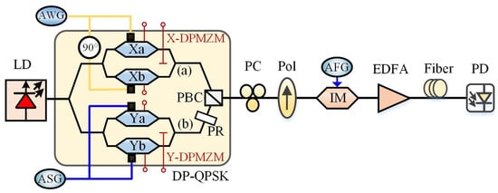
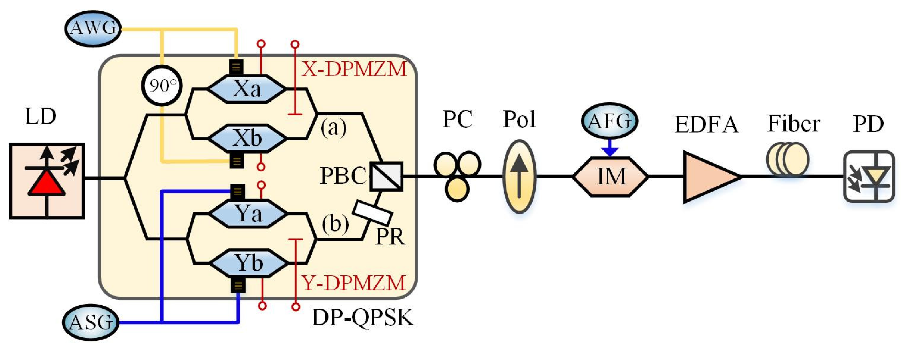
Figure 1 shows the structure of the proposed photonics-assisted radar compound jamming signal generator. An optical carrier generated through a laser diode (LD) is injected into the DP-QPSK modulator. The optical carrier with an amplitude of and an angular frequency of can be expressed as . The DP-QPSK modulator consists of two parallel DPMZMs (X-DPMZM and Y-DPMZM), a 90° polarization rotator (PR), and a polarization beam combiner (PBC). The upper X-DPMZM contains two sub-MZMs (Xa and Xb) and a main modulator. The lower Y-DPMZM contains two sub-MZMs (Ya and Yb) and a main modulator. The LFM radar signal generated by an arbitrary waveform generator (AWG) is evenly split into two paths with a phase difference of 90 degrees, and then loaded into Xa and Xb of the X-DPMZM, respectively. The three bias voltages of the X-DPMZM modulator are set to the minimum transmission point (MITP), the minimum transmission point (MITP), and the quadrature transmission point (QTP), respectively. The LFM signal can be denoted as , where , , and k represent the amplitude, frequency, and chirp rate of the LFM signal. Therefore, the output optical spectrum of X-DPMZM can be expressed as
where is the modulation index of the LFM signal, is the half-wave voltage of the modulator, and is the nth-order Bessel function of the first kind. CS-SSB modulation is achieved for the LFM signal.
Figure 1.
The diagram of our proposed photonic-assisted reconfigurable anti-dispersive radar compound jamming signal generation structure. LD, laser diode. ASG, arbitrary signal generator. AWG, arbitrary waveform generator. DP-QPSK, dual-polarization quadrature phase-shift keying. PC, polarization controller. Pol, polarizer. AFG, arbitrary function generator. EDFA, erbium-doped fiber amplifier. PD, photodetector.
The jamming seed signal generated by an ASG is evenly split into two channels and then loaded into Ya and Yb of the Y-DPMZM, respectively. The three bias voltages of the Y-DPMZM modulator are respectively set to the maximum transmission point (MATP), the MITP, and the QTP. To generate different types of compound jamming signals, we only need to change the form of the jamming seed signal loaded on the Y-DPMZM. Next, we will provide a detailed explanation of the generation principles for the CPMJ-ISRJ compound jamming signal and the FSJ-ISRJ compound jamming signal.
2.1. CPMJ-ISRJ Compound Jamming Signal Generation Principle
When the jamming seed signal loaded on the Y-DPMZM is set as a cosine signal, which can be expressed as . The output of the Y-DPMZM can be written as
where V and represent the amplitude and frequency of the jamming seed signal, respectively. is the modulation index of the jamming seed signal. Equation (2) indicates that phase modulation is achieved. Then, the output signal of the Y-DPMZM is rotated by a 90-degree polarization rotator. After being combined by the PBC, the upper and lower signals are orthogonally polarization-multiplexed at the output of the DP-QPSK modulator, and the polarization-multiplexed signal can be expressed as
Subsequently, the orthogonally polarization-multiplexed signal is transmitted through a PC and a Pol. The PC is used to adjust the polarization state of the orthogonally polarization-multiplexed signal. The polarizer combines the orthogonally polarization-multiplexed optical signal into linearly polarized light. The propagation matrix of a PC and a Pol is expressed as
where is the angle between the principal axes of the PC and the Pol, and is the phase shift induced by the PC between the X- and Y-polarized signals. Both and are adjustable from 0° to 360° by adjusting the PC. The output of the Pol can be written as
By appropriately adjusting the PC, we set as 0° and as 45°. The output linearly polarized light of the Pol can be given as
Then, this linearly polarized light is input into the IM modulator as the optical carrier. To generate interrupted sampling repeater jamming, a PRP signal is injected into the IM. The bias voltage of the IM is set at the MITP. The PRP signal can be expressed as
where , , represent the high level, the width, and the period of the rectangular pulse signal, and ∗ represents convolution. The output of IM can be derived as
where denotes the phase shift induced by the high level of the periodic rectangular pulse. Consequently, the amplitude of the optical carrier varies periodically under such modulation.
The signal sampled by the rectangular pulse is then amplified by the erbium-doped fiber amplifier (EDFA) and then passes through a SMF before being sent to the photodetector (PD) for photoelectric detection.
It is known that when a signal transmits through a dispersive device, the phase of the signal will be changed. Generally, the dispersive fiber-induced phase shift can be expressed as where is the propagation constant, and L is the length of the fiber. Expanding in the Taylor series, we have
where and are the first and second-order derivatives of with respect to the optical angular frequency. , where c is the speed of light, and D is the dispersion coefficient at . As the third and higher derivatives of are small, they are ignored. Thus, when the nth-order optical sideband whose angular frequency is transmits over a dispersive fiber, dispersion-induced phase shift can be expressed as
It can be seen from the above equations that the dispersion-induced phase shift is only related to the frequency and the length of the fiber. Therefore, after transmitting over a dispersive link, the output of the IM can be derived as
where is the phase shift introduced by the fiber dispersion at different frequencies, and all these phase shifts are relative to the optical carrier.
The is related to the dispersion coefficient, the length of the fiber, and the frequency of the radio frequency signal. After being transmitted through optical fibers, the amplitude of the radio frequency signal changes in a sinusoidal curve, which means that the power of the radio frequency signal fades periodically.
The output electrical spectrum from the PD can be expressed as
From Equation (12), it can be seen that a compound jamming signal simultaneously possesses the characteristics of both cosine phase modulation jamming and interrupted-sampling repeater jamming. Therefore, the CPMJ-ISRJ compound jamming signal can be effectively generated using the proposed approach. Moreover, the phase shift angles induced by dispersion do not affect the amplitude of the beating electrical signal (only the phase). Therefore, our proposed scheme can resist the dispersion-induced power fading effect.
2.2. FSJ-ISRJ Compound Jamming Signal Generation Principle
The jamming seed signal is set as a sawtooth wave signal, which can be expressed as
where , , and represent the amplitude, period, and fall time of the sawtooth wave, respectively. Therefore, the output of the Y-DPMZM can be expressed as
By expanding the sawtooth wave using the Fourier series, can be expressed as and . Equation (11) can be rewritten as
where represents the frequency of the sawtooth wave. In an ideal case, the fall time of the sawtooth wave is 0 s, and its amplitude of the sawtooth wave is . In this case, , and the first-order sideband is much larger than the sidebands of other orders. Thus, Equation (11) can be simplified as
The polarization-multiplexed signals output from the DP-QPSK modulator can be expressed as
The orthogonally polarization-multiplexed signals from the DP-QPSK modulator are aligned into one polarization direction after going through a PC and a Pol. In order to maximize the power of the combined signals, the angle between the orthogonally polarization-multiplexed signals and the principal axis of the Pol is set to 45°. Thus, the optical field of the combined signal can be expressed as follows:
The combined signal output from Pol is then injected into the IM modulator. The IM modulator is set at the MITP working point and driven by a periodic rectangular pulse on the RF port. The output of the IM can be derived as
where . When the high and low levels of a rectangular pulse are properly set, with the high level being and the low level being 0, it can be equivalent to interrupted sampling.
Before photoelectric conversion in the PD, the optical signal output from the IM is transmitted through the EDFA to compensate for the power loss. The signal is transmitted to the PD through an SMF. The dispersion of the optical fiber introduces a phase shift to the optical sideband. The signal before entering the PD can be represented as
where . is the phase shift introduced by the fiber dispersion at different frequencies, and all these phase shifts are relative to the optical carrier.
After photoelectric detection by the PD, the output electrical spectrum can be expressed as
From Equation (21), it can be seen that the generated compound jamming signal is based on interrupted sampling and superimposed with a frequency shift. Therefore, the FSJ-ISRJ compound jamming signal is successfully generated by our proposed approach. Moreover, the phase shift angles induced by dispersion do not affect the amplitude of the beating electrical signal (only the phase). Therefore, our proposed scheme can resist the dispersion-induced power fading effect. Furthermore, as the frequency-shifting optical carrier and the first-order radar signal sideband (both of which are negative frequency-shifting components) are beating, the generated compound jamming signal can achieve the forward movement of the false target group. When the bridge setting in the DP-QPSK is set to −90 degrees, it can generate a positive frequency shift component, enabling the backward movement of the false target group.
3. Simulation Results and Discussion
To illustrate the performance of the proposed system, we conducted simulations using VPI Transmission Maker 9.7 and MATLAB R2016a tools based on the schematic diagram in Figure 1. An LD generates continuous light waves with a power of 15 dBm and a wavelength of 1550 nm, while an AFG supplies the periodic rectangular pulse signal. The half-wave voltage of the DP-QPSK modulator is 5 V. The insertion loss and the extinction ratio are set as 6 dB and 35 dB, respectively, which are approximately the same as the parameters of the commercial DP-QPSK modulator [19,38,39,40]. The X-DPMZM is driven by an LFM signal, which has a center frequency of 8 GHz, a bandwidth of 1 GHz, and a duration of . The chirp rate of the LFM signal can be obtained as: . By properly adjusting the direct bias voltages of the X-DPMZM, the two sub-modulators and the main modulator of the X-DPMZM modulator are working at the MITP, MITP, and QTP transmission points, respectively. The two sub-modulators and the main modulator of the Y-DPMZM are working at the MATP, MITP, and QTP transmission points, respectively. At this point, the X-DPMZM can achieve CS-SSB modulation for the LFM signal, and the Y-DPMZM can achieve phase modulation for the input jamming seed signal. The jamming seed signal is generated by the MATLAB tool and then injected into the PulseArbitrSeqEl, which can generate an arbitrary electrical signal by reading from a file in the VPI. The frequency of the rectangular pulse signal is set at 2 MHz. The duty cycle is , and the high-level amplitude is 2.5 V, which corresponds to half of the half-wave voltage of the MZM. Finally, the optical signal passes through an EDFA and a length of SMF. Then the signal is sent to the PD. The EDFA operates in the automatic power control mode, and the output power is 15 dBm. According to the actual experimental instrument parameters, we set the responsivity of the PD to 0.65 A/W. The fiber dispersion coefficient is set to . After the PD beating, compound jamming signals can be generated. The electrical spectrum and waveform of the compound jamming signal output from the PD are recorded using a signal analyzer. It should be noted that when generating the CPMJ-ISRJ and FSJ-ISRJ compound jamming signal, cosine signals and sawtooth wave signals are respectively used as the seed signals. The frequency of the jamming seed signal is set to 3 MHz, and the duration is . Next, we will conduct a detailed classification simulation analysis for different scenarios, as follows.
3.1. Simulation Analysis of the Generated CPMJ-ISRJ Compound Jamming Signal
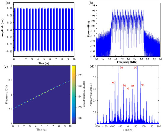
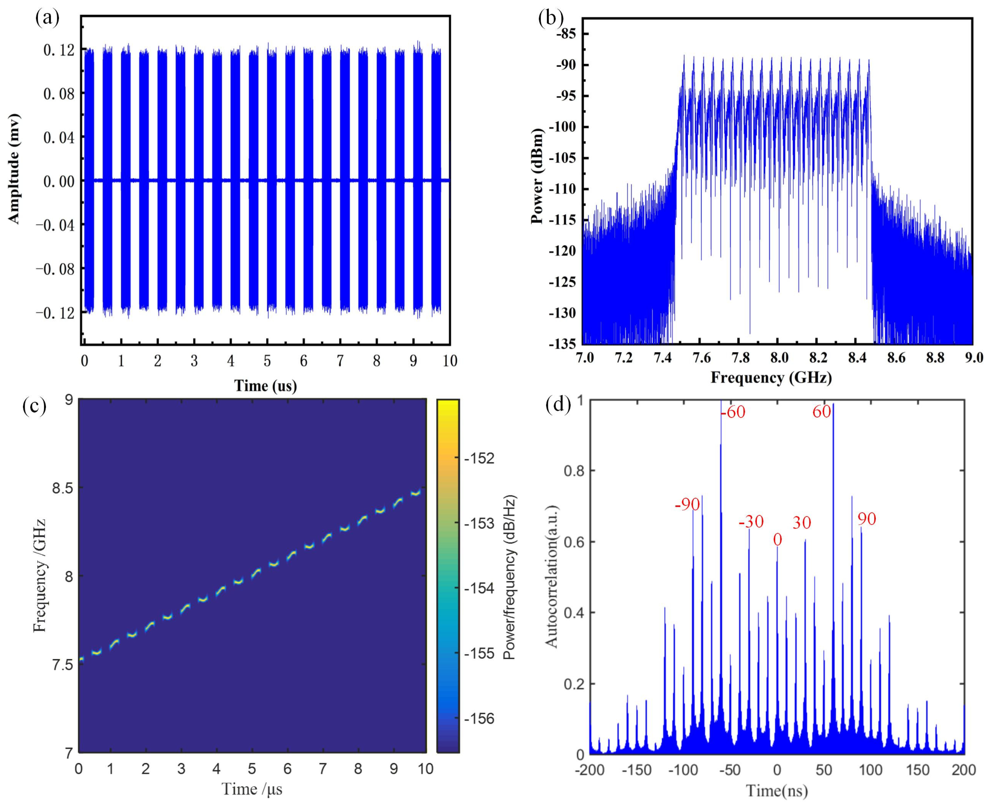
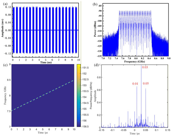
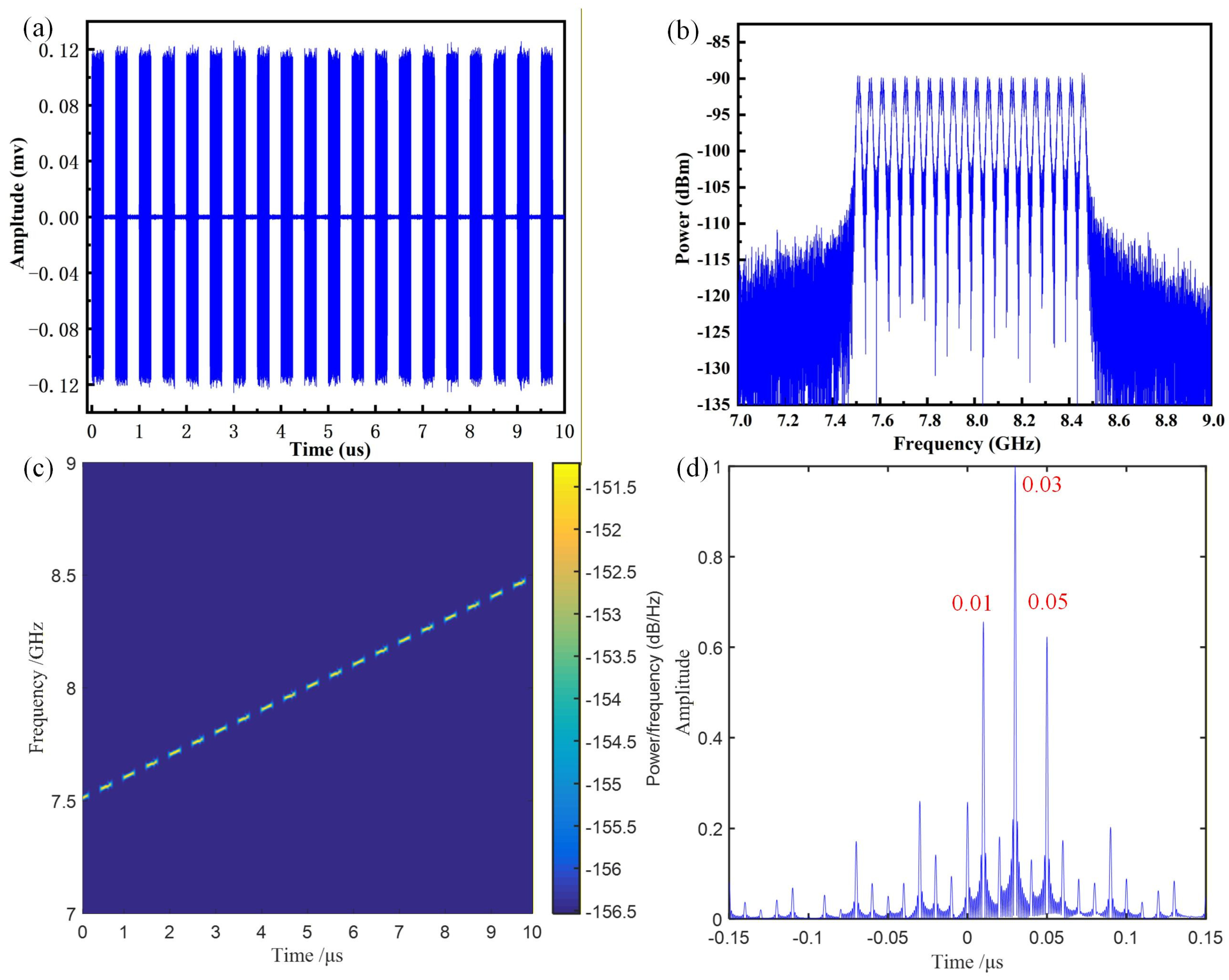
When generating a CPMJ-ISRJ compound jamming signal, the jamming seed signal driving the Y-DPMZM is set as a cosine signal with a frequency of 3 MHz and a duration of . The sampling frequency of the rectangular pulse signal driving the IM modulator is set to 2 MHz. The CPMJ-IRSJ compound jamming signal output from the PD is shown in Figure 2. Figure 2a–d respectively show the waveform diagram, spectrum diagram, time–frequency diagram, and the pulse compression result of the generated compound jamming signal. From Figure 2a,b, it can be clearly seen that the CPMJ-ISRJ compound jamming signal is uniformly sampled into 20 equal parts. From Figure 2c, it can be observed that there is a linear relationship between the time and frequency of the generated compound jamming signal. Due to the ISRJ, the generated jamming signal is divided into 20 parts, matching the 2 MHz frequency of the periodic pulse signal. Besides, due to the cosine phase modulation, the frequency of each sampling section fluctuates and exhibits a cosine variation pattern. It proves that the generated compound jamming indeed possesses both cosine phase modulation and interrupted-sampling characteristics. To verify the jamming effect, the pulse compression result of the compound jamming signal is shown in Figure 2d. It can be found that a series of false targets are generated. The positions of the main false targets should be calculated based on , corresponding to 30 ns, 60 ns, and 90 ns, respectively. Around the main false targets, a series of secondary false targets is displayed. The primary and secondary false targets are separated by a time interval of 20 ns, corresponding to the 2 MHz interrupted-sampling frequency.
Figure 2.
The simulation of the CPMJ-ISRJ compound jamming signal generated by using a cosine signal with a frequency of 3 MHz, a rectangular pulse signal with frequency of 2 MHz, and a duty cycle of . (a) waveform diagram, (b) spectrum diagram, (c) time–frequency diagram, (d) false targets generated after the CPMJ-ISRJ compound jamming signal is processed by the matched filter.
The amplitude, position, and quantity of the false targets generated by the CPMJ-ISRJ compound jamming signal are mainly determined by the frequency of the interrupted sampling signal, as well as the frequency and modulation index of the cosine phase modulation signal. Next, we conducted a detailed analysis of their influence on the pulse compression result.
- A.
- The influence of the frequency of the cosine modulation signal on the generated CPMJ-ISRJ compound jamming signal
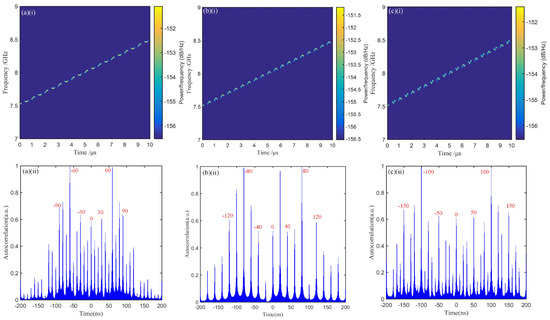
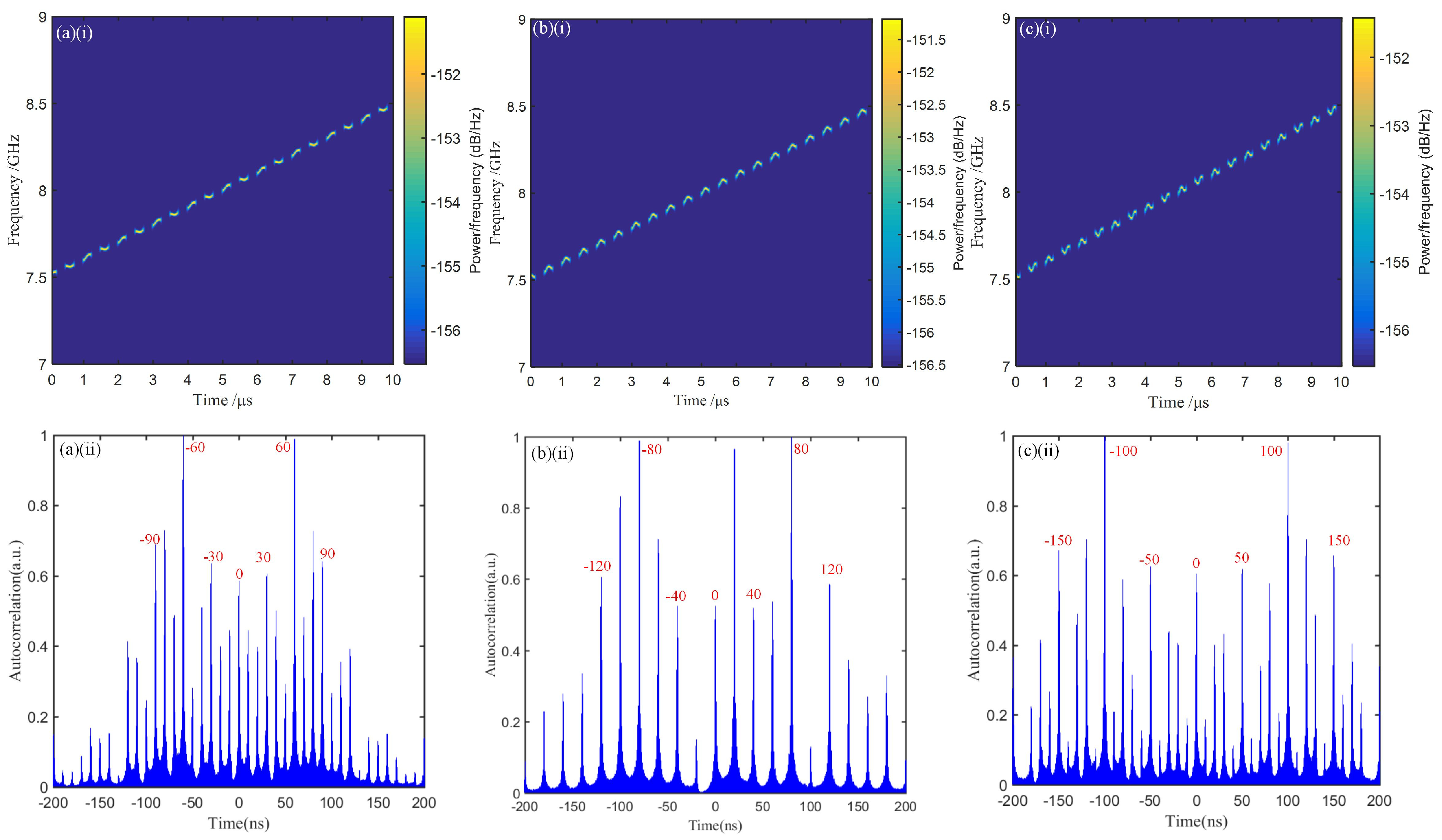
To observe the influence of the frequency of the cosine signal on the generated CPMJ-ISRJ compound jamming signal, the frequency of the cosine signal is varied among 3 MHz, 4 MHz, and 5 MHz, respectively. In this situation, the sampling frequency and duty cycle of the interrupted-sampling signal are set to 2 MHz and , respectively. The time–frequency diagrams and the pulse compression result of the generated CPMJ-ISRJ compound jamming signals are shown in Figure 3. It can be seen that the generated jamming signal is divided into 20 parts, matching the 2 MHz frequency of the interrupted-sampling signal. In addition, the frequency of each sampling section fluctuates and exhibits a cosine variation pattern because of the cosine phase modulation. What is more, with the increase in the frequency of the cosine signal, the time–frequency diagram of the compound jamming signal becomes wider. This is because the large frequency leads to large fluctuations. To verify the jamming effect, the pulse compression result of the compound jamming signal is shown in Figure 3(a(ii),b(ii),c(ii)). It can be observed that the positions of the main false targets change with the frequency of the cosine signal, responding respectively at 30 ns, 40 ns, and 50 ns, while the interval between the main and secondary false targets remains at 20 ns. The number of false targets remains unchanged. It can be seen from Figure 3(a(ii)) that in the main false target group, the amplitudes of the left and right secondary false targets are unbalanced. This is because of the superposition of the secondary false targets when the frequency of the cosine signal is an integer multiple of the sampling frequency of the interruption.
Figure 3.
The simulation of the compound jamming signal generated by using an interrupted-sampling signal frequency of 2 MHz and a duty cycle of : (a) 3 MHz CPMJ, (b) 4 MHz CPMJ, (c) 5 MHz CPMJ, (i) time–frequency diagram, (ii) pulse compression result.
- B.
- The influence of the sampling frequency of the interrupted-sampling repeater on the generated CPMJ-ISRJ compound jamming signal
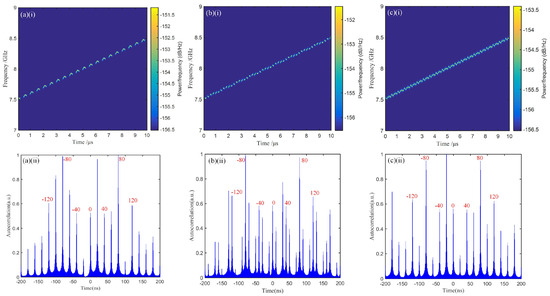
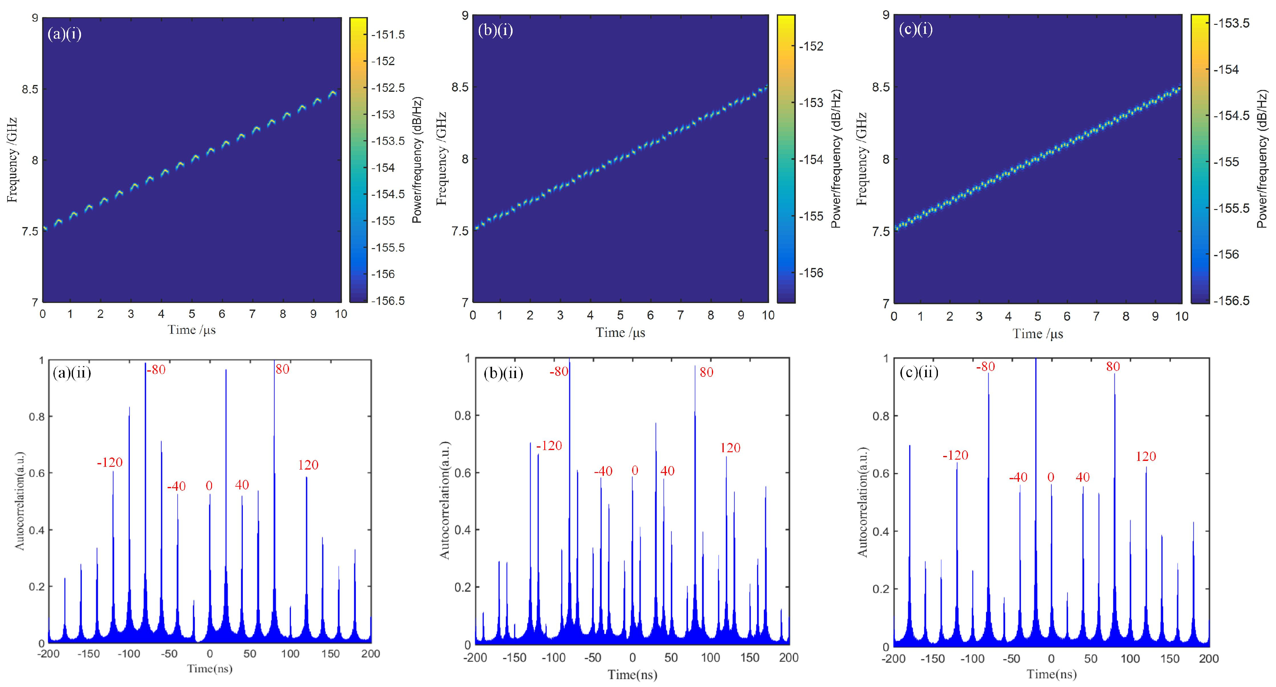
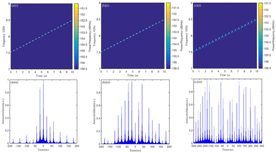
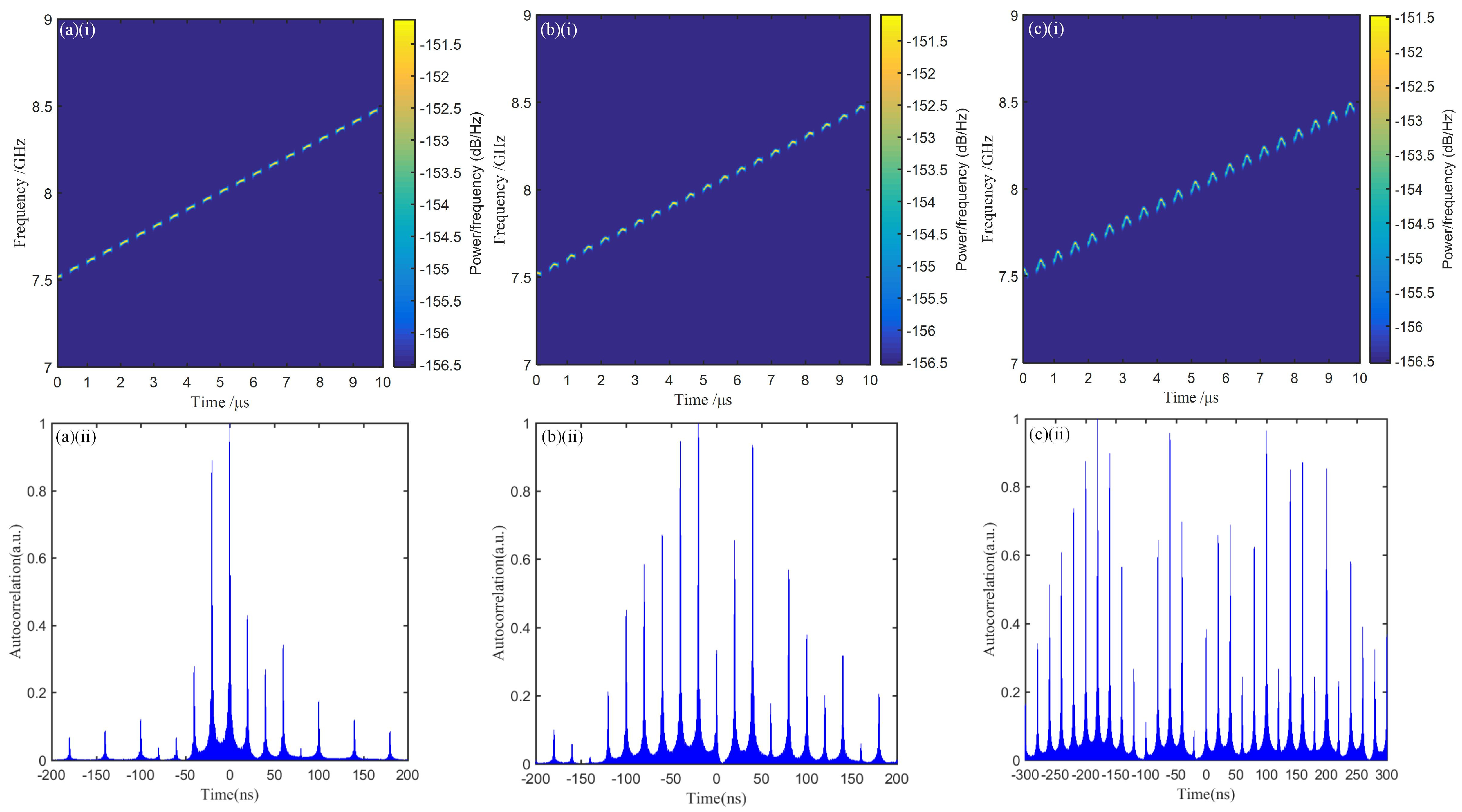
In this section, we have conducted simulation verification on the effect of the sampling frequency on the CPMJ-ISRJ compound jamming signal. The frequency of the cosine phase modulation signal is set to 4 MHz. Then, the interrupted-sampling frequencies are successively changed to 2 MHz, 5 MHz, and 10 MHz for simulation verification. A duty cycle of is configured for the interrupted-sampling signal. Figure 4 shows the time–frequency diagrams and pulse compression results of the generated CPMJ-ISRJ compound jamming signals with different interrupted-sampling frequencies. Figure 4(a(i),b(i),c(i)) are the time–frequency diagrams of the generated compound jamming signals. It can be seen that the 10 s signal was sampled 20 times, 50 times, and 100 times, respectively, matching the pulse signal frequencies of 2 MHz, 5 MHz, and 10 MHz. From Figure 4(a(ii),b(ii),c(ii)), it can be seen that the number and positions of the main false targets resulting from cosine phase modulation remain invariant with the frequency variation of the interrupted-sampling signal. The intervals between the primary and secondary false targets increase continuously with the increase in the interrupted-sampling frequency, which are 20 ns, 50 ns, and 100 ns, respectively. From Figure 4(a(ii)), it can be seen that there is an imbalance in the amplitude of the left and right secondary false targets in the main false target group. This is due to the superposition of the secondary false targets.
Figure 4.
The simulation of the compound jamming signal generated by using a cosine modulated signal with a frequency of 4 MHz and a duty cycle interrupted-sampling signal: (a) 2 MHz ISRJ, (b) 5 MHz ISRJ, (c) 10 MHz ISRJ; (i) the time–frequency diagram, (ii) the pulse compression result.
- C.
- The influence of the modulation index of cosine phase modulation on the CPMJ-ISRJ compound jamming signal
In this section, we change the modulation index of the cosine signal to 0.5, 2, and 6, respectively, to observe its influence on the generated CPMJ-ISRJ compound jamming signal. The frequency of the cosine phase modulation signal is set to 4 MHz. The sampling frequency and duty cycle of interrupted-sampling signal are also set to 2 MHz and , respectively. Finally, the time–frequency diagram and pulse compression results of the compound jamming signal are shown in Figure 5. From Figure 5(a(ii),b(ii),c(ii)), it can be seen that the position of the main false target remains unchanged, and the interval between the main and secondary false targets does not change, still being 20 ns. With the increase in the modulation index, the number of false targets significantly increases. From to , assuming a detection threshold of 0.5 [33,34], the number of false targets increases from 3 to 18. Therefore, it is verified that by increasing the modulation index, the number of false targets can be increased. However, due to the increase in the modulation index, the amplitude of the 0th order frequency component gradually decreases, and the amplitude of the higher order frequency components gradually increases. This is because when the modulation index increases to a certain extent, the value of the zeroth-order Bessel function decreases, while the values of the higher-order Bessel functions increase and are greater than that of the zeroth-order. Therefore, when using a large modulation index jamming, a larger signal-to-clutter ratio is required to achieve the same jamming effect.
Figure 5.
The simulation of the compound jamming signal generated by using a cosine modulated signal with a frequency of 4 MHz, a 2 MHz, duty cycle interrupted-sampling signal: (a) , (b) , (c) , (i) time–frequency diagram, (ii) pulse compression result.
3.2. Simulation Analysis of FSJ-ISRJ Compound Jamming Signal
In our proposed approach, the frequency-shift and interrupted-sampling compound jamming signal can be generated by changing the jamming seed signal into a sawtooth wave signal. The frequency of the sawtooth wave signal is set to 3 MHz. The frequency of the rectangular pulse signal is always set to 2 MHz. After photoelectric conversion from the PD, the waveform diagram and spectrum diagram of the output electrical signal is recorded, as shown in Figure 6a,b. It can be clearly seen that the pulse signal is sampled into 20 uniform parts, which corresponds to the 2 MHz interrupted-sampling frequency. Figure 6c more clearly shows the time–frequency characteristics of the generated FSJ-ISRJ compound jamming signal. Due to the interrupted sampling, the jamming signal is evenly divided into 20 parts. Figure 6d is the pulse compression result diagram. We find that through the frequency shift and interrupted-sampling compound jamming, a series of false targets will be generated. The main false target appears at , which corresponds to the 3 MHz frequency shift. The secondary false targets appear at approximately to the left and right of the two main false targets, and the interval between the main and secondary false targets corresponds to the 2 MHz interrupted-sampling frequency. Next, we also conducted a detailed analysis of the impact of different variables on the combined interference.
Figure 6.
The simulation of the FSJ-ISRJ compound jamming signal generated by using a frequency shift of 3 MHz, an interrupted-sampling frequency of 2 MHz, and a duty cycle of . (a) waveform diagram, (b) spectrum diagram, (c) time–frequency diagram, (d) false targets generated by the FSJ-ISRJ compound jamming signal after being processed by the matched filter.
- A.
- The influence of frequency shift on the FSJ-ISRJ compound jamming signal
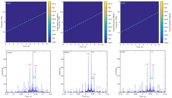
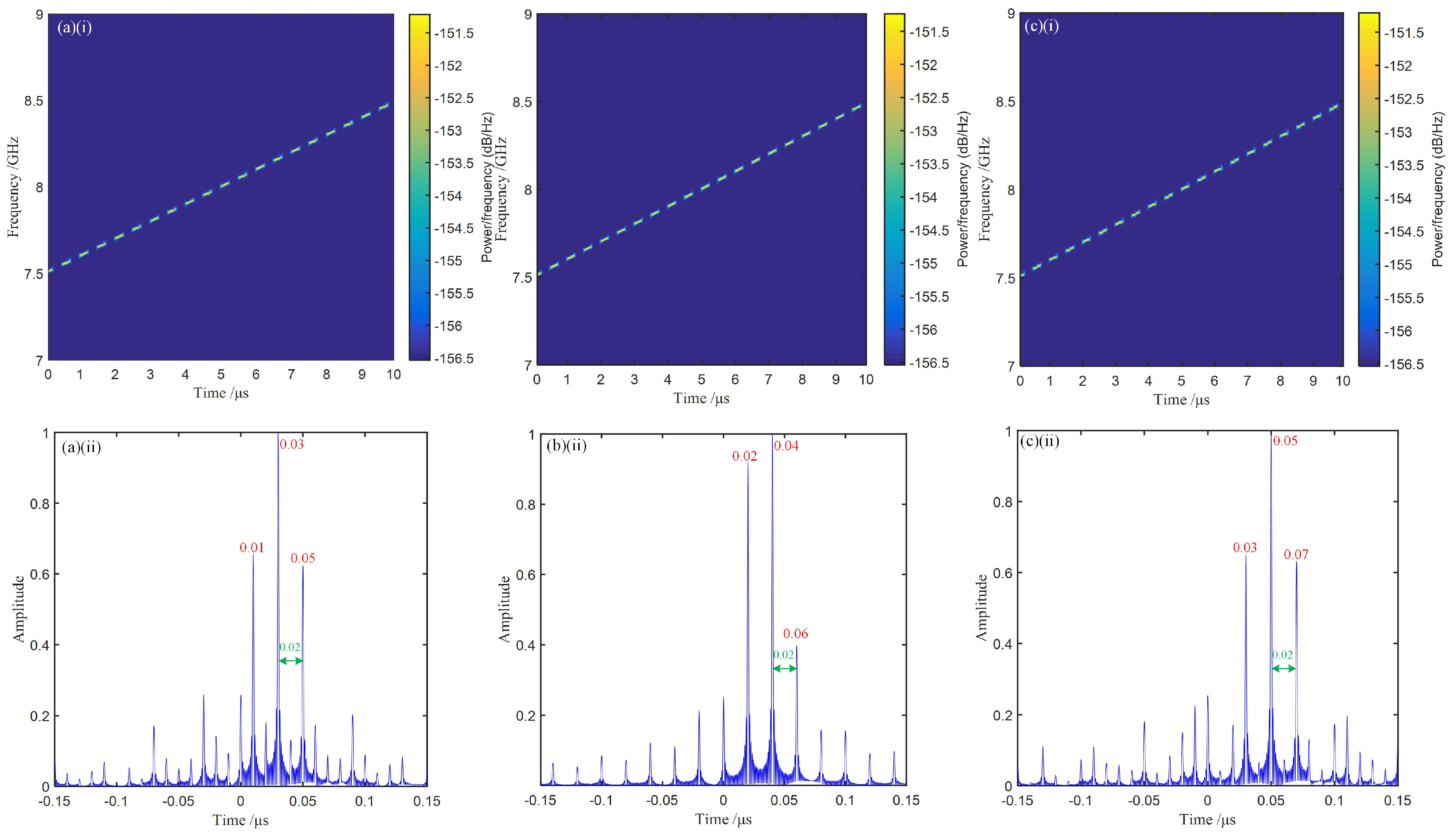
Maintain the frequency and duty cycle of the input interrupted-sampling signal at 2 MHz and , respectively. To verify the simulation, set the frequency shift to 3 MHz, 4 MHz, and 5 MHz, respectively. Figure 7 presents the time–frequency diagrams and pulse compression results of the generated FSJ-ISRJ compound jamming signals under different frequency shifts. In Figure 7(a(i),b(i),c(i)), the time–frequency diagrams of the 10 µs LFM signal are presented, including 20 interrupted samplings, matching the 2 MHz periodic sampling pulse signal frequency. From Figure 7(a(ii),b(ii),c(ii)), it can be seen that the number of false targets generated by the FSJ-ISRJ compound jamming signal remains unchanged, and the relative amplitude relationship between the false targets remains unchanged. However, as the frequency offset increases, the positions of the main false targets change to 0.03 µs, 0.04 µs, and 0.05 µs, respectively. The interval between the primary and secondary false targets remains fixed at 0.02 µs, which is determined by the interrupted-sampling frequency.
Figure 7.
The simulation of the compound jamming signal generated by using an interrupted-sampling signal with a frequency of 2 MHz and a duty cycle of : (a) 3 MHz FSJ, (b) 4 MHz FSJ, (c) 5 MHz FSJ, (i) time–frequency diagram, (ii) pulse compression result.
- B.
- The influence of the interrupted sampling frequency on the FSJ-ISRJ compound jamming signal
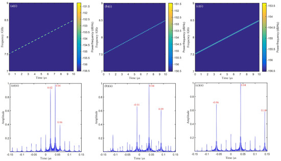
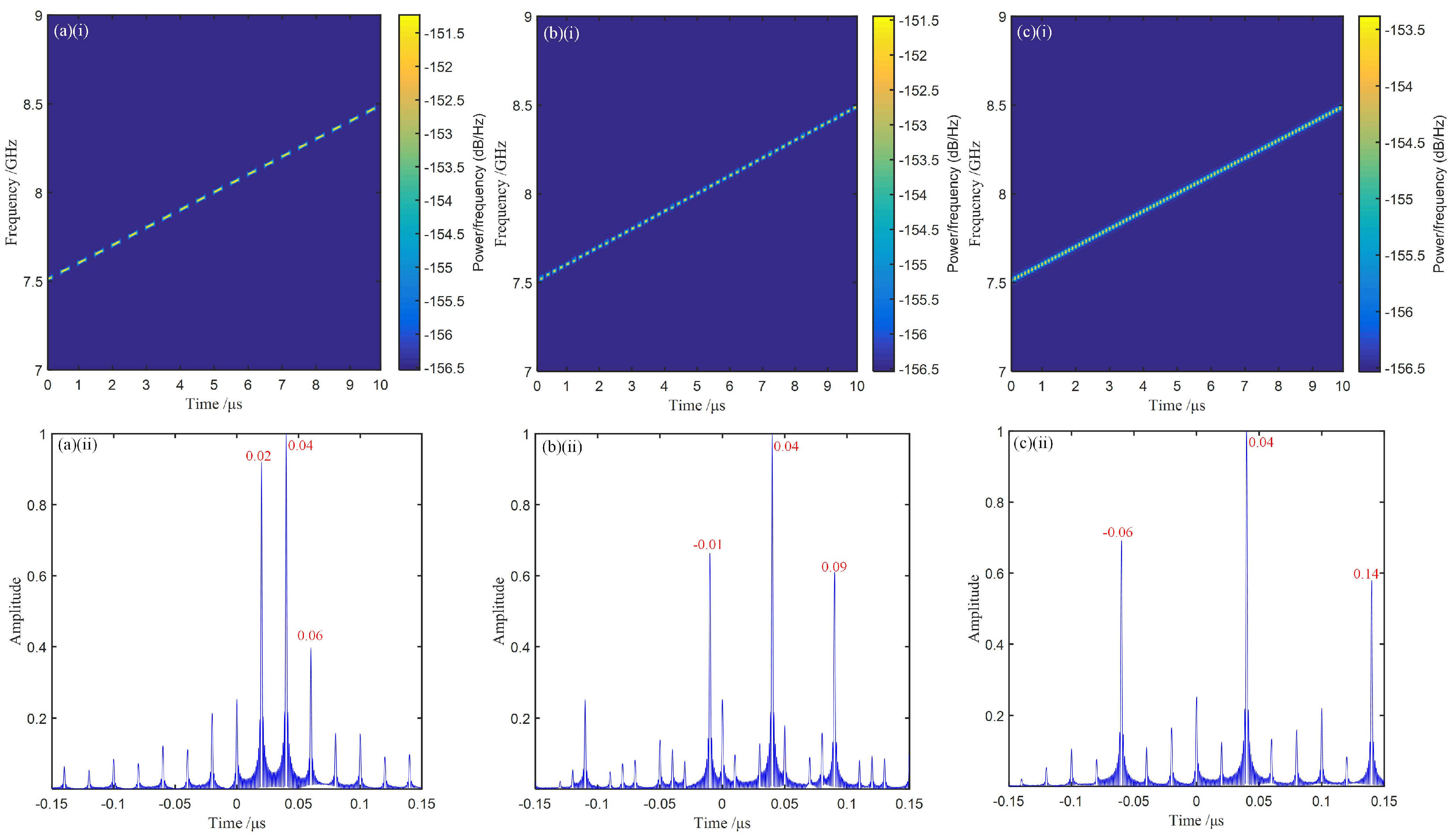
Maintain the frequency of the sawtooth wave signal and the duty cycle of the interrupted-sampling signal at 4 MHz and , respectively. To verify the influencing laws pf the interrupted-sampling frequency, we change it to 3 MHz, 4 MHz, and 5 MHz respectively. Figure 8 shows the time–frequency diagrams and pulse compression results for the compound jamming signals with varying sampling frequencies. In Figure 8(a(i),b(i),c(i)), it can be clearly seen that the pulse signal is sampled into 20, 50, and 100 uniform parts, which corresponds to the sampling frequencies of 2 MHz, 5 MHz, and 10 MHz, respectively. From Figure 8(a(ii),b(ii),c(ii)), it can be seen that the positions of the main false targets are all consistent and do not move with the change of the interrupted-sampling frequency. The interval between the primary and secondary false targets increases continuously with the increase in the interrupted-sampling frequency, and the intervals are, respectively, , , and . Furthermore, it can be seen that in Figure 8(a(ii)), the amplitudes of the secondary false targets on both sides of the main false target are not balanced. This is because the secondary false targets will overlap with each other. The 4 MHz frequency offset is exactly twice the 2 MHz interrupted-sampling frequency.
Figure 8.
The simulation of the compound jamming signal generated by using a frequency shift of 4 MHz and an interrupted-sampling signal with a duty cycle of : (a) 2 MHz ISRJ, (b) 5 MHz ISRJ, (c) 10 MHz ISRJ; (i) time–frequency diagram, (ii) pulse compression result.
4. Discussion
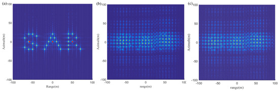
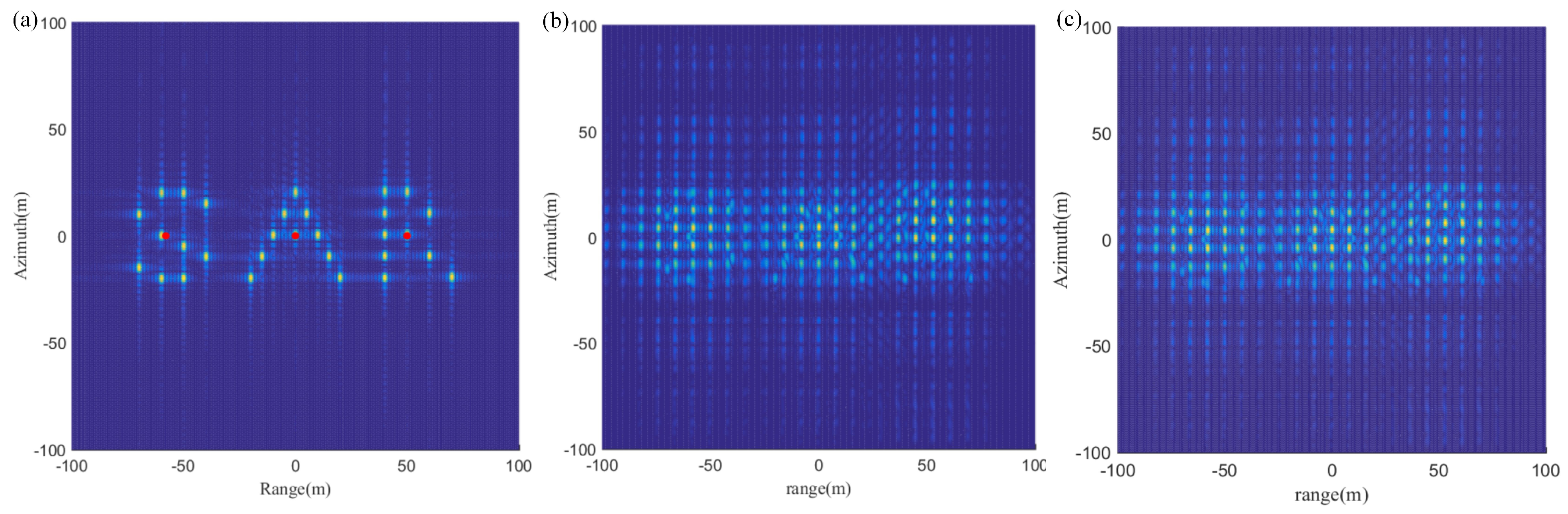
To evaluate the jamming performance of FSJ-ISRJ and CPMJ-ISRJ compound jamming, a simulation was established using MATLAB. The compound jamming effect imaging is shown in Figure 9. The imaging effect diagram of the three letters “SAR” without jamming is shown in Figure 9a. In the simulation, three radar jamming sources were set respectively at the center of the letters, as indicated by the red dots in Figure 9a. To achieve azimuth domain compound jamming, the frequencies of the compound jamming signals should be reasonably set according to the Doppler bandwidth. The frequencies of CPMJ, FSJ, and ISRJ, are set to 8 Hz, 8 Hz, and 3 Hz, respectively. The jamming is implemented concurrently in the fast-time and slow-time domains, thus generating jamming in both the range and azimuth domains. Figure 9b presents the imaging effect of the FSJ-ISRJ compound jamming. It can be seen that the letters are almost invisible after compound jamming. The imaging result with CPMJ-ISRJ compound jamming is given in Figure 9c, and also has a good compound jamming effect.
Figure 9.
The simulation results of SAR imaging (a) without jamming, (b) FSJ-ISRJ compound jamming, (c) CPMJ-ISRJ compound jamming.
The proposed structure has significant application value in the confrontation scenarios of airborne multi-mode radar, pulse Doppler radar, and air defense early warning radar. The airborne multi-mode radar has functions such as ranging, speed measurement, and direction finding. The frequency shift interrupted-sampling compound jamming can simultaneously form dual interference barriers in the distance domain and the speed domain, significantly enhancing radar target detection and ensuring the safety of our positions and combat personnel. The pulse Doppler radar relies on Doppler frequency shift to calculate the target’s speed and position, making it a key target for battlefield countermeasures. Our generated FSJ-ISRJ and CPMJ-ISRJ compound jamming signals can not only generate a large number of false targets in the distance dimension through interrupted sampling, confusing the radar’s distance gate, but can also tamper with the echo Doppler information through frequency shift modulation, preventing the radar from distinguishing between real and false targets. Therefore, the proposed scheme has potential application value in next-generation electronic countermeasures.
5. Conclusions
In this paper, a reconfigurable multi-form radar compound coherent jamming signal generator is theoretically analyzed and demonstrated through simulation. Our proposed radar compound jamming signal generator can generate not only a CPMJ-ISRJ compound jamming signal but also an FSJ-ISRJ compound jamming signal without using optical loops or filters, which provides a larger working frequency range. The simulation results show that the generated compound jamming signals have a good interference effect and can produce many false targets by adjusting the parameters reasonably. In addition, due to the CS-SSB modulation method of the radar signal, the proposed optical links can resist the chromatic dispersion-induced power fading. Furthermore, since all parameters in the system can be flexibly adjusted, such as the frequency of the periodic rectangular pulse signal and the frequency of the cosine frequency modulation signal, our proposed jamming system has flexible adjustability. Finally, our system has excellent reconfigurability and scalability. Since the Y-DPMZM can not only achieve phase modulation but also amplitude modulation, various jamming seed signals can be loaded into the modulator of the aforementioned scheme to achieve new compound jamming signals. The proposed structure has significant application value in electronic countermeasure systems.
Author Contributions
Methodology, S.L.; investigation, S.L. and H.Z.; data curation, S.L.; writing—original draft preparation, S.L.; writing—review and editing, H.Z. and Y.W.; supervision, H.Z. and Y.W.; funding acquisition, M.W. and X.Y. All authors have read and agreed to the published version of the manuscript.
Funding
This work was supported in part by the Central Government’s Fund Project for Guiding Local Science and Technology Development (No. 2025ZYDF034, No. 202502ZYDF004), and the Sichuan University of Science and Engineering 652 Scientific Research Innovation Team (No. SUSE652A006).
Data Availability Statement
Data underlying the results presented in this paper are not publicly available at this time but may be obtained from the authors upon reasonable request.
Conflicts of Interest
Hongying Zhang was financially supported by a research project grant from Sichuan Netop Telecom Corporation Limited during the completion of the present work. Mingpeng Wang and Xingmao Yan are permanent employees of Sichuan Netop Telecom Corporation Limited and receive a regular salary and related benefits from the aforementioned company. Additionally, authors Mingpeng Wang and Xingmao Yan hold patents assigned to Sichuan Netop Telecom Corporation Limited. The remaining authors declare that there are no conflicts of interest.
References
- Cohen, M. Pulse compression in radar systems. In Principles of Modern Radar; Springer US: Boston, MA, USA, 1987; pp. 465–501. [Google Scholar]
- Zhang, C.; Jiang, X.; Zhao, Y. Efficient Instantaneous Channel Propagation Modeling for Aeronautical Communications Systems with Compressed Sensing. Electron. Newsweekly 2022, 70, 670–671. [Google Scholar] [CrossRef] [Scilit]
- Skolnik, M.I. Radar Handbook. IEEE Aerosp. Electron. Syst. Mag. 2008, 23, 41. [Google Scholar] [CrossRef] [Scilit]
- Spezio, A.E. Electronic warfare systems. IEEE Trans. Microw. Theory Tech. 2002, 50, 633–644. [Google Scholar] [CrossRef]
- Yang, Y.; Zhang, W.; Yang, J. Study on frequency-shifting jamming to linear frequency modulation pulse compression radars. In 2009 International Conference on Wireless Communications & Signal Processing; IEEE: New York, NY, USA, 2009; pp. 1–5. [Google Scholar]
- Wei, X.; Jiangang, R.; Heguo, H. Combinatorial jamming of coherent radar based on DRFM. Aerosp. Electron. Warf. 2012, 2, 29–123. [Google Scholar]
- Feng, D.; Xu, L.; Pan, X.; Wang, X. Jamming wideband radar using interruptedsampling repeater. IEEE Trans. Aerosp. Electron. Syst. 2017, 53, 1341–1354. [Google Scholar] [CrossRef] [Scilit]
- Ozdil, O.; Ispir, M.; Ortatatli, I.E.; Yildirim, A. Channelized DRFM for wideband signals. In IET International Radar Conference 2015; IET: London, UK, 2015; pp. 1–5. [Google Scholar]
- Kale, A.; Thirumuru, R.; Sankara, V.; Pasupureddi, R. Wideband channelized subsampling transceiver for digital RF memory based electronic attack system. Aerosp. Sci. Technol. 2016, 51, 34–41. [Google Scholar] [CrossRef] [Scilit]
- Feng, D.; Tao, H.M.; Liu, Z.; Xiao, S.P. An approach to jamming against wide-band imaging radar using repeater. Mod. Radar 2005, 27, 19–23. [Google Scholar]
- Pace, P.E.; Fouts, D.J.; Ekestorm, S.; Karow, C. Digital falsetarget image synthesiser for countering ISAR. IEE Proc.-Radar Sonar Navig. 2002, 149, 248–257. [Google Scholar] [CrossRef] [Scilit]
- Pan, X.; Wang, W.; Feng, D.; Liu, Y.; Fu, Q.; Wang, G. On deception jamming for countering bistatic ISAR based on sub-Nyquist sampling. IET Radar Sonar Navig. 2014, 8, 173–179. [Google Scholar] [CrossRef] [Scilit]
- Liu, J.C.; Wang, X.S.; Liu, Z.; Yang, J.H.; Wang, G.Y. Preceded false target groups jamming against LFM pulse compression radars. J. Electron. Inf. Technol. 2011, 30, 1350–1353. [Google Scholar] [CrossRef] [Scilit]
- DiFilippo, D.; Geling, G.; Currie, G. Simulator for advanced fighter radar EPM development. IEE Proc.-Radar Sonar Navig. 2001, 148, 139–146. [Google Scholar] [CrossRef] [Scilit]
- Wang, X.; Liu, J.; Zhang, W.; Fu, Q.; Liu, Z.; Xie, X. Mathematic principles of interrupted-sampling repeater jamming (ISRJ). Sci. China Ser. F Inf. Sci. 2007, 50, 113–123. [Google Scholar] [CrossRef] [Scilit]
- Niu, H.; An, J.; Wu, T.; Chen, J.; Zhao, Y.; Guan, Y.L.; Di Renzo, M.; Debbah, M.; Karagiannidis, G.K.; Poor, H.V.; et al. Introducing Meta-Fiber into Stacked Intelligent Metasurfaces for MIMO Communications: A Low-Complexity Design with only Two Layers. IEEE Trans. Wirel. Commun. 2025, 25, 3016–3032. [Google Scholar]
- Ismail, A.M.; Zhao, Y.; Wang, Z.; Guan, Y.L.; Yuen, C. Visually steered reconfigurable intelligent surface-assisted mobile communications. IEEE Antennas Wirel. Propag. Lett. 2025, 24, 4497–4501. [Google Scholar] [CrossRef] [Scilit]
- Wu, Q.; Zhao, F.; Ai, X.; Liu, X.; Xiao, S. Two-dimensional blanket jamming against ISAR using nonperiodic ISRJ. IEEE Sens. J. 2019, 19, 4031–4038. [Google Scholar] [CrossRef]
- Chen, S.; Dai, D.; Li, Y.; Wang, X. The theory of 2-D cosinusoidal phase-modulated repeater scatter-wave jamming to SAR. Acta Electron. Sin. 2009, 37, 2620. [Google Scholar]
- Tai, N.; Cui, K.; Wang, C.; Yuan, N. The design of a novel coherent noise jammer against LFM radar. IEICE Electron. Exp. 2016, 13, 2138–2149. [Google Scholar] [CrossRef] [Scilit]
- Ghelfi, P.; Laghezza, F.; Scotti, F.; Serafino, G.; Capria, A.; Pinna, S.; Onori, D.; Porzi, C.; Scaffardi, M.; Malacarne, A.; et al. A fully photonics-based coherent radar system. Nature 2014, 507, 341–345. [Google Scholar] [CrossRef] [Scilit] [PubMed]
- Zhai, W.; Wang, R.; Wang, X.; Shi, F.; Pang, X.; Gao, Y.; Cui, W. Wideband Photonic Radar Target Simulator Based on All-Optical IQ Up-Converter. IEEE Trans. Microw. Theory Tech. 2025, 73, 1203–1214. [Google Scholar] [CrossRef] [Scilit]
- Zhou, S.; Sha, M.; Hu, X. Composite jamming based on comb spectrum modulation and interrupted sampling repetitive repeater. Syst. Eng. Electron. 2021, 43, 3495–3501. [Google Scholar]
- Zhu, D.; Chen, W.; Liu, S.; Yang, Y.; Liu, J.; Ye, X.; Pan, M.; Pan, S. Photonics-assisted radio frequency memory. J. Lightw. Technol. 2022, 40, 624–631. [Google Scholar]
- Nguyen, L.V.T. Photonic Radio Frequency Memory-Design Issues and Possible Solutions; DSTO Systems Sciences Laboratory: Queensland, Australia, 2003. [Google Scholar]
- Ding, Z.; Yang, F.; Zhao, J.; Wu, R.; Cai, H.; Wang, M.; Weng, Y.; Zhao, Z. Multifunctional photonic broadband RF memory for complex electronic jamming. Laser Phys. Lett. 2020, 17, 116201. [Google Scholar] [CrossRef] [Scilit]
- Ding, Z.D.; Yang, F.; Zhao, J.; Wu, R.; Cai, H.; Wang, M.; Weng, Y.; Zhao, Z. Photonic high-fidelity storage and Doppler frequency shift of broadband RF pulse signals. Opt. Exp. 2019, 27, 34359–34369. [Google Scholar] [CrossRef] [Scilit]
- Li, J.; Zheng, Q.; Yao, Y.; Lu, M.; Dong, W. A wideband tunable multi-point jamming system based on microwave photonics. Opt. Quantum Electron. 2021, 53, 106. [Google Scholar] [CrossRef] [Scilit]
- Huang, C.; Chan, E.H.W. Photonic-Assisted Microwave Frequency and Phase Shifter for Deception Jamming. IEEE Photonics J. 2021, 13, 7100110. [Google Scholar] [CrossRef] [Scilit]
- Zhang, Q.; Du, Z.; Zhao, Y.; Guan, Y.L.; Liu, J.; Yuen, C. Joint power allocation and discrete phase-shift optimization for SIM-aided ISAC systems. IEEE Trans. Veh. Technol. 2025, 74, 19795–19800. [Google Scholar]
- Zhang, C.; Jiang, J.; Zhao, Y.; Jiang, X. New Degrees of Freedom for Beamforming Manipulation in MIMO Transmission with OAM. In 2019 IEEE Globecom Workshops (GC Wkshps); IEEE: New York, NY, USA, 2020. [Google Scholar]
- Men, Y.; Wen, A.; Yang, F.; Chen, C. A photonics-assisted wideband radar jamming signal generator with flexible tunability and multi-dimensional optimization. IEEE Trans. Microw. Theory Tech. 2023, 71, 5367–5380. [Google Scholar] [CrossRef] [Scilit]
- Wang, Y.; Wen, A.; Men, Y. Tunable radar compound coherent jamming signal generation based on microwave photonics. Opt. Lett. 2023, 48, 4. [Google Scholar] [CrossRef] [Scilit]
- Men, Y.; Wen, A.; Wang, Y.; Chen, C. Photonic-assisted wideband radar jamming signal generator with flexible tunability. J. Light. Technol. 2024, 42, 6808–6815. [Google Scholar] [CrossRef] [Scilit]
- Shan, D.; Wen, A.; Men, Y.; Chen, C. Photonics-based wideband multi-format tunable radar jamming signal generator. Opt. Commun. 2024, 562, 130528. [Google Scholar] [CrossRef] [Scilit]
- Shan, D.; Wen, A.; Wang, Y.; Men, Y.; Zhang, W. Photonics-based radar compound coherent jamming generator. IEEE Photonics Technol. Lett. 2025, 37, 953–956. [Google Scholar] [CrossRef] [Scilit]
- Li, Y.; Zhao, Q.; Zhang, W. A filter-free, image-reject, sub-harmonic downconverted RoF link without fiber-dispersion-induced power fading. Photonics 2024, 11, 1191. [Google Scholar] [CrossRef] [Scilit] [PubMed]
- Gao, Y.; Liu, L.; Zhai, W.; Zhang, D.; Yang, Z.; Li, Z.; Pang, X.; Li, Y.; Cui, W. High-speed microwave photonic directional modulation for physical layer secure communication. Opt. Express 2026, 34, 12225–12241. [Google Scholar] [CrossRef] [Scilit] [PubMed]
- Zhai, W.; Zhang, D.; Wang, R.; Wu, Y.; Liu, L.; Zhong, X.; Cui, W.; Gao, Y. Ultra-Wideband Efficient Channelized Receiver Based on Photonic-Assisted Acousto-Optic Frequency Shifters. IEEE Trans. Microw. Theory Tech. 2025, 73, 6728–6737. [Google Scholar] [CrossRef] [Scilit]
- Zhai, W.; Yin, H.; Tan, J.; Li, X.; Pang, X.; Gao, Y. Unambiguous Multidimensional Microwave Parameter Measurement for Multiple Targets Based on Photonic Fractional Fourier Transform. IEEE Trans. Microw. Theory Tech. 2026, 74, 960–974. [Google Scholar] [CrossRef] [Scilit]
Disclaimer/Publisher’s Note: The statements, opinions and data contained in all publications are solely those of the individual author(s) and contributor(s) and not of MDPI and/or the editor(s). MDPI and/or the editor(s) disclaim responsibility for any injury to people or property resulting from any ideas, methods, instructions or products referred to in the content. |
© 2026 by the authors. Licensee MDPI, Basel, Switzerland. This article is an open access article distributed under the terms and conditions of the Creative Commons Attribution (CC BY) license.