Abstract
Laser-induced damage of sol–gel SiO2 antireflection coatings remains a key reliability issue in high-power laser systems because porous networks, residual hydroxyl groups, and defect-related absorption centers can trigger localized heating and stress concentration under nanosecond irradiation. In this work, continuous-wave CO2 laser conditioning was used as a localized post-treatment method to regulate the microstructure of sol–gel SiO2 coatings on fused silica substrates. The revised manuscript clarifies the processing window, scanning parameters, laser damage testing protocol, and the sample-specific nature of the reported LIDT values. Laser conditioning induces partial densification of the porous coating, dehydration of Si-OH groups, relaxation of the Si-O-Si network, and enhancement of mechanical properties. Under the optimized conditioning condition, the surface roughness decreases from 14.08 nm to 9.76 nm, and the LIDT at 1064 nm increases from 4.8 J/cm2 to 7.0 J/cm2. The LIDT values are discussed as a relative microstructure–property comparison for the present coating system rather than as the upper technological limit of sol–gel silica coatings. Combined FTIR analysis, thermal simulation, morphology observation, and damage probability analysis indicate that the improvement originates from the combined effects of reduced defect absorption, moderated porosity, improved heat dissipation, and enhanced resistance to thermally induced cracking. The results provide a mechanism-guided strategy for using CO2 laser conditioning to tune sol–gel silica coatings while also identifying the need for further validation on higher-LIDT coatings and at application-relevant wavelengths.
1. Introduction
Fused silica is widely used in high-power laser systems due to its excellent optical transparency and chemical stability across a broad spectral range [1]. To minimize Fresnel reflection losses and suppress stray light, sol–gel-derived SiO2 antireflection (AR) coatings are commonly applied to transmissive optical components [2]. However, the relatively low laser-induced damage threshold (LIDT) of these coatings remains a critical bottleneck limiting the power scalability and long-term reliability of laser systems [3]. The laser damage behavior of sol–gel silica coatings is strongly governed by their intrinsic porous microstructure. The presence of nanoscale pores, residual hydroxyl groups (Si-OH), and structural defects introduces localized absorption centers, which can lead to non-uniform energy deposition under laser irradiation. This initiates a cascade of coupled physical processes, including localized heating, thermal stress accumulation, and ultimately structural failure. Previous studies have shown that intrinsic defect populations and thermal effects play a dominant role in determining the LIDT of silica-based materials [4]. Therefore, the LIDT of such coatings is not only determined by their intrinsic material properties but also by the complex interplay between porosity, defect population, and thermal–mechanical stability [5]. It should be noted that the LIDT of sol–gel SiO2 coatings is strongly dependent on coating recipe, substrate cleaning, pore size distribution, residual hydroxyl concentration, drying/annealing history, testing wavelength, pulse width, and laser spot size. State-of-the-art sol–gel AR coatings used in large laser facilities can exhibit much higher LIDT values than those measured in the present sample set. Therefore, the purpose of this study is not to claim the highest absolute LIDT of sol–gel coatings or to imply direct equivalence to ICF-class facility optics, but to establish a mechanism-guided comparison within the same coating preparation route and to clarify how CO2 laser conditioning modifies microstructure, hydroxyl-related defects, porosity, and damage precursors.
Conventional approaches to improve the LIDT of sol–gel coatings mainly rely on high-temperature furnace annealing or optimization of the deposition process [6]. While thermal annealing can effectively reduce porosity and remove residual hydroxyl groups, it typically requires high temperatures and long processing times, which may introduce thermal stress or limit compatibility with certain substrates. In contrast, laser-based post-processing techniques, particularly continuous-wave (cw) CO2 laser conditioning, offer a localized and controllable approach for modifying material properties. Previous studies have demonstrated that CO2 laser irradiation can enhance the LIDT of fused silica substrates by mitigating surface defects and reducing absorption precursors [7]. Additionally, laser-induced thermal processes have been reported to promote densification and structural evolution in sol–gel-derived films [8]. Despite these advances, systematic investigations on sol–gel silica coatings remain limited, and the underlying mechanisms governing laser-induced microstructure evolution and damage resistance enhancement are not yet fully understood. In particular, the role of CO2 laser conditioning in tailoring the porous network structure, regulating silanol dehydration, and modifying defect-related absorption has not been quantitatively established [9]. Moreover, the correlation between laser processing parameters, microstructural evolution, and LIDT improvement remains unclear, hindering the optimization and practical application of this technique [10].
In this work, we employ a continuous-wave CO2 laser to condition sol–gel-derived SiO2 AR coatings on fused silica substrates and systematically investigate the resulting changes in morphology, mechanical properties, optical characteristics, and laser damage resistance [11,12]. By combining experimental characterization with thermal simulations, we reveal that laser-induced densification, Si-OH dehydration, and defect suppression collectively contribute to the enhancement of LIDT. This study establishes a microstructure–property relationship framework for laser-conditioned sol–gel coatings and provides a practical strategy for improving the damage resistance of optical coatings in high-power laser applications.
2. Experimental
2.1. Laser Conditioning System
The CO2 laser (ULR-50, Universal Laser Systems, Inc., Scottsdale, AZ, USA) has a wavelength of 10.6 µm. The laser spot on the sample surface was an elliptical Gaussian beam with a short-axis length of 2.30 ± 0.05 mm and a long-axis length of 2.78 ± 0.05 mm. The laser power used for conditioning ranged from 8 W to 20 W, and the scanning speed was fixed at 0.5 mm/s unless otherwise specified. Before sample processing, the CO2 laser was pre-operated at a 35% duty cycle (approximately 28 W) for 15 min to stabilize the output. The sample was mounted on a computer-controlled displacement platform, and the laser irradiation path was aligned using the visible indicator beam. To improve process reproducibility, the scanning strategy is explicitly defined. The CO2 laser conditioning was performed in a raster-scanning mode with continuous-wave irradiation during each scan line. The scan speed was 0.5 mm s−1. The line spacing between two adjacent scan lines was set to 1.0 mm, corresponding to an approximate transverse overlap of 56.5% when calculated using the 2.30 mm short-axis beam diameter, or 64.0% when calculated using the 2.78 mm long-axis beam diameter. Each sample region was scanned once unless otherwise stated. Because the CO2 laser was operated in continuous-wave mode, the longitudinal exposure was described by the effective dwell time rather than pulse-to-pulse overlap. The effective dwell time was estimated as τ = Dl/v, where Dl is the beam length along the scanning direction and v is the scan speed. Using Dl = 2.78 mm and v = 0.5 mm s−1, the effective dwell time was approximately 5.56 s for each point along the scan path. These parameters ensure sufficient thermal accumulation for microstructural relaxation while avoiding excessive ablation under the optimized 12 W conditioning condition. The schematic diagram of the experimental system is shown in Figure 1.
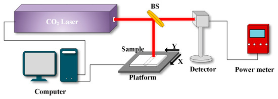
Figure 1.
Schematic of the laser conditioning setup.
The sample was fixed on the fixture of the computer-controlled displacement platform, and the laser beam was directed to the sample by the beam delivery optics. The laser indicator light was first used to align the beam with the marked region on the sample, after which laser output and platform movement were initiated synchronously. For comparison with a conventional thermal post-treatment route, another batch of samples was heated in a furnace at 800 °C for 2 h under ambient atmosphere. The LIDT of the furnace-annealed coating was measured using the same 1064 nm 1-on-1 protocol and was approximately 6.3 J cm−2. This value is higher than that of the as-deposited coating (4.8 J cm−2) but lower than that of the optimally CO2-laser-conditioned coating (7.0 J cm−2), indicating that laser conditioning provides an effective localized thermal-conditioning route rather than merely reproducing conventional furnace annealing. The result also suggests that excessive or overly uniform densification during high-temperature furnace annealing may reduce the stress-relaxation capability of porous sol–gel coatings, whereas localized CO2 laser conditioning can better balance defect suppression, moderate porosity, and mechanical stability.
2.2. Preparation of Silica Sols and Deposition
Ethyl orthosilicate (TEOS, Si(OC2H5)4, 98%, Chron Chemical, Chengdu, China), ammonia (NH3·H2O, 25–28%, Chron Chemical, Chengdu, China), and anhydrous ethanol (C2H6O, 99.7%, Chron Chemical, China) were mixed in a molar ratio of 1:2:30 to prepare a 500 mL solution. The prepared solution was first stirred in an ice water bath for 2 h and then stirred at room temperature for 3 h [13]. After that, the solution was aged at 50 °C for 5 days. The aged SiO2 sol was then filtered with a microporous filter with a pore diameter of 0.22 to remove the large agglomerated particles and dust in the sol. The fused quartz substrate was immersed in a cleaning agent for 30 min, after which it was removed and rinsed with plenty of deionized water for 2 min. This was followed by 20 min of ultrasonic cleaning at a frequency of 30 kHz and a constant temperature of 40 °C. After the completion of the ultrasonic cleaning process, the substrate is placed on a customized stand and dried with an electric fan. Coatings with thicknesses of ~170 nm (T1), ~330 nm (T2), and ~480 nm (T3) were obtained by the dip coating method with substrate withdrawal velocities of 100 mm/min. Finally, the prepared samples were dried in a vacuum drying oven (FED115, Binder, Tuttlingen, Germany) for 30 min. The whole sample preparation process was carried out in a class 100 clean room.
2.3. Characterization
The surface morphology was tested with an optical microscope (DMR, Leica Microsystems, Wetzlar, Germany). The roughness was measured using an atomic force microscope (XE 15, Park Systems, Suwon-si, Republic of Korea) with a scanning area of 25 μm2 and a scanning frequency of 0.5 Hz. At least three different locations were selected for each roughness measurement. The thickness of the coatings was measured using a probe profilometer (Dektak 150, Bruker, Ettlingen, Germany). A nanoindenter (Ti950, Bruker) was used to measure the elastic modulus and hardness. The infrared spectra of the samples were measured in reflection mode using a Fourier transform infrared (FTIR) spectrometer (Bruker VERTEX 80V, Germany) with a resolution of 0.2 cm−1. The transmission spectrum of the samples was captured by a UV-Vis spectrometer (Lambda950, PerkinElmer, Shelton, CT, USA) with a resolution of 0.08 nm. Laser-induced damage testing was performed at 1064 nm using a Q-switched nanosecond pulsed laser under a 1-on-1 protocol. The pulse width was 7 ns, and the laser beam was focused onto the coating surface at normal incidence with a Gaussian spot diameter of 320 ± 20 µm at the 1/e2 intensity level. The test procedure followed the principle of ISO 21254 for laser-induced damage threshold evaluation [14]. For each fluence level, 10 independent sites were irradiated by a single laser pulse, with a spacing of at least 1.0 mm between neighboring sites to avoid interaction between damaged regions. The fluence step was typically 0.4–0.6 J cm−2 near the transition region. After irradiation, each site was inspected by optical microscopy, and the damage probability was calculated as the ratio between damaged sites and total tested sites at the corresponding fluence. The LIDT was determined from the fitted damage probability curve. The reported thresholds are therefore specific to the present wavelength, pulse width, 1/e2 spot diameter, coating preparation route, and 1-on-1 test protocol; comparisons with literature values should be made only under similar testing conditions.
3. Results and Discussion
3.1. Microstructure Evolution and Surface Morphology
The surface morphology of the sol–gel SiO2 coatings after CO2 laser conditioning was systematically investigated to elucidate the microstructural evolution induced by laser irradiation.
As shown in Figure 2, the laser-processed regions exhibit a noticeably smoother and more compact surface compared with the as-deposited coatings, without evident signs of thermal ablation under appropriate processing conditions. This indicates that laser conditioning can effectively modify the porous microstructure while preserving the integrity of the coating. The influence of laser power on the surface morphology is further illustrated in Figure 2. At relatively low laser power (e.g., 8 W), the morphology remains largely unchanged, suggesting that the deposited energy is insufficient to induce significant structural rearrangement within the porous network. In contrast, when the laser power increases to higher levels (e.g., 24 W), clear ablation features and surface damage become observable, indicating excessive energy deposition and local overheating. These results reveal the existence of a processing window, within which laser conditioning can promote microstructural modification without triggering destructive ablation. Atomic force microscopy (AFM) measurements (Figure 2) provide quantitative insight into the surface evolution. The as-deposited coating exhibits a porous structure composed of loosely packed SiO2 nanoparticles, with a root-mean-square roughness (Rq) of 14.08 nm. After laser conditioning, the roughness decreases to 9.76 nm, accompanied by a more homogeneous surface morphology. This smoothing effect is attributed to thermally induced viscous flow and partial collapse of nanoscale pores, leading to a densification of the silica network. For comparison, furnace annealing results in an even lower roughness of 8.44 nm, which can be attributed to the more uniform thermal field and longer treatment duration.
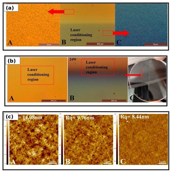
Figure 2.
Combined microstructure and morphology evolution after CO2 laser conditioning: (a) optical morphology of regions with and without laser conditioning at different magnifications; (b) morphologies obtained under different CO2 laser powers, showing the processing window and the onset of excessive ablation at high power; (c) AFM images of the as-deposited, laser-conditioned, and furnace-heated coatings, showing roughness reduction and surface densification.
This phenomenon is related to the capillary force between sol–gel particles. The liquid surface around the particles forms a meniscus under the action of gravity or the wall surface. When there are other particles around, the meniscus deforms, and its unbalanced surface tension in the horizontal direction is the transverse capillary force, as shown in Figure 3. The transverse capillary force F between two particles at the fluid interface can be described as , where is the capillary charge, L is the distance between the particles, and and are the meniscus slope angles and contact line radius, respectively. is the surface tension. With the evaporation of water, and will increase, which causes a lateral capillary force of attraction effect.
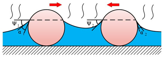
Figure 3.
Capillary-force interaction of colloidal particles during solvent evaporation.
The lateral capillary attraction between neighboring sol–gel particles increases as solvent evaporates and the interparticle distance decreases [15]. Here, the capillary interaction depends on the meniscus geometry, particle spacing, contact-line radius, and surface tension. During drying or thermal conditioning, the reduction in liquid content and the rearrangement of silica nanoparticles promote capillary-driven aggregation and network shrinkage, which provides a qualitative explanation for the observed densification and surface smoothing.
3.2. Thickness Evolution and Mechanical Properties
The evolution of coating thickness after CO2 laser conditioning was investigated to further understand the structural densification process.
As shown in Figure 4, scratches were intentionally introduced perpendicular to the laser scanning direction to create a step profile for thickness measurement. The height difference at the scratch edge corresponds to the film thickness, which was measured using a stylus profilometer. A similar method has been widely used for thin-film characterization [16]. The results indicate a clear reduction in film thickness after laser conditioning, and the shrinkage becomes more pronounced with increasing laser power. For example, under a laser power of 20 W, the thickness of the coatings decreases from 170 nm, 330 nm, and 480 nm to 140 nm, 240 nm, and 350 nm for T1, T2, and T3 samples, respectively. The higher shrinkage observed in thicker films suggests that densification is more significant when a larger porous volume is present.
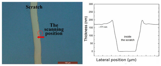
Figure 4.
Schematic of film thickness measurement and measured step-height profile. The horizontal axis is labeled as lateral position (μm) to avoid ambiguity in the profilometer profile.
As shown in Figure 5, the shrinkage increment gradually decreases with increasing laser power, indicating that the densification process approaches a saturation state. At higher laser powers, most accessible pores collapse and the structure transitions toward a compact configuration, further supporting the existence of a controllable processing window.
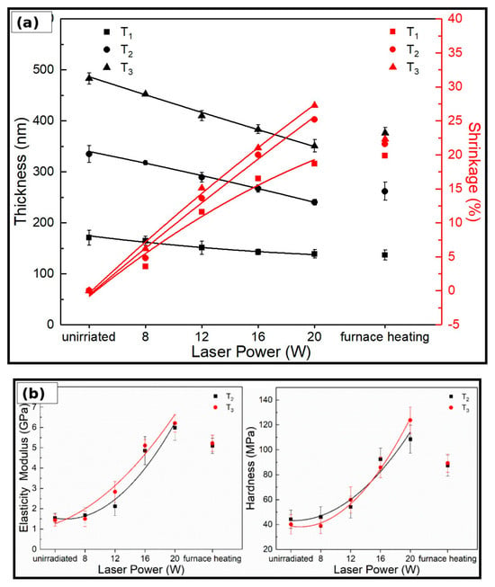
Figure 5.
Combined thickness shrinkage and mechanical-property evolution after CO2 laser conditioning: (a) variation in film thickness and shrinkage rate with laser power; (b) elastic modulus and hardness of the coatings after laser conditioning and furnace heating.
The mechanical properties of the coatings were evaluated by nanoindentation, as shown in Figure 5. Both the elastic modulus and hardness increase significantly after laser conditioning. Under 20 W irradiation, the elastic modulus reaches 4.9 GPa and the hardness increases to 85 MPa. This improvement is attributed to the collapse of the porous structure and enhanced connectivity between SiO2 nanoparticles, leading to a more rigid and stable network. From the perspective of laser damage resistance, enhanced mechanical strength improves the ability of the coating to withstand thermally induced stress and suppress crack initiation and propagation, providing a physical basis for the observed increase in LIDT.
3.3. Chemical Structure Evolution and Optical Properties
To further elucidate the mechanism underlying the laser-induced microstructural modification, Fourier transform infrared (FTIR) spectroscopy was employed to analyze the chemical structure evolution of the sol–gel SiO2 coatings.
As shown in Figure 6A, the overall spectral profiles of the coatings before and after laser conditioning remain largely unchanged, indicating that the fundamental Si-O-Si network structure is preserved. However, noticeable variations in specific absorption bands are observed, suggesting microstructural evolution. As shown in Figure 6B–D, the characteristic vibrational modes of the Si-O-Si network exhibit both intensity changes and peak shifts after laser conditioning. The rocking mode around 480 cm−1 and asymmetric stretching mode around 1120 cm−1 are clearly identified. In particular, the asymmetric stretching peak exhibits a red shift of approximately 5 cm−1 after laser treatment, as shown in Figure 6C. According to the central-force model proposed by Galeener, this shift corresponds to a decrease in the Si-O-Si bond angle and an increase in the average bond length, indicating thermally induced relaxation and rearrangement of the silica network. More importantly, the absorption band near 930 cm−1, which is associated with Si-OH bending vibrations, decreases significantly after laser conditioning. This result indicates that residual hydroxyl groups are effectively removed through thermally induced dehydration reactions. Since Si-OH groups can act as defect-related absorption centers in silica-based materials, their reduction is expected to suppress localized absorption under laser irradiation. In addition, the shoulder peak near 1230 cm−1 becomes weaker after laser conditioning. This feature is commonly attributed to the longitudinal optical component of the Si-O-Si asymmetric stretching vibration and is related to the porosity of sol–gel-derived films. The reduction in this peak suggests a decrease in film porosity, consistent with the densification behavior observed in Section 3.1 and the thickness shrinkage discussed in Section 3.2.
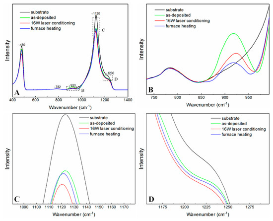
Figure 6.
(A) FTIR reflectance spectra of the as-deposited and CO2-laser-conditioned coatings. The dashed rectangles indicate the spectral regions enlarged in (B–D). (B) Enlarged view of the 740–980 cm−1 region, highlighting the Si-OH-related vibration band near 930 cm−1. (C) Enlarged view of the 1080–1180 cm−1 region, showing the Si-O-Si asymmetric stretching vibration and its peak shift after laser conditioning. (D) Enlarged view of the 1160–1300 cm−1 region, illustrating the variation of the shoulder peak associated with the longitudinal-optical component of the Si-O-Si vibration and film porosity.
To further understand the thermal processes during laser conditioning, numerical simulations were conducted using COMSOL Multiphysics. In response to the request for clearer reproducibility, the revised Table 1 separates the parameters of the fused silica substrate and the sol–gel SiO2 coating. This distinction is important because the dense substrate and porous coating have different thermal conductivities, heat capacities, densities, and absorption behaviors. In the model, the CO2 laser heating is treated as a moving heat source, and heat transfer from the substrate to the coating is considered through thermal conduction across the coating-substrate interface.

Table 1.
Parameters used in the thermal simulation.
Figure 7 shows the simulation results of the temperature distribution at different times.
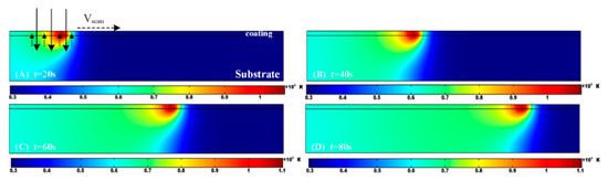
Figure 7.
Simulated thermal response during CO2 laser conditioning at 12 W and 0.5 mm s−1: temperature distribution at (A) t = 20 s, (B) t = 40 s, (C) t = 60 s, and (D) t = 80 s. High-contrast labels are used for readability. The fixed-point temperature evolution analysis shows peak temperatures of approximately 1060 K at the coating surface, 1100 K at the coating-substrate interface, and 980 K at 10 μm below the substrate surface.
As shown in Figure 7, the temperature distribution evolves significantly during laser scanning, and the maximum temperature near the coating-substrate region can reach approximately 1100 K under the simulated 12 W, 0.5 mm s−1 conditioning condition. To strengthen the quantitative analysis, temperature-time histories were extracted from three representative fixed locations: the coating surface, the coating-substrate interface, and a point 10 μm beneath the fused silica surface. The simulated peak temperatures at these locations were approximately 1060 K, 1100 K, and 980 K, respectively. The coating-substrate interface exhibits the highest temperature because fused silica absorbs the 10.6 μm CO2 laser and transfers heat to the coating by conduction. The thermal response shows three characteristic stages: rapid heating as the moving laser spot approaches the monitored location, a short high-temperature dwell period of about 4–6 s, and subsequent cooling dominated by heat diffusion into the substrate and convection to the surrounding air. The simulation supports the proposed mechanism that CO2 laser conditioning is primarily a substrate-mediated thermal process: the fused silica substrate absorbs part of the 10.6 μm radiation and transfers heat to the porous coating. This localized and transient thermal field promotes dehydration and densification without exposing the entire sample to long-duration furnace heating. As schematically illustrated in Figure 8, CO2 laser conditioning promotes the dehydration of neighboring Si–OH groups, leading to the formation of Si–O–Si bonds and the release of H2O.
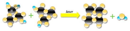
Figure 8.
Schematic showing the silanol bond dehydration with laser conditioning.
Consequently, the initially porous and loosely connected nanoparticle network transforms into a more compact and homogeneous structure with reduced defect density. Furthermore, the optical properties of the coatings were evaluated by transmission measurements. As shown in Figure 9, the coated samples exhibit high transmittance in the wavelength range of 300–1100 nm, with a maximum around 1064 nm.
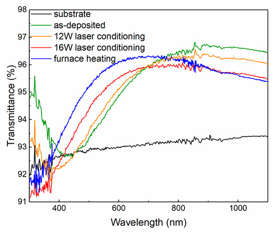
Figure 9.
Transmittance spectra of the samples subjected to laser conditioning and furnace heating.
After laser conditioning, the transmission peak shifts slightly toward shorter wavelengths, which can be attributed to the reduction in optical thickness caused by film shrinkage. Similar thickness-dependent spectral shifts have been reported in previous studies [17]. From a physical perspective, the combined reduction in porosity and defect-related absorption leads to a more uniform spatial distribution of absorbed energy under laser irradiation. This effectively suppresses the formation of localized thermal hotspots. Together with the enhanced thermal transport and mechanical stability discussed in Section 3.1 and Section 3.2, these effects provide a comprehensive explanation for the improved laser damage resistance of the coatings after CO2 laser conditioning.
4. Laser Damage Behavior and Mechanism
The laser-induced damage behavior of the coatings was evaluated using a 1064 nm nanosecond pulsed laser. The testing was performed using a 1-on-1 protocol, and the corresponding damage morphology and probability curves are presented in Figure 10 and Figure 11. The revised manuscript further clarifies the test conditions and avoids overinterpreting the absolute threshold values without considering pulse width, spot size, and defect statistics. Before discussing the improvement ratio, it is necessary to clarify the relatively low baseline LIDT of the as-deposited coating. The initial threshold of 4.8 J/cm2 is lower than values reported for optimized sol–gel silica coatings used in large high-power laser facilities. This difference may arise from the specific coating recipe, pore network, residual hydroxyl content, drying route, substrate cleaning level, coating thickness, and measurement protocol used in this study. Therefore, the improvement from 4.8 J/cm2 to 7.0 J/cm2 should be interpreted as an internal comparison within the same sample preparation route rather than as evidence that the conditioned coating reaches the state-of-the-art damage resistance of mature facility-grade coatings. This clarification has been added to improve the scientific rigor of the claim.
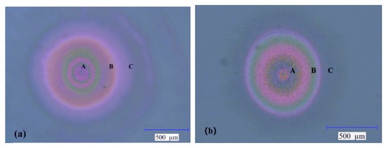
Figure 10.
Damage morphologies of SiO2 coatings: (a) as-deposited sample damaged at 7.5 J cm−2 and (b) CO2-laser-conditioned sample damaged at 9.1 J cm−2. Regions A, B, and C indicate the central ablation region, resolidified/redeposited region, and outer delamination region, respectively.
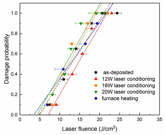
Figure 11.
Laser damage probability with different laser conditioning.
A concise literature comparison is also useful for positioning the present result. Under nanosecond irradiation at 1064 nm, optimized facility-grade sol–gel SiO2 AR coatings and carefully prepared silica-based optical coatings reported in the literature can reach substantially higher LIDT values than the present sample set, depending strongly on coating recipe, porosity, cleaning protocol, spot size, and damage-test definition. In this context, the present 4.8–7.0 J cm−2 range should be viewed as a controlled, sample-specific demonstration of relative LIDT enhancement after CO2-laser post-treatment. The main contribution is therefore the microstructure-regulation methodology and the related mechanism linking Si-OH removal, moderate densification, thermal response, and mechanical stabilization, rather than the absolute threshold value itself.
For comparison with conventional thermal treatment, furnace annealing at 800 °C for 2 h produced a lower surface roughness than laser conditioning, indicating stronger or more uniform thermal smoothing. However, roughness alone is not sufficient to determine laser damage resistance because LIDT is controlled by the combined effects of residual defects, porosity, stress-relaxation capability, and mechanical stability. The measured LIDT of the furnace-annealed coating was approximately 6.3 J cm−2, which is higher than that of the as-deposited coating but lower than that of the coating conditioned by the optimized 12 W CO2 laser process. This comparison indicates that conventional furnace annealing can reduce some defect-related absorption centers and improve the coating compactness, but the optimized CO2 laser treatment provides a more favorable balance between defect suppression and residual porosity. Therefore, the advantage of CO2 laser conditioning lies not simply in reducing roughness or increasing density, but in achieving localized and controllable microstructure regulation.
As shown in Figure 10a, the as-deposited coatings exhibit typical defect-initiated damage characteristics. The damage morphology consists of a central ablation region (region A), where the laser energy is concentrated, surrounded by a resolidified zone (region B) formed by molten material ejection and redeposition, and an outer delamination region (region C). Such features are commonly associated with micro-explosive damage triggered by localized absorption centers, as reported in previous studies [18,19]. After CO2 laser conditioning, as shown in Figure 10b, the damaged region becomes significantly smaller, and the extent of material redistribution is reduced. This indicates that the density and activity of damage precursors are effectively suppressed. In addition, the reduced damage features in the peripheral region suggest improved resistance to shock-induced deformation, which can be attributed to enhanced mechanical properties of the coating after laser treatment.
The quantitative analysis of damage probability is shown in Figure 11. The LIDT increases from 4.8 J/cm2 for the as-deposited coatings to 7.0 J/cm2 after laser conditioning at 12 W, corresponding to an improvement of approximately 46%. The improvement is most pronounced at 12 W, while higher or lower conditioning powers provide less benefit. This non-monotonic trend indicates that CO2 laser conditioning does not simply improve LIDT by monotonically increasing coating density. Instead, an optimal processing window exists in which absorbing defects are reduced and mechanical stability is improved while sufficient porosity remains to accommodate stress [20].
In the as-deposited coatings, pores and hydroxyl-related defects cause localized absorption and nonuniform energy deposition under 1064 nm nanosecond irradiation. These local hot spots generate steep temperature gradients and thermal stress, ultimately leading to micro-explosive damage and coating delamination. After CO2 laser conditioning, FTIR analysis indicates a reduction in Si-OH groups, which directly decreases defect-related optical absorption and suppresses initial hot-spot formation [21]. Thickness shrinkage and roughness reduction indicate partial densification of the porous network, which improves interparticle connectivity and thermal transport. Nanoindentation results show increased hardness and elastic modulus, suggesting stronger resistance to thermally induced cracking and delamination. Among these factors, the reduction in Si-OH-related absorption is likely the primary trigger for lowering local heat generation, while densification and mechanical strengthening provide secondary but important contributions by improving heat spreading and damage tolerance. However, excessive densification may reduce the stress-relaxation capacity of the sol–gel network. Therefore, the optimized 12 W condition is interpreted as a balanced state rather than the densest possible structure [22]. This interpretation addresses the porosity-conductivity trade-off: the treatment partially reduces harmful pore/defect populations and improves thermal-mechanical stability, but does not fully eliminate the porous architecture that is beneficial for stress accommodation in sol–gel AR coatings.
5. Conclusions
This work investigates CO2 laser conditioning as a localized post-treatment strategy for regulating the microstructure and damage resistance of sol–gel SiO2 coatings. The LIDT at 1064 nm increases from 4.8 J/cm2 to 7.0 J/cm2 under the optimized conditioning condition, corresponding to an improvement of approximately 46% within the present coating system. The revised manuscript clarifies that the absolute LIDT values are lower than those of highly optimized facility-grade sol–gel coatings and should therefore be interpreted as a sample-specific demonstration of the microstructure–property relationship rather than a technological upper limit. CO2 laser conditioning induces partial densification of the porous network, dehydration of Si-OH groups, suppression of defect-related absorption, and enhancement of mechanical stability. These changes collectively reduce local hot-spot formation, improve heat dissipation, and increase resistance to thermally induced cracking. The results reveal that laser damage resistance is governed by the coupling among porosity, defect absorption, thermal transport, and mechanical response and that an optimal porosity regime rather than maximum densification is required. The major contribution of the work is the demonstration of a localized post-treatment methodology for regulating coating microstructure and damage precursors. Future studies should verify the approach on facility-grade high-LIDT sol–gel coatings and under application-relevant wavelength, pulse-duration, and beam-size conditions.
Author Contributions
Investigation, C.H.; formal analysis, K.L.; validation, Z.L.; resources, Y.W.; supervision, J.H. All authors have read and agreed to the published version of the manuscript.
Funding
National MCF Energy R&D Program (2024YFE03190004); Innovation Center for Special Optical Glass Materials Technology (CXZX-TZGXBL-KYJJ-2025-06); Sichuan Science and Technology Program (2024YFFK0048, 2024ZYD0275).
Data Availability Statement
The data supporting the findings of this study are available from the corresponding author upon reasonable request.
Conflicts of Interest
CDGM Glass Co., Ltd. provided technical support and experimental resources for this study but had no role in the study design, data collection, data analysis, interpretation of results, manuscript preparation, or the decision to publish the results.
References
- Liu, H.; Wang, B.; Miao, X.; Xu, M.; Liu, X.; Zhang, F.; Jiang, Y. Behavior of 355 nm laser-induced damage growth in fused silica. Opt. Laser Technol. 2023, 158, 108847. [Google Scholar] [CrossRef]
- Law, A.M.; Bukhari, F.; Jones, L.O.; Isherwood, P.J.; Walls, J.M. Multilayer antireflection coatings for cover glass on silicon solar modules. IEEE J. Photovolt. 2022, 12, 1205–1210. [Google Scholar] [CrossRef]
- Baqiah, H.; Kechik, M.M.A.; Al-Gaashani, R.; Al-Zahrani, A.A.; Al-Hada, N.M.; Zhang, N.; Xu, S. Effects of annealing temperature on the phase formation, optical, photoluminescence and magnetic properties of sol-gel YFeO3 films. Ceram. Int. 2023, 49, 600–606. [Google Scholar] [CrossRef]
- Kiedrowski, K.; Jupe, M.; Ehlers, H.; Kennedy, M.; Wienke, A.; Ristau, D. Challenges in the development of a reliable cw-LIDT measurement routine. Opt. Mater. Express 2023, 13, 1712–1725. [Google Scholar] [CrossRef]
- Zhou, L.; Jiang, Y.; Wei, H.; Zhang, P.; Pan, X.; Fan, W.; Li, X. Laser-induced damage resistance enhancement of fused silica optics by rapid laser micromachining. In High Power Lasers and Applications; SPIE: Bellingham, WA, USA, 2021; Volume 11777. [Google Scholar]
- Tao, X.Y.; Fsaifes, I.; Koncar, V.; Dufour, C.; Lepers, C.; Hay, L.; Capoen, B.; Bouazaoui, M. CO2 laser-induced crystallization of sol-gel-derived indium tin oxide films. Appl. Phys. A 2009, 96, 741–749. [Google Scholar]
- Li, A.; Wang, Z.; Liu, J.; Zeng, X.; Wang, C.; Chen, H. Fabrication of SiO2-TiO2 strip waveguides by laser direct writing. In Proceedings of SPIE—The International Society for Optical Engineering; SPIE: Bellingham, WA, USA, 2008; Volume 6825. [Google Scholar]
- Yu, Z.; Zhao, J.; Liu, J.; Mou, Y.; Chen, M.; Peng, Y. Heat-conducting LSN: Ce-in-glass film on AlN substrate for high-brightness laser-driven white lighting. Ceram. Int. 2022, 48, 36531–36538. [Google Scholar] [CrossRef]
- Fogleman, E.A.; Kelly, M.T.; Grubbs, W.T. Laser interferometric method for measuring linear polymerization shrinkage in light-cured dental restoratives. Dent. Mater. 2002, 18, 324–330. [Google Scholar] [CrossRef] [PubMed]
- Shen, N.; Matthews, M.J.; Elhadj, S.; Miller, P.E.; Nelson, A.J.; Hamilton, J. Correlating optical damage threshold with intrinsic defect populations in fused silica as a function of heat treatment temperature. J. Phys. D Appl. Phys. 2013, 46, 165305. [Google Scholar]
- Galeener, F.L. Erratum: Band limits and vibrational spectra of tetrahedral glasses. Phys. Rev. B 1979, 20, 4382. [Google Scholar] [CrossRef]
- Shimada, Y.; Okuno, M.; Syono, Y. An X-ray diffraction study of shock-wave-densified SiO2 glasses. Phys. Chem. Miner. 2002, 29, 233–239. [Google Scholar] [CrossRef]
- Innocenzi, P. Infrared spectroscopy of sol-gel-derived silica-based films: A spectra-microstructure overview. J. Non-Cryst. Solids 2003, 316, 309–319. [Google Scholar] [CrossRef]
- ISO 21254-2:2011; Lasers and Laser-Related Equipment—Test Methods for Laser-Induced Damage Threshold—Part 2: Threshold Determination. International Organization for Standardization (ISO): Geneva, Switzerland, 2011.
- Paneerselvam, E.; Vasa, N.J.; Nakamura, D.; Palani, I.A.; Higashihata, M.; Ramachandra, R.M.C.; Tiju, T. Pulsed laser deposition of SiC thin films and influence of laser-assisted annealing. Mater. Today Proc. 2021, 35, 312–317. [Google Scholar] [CrossRef]
- Xu, C.; Xiao, Q.; Ma, J.; Jin, Y.; Shao, J.; Fan, Z. High temperature annealing effect on structure, optical property and laser-induced damage threshold of Ta2O5 films. Appl. Surf. Sci. 2008, 254, 6554–6559. [Google Scholar] [CrossRef]
- Wang, X.; Wu, G.; Zhou, B.; Shen, J. Improvement on laser-induced damage threshold of sol-gel ZrO2 coatings by crystal structure tuning. Opt. Express 2012, 20, 24482–24487. [Google Scholar] [CrossRef] [PubMed]
- Han, J.; Zhang, Q.; Fan, W.; Feng, G.; Li, Y.; Wei, A.; Hu, R.; Gu, Q. The characteristics of Ta2O5 films deposited by radio frequency pure oxygen ion assisted deposition technology. J. Appl. Phys. 2017, 121, 065302. [Google Scholar] [CrossRef]
- Majumdar, A. Microscale heat conduction in dielectric thin films. J. Heat Transf. 1993, 115, 7–16. [Google Scholar] [CrossRef]
- Xia, Z.; Xu, Q.; Guo, P.; Wu, R. Laser-induced damage characteristic of porous alumina optical films. Opt. Commun. 2011, 284, 4033–4037. [Google Scholar] [CrossRef]
- Wu, S.; Zhang, H.; Wang, H. Effect of porosity on the laser-induced damage threshold of porous anodic alumina films. Optik 2013, 124, 3246–3249. [Google Scholar] [CrossRef]
- Li, X.; Zou, L.; Wu, G. Laser-induced damage on ordered and amorphous sol-gel silica coatings. Opt. Mater. Express 2014, 4, 2478–2483. [Google Scholar] [CrossRef]


Disclaimer/Publisher’s Note: The statements, opinions and data contained in all publications are solely those of the individual author(s) and contributor(s) and not of MDPI and/or the editor(s). MDPI and/or the editor(s) disclaim responsibility for any injury to people or property resulting from any ideas, methods, instructions or products referred to in the content. |
© 2026 by the authors. Licensee MDPI, Basel, Switzerland. This article is an open access article distributed under the terms and conditions of the Creative Commons Attribution (CC BY) license.