


Abstract
This study proposes and numerically investigates the design and characterization of a ring-assisted (RA) fiber supporting 11 LP mode groups and a concentric-ring-assisted (CRA) fiber supporting 13 LP mode groups. Based on the relationship between the normalized frequency and the number of LP modes, a step-index (SI) fiber capable of supporting 13 LP mode groups is first designed. By leveraging the overlap between the high-index ring-assisted structure and the LP22 mode, the effective index difference (Δneff) between the LP22 and LP03 modes is enhanced. The resulting RA 11-LP mode fiber achieves a minimum effective index difference Min|Δneff| of 0.78 × 10⁻³, comparable to that of a standard SI 4-mode fiber, and a minimum effective area Min|Aeff| of 164 μm2, which effectively suppresses nonlinear effects. Furthermore, by introducing a second ring structure to form a CRA design, we realize a 13-LP mode fiber. This structure selectively increases the effective index of the LP61 mode through overlap with its power distribution, while leaving the effective index of the LP13 mode unaffected. The CRA 13-LP mode fiber exhibits highly stable effective indices across the C band. It demonstrates a Min|Δneff | of 0.55 × 10⁻³, which ensures effective mode separation and reduced inter-mode crosstalk. The Min|Aeff| is 131 μm2—still above 100 μm2—thereby mitigating nonlinear impairments. With support for 46 spatial modes in total, this fiber significantly enhances transmission capacity.
1. Introduction
With the advancement of optical communication, there is a growing demand for higher transmission capacity [1,2]. To address this, techniques such as polarization division multiplexing (PDM) [3], wavelength division multiplexing (WDM) [4], optical time-division multiplexing (OTDM) [5], and space-division multiplexing (SDM) [6,7,8,9] have been developed. As the first three approaches near full utilization, SDM has attracted significant attention for its potential to greatly improve communication within a single fiber [10,11,12,13]. Among SDM strategies, mode-division multiplexing (MDM) stands out for its ability to substantially increase capacity by enabling simultaneous transmission over multiple modes [14,15,16,17,18,19,20,21,22]. This has also spurred the development of multi-input multi-output (MIMO) technology [23,24,25]. However, as the number of modes increases, so do the cost and complexity of MIMO-based digital signal processing.
MDM has been widely implemented using weakly coupled step-index few-mode fibers (SI-FMFs), which reduce reliance on MIMO processing [26,27,28,29,30]. Studies have shown that increasing the effective index difference (Δneff) between modes can effectively suppress inter-mode crosstalk (IM-XT) [31,32,33]. For instance, SI-FMFs supporting four LP modes have been successfully fabricated, enabling 100 Gbps transmission over two degenerate LP11 modes across 40 km [34]. These fibers exhibit a minimum effective index difference (Min|Δneff|) of 0.8 × 10⁻³, allowing error-free decoding after 40 km of transmission. Ring-assisted (RA) structures offer several advantages, including relatively weak mode coupling among high-order azimuthal modes, which simplifies digital signal processing; a large effective area to mitigate nonlinear effects; and theoretically uniform optical amplifier gain across modes [35,36,37,38,39].
Previous studies have indicated that increasing the inter-modal effective index gap can enhance mode separation and reduce coupling, thereby improving transmission stability [40,41,42,43]. It has been demonstrated that ring-assisted fibers supporting four LP modes can achieve a minimum effective index difference (Min|Δneff|) as high as 1.8 × 10⁻³, which significantly suppresses IM-XT [44]. Experimental results confirm that the high-index ring maintains signal integrity without additional distortions. These findings underscore the effectiveness of RA structures in strategically controlling refractive index distributions [45,46]. By utilizing multiple ring-assisted regions or ellipse-assisted designs [46], it becomes feasible to support a greater number of LP or OAM modes, significantly enhancing transmission capacity [47,48]. Although current RA fibers generally support limited spatial modes, advanced designs—including graded-index ring-core and W-type structures—are essential to further scale mode density and improve bandwidth in future optical communication systems [48,49].
In this paper, we present the design and characterization of an RA fiber supporting 11 LP mode groups and a CRA fiber supporting 13 LP mode groups. To ensure sufficient mode support, we used the normalized propagation constant and a normalized frequency to determine fiber parameters capable of sustaining 13 LP mode groups. The high-index ring-assisted structure is then employed to selectively adjust modal effective indices. By optimizing the overlap between the RA structure and the LP22 mode’s power profile, the effective index of LP22 is raised while that of LP03 remains largely unaffected. Compared to a conventional SI four-mode fiber, the proposed RA structure maintains a similar Min|Δneff| of 0.78 × 10⁻³ and a Min|Aeff| of 164 μm2, effectively curbing nonlinearity while significantly increasing the number of modes.
Building on this, a second high-index ring is introduced to form a CRA structure. Through overlap with the power distribution of the LP61 mode, its effective index is increased without affecting the LP13 mode, thereby realizing a 13-LP mode fiber. The CRA fiber exhibits highly stable effective indices across the C band, with a Min|Δneff| of 0.55 × 10⁻³ and a Min|Aeff| of 131 μm2. It successfully supports 13 LP mode groups, substantially improving fiber transmission capacity.
2. Design Principle and Approach
In multimode optical fibers, mode coupling often occurs, leading to scattering losses. To minimize the mode coupling coefficient, the expression for this coefficient is given as follows:
where ω is angular frequency, ε0 is vacuum permittivity, ncore is the core refractive of a vacuum, nclad is the cladding refractive of a vacuum, a is the radius of the core, P is the optical power, and (a) and Eq(a) represent the optical field of different modes at the core–cladding interface. f(z)cos(mϕ + ψ) is the fluctuation compared with the ideal waveguide. is the geometric factor related to the spatial distribution of mode fields and fiber deformation. The power coupling coefficient can be expressed as the following:
where F(Δβpq) is the power spectrum density of f(z) at frequency Δβpq. hpq depends on Δneff or on the micro-bends. For FMFs, there is a threshold point called . When Δneff < , hpq decreases with the increase in Δneff. When Δneff > , hpq is approximated by a constant. The numerical value of hpq is often limited by the intrinsic distortions in the manufacturing process. When FMFs are subjected to significant winding tension, a higher Δneff is required to suppress the hpq between modes. Consequently, to mitigate the adverse effects of random perturbations while expanding the mode-supporting capacity, it is critical to maximize Δneff during the fiber design process to ensure robust modal isolation.
In the fiber design process, it is essential to first define the core radius and the refractive index of the cladding as foundational parameters. In the design of SI fibers, the normalized propagation constant b and the normalized frequency V are employed as key parameters to characterize the modal behavior. These two parameters are defined by the following expressions:
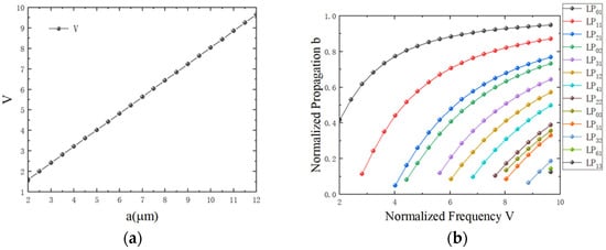
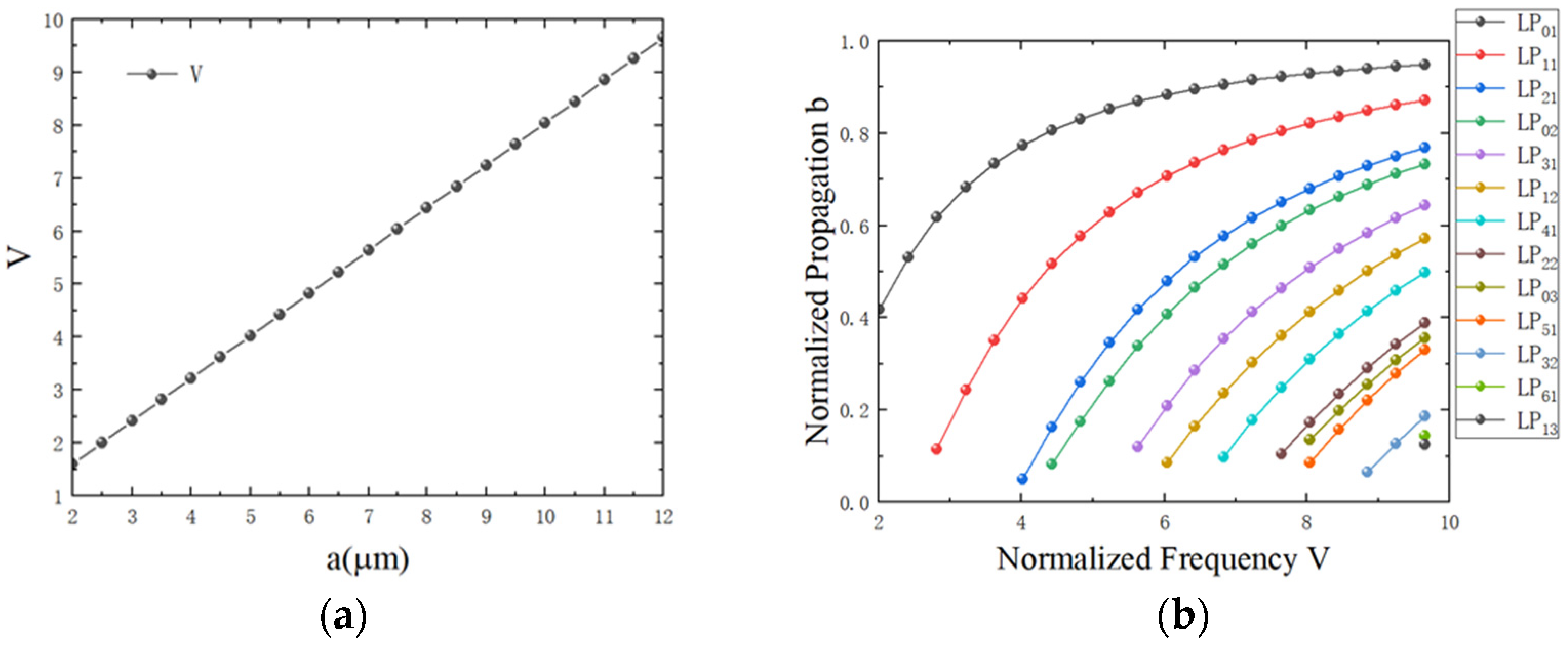
where λ is the wavelength and neff is the effective refractive of a vacuum. To elucidate the relationship between the core radius a and the normalized frequency V, the variation of b as a function of V is illustrated in Figure 1a. Furthermore, to maximize the supported LP mode count, the evolution of the modes in the SI-FMF is analyzed by adjusting V and the propagation constant b, with the results presented in Figure 1b. As illustrated in Figure 1a, the stability of the normalized frequency V improves as the core radius a increases. Furthermore, Figure 1b reveals that the LP61 and LP13 modes emerge only when the V value reaches a specific threshold of 9.653699, marking the transition point for these higher-order modes in the SI-FMF. A Δncore of less than 1% is specifically targeted to ensure fabrication feasibility. Exceeding this threshold significantly degrades manufacturing tolerance due to increased internal stress and potential preform cracking in standard MCVD/VAD processes. Within this 1% limit, our parametric scanning reveals that the selected values provide the optimal trade-off between mode capacity and modal separation.
Figure 1.
(a) The relationship between a and normalized frequency V. (b) Changing the normalized propagation constant b and the normalized frequency V changes the mode in the SI-FMF.
To enable the fiber to support modes LP61 and LP31, the core parameters are optimized with a Δncore of 0.94% and an rcore of 11.6 μm. It is observed that three specific sets of LP modes exhibit a highly degenerate propagation constant b, namely LP22 and LP03 modes, as well as LP03 and LP51 modes, and LP61 and LP31 modes. Increasing the Δneff between these nearly degenerate pairs—particularly the LP22 and LP03 modes, and the LP61 and LP31 modes—is crucial for minimizing IM-XT and enhancing the overall transmission performance. Generally, a larger numerical aperture is preferred in SI-FMFs to achieve a higher Δneff, thereby effectively suppressing IM-XT.
To quantitatively evaluate the nonlinear tolerance of the proposed structure for high-power transmission, the nonlinear coefficient γ is introduced and defined as the following:
where is the nonlinear refractive index of silicon dioxide (2.4 × 10⁻²⁰ m2/W) and is the effective mode area. As indicated by the equation, a larger effectively scales down the nonlinear coefficient, thereby suppressing Kerr-induced impairments such as self-phase modulation (SPM) and cross-phase modulation (XPM) in long-haul transmission systems.
In this work, the Δneff and the walk-off length are adopted to evaluate the influence of fiber bending on the eigenmodes within the ring regions. L2π and L10ps represent the propagation length when the x and y LP mode in the fiber have a 2π relative phase shift and a 10-ps temporal walk off. It is given by the following equations:
where , , and symbolize the wavelength, the vacuum velocity of light, and the temporal walk-off time, respectively. These parameters are fundamental in determining the modal characterization lengths, ensuring the scaling consistency between the phase-matching properties and the temporal walk-off limits.
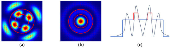
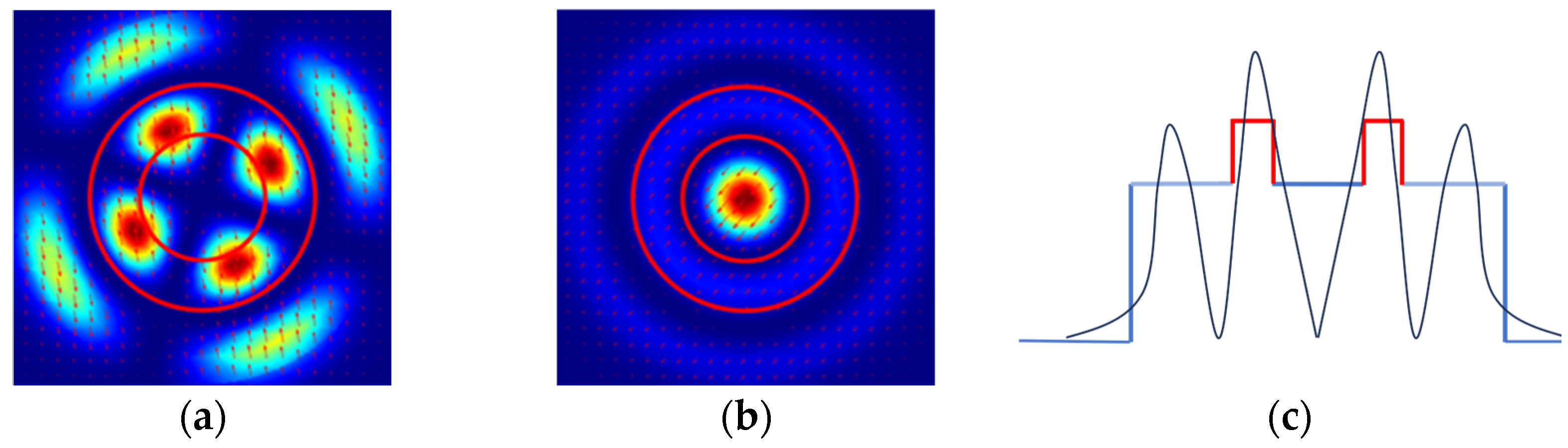
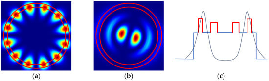
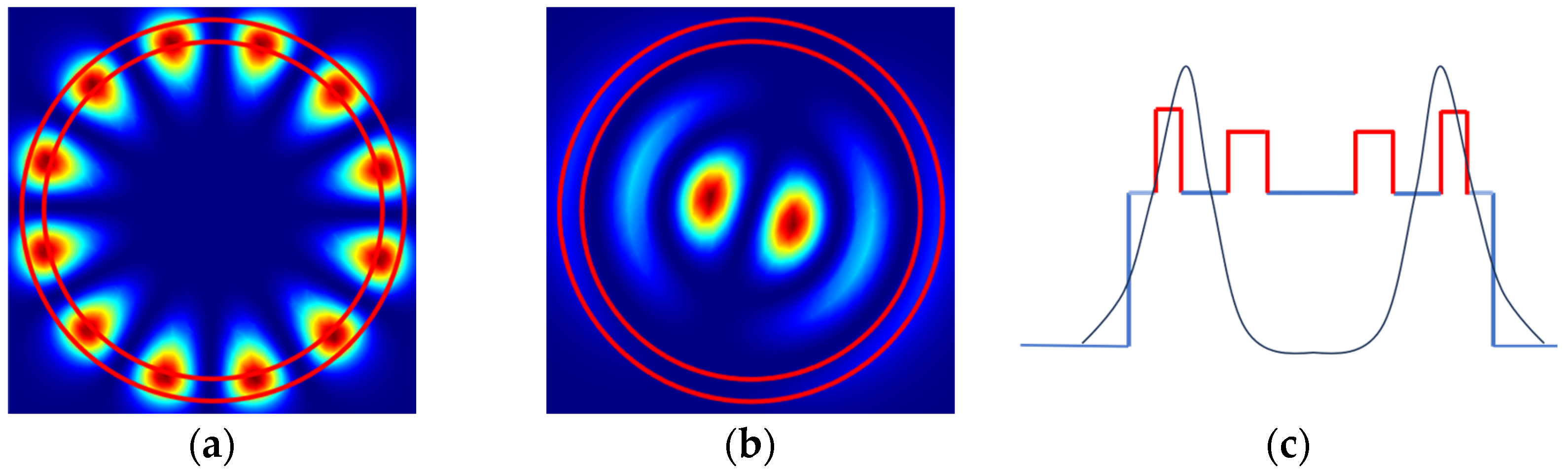
Integrating a ring-assisted (RA) structure into a step-index (SI) FMF provides an effective mechanism for redistributing the modal effective indices. By strategically overlapping the high-index RA region with specific modal fields, the phase constants of targeted modes can be selectively modulated. As illustrated in Figure 2a,b, the first RA structure exhibits a high spatial overlap with the LP22 mode but significantly less overlap with the LP03 mode. This selective overlap increases the neff of LP22 while leaving LP03 relatively unaffected, thereby widening their effective index difference. Specifically, the first ring is optimized to separate the LP22–LP03 pair, while the second ring is strategically positioned to enhance the separation between the LP61–LP13 pair. These two pairs are prioritized because their similar radial field distributions and closely matched neff in standard step–index fibers represent the primary limiting factors for Min|Δneff|. By fine-tuning the width, radial position, and refractive index profile of these rings, we can effectively redistribute the neff of specific high-order modes, ensuring that all 13 LP mode groups satisfy the Min|Δneff| > 1 × 10⁻⁴ criterion for low-crosstalk transmission.
Figure 2.
(a) Mode distribution of the LP22 mode; (b) mode distribution of the LP03 mode in RA-FMF; (c) overlap between the RA structure and the LP22 mode.
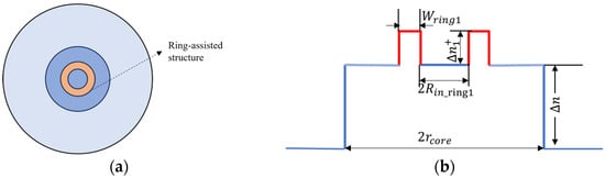
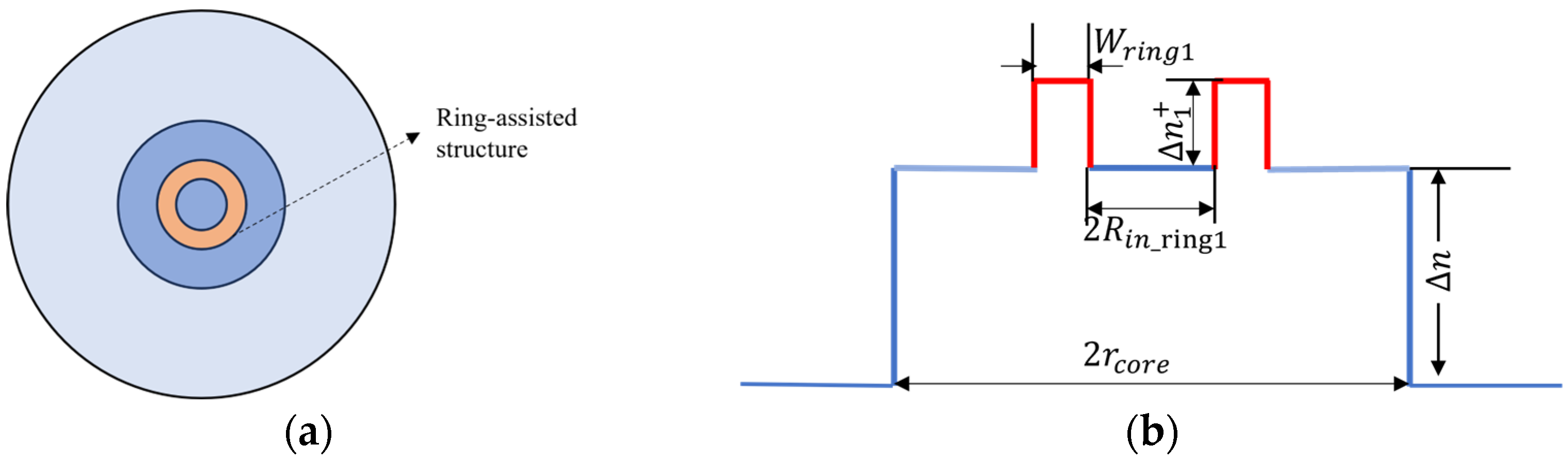
Initially, the SI fiber parameters (Δncore = 0.94%, rcore = 11.6 μm) that support the LP61 and LP31 modes are selected as the baseline model for this study. Subsequently, the finite element simulation implemented in COMSOL Multiphysics 6.1 is employed to numerically investigate how various structural parameters of the RA configuration influence the fiber’s modal characteristics. As shown in Figure 3a, the yellow ring is a high refractive index ring. In Figure 3b, Wring1 is the width of the high refractive index ring 1, is the refractive index difference between the high refractive index ring and the core layer, and Rin_ring1 is the radius of the inner circle of ring 1. We use = nring1 − ncore to express the difference between the refractive index of the high refractive index ring 1 and the refractive index of the core layer. The selection of the experimental initial values of , Rin_ring1, and Wring1 considered the feasibility of the preparation process and the mode operation of the RA 11-LP mode fiber.
Figure 3.
(a) Cross-sectional diagram of the RA 11-LP mode fiber. (b) Refractive index profile of the RA 11-LP mode fiber.
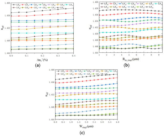
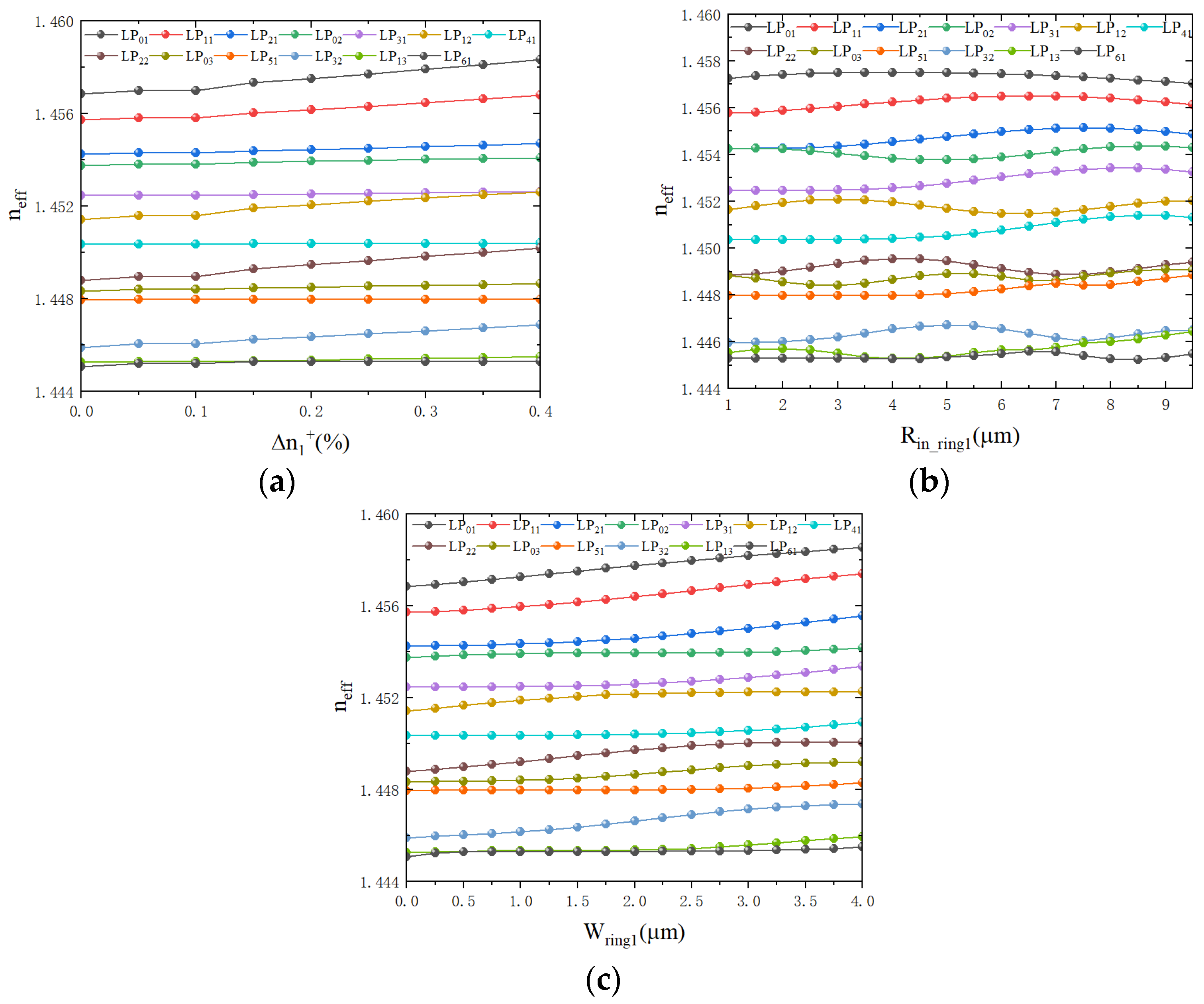
At the operating wavelength of 1550 nm, the dependence of neff on the structural parameters of the first RA structure (, Rin_ring1, and Wring1) is systematically analyzed in Figure 4. It is observed that in the foundational fiber profile, the Δneff between the LP13 and LP61 modes remains the primary bottleneck due to their closely matched phase constants, which necessitates the introduction of the second RA structure to achieve a robust 13-LP-mode-group fiber.
Figure 4.
The RA 11-LP mode fiber with Δncore = 0.94% and rcore = 11.6 μm as a function of (a) the first ring-core index difference Δn, with Wring1 = 1.5 μm and Rin_ring1 = 3.5 μm; (b) the radius of the inner circle of the ring 1 Rin_ring1, with Wring1 = 1.5 μm and = 0.2%; (c) the width of the high refractive index ring 1 Wring1, with Rin_ring1 = 3.5 μm and = 0.2%.
As illustrated in Figure 4a, with Wring1 and Rin_ring1 held constant, the Δneff between LP13 and LP61 increases monotonically with the doping concentration (). However, an excessive refractive index difference (exceeding 0.2%) induces a “mode compression” effect, where the for the LP31–LP12 and LP41–LP22 pairs begins to deteriorate. This trade-off suggests that the index perturbation must be carefully constrained to maintain global modal isolation. The radial position Rin_ring1 also plays a critical role in selective modal field enhancement. As shown in Figure 4b, deviations from the optimal range (3.5 μm to 4.5 μm) lead to an abrupt decline in Δneff for several adjacent mode pairs, as the ring structure shifts away from the high-field regions of the targeted modes. Similarly, Figure 4c indicates that while increasing the ring width Wring1 generally enhances modal separation, a range of 2.75 μm to 3.5 μm provides the most stable performance.
Because any structural modification induces localized perturbations that affect the entire eigenvalue spectrum of the fiber, a multi-parameter synergistic optimization strategy was employed. We focused on the simultaneous adjustment of (Rin_ring1, ) and (Rin_ring1, Wring1) to identify the global “sweet spot” that maximizes the Min|Δneff|. This approach ensures that even the most sensitive high-order modes, such as LP32 and LP13, maintain sufficient separation to suppress inter-mode power transfer.
3. Mode Characteristics of the RA 11-LP Mode Fiber
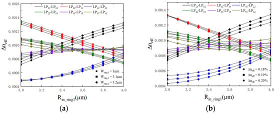
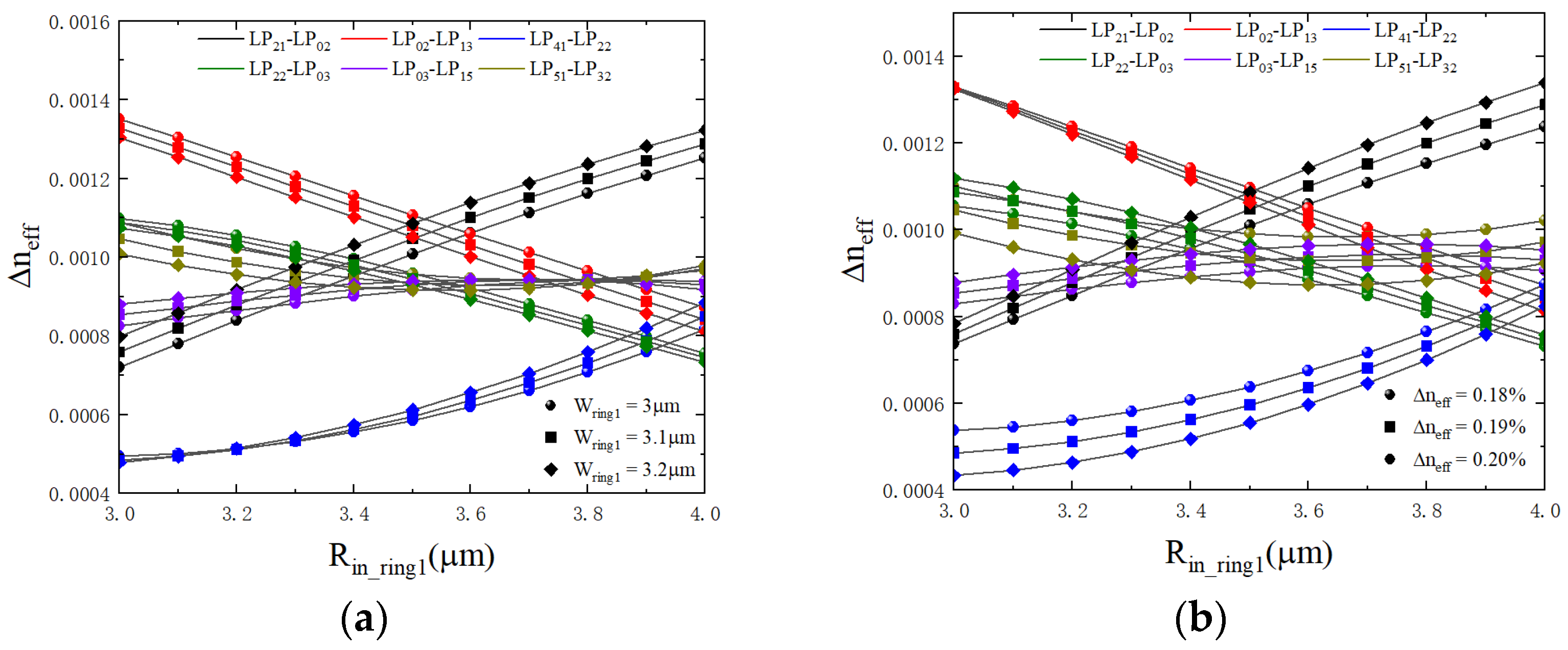
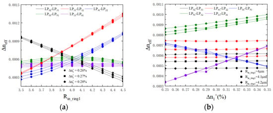
Based on the above analysis, we micro-adjusted the parameters of the RA structure to determine the range of parameters that can achieve the maximum Min|Δneff| around = 0.19% and Wring1 = 3.1 μm. Therefore, we use different symbols to represent different and Wring1 in Figure 5, and greatly change the value of Rin_ring1 to find the best RA structure. The Δneff of the six adjacent LP modes selected in Figure 5 is greatly affected by the RA structure and may become Min|Δneff|.
Figure 5.
When the RA 11–LP mode fiber is under the condition of Δncore = 0.94%, rcore = 11.6 μm, and Wring1 = 3.1 μm. (a) Δneff as a function of Rin_ring1 and ; (b) Δneff as a function of Rin_ring1 and Wring1.
To validate the design’s robustness, a quantitative sensitivity analysis was performed for the RA-FMF (Figure 5). Based on the bottleneck mode pair LP41–LP02, the following sensitivities were identified: a 0.1 μm increase in Rin_ring1 results in Δneff shifts of +0.01 × 10⁻³ and −0.04 × 10⁻³ for the LP41–LP22 and LP22–LP03 pairs, respectively. Similarly, a 0.1 μm enhancement in Wring1 leads to variations of +0.01 × 10⁻³ (LP41–LP22) and −0.001×10⁻³ (LP22–LP03). Furthermore, the impact of the is non-linear; each 0.01% increment induces Δneff shifts ranging from +0.01 × 10⁻³ to +0.05 × 10⁻³ for LP41–LP22 and −0.002 × 10⁻³ to −0.04 × 10⁻³ for LP22–LP03, with the sensitivity intensifying at higher baseline doping levels. It is worth highlighting that even under these parameter fluctuations, this specific mode pair remains the critical bottleneck, consistently exhibiting the minimum effective refractive index difference across the entire supported mode spectrum.
Therefore, the best structural parameters of RA 11-LP mode fiber are Rin_ring1 = 3.9 μm, = 0.19%, and Wring1 = 3.1 μm. The maximum Min|Δneff| = 0.78 × 10⁻³ can be achieved, which is the same as that of SI-FMF.
The main characteristics of the optimized RA 11-LP mode fiber at 1550 nm are listed in Table 1. The Min|Aeff| of the RA 11-LP mode fiber is 164 μm2, and more than 100 μm2 can effectively reduce the influence of optical nonlinearity. The calculated nonlinear coefficient of the proposed fiber is approximately 0.593 W−1 × km−1 at 1550 nm, which is significantly lower than that of conventional few-mode fibers (typically > 1.1 W−1 × km−1). This 46% reduction in nonlinearity is attributed to the large effective area. DGD vs. LP01 is the mode group delay relative to the LP01 mode, and the delay of the 11 LP mode groups supported by the fiber is not large. As the number of LP modes supported by the fiber increases, the dispersion will gradually increase; however, it is basically below 40 ps/(nm × km). Since the data is mainly obtained by simulation, the basic order of magnitude of the limiting loss is 10−12 dB/km, which is far less than 10−7 dB/km. Therefore, the simulation results can be considered up to standard.
Table 1.
Characteristics of the optimized RA 11-LP mode fiber at 1550 nm.
The high baseline Δneff of the optimized first ring acts as a robust barrier, as the index fluctuations induced by environmental perturbations (10−5) are several orders of magnitude smaller than the engineered modal gap [50]. Consequently, the design maintains stable mode separation and low crosstalk even under the mechanical stresses and thermal variations encountered in practical deployment [51]. Notably, the design exhibits significant robustness against fabrication tolerances. Specifically, given the substantial baseline Δneff of 0.78 × 10⁻³, the fiber maintains a nearly eight-fold safety margin above the critical threshold 10−4 required for stable mode isolation. This ensures that minor geometric variations in the core radius or ring thickness during manufacturing do not compromise the low-crosstalk performance.
4. Design, Characterization, and Comparative Analysis of the 13-LP Mode Fiber
4.1. Design of the CRA 13-LP Mode Fiber
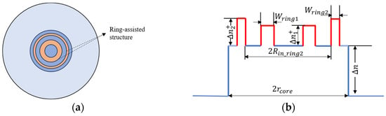
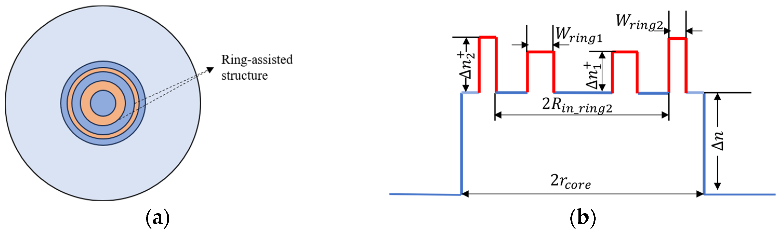
Based on the above method, we designed the second RA structure to separate the LP61 and LP13 modes. As illustrated in Figure 6a,b, the second RA structure is highly overlapped with the LP61 mode and weakly overlapped with the LP31 mode, which increases the Δneff between LP61 and LP13. The overlap between the second RA structure and the LP61 mode is shown in Figure 6c. Figure 7a shows the schematic diagram of the fiber with a concentric ring structure. In Figure 7b, Wring2 is the width of the high refractive index ring 2, is the refractive index difference between the high refractive index ring 2 and the core layer, and Rin_ring2 is the radius of the inner circle of ring 2. We use = nring2 − ncore to express the difference between the refractive index of the high refractive index ring 1 and the refractive index of the core layer. The two RA structures have the same center of the circle, which is called the CRA 13-LP mode fiber.
Figure 6.
(a) Mode distribution of the LP61 mode; (b) mode distribution of the LP31 mode in the CRA 13-LP mode fiber; (c) overlap between the RA structure and the LP61 mode.
Figure 7.
(a) Cross-sectional diagram of the CRA 13-LP mode fiber. (b) Refractive index profile of the CRA 13-LP mode fiber.
Notably, the structural dimensions of the second RA ring are strictly constrained by the radial distributions of the targeted high-order modes. The inner and outer radii are optimized at 9.9 μm and 11.2 μm, respectively, to ensure precise modal control. If the inner boundary is less than 9.9 μm, the RA structure incurs an unintended spatial overlap with the LP51 mode, which excessively elevates its neff and consequently reduces the Δneff between the LP51 and LP03 pair. Conversely, if the outer boundary fails to reach 11.2 μm, the LP61 mode—which exhibits a more extended radial field—will experience insufficient overlap with the high-index region. This results in a negligible shift in its neff, rendering the RA structure ineffective for separating the LP61–LP13 mode pair. Therefore, this specific radial window serves as a spatial filter that selectively modulates the phase constants of target modes while preserving the isolation of adjacent mode groups.
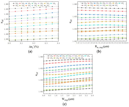
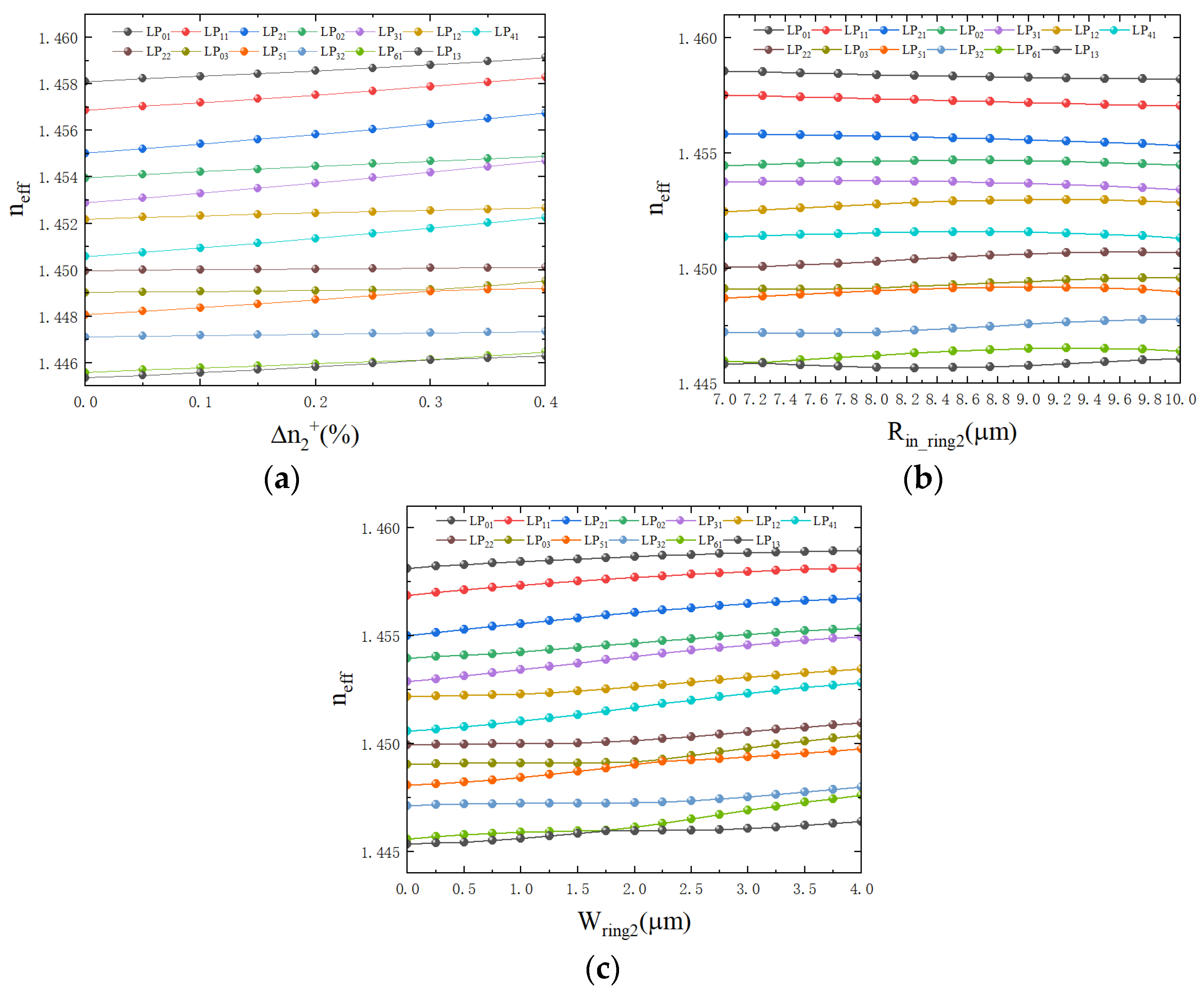
Based on the previous parameters of the first RA structure, the second RA structure parameter scan is performed. Since the outer boundary of the first RA structure is 6.6 μm, Rin_ring2 chooses to start from 7 μm. Under the condition of light with a wavelength of 1550 nm, the function of neff with , Rin_ring2, and Wring2 is shown in Figure 8a–c. By observing Figure 8a, it is found that with an increase in , the Δneff between LP61 and LP31 modes does not increase significantly and remains almost unchanged. As illustrated in Figure 8b, it is found that when Rin_ring2 is greater than 7.5 μm, the Δneff of LP61 and LP31 modes gradually increases, and when it exceeds 9.25 μm, it gradually decreases. In this interval, the Δneff of the LP03 and LP51 modes is too small, and the effect is not ideal. As illustrated in Figure 8c, with an increase in Wring2, and when Wring2 is greater than 2.25 μm, the Δneff of LP61 and LP31 modes gradually increases. However, the Δneff of LP32 and LP61 gradually decreases, which means that the best result is not in this range. Therefore, the radial position of the first RA structure must be adjusted, while the second ring should be strategically spaced from the first to minimize cross-modal interference.
Figure 8.
CRA 13-LP mode fiber with Δncore = 0.94%, rcore = 11.6 μm, Rin_ring1 = 3.9 μm, = 0.19%, and Wring1 = 3.1 μm as a function of (a) the second ring-core index difference with Wring2 = 1.5 μm and Rin_ring2 = 7 μm; (b) the radius of the inner circle of the ring 2 Rin_ring2 with Wring2 = 1.5 μm and = 0.2%; (c) the width of the high refractive index ring 2 Wring2 with Rin_ring2 = 7 μm and = 0.2%.
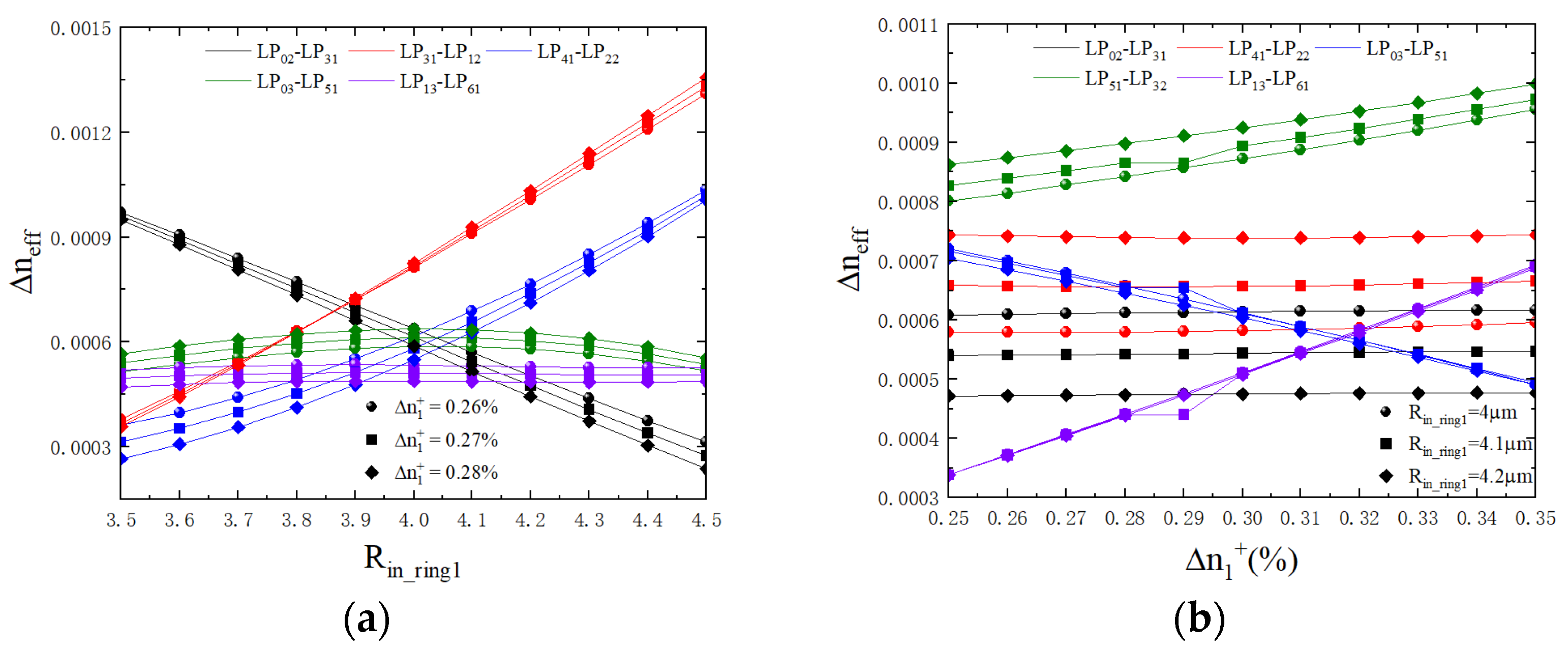
To pinpoint the optimal design, a systematic evaluation was conducted. As shown in Figure 9a, within the identified optimal regime, the Δneff of LP31–LP12 and LP41–LP22 improves with Rin_ring1, while LP02–LP31 exhibits the opposite trend. Building upon this, a fine-grained optimization was performed by coupling and Rin_ring1 (Figure 9b) to maximize the global Min|Δneff|. Based on this baseline, a quantitative sensitivity analysis was performed for the CRA-FMF. For the first RA structure, a 0.1 μm increase in Rin_ring1 results in Δneff variations of +0.005 × 10⁻³, +0.04 × 10⁻³, and −0.07 × 10⁻³ for the LP31–LP61, LP41–LP22, and LP02–LP21 pairs, respectively. Similarly, each 0.01% increment in leads to shifts of −0.05 × 10⁻³ (LP41–LP22), −0.01 × 10⁻³ (LP02–LP21), and −0.025 × 10⁻³ (LP31–LP61). Crucially, this mode pair remains the limiting bottleneck with the Min|Δneff| across the analyzed range. Optimal parameters for the first ring of the CRA structure were identified as follows: Rin_ring1 = 4.1 μm, Wring1 = 3.1 μm, and = 0.27%.
Figure 9.
When CRA 13-LP mode fiber is under the condition of Δncore = 0.94%, rcore = 11.6 μm, Wring1 = 3.1 μm, Rin_ring2 = 9.9 μm, Wring2 = 1.3 μm, and = 0.3%. (a) Δneff as a function of the coarse-stepped Rin_ring1 and the fine-stepped ; (b) Δneff as a function of the fine-stepped Rin_ring1 and the coarse-stepped .
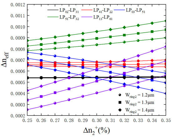
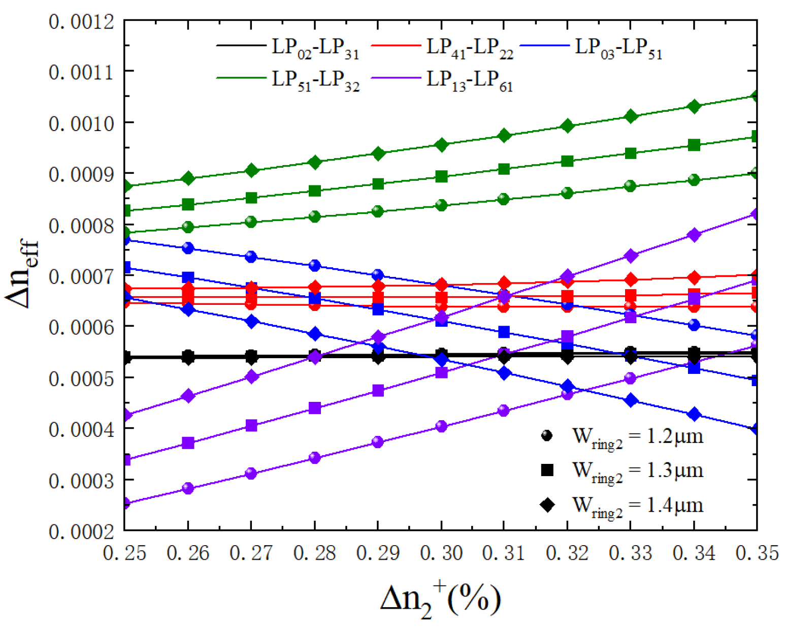
The simulation of Rin_ring2 and of the second RA structure is carried out on the identified first RA structure. The outer ring of the second RA structure is fixed at 11.2 μm, and the and Wring2 are changed as shown in Figure 10. With an increase in and the Δneff of the LP51 and LP32 modes, the LP13 and LP61 modes increase, the Δneff of the LP03 and LP51 modes decrease, and the Δneff of the other two groups is almost unchanged. Therefore, the best parameter of the second RA structure is = 0.32% and Wring2 = 1.3 μm. To validate the robustness of this design, a quantitative sensitivity analysis was performed around this optimal point. A 0.1 μm increase in Wring2 results in Δneff shifts of +0.013 × 10⁻³ and −0.0015 × 10⁻³ for the LP31–LP61 and LP02–LP21 pairs, respectively. Furthermore, for every 0.01% increment in , the Δneff for LP02–LP21 and LP31–LP61 varies by +0.001 × 10⁻³ and +0.03 × 10⁻³. In all cases, this mode pair persists as the critical bottleneck, consistently exhibiting the lowest Δneff across the investigated parameter range.
Figure 10.
When the CRA 13-LP mode fiber is under the condition of Δncore = 0.94%, rcore = 11.6 μm, Rin_ring1 =4.1 μm, Wring1 = 3.1 μm, and = 0.27%. Δneff as a function of and Wring2.
4.2. Mode Characteristics of the CRA 13-Mode Fiber
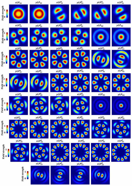
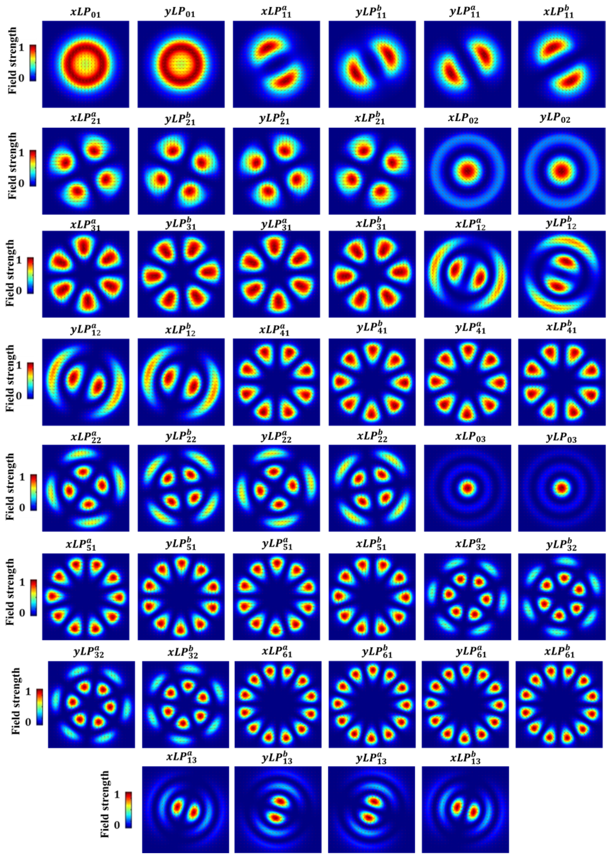
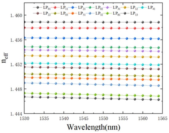
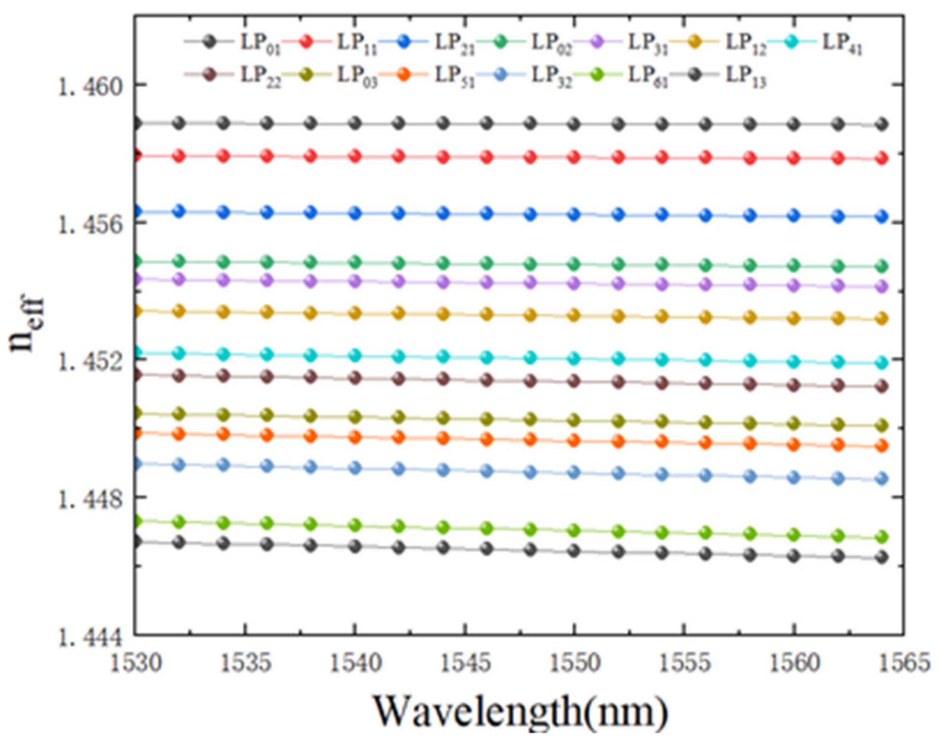
Figure 11 is a schematic diagram of all the modes supported by the CRA 13-LP mode fiber at a wavelength of 1550 nm. The LP0n mode is two-fold degenerate, whereas the other LP modes are quadruple degenerate. In Figure 11, x and y of the LP mode represent the polarization direction, and a and b represent two mutually orthogonal modes. We also measured the neff of the CRA 13-LP mode fiber at different wavelengths. As illustrated in Figure 12, the neff of all supported modes remains remarkably stable across the entire C band. The negligible fluctuations in neff with respect to wavelength variations demonstrate that the modal characteristics are highly insensitive to wavelength changes, ensuring consistent performance over a broad operating range.
Figure 11.
A schematic diagram of all the modes supported by the CRA 13-LP mode fiber at a wavelength of 1550 nm.
Figure 12.
Effective refractive index of all the LP modes of the CRA 13-LP mode fiber within the C band.
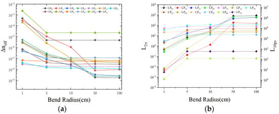
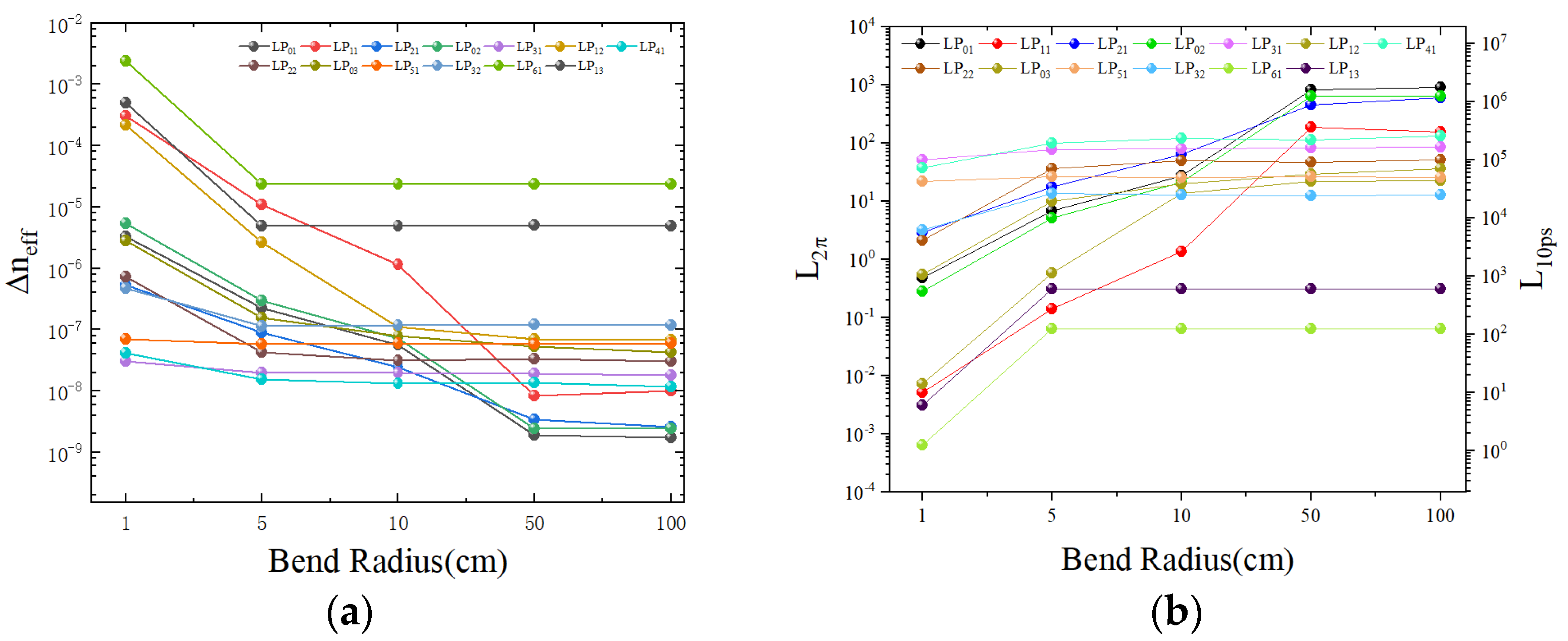
Figure 13a,b illustrate the Δneff, L2π, and L10ps under varying bending radii at = 1550 nm. For lower-order modes such as LP01 and LP21, the Δneff exhibits significant variations from 10−6 to 10−9 as the bending radius increases from 1 cm to 100 cm. In contrast, higher-order modes like LP61 and LP13 show a larger variation in range, with Δneff spanning from 10−3 to 10−6. At a tight bending radius of approximately 1 cm, the L2π and L10ps for higher-order modes are markedly reduced, but they significantly improve and stabilize once the radius exceeds 5 cm. Most modes reach a steady state beyond a 10 cm radius, with negligible changes in L2π and L10ps between 50 cm and 100 cm. For bending radii above 5 cm, the L10ps of higher-order modes reaches several hundred meters, while lower-order modes can achieve 105 m to 106 m, with the LP01 mode even reaching 107 m. Crucially, the identified bottleneck mode pair consistently maintains the Min|Δneff| throughout the bending analysis, effectively suppressing inter-mode crosstalk under realistic physical perturbations. This high modal isolation allows for modular, small-scale MIMO equalization within mode groups instead of high-complexity global MIMO, significantly reducing computational overhead. Consequently, the proposed CRA-FMF is well-suited for stable short-to-medium haul transmissions (e.g., data center interconnects) where low-complexity signal processing and robust crosstalk suppression are prioritized.
Figure 13.
(a) Effective refractive index differences; (b) L2π and L10ps versus bend radius for the CRA 13–LP mode fiber.
The primary optical characteristics of the optimized CRA 13-LP mode fiber at 1550 nm is summarized in Table 2. Compared to the RA 11-LP mode group fiber, the Min|Aeff| of the CRA fiber slightly decreases to 131 μm2; however, it remains well above 100 μm2. Following the theoretical framework in Equation (5), the nonlinear coefficient for the CRA structure is calculated to be 0.74 W−1 × km−1 at 1550 nm. This low value is particularly crucial for CRA fibers as it minimizes the nonlinear phase noise that could otherwise lead to the crosstalk between degenerate OAM modes, thereby ensuring the purity and stability of mode division multiplexing over long distances, and effectively mitigating nonlinear impairments. The Min|Δneff| is maintained at 0.55 × 10⁻³, providing sufficient suppression of inter-modal crosstalk (IM-XT) despite the increased mode density. Although the differential group delay (DGD) naturally scales with the number of supported modes, it is strictly confined within 42 ps/m. Furthermore, the chromatic dispersion is capped at 45 ps/(nm × km). Notably, the confinement loss is approximately 10−12 dB/km, ensuring excellent signal confinement, although actual attenuation would be dominated by material scattering and absorption (typically 0.2 dB/km). Similarly, the CRA-FMF maintains a robust Min|Δneff| of 0.55 × 10⁻³, providing a nearly six-fold safety margin above the 10−4 threshold. This ensures stable mode isolation and high fabrication tolerance even with the increased mode density, effectively suppressing inter-mode crosstalk during practical manufacturing.
Table 2.
Characteristics of the optimized CRA 13-LP mode fiber at 1550 nm.
4.3. Performance Comparison and Discussion
Table 3 presents a quantitative comparison between our designs and previously reported few-mode fibers. While the RA-FMF supports 11 LP mode groups with a Min|Δneff| of 0.78 × 10⁻³, the optimized CRA-FMF expands the capacity to 13 LP mode groups (46 modes). Despite the increased mode density, the CRA-FMF maintains 0.78 × 10⁻³ of 0.55 × 10⁻³, effectively suppressing inter-mode power transfer and crosstalk to enable low-complexity MIMO equalization. Furthermore, the CRA-FMF achieves a Min|Aeff| of 131μm2, which is vital for mitigating nonlinear effects in long-haul transmission. Compared to the four LP mode design in [48] with a DMD of 13.45 ns/km, our CRA-FMF provides a 3.8-fold capacity increase while maintaining a manageable DMD of 44.2 ns/km. These results confirm that the graded concave profile superiorly balances high spatial efficiency, robust coupling suppression, and nonlinear tolerance.
Table 3.
Performance comparison of various weakly coupled fiber designs in terms of mode capacity and index difference.
Furthermore, the proposed CRA-FMF offers significant advantages for practical system integration and selective mode excitation in MDM networks. The fiber’s large Min|Δneff| of 0.55 × 10⁻³ ensures strong suppression of inter-modal crosstalk, providing high modal stability during long-haul transmission. In a typical communication link, independent data streams from a single-mode fiber (SMF) array can be converted and coupled into the specific supported modes of the CRA-FMF using multiplexing devices such as photonic lanterns, mode-selective couplers (MSCs), or free-space mode sorters. The performance of these excitation devices is highly dependent on phase-matching conditions. Our design’s superior Δneff ensures a sharp phase-matching response, which effectively suppresses unwanted coupling to adjacent modes and enhances mode purity. At the receiver end, the spatial channels are demultiplexed and recovered using low-complexity MIMO processing. Combined with its manageable DMD and large Min|Aeff|, the CRA-FMF demonstrates strong potential for seamless integration into existing weakly coupled MDM systems.
5. Conclusions
We have proposed and numerically demonstrated an RA fiber supporting 11 LP mode groups and a CRA fiber supporting 13 LP mode groups. By introducing a high refractive index ring to overlap with the LP22 mode, the effective refractive index of the LP22 mode is largely improved. We have successfully designed the RA 11-LP mode fiber with Min|Δneff| = 0.78 × 10⁻³, which is almost the same as the SI-4 mode fiber. On this basis, we designed the CRA 13-LP mode fiber in the same way. Based on the existing first RA structure, a second concentric RA structure was added. The second RA structure enhances the effective refractive index of LP61 by overlapping with the LP61 mode. Furthermore, Min|Δneff| = 0.55 × 10⁻³ and Min|Aeff| = 131 μm2 for the CRA 13-LP mode fiber, and the effective refractive index is stable for all LP modes within the C band. Through multiple RA structures, it is expected to achieve a CRA fiber that can support more LP modes and improve the transmission capacity of the fiber.
Regarding the practical feasibility, the CRA fiber can be precisely realized using modern MCVD or PCVD techniques, where dopant flow rates are finely tuned to achieve the required 10−4 refractive index resolution. The scalability of this multi-ring geometry allows for flexible adaptation to higher-order OAM mode transmission or large-mode-area applications by proportionally adjusting the radial dimensions. Future work will focus on experimental verification, including preform fabrication and characterization of transmission loss and modal crosstalk, to further validate its application prospects in high-capacity optical communications and advanced sensing.
Author Contributions
Conceptualization, Y.L. and C.Z.; methodology, Y.L., S.M. and C.Z.; software, C.Z. and X.Z.; validation, C.Z.; formal analysis, Y.L., X.Z. and C.Z.; investigation, C.Z.; data curation, C.Z.; writing—original draft preparation, C.Z.; writing—review and editing, H.X., J.Z., Y.L. and S.M.; visualization, H.X., J.Z. and C.Z.; supervision, Y.L. and S.M.; project administration, Y.L. and S.M.; funding acquisition, X.Z. and Y.L. All authors have read and agreed to the published version of the manuscript.
Funding
This work was supported by the National Natural Science Foundation of China (62405233), the Opening Project of Modern Precision Measurement and Laser Non-destructive Testing Key La-boratory of Higher Education in Fujian Province (Putian University, Grants No. XKA202505), and the Jiangsu Funding Program for Excellent Postdoctoral Talent (2025ZB101).
Data Availability Statement
All data, theory details, and simulation details that support the findings of this study are available from the corresponding authors upon reasonable request.
Conflicts of Interest
Author Xi Zhang was employed by the company Jiangsu Alpha Optic-Electric Technology Co., Ltd. Author Haixuan Xu was employed by the company China Mobile Information Technology Co., Ltd. The remaining authors declare that the research was conducted in the absence of any commercial or financial relationships that could be construed as a potential conflict of interest.
References
- Essiambre, R.; Kramer, G.; Winzer, P.J.; Foschini, G.J.; Goebel, B. Capacity limits of optical fiber networks. J. Light. Technol. 2010, 28, 662–701. [Google Scholar] [CrossRef] [Scilit]
- Liang, Y.; Wang, H.; Liu, J.; Wang, J. Experimental demonstration of visualized multi-core fiber coupling alignment system for inter-core cross talk measurement. Opt. Lett. 2022, 47, 3071–3074. [Google Scholar] [CrossRef] [Scilit]
- Wang, Y.; Yang, C.; Wang, Y.; Chi, N. Gigabit polarization division multiplexing in visible light communication. Opt. Lett. 2014, 39, 1823–1826. [Google Scholar] [CrossRef] [Scilit]
- Dong, P. Silicon photonic integrated circuits for wavelength-division multiplexing applications. IEEE J. Sel. Top. Quant. 2016, 22, 370–378. [Google Scholar] [CrossRef] [Scilit]
- Hamilton, S.A.; Robinson, B.S.; Murphy, T.E.; Savage, S.J.; Ippen, E.P. 100 Gb/s Optical Time-Division Multiplexed Networks. J. Light. Technol 2002, 20, 2086. [Google Scholar] [CrossRef]
- Richardson, D.J.; Fini, J.M.; Nelson, L.E. Space-division multiplexing in optical fibres. Nat. Photonics 2013, 7, 354–362. [Google Scholar] [CrossRef] [Scilit]
- Ma, Z.; Ramachandran, S. Propagation stability in optical fibers: Role of path memory and angular momentum. Nanophotonics 2021, 10, 209–224. [Google Scholar] [CrossRef] [Scilit]
- Liang, Y.; Cao, S.; Liu, L.; Liu, F.; Yin, X.; Lv, P.; Zhang, Y.; Zou, Y.; Fang, L.; Zheng, S.; et al. Coherent detector for the non-separability measurement of vectorial structured light. Light Sci. Appl. 2025, 14, 343. [Google Scholar] [CrossRef] [Scilit]
- Ingerslev, K.; Gregg, P.; Galili, M.; Da Ros, F.; Hu, H.; Bao, F.; Castaneda, M.A.U.; Kristensen, P.; Rubano, A.; Marrucci, L.; et al. 12 mode, WDM, MIMO-free orbital angular momentum transmission. Opt. Express 2018, 26, 20225–20232. [Google Scholar] [CrossRef] [Scilit]
- Li, G.; Bai, N.; Zhao, N.; Xia, C. Space-division multiplexing: The next frontier in optical communication. Adv. Opt. Photonics 2014, 6, 413–487. [Google Scholar] [CrossRef] [Scilit]
- Puttnam, B.J.; Rademacher, G.; Luís, R.S. Space-division multiplexing for optical fiber communications. Optica 2021, 8, 1186–1203. [Google Scholar] [CrossRef] [Scilit]
- Lu, K.; Chen, Z.; Chen, H.; Zhou, W.; Zhang, Z.; Tsang, H.K.; Tong, Y. Empowering high-dimensional optical fiber communications with integrated photonic processors. Nat. Commun. 2024, 15, 3515. [Google Scholar] [CrossRef] [Scilit] [PubMed]
- Ma, Z.; Kristensen, P.; Ramachandran, S. Scaling information pathways in optical fibers by topological confinement. Science 2023, 380, 278–282. [Google Scholar] [CrossRef] [Scilit] [PubMed]
- Bozinovic, N.; Yue, Y.; Ren, Y.; Tur, M.; Kristensen, P.; Huang, H.; Willner, A.E.; Ramachandran, S. Terabit-Scale Orbital Angular Momentum Mode Division Multiplexing in Fibers. Science 2013, 340, 1545–1548. [Google Scholar] [CrossRef] [Scilit]
- Wang, J. Advances in communications using optical vortices. Photonics Res. 2016, 4, B14–B28. [Google Scholar] [CrossRef] [Scilit]
- Liang, Y.; Wang, H.; Zhang, X.; Ai, J.; Ma, Z.; Ramachandran, S.; Wang, J. Reconfigurable structured light generation and its coupling to air–core fiber. Adv. Photonics Nexus 2023, 2, 36015. [Google Scholar] [CrossRef] [Scilit]
- Wang, F.; Gao, R.; Li, Z.; Liu, J.; Cui, Y.; Xu, Q.; Pan, X.; Zhu, L.; Wang, F.; Guo, D.; et al. OAM mode-division multiplexing IM/DD transmission at 4.32|Tbit/s with a low-complexity adaptive-network-based fuzzy inference system nonlinear equalizer. Opt. Lett. 2024, 49, 430–433. [Google Scholar] [CrossRef] [Scilit]
- Liang, Y.; Xi, T.; Cao, S.; Liu, L.; Liu, F.; Wan, Z.; Wang, J.; Shao, X. Spatiotemporal vectorial structured light that dynamically varies on higher-order Poincaré sphere. Opt. Express. 2024, 32, 28413–28428. [Google Scholar] [CrossRef] [Scilit]
- Cao, S.; Ruan, Z.; Ren, W.; Qin, S.; Yin, X.; Liu, L.; Liang, Y.; Xu, H. Tailoring Perfect Optical Vortex Combs Based on Diffractive Neural Networks. Laser Photonics Rev. 2025, 20, e2383. [Google Scholar] [CrossRef] [Scilit]
- Mojaver, K.R.; Safaee, S.M.R.; Morrison, S.S.; Liboiron-Ladouceur, O. Recent Advancements in Mode Division Multiplexing for Communication and Computation in Silicon Photonics. J. Light. Technol. 2024, 42, 7860–7870. [Google Scholar] [CrossRef] [Scilit]
- Liang, Y.; Hu, X.; Wang, Q.; Wang, J. Tailoring optical vortex beams based on diffractive neural networks for high-quality ring-core fiber coupling. Opt. Lett. 2025, 50, 3788–3791. [Google Scholar] [CrossRef] [Scilit]
- Gregg, P.; Kristensen, P.; Ramachandran, S. Conservation of orbital angular momentum in air-core optical fibers. Optica 2015, 2, 267–270. [Google Scholar] [CrossRef] [Scilit]
- Bushuev, D.; Arnon, S. Analysis of the performance of a wireless optical multi-input to multi-output communication system. J. Opt. Soc. Am. 2006, 23, 1722–1730. [Google Scholar] [CrossRef] [Scilit] [PubMed]
- Willner, A.E.; Song, H.; Zou, K.; Zhou, H.; Su, X. Orbital angular momentum beams for high-capacity communications. J. Light. Technol. 2022, 41, 1918–1933. [Google Scholar] [CrossRef] [Scilit]
- Liu, J.; Zhang, J.; Liu, J.; Lin, Z.; Li, Z.; Lin, Z.; Zhang, J.; Huang, C.; Mo, S.; Shen, L. 1-Pbps orbital angular momentum fibre-optic transmission. Light Sci. Appl. 2022, 11, 202. [Google Scholar]
- Yue, Y.; Yan, Y.; Ahmed, N.; Yang, J.; Zhang, L.; Ren, Y.; Huang, H.; Birnbaum, K.M.; Erkmen, B.I.; Dolinar, S. Mode properties and propagation effects of optical orbital angular momentum (OAM) modes in a ring fiber. IEEE Photonics J. 2012, 4, 535–543. [Google Scholar]
- Sillard, P.; Bigot-Astruc, M.; Molin, D. Few-mode fibers for mode-division-multiplexed systems. J. Light. Technol. 2014, 32, 2824–2829. [Google Scholar] [CrossRef] [Scilit]
- Wang, J.; Zhang, X. Orbital angular momentum in fibers. J. Light. Technol. 2022, 41, 1934–1962. [Google Scholar] [CrossRef] [Scilit]
- Geng, W.; Fang, Y.; Bao, C.; Pan, Z.; Yue, Y. Emission of five OAM dispersive waves in dispersion-engineered double-ring core fiber. Sci. Rep. 2024, 14, 8474. [Google Scholar] [CrossRef] [Scilit]
- Zhao, W.; Wang, Y.; Ren, H.; Geng, W.; Liu, Y.; Pan, Z.; Yue, Y. Recent advances in ring-core fiber for orbital-angular-momentum-based mode-division multiplexing. Opt. Commun. 2025, 591, 132091. [Google Scholar] [CrossRef] [Scilit]
- Wang, G.; Zhang, J.; Zhang, H.; Wang, F.; Yan, X.; Zhang, X.; Li, S.; Cheng, T. A low crosstalk multi-core few-mode fiber with composite refractive index profile and air-hole embedded trench assistance. Opt. Commun. 2021, 499, 127258. [Google Scholar]
- Zhang, J.; Zhu, J.; Liu, J.; Mo, S.; Zhang, J.; Lin, Z.; Shen, L.; Zhang, L.; Luo, J.; Liu, J. Accurate mode-coupling characterization of low-crosstalk ring-core fibers using integral calculation based swept-wavelength interferometry measurement. J. Light. Technol. 2021, 39, 6479–6486. [Google Scholar]
- Zhang, X.; Wang, J. Design of Multilayered Ring-Core Fiber With Low-Level Inter-Group Crosstalk. IEEE J. Quantum Elect. 2023, 59, 6800208. [Google Scholar] [CrossRef] [Scilit]
- Sillard, P.; Bigot-Astruc, M.; Boivin, D.; Maerten, H.; Provost, L. Few-Mode Fiber for Uncoupled Mode-Division Multiplexing Transmissions. In 37th European Conference and Exposition on Optical Communications; Optica Publishing Group: Geneva, Switzerland, 2011. [Google Scholar]
- Ma, L.; Jiang, S.; Du, J.; Yang, C.; Tong, W.; He, Z. Ring-Assisted 7-LP-Mode Fiber with Ultra-Low Inter-Mode Crosstalk. In Proceedings of the 2016 Asia Communications and Photonics Conference (ACP), Wuhan, China, 2–5 November 2016. [Google Scholar]
- Zhu, G.; Hu, Z.; Wu, X.; Du, C.; Luo, W.; Chen, Y.; Cai, X.; Liu, J.; Zhu, J.; Yu, S. Scalable mode division multiplexed transmission over a 10-km ring-core fiber using high-order orbital angular momentum modes. Opt. Express 2018, 26, 594–604. [Google Scholar] [CrossRef] [Scilit]
- Zhu, L.; Zhu, G.; Wang, A.; Wang, L.; Ai, J.; Chen, S.; Du, C.; Liu, J.; Yu, S.; Wang, J. 18 km low-crosstalk OAM + WDM transmission with 224 individual channels enabled by a ring-core fiber with large high-order mode group separation. Opt. Lett. 2018, 43, 1890–1893. [Google Scholar] [CrossRef] [Scilit] [PubMed]
- Ramachandran, S.; Gregg, P.; Kristensen, P.; Golowich, S.E. On the scalability of ring fiber designs for OAM multiplexing. Opt. Express 2015, 23, 3721–3730. [Google Scholar] [CrossRef] [Scilit] [PubMed]
- Demas, J.; Hary, M.; Genty, G.; Ramachandran, S. Optimization and realignment of OAM mode excitation in ring-core optical fibers using machine learning. Opt. Lett. 2024, 49, 5003–5006. [Google Scholar] [CrossRef] [Scilit]
- Gulistan, A.; Ghosh, S.; Ramachandran, S.; Rahman, B.M.A. Efficient strategy to increase higher order inter-modal stability of a step index multimode fiber. Opt. Express 2017, 25, 29714–29723. [Google Scholar] [CrossRef] [Scilit]
- Gulistan, A.; Ghosh, S.; Rahman, B. Enhancement of modal stability through reduced mode coupling in a few-mode fiber for mode division multiplexing. OSA Continuum 2018, 1, 309–319. [Google Scholar] [CrossRef] [Scilit]
- Jiang, S.; Ma, L.; Zhang, Z.; Xu, X.; Wang, S.; Du, J.; Yang, C.; Tong, W.; He, Z. Design and characterization of ring-assisted few-mode fibers for weakly coupled mode-division multiplexing transmission. J. Light. Technol. 2018, 36, 5547–5555. [Google Scholar]
- He, Z.; Du, J.; Chen, X.; Shen, W.; Huang, Y.; Wang, C.; Xu, K.; He, Z. Machine learning aided inverse design for few-mode fiber weak-coupling optimization. Opt. Express 2020, 28, 21668–21681. [Google Scholar] [CrossRef] [Scilit] [PubMed]
- Jin, X.; Gomez, A.; Shi, K.; Thomsen, B.C.; Feng, F.; Gordon, G.S.D.; Wilkinson, T.D.; Jung, Y.; Kang, Q.; Barua, P.; et al. Mode Coupling Effects in Ring-Core Fibers for Space-Division Multiplexing Systems. J. Light. Technol. 2016, 34, 3365–3372. [Google Scholar] [CrossRef] [Scilit]
- Simović, A.; Djordjevich, A.; Savović, S. Influence of depth of intermediate layer on optical power distribution in W-type optical fibers. Appl. Opt. 2012, 51, 4896–4901. [Google Scholar] [CrossRef] [Scilit] [PubMed]
- Brunet, C.; Ung, B.; Wang, L.; Messaddeq, Y.; LaRochelle, S.; Rusch, L.A. Design of a family of ring-core fibers for OAM transmission studies. Opt. Express 2015, 23, 10553–10563. [Google Scholar] [CrossRef] [Scilit]
- Simović, A.; Drljača, B.; Savović, S.; Djordjevich, A.; Min, R. Investigation of bandwidth in multimode graded-index plastic optical fibers. Opt. Express 2021, 29, 29587–29594. [Google Scholar] [CrossRef] [Scilit]
- Zhang, X.; Chen, S.; Wang, J. Weakly guiding graded-index ring-core fiber supporting 16-channel long distance mode division multiplexing systems based on OAM modes with low MIMO-DSP complexity. Opt. Express 2022, 30, 35828–35839. [Google Scholar] [CrossRef] [Scilit]
- Song, Y.; Zheng, J.; Pei, L.; Huang, J.; Wang, J.; Ning, T.; Li, J.; Bai, B. Design and characteristics of ellipse-assisted ring-core fiber for space division multiplexing. Opt. Fiber Technol. 2022, 72, 102984. [Google Scholar] [CrossRef] [Scilit]
- Yan, Z.; Sun, Q.; Wang, C.; Sun, Z.; Mou, C.; Zhou, K.; Liu, D.; Zhang, L. Refractive index and temperature sensitivity characterization of excessively tilted fiber grating. Opt. Express 2017, 25, 3336–3346. [Google Scholar] [CrossRef] [Scilit]
- Liang, J.; Qiao, G.; Wei, J.; Li, J.; Yang, Y.; Xu, Z.; Liu, L.; Wang, S.; Wu, Q.; Hu, W. Micro-Bending Influence on Mode-Dependent Loss. In Proceedings of the 2023 IEEE 15th International Conference on Advanced Infocomm Technology (ICAIT), Hefei, China, 13–16 October 2023; pp. 203–206. [Google Scholar]
- Lu, G.; Liu, S.; Lv, D.; Chen, M.; Zhang, Z. Design of ring-assisted few-mode fiber with low loss for improved mode-division multiplexing. Laser Phys. 2021, 31, 105101. [Google Scholar] [CrossRef] [Scilit]
- Zhang, J.; Wang, G.; Zhang, H.; Wang, F.; Yan, X.; Zhang, X.; Li, S.; Cheng, T. A Weakly-Coupled Few-Mode Optical Fiber With a Graded Concave High-Index-Ring. IEEE Photonics J. 2021, 13, 7200710. [Google Scholar]

Disclaimer/Publisher’s Note: The statements, opinions and data contained in all publications are solely those of the individual author(s) and contributor(s) and not of MDPI and/or the editor(s). MDPI and/or the editor(s) disclaim responsibility for any injury to people or property resulting from any ideas, methods, instructions or products referred to in the content. |
© 2026 by the authors. Licensee MDPI, Basel, Switzerland. This article is an open access article distributed under the terms and conditions of the Creative Commons Attribution (CC BY) license.