


Abstract
To address the problems of insufficient light energy utilization and light leakage in existing concentrator lighting systems, this paper proposes a novel Stepped Integrated No-Leakage Concentrator Lighting System. This system adopts a design that combines a concentrator module array with a stepped light guide plate. By constructing a stepped integrated concentrator structure and a composite parabolic coupling configuration, the system enables efficient solar energy collection and delivery, significantly improving concentration efficiency and energy utilization. First, based on the principles of geometric optics, theoretical modeling of the concentrator modules and light guide plate was conducted. The relationships among the paraboloid coefficient, step height of the light guide plate, and the number of concentrator modules were analyzed to clarify their influence on the geometric concentration ratio and concentration efficiency of the system. Subsequently, optical performance simulations under varying structural parameters were performed using a joint simulation platform based on SolidWorks Premium 2024 SP5.0 and LightTools(64) 8.6.0 Copyright (c) 1994-2018 Synopsys, Inc. The results indicate that the proposed structure achieves excellent light-guiding performance and high optical efficiency, with a maximum concentration efficiency of 94% and a geometric concentration ratio of 50. On this basis, a physical prototype was fabricated, and experimental testing was carried out. The results validated the accuracy of the simulation, with the system reaching a concentration efficiency of 54.6% at noon, further confirming the feasibility and superior performance of the proposed design. This study demonstrates that the Stepped Integrated No-Leakage Concentrator Lighting System offers significant advantages in enhancing light energy utilization and reducing leakage losses, providing an efficient solution for natural daylighting and interior illumination in green buildings.
1. Introduction
Solar energy, as a renewable and pollution-free energy source [1], has the potential to alleviate the energy crisis and can, to some extent, replace traditional fossil fuels [2]. In recent years, the rapid development of daylighting technology has fostered the application of solar concentrators [3]. Daylighting systems not only reduce electricity consumption for lighting but also improve the health and work efficiency of occupants [4]. In recent years, indoor natural lighting technology based on fiber optics and light guide systems has been continuously developing, and significant progress has been made in related research [3]. Ngoc Hai Vu et al. proposed a planar fiber lateral displacement daylight tracking lighting system, which introduces sunlight through a mirror lens array and a planar light guide plate, replacing the traditional rotational solar tracking mechanism with lateral displacement [5]. Their experiments showed that with a concentration ratio of 125, the system achieved a lighting efficiency of 51.4%, providing a stable foundation for indoor light-guiding. Lv Yuexia designed a fiber-based hybrid solar lighting system, effectively solving the overheating issue at the fiber interface by introducing a secondary concentrator [6]. With a 2 m transmission distance, the system achieved an average illuminance of 105 lx, saved 316.82 kWh of electricity annually, and reduced carbon emissions by 251.24 kg, further verifying the energy-saving advantages of the fiber optic system. In 2025, Kiranjot Kaur et al. studied a passive daylighting system based on Fresnel lenses [7]. By combining divergent Fresnel lenses with a multi-stage reflection array, the system’s lighting efficiency was improved. The results showed that the system maintained indoor illuminance between 400 and 500 lx during the summer solstice and spring equinox, and between 200 and 300 lx during the winter solstice, while also improving light uniformity by 70%. This validated its seasonal adaptability and spatial comfort. In the same year, Sreelakshmi Kavuthimadathil et al. proposed a passive optical fiber indoor lighting system, combining non-tracking imaging compound parabolic concentrators (CPCs) with an optimized fiber bundle structure [8]. The system consistently provided a base illuminance of over 180 lx, with spatial daylight autonomy reaching 85% and uniformity exceeding 80%, further enhancing the light environment quality and energy efficiency performance.
In daylighting systems, the concentrator, as a core optical component, directly affects the system’s optical efficiency and application performance. Currently, concentrators are mainly classified into three types: transmissive, reflective, and hybrid [9]. Among them, transmissive concentrators often use Fresnel lenses, which can be further subdivided into line-focus and point-focus types based on their focusing form, as seen in Ref. [10]. Ma Xinglong, Johnsen et al. effectively enhanced optical efficiency using line-focus Fresnel lenses [11,12]; and Mashaa et al. designed a point-focus concentrator based on a double-sided, non-planar Fresnel optical prism [13]. Jiang Yanru et al. proposed a two-step method for designing high-performance photovoltaic concentrators [14], improving light uniformity and concentration efficiency. Subsequently, El Ayane et al. used an asymmetric extended polynomial lens, achieving a maximum concentration efficiency of 76% [15]. Although transmissive concentrators have a high concentration ratio, their system light efficiency is limited by material transmittance, structural losses, and manufacturing precision, making large-scale applications difficult. Reflective concentrators, due to their simple structure and low cost, are widely used in photovoltaic and building lighting fields. Typical forms include trough concentrators and CPCs [3,16]. Liu, Tingting et al. optimized the structure of trough concentrators to improve light uniformity [17]. Ceballos et al. proposed an ultra-high-concentration photovoltaic system with a concentration ratio of 4096 and a light efficiency of 85% [18]. Although reflective concentrators possess high concentration capabilities and are easier to manufacture, they require large installation areas, and optical losses still limit their application in confined spaces like buildings. In contrast, hybrid concentrators combine the advantages of both transmissive and reflective concentrators, offering compact structures, excellent concentration performance, and strong adaptability [19]. In recent years, they have become a research hotspot. Wu Hongyu et al. proposed a sawtooth-shaped concentrator with no light leakage in 2013 [20], achieving a geometric concentration ratio of 2000, although the concentration efficiency was relatively low. Later, Xie Peng et al. improved concentration ratio and spatial utilization through a planar light guide plate coupling design [21]. In the same year, Teng Tuncheng et al. proposed a hybrid concentrator with composite tracking, achieving a concentration efficiency of 50%, although frequent replacement of prisms was required to meet usage needs [22]. In 2017, Yin Peng et al. developed a freeform surface concentrator based on the elliptical Monge–Ampère equation, achieving a concentration ratio of 500 and a concentration efficiency of 77.5%, with an improved light-leakage-prevention design [23]. In 2024, Ramachandran et al. further proposed a hybrid concentrator system based on planar light guide plates (PLCs) [24], enhancing light uniformity and adaptability by optimizing a V-shaped groove array. When the incident angle was 23.5°, the concentration efficiency reached 30%. However, the problems of insufficient light energy utilization and light leakage in existing concentrator lighting system have yet to be solved.
In this paper, a novel stepped integrated no-leakage concentrator lighting system is proposed. By constructing an integrated structure composed of a concentrator module array and a stepped light guide plate, a high geometric concentration ratio is achieved. Taking advantage of a composite parabolic coupling design, the system achieves efficient solar energy collection and guiding, significantly enhancing both concentration efficiency and energy utilization.
2. Stepped Integrated Concentrator Lighting System Design
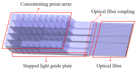
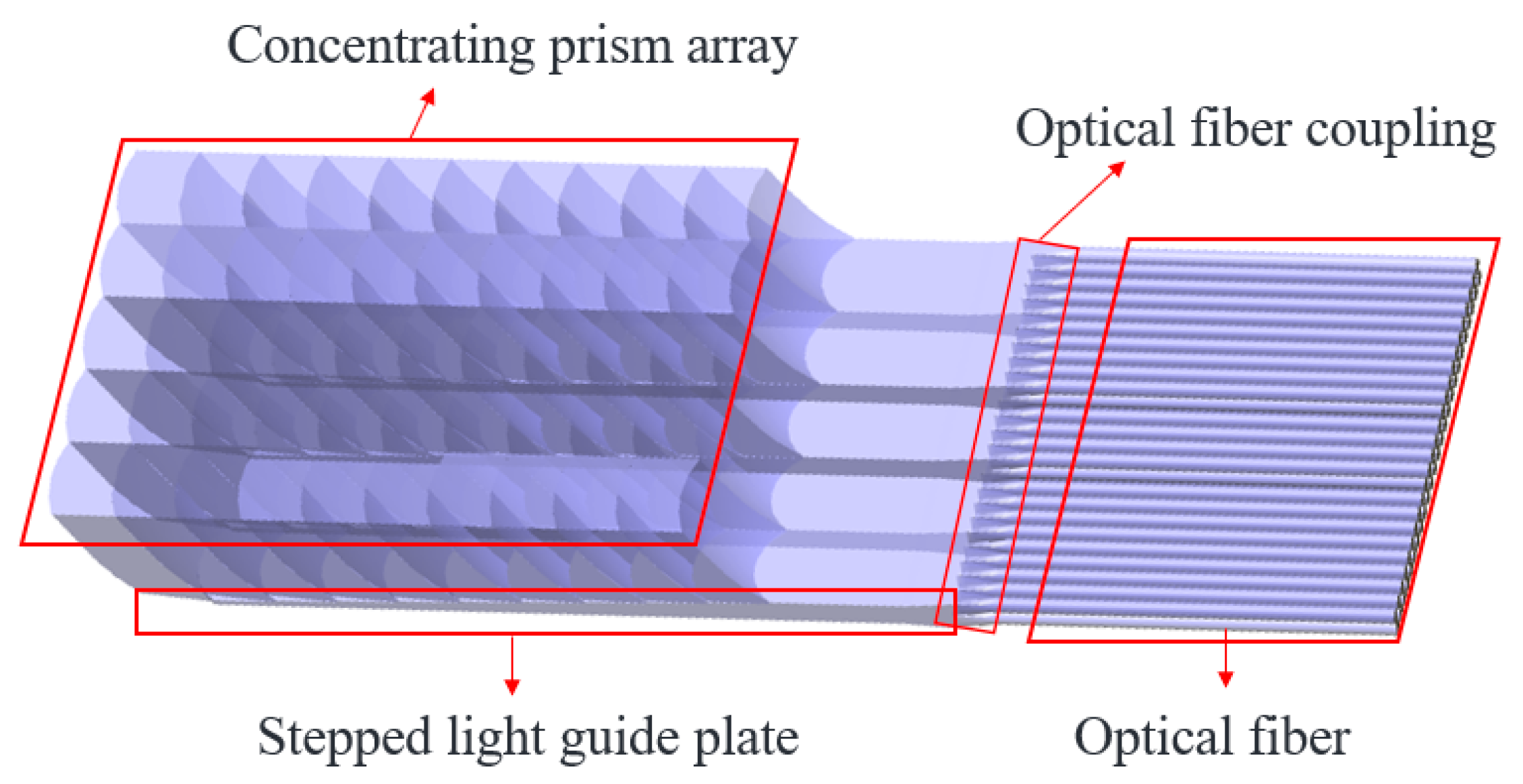
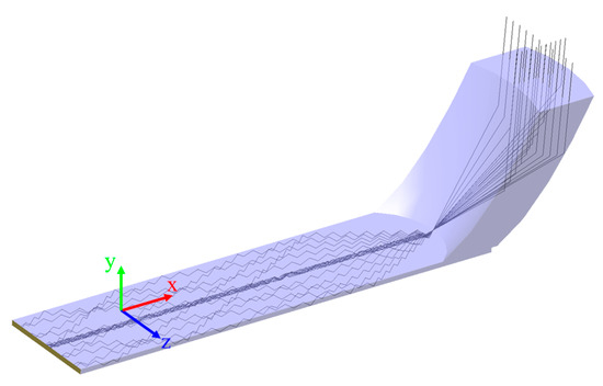
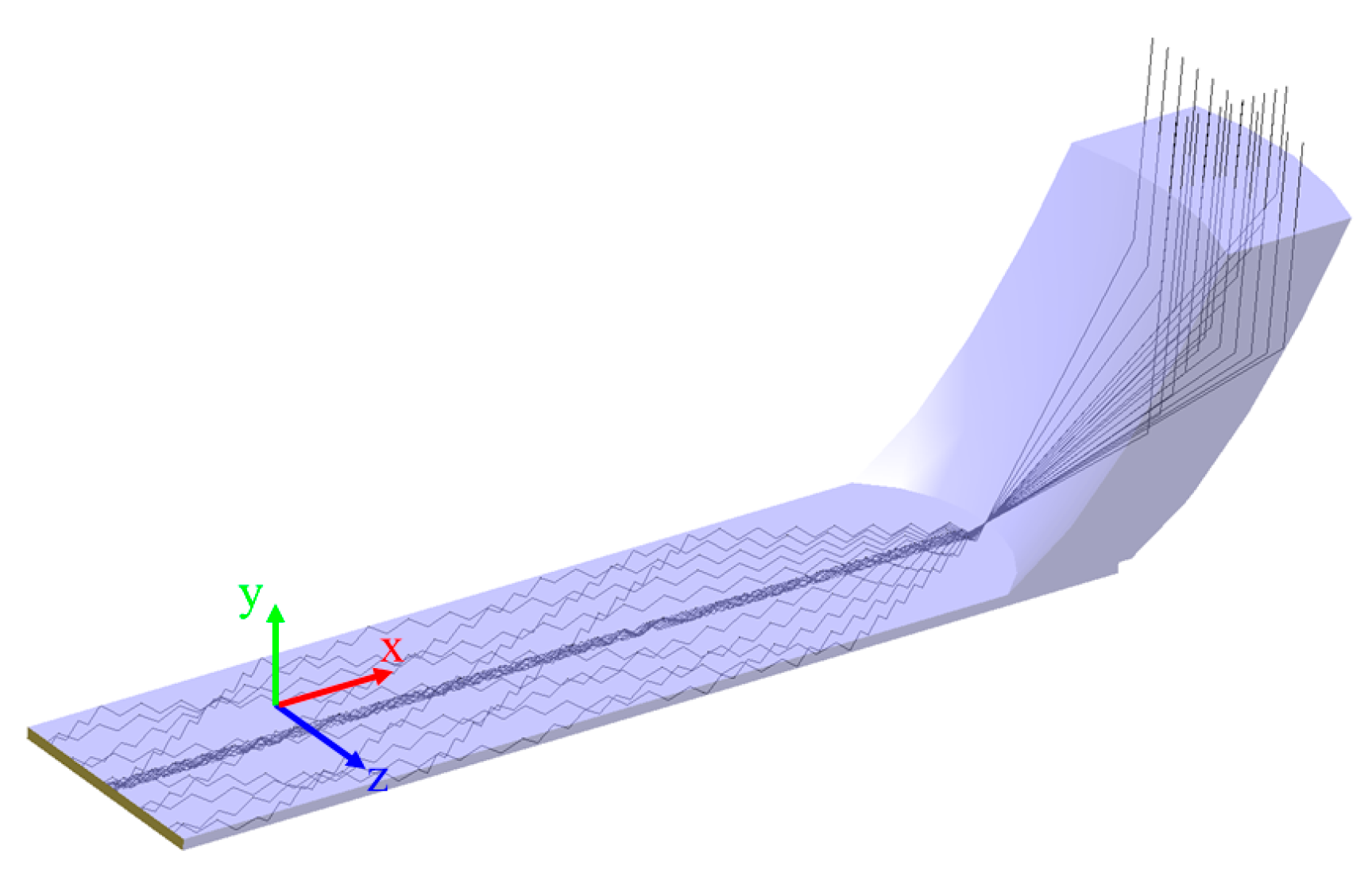
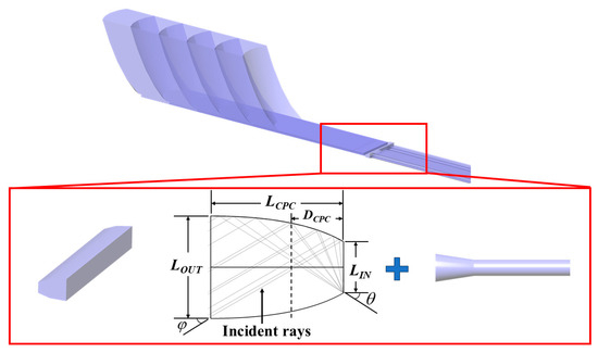
The no-light-leakage stepped integrated concentrator lighting system mainly consists of a concentrator module array, a stepped light guide plate, and optical fibers, as shown in Figure 1. The stepped integrated concentrator module array is positioned above the stepped light guide plate, forming a unified system. The sunlight collected by the stepped integrated concentrator modules propagates through the light guide plate and is coupled into the optical fibers through a fiber coupling structure for illumination. Due to the light-leakage-free integrated design, sunlight does not leak from the light guide plate, which improves the concentrator’s concentration efficiency and the light energy utilization rate of the lighting system. The three key evaluation metrics for the concentrator lighting system are as follows:
Figure 1.
Stepped integrated concentrator lighting system.
In Equation (1), C represents the geometric concentration ratio of the concentrator, which is the ratio of the upper surface area of the concentrator to the side surface area of the light guide plate. When the width of the concentrator remains constant, the geometric concentration ratio can be simplified as the ratio of the effective receiving surface length to the height of the light guide plate. In Equation (2), is the concentration efficiency of the concentrator, which represents the ratio of the energy incident on the upper surface of the concentrator to the energy emitted from the light guide plate. In Equation (3), refers to the light energy utilization efficiency of the lighting system, denotes the attenuation coefficient of the optical fiber, and is the length of the optical fiber.
2.1. Design of Stepped Integrated Concentrator Module
To improve the concentration efficiency and light energy utilization, a stepped integrated concentrator module is proposed. The design steps are as follows: (1) The portion below the focus plane of the paraboloid is removed, and the remaining part of the paraboloid can be expressed as:
This allows sunlight incident along the Y-axis to be focused onto the focal point by the paraboloid. (2) To facilitate subsequent array assembly, the remaining paraboloid is translated along the X-axis, by a distance of . (3) The remaining part is trimmed to a structure with a width of D, thus obtaining a basic stepped integrated concentrator module. To prevent the sunlight entering the stepped integrated concentrator module from leaking at the bottom, the minimum height of the concentrator module is set to:
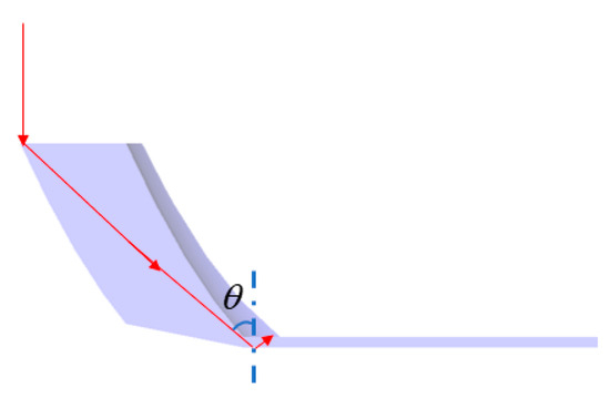
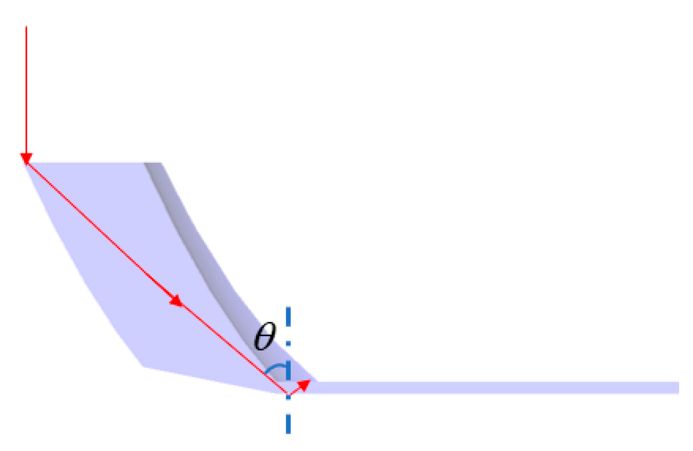
To ensure that the incident light achieves total internal reflection, the reflection angle of the incident light must be greater than the maximum total internal reflection critical angle of the light guide plate , as shown in Figure 2. Therefore, the maximum height of the concentrator module is:
Figure 2.
Ray path diagram at the edge of the concentrator module.
2.2. Coupling Structure and Stepped Light Guide Plate Design
To address the issue of light leakage when the sunlight collected by the concentrator enters the light guide plate, this paper proposes a stepped coupling structure, as shown in Figure 3. The width and tilt angle of the coupling structure can be represented by and , respectively. The tilt angle of the coupling structure can be expressed by Equation (7).
Figure 3.
Simulation diagram of the concentrator module and stepped light guide plate.
To ensure that all the sunlight is coupled into the light guide plate and to achieve a lightweight design, an arc structure can be removed from the original concentrator module. The tilt angle of the arc structure is denoted as .
2.3. Concentrator Module Array
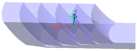
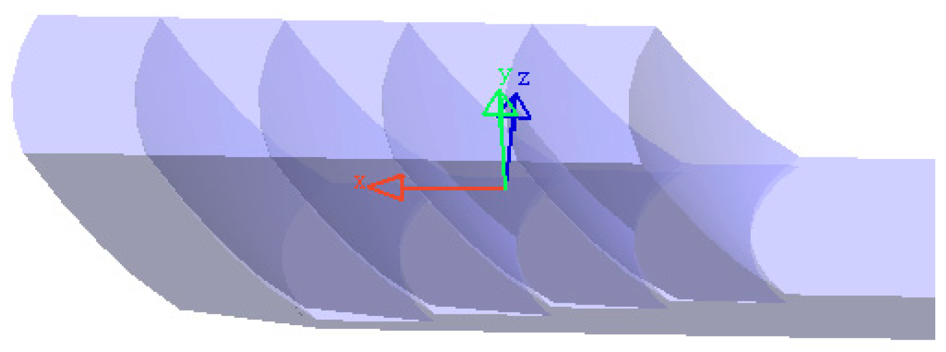
To make better use of sunlight, multiple concentrator modules can be stacked onto the stepped light guide plate to form an integrated system. Figure 4 shows a stepped integrated concentrator that couples five concentrator modules with the stepped light guide plate. This concentrator is designed to be light-leakage-free, which helps improve both the concentration efficiency and the light energy utilization rate.
Figure 4.
Integrated stepped concentrator module.
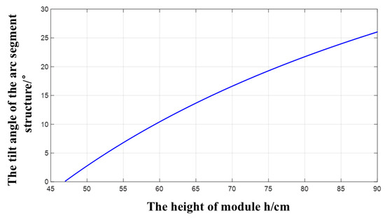
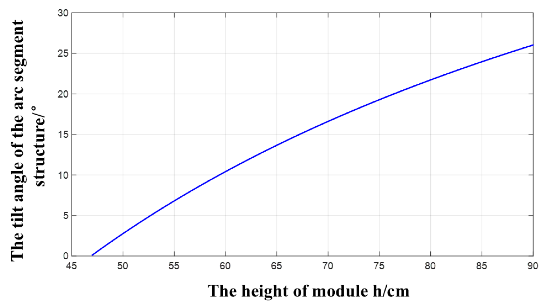
From Figure 4, it can be observed that each module on the stepped integrated concentrator has a different height, resulting in varying tilt angles of the removed arc structure. To explore the relationship between the tilt angle of the arc structure and the height of the concentrator module, a simulation analysis is conducted using MATLAB R2020a (9.8.0.1323502) software based on Equation (7). The results of the simulation are shown in Figure 5. In the simulation, the coupling structure width is set to 0.1 cm, and the paraboloid coefficient is 0.016.
Figure 5.
The relationship between the tilt angle of the arc segment structure and the height of the concentrator module.
From Figure 5, it can be observed that as the number of concentrator modules increases, the tilt angle of the arc segment also increases. This is because, with the addition of concentrator modules, the position of the incident sunlight keeps changing. Therefore, during the array assembly process, as the height of the concentrator modules increases, the tilt angle of the removed arc segment structure should also increase accordingly.
Let the stepped thickness of the light guide plate be denoted as . The number of concentrator modules stacked on the stepped light guide plate can be calculated as:
By substituting Equations (5) and (6) into Equation (8), we can calculate the number of concentrator modules as:
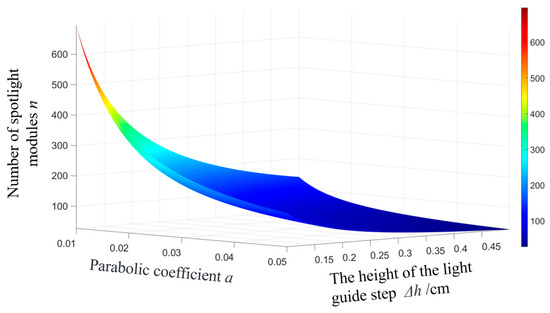
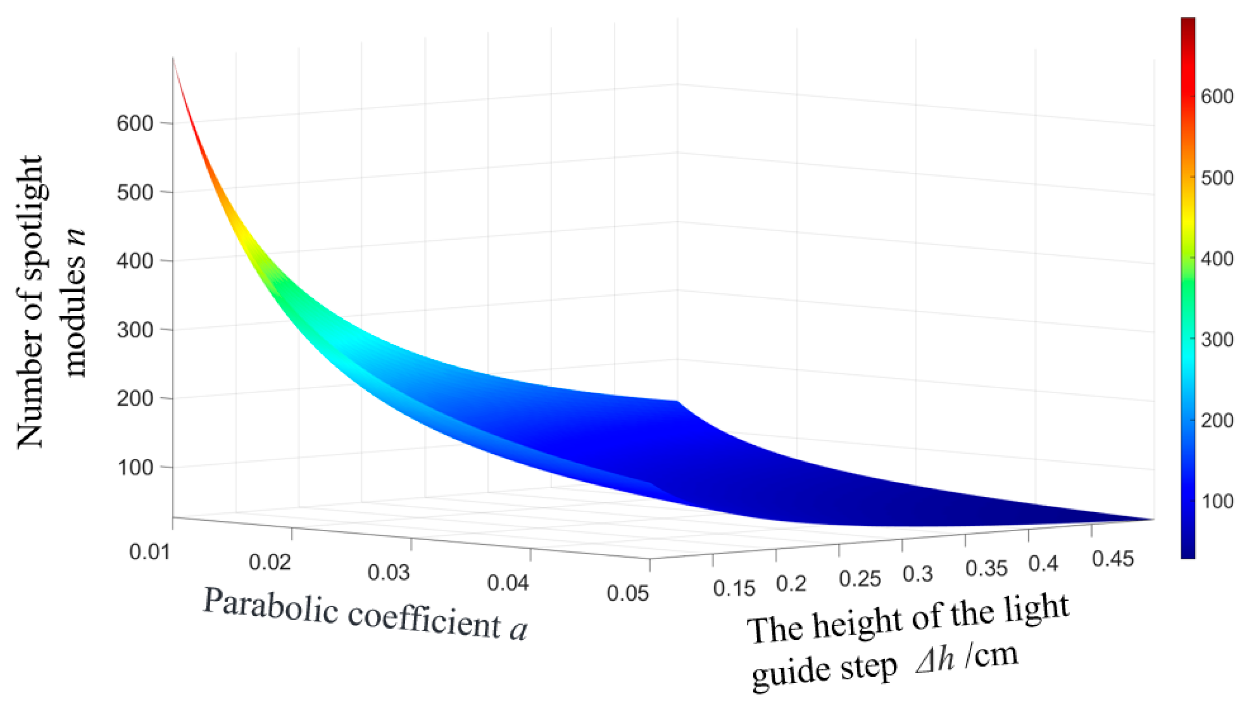
To increase the sunlight receiving area, it is necessary to appropriately increase the number of concentrator modules. From Equation (9), it can be seen that the number of concentrator modules is determined by the paraboloid coefficient and the stepped height of the light guide plate. Next, a simulation analysis is performed to investigate the relationship between the paraboloid coefficient, stepped height, and the number of concentrator modules. The results are shown in Figure 6. In the simulation, the thickness at the far end of the light guide plate is set to 1 cm, the width of each concentrator module is 20 cm. Both the paraboloid coefficient and the stepped height are treated as variables.
Figure 6.
The relationship between the number of concentrator modules, the stepped thickness of the light guide plate, and the paraboloid coefficient.
From Figure 6, it can be observed that the thickness of the light guide plate and the paraboloid coefficient have an inverse proportional relationship with the number of concentrator modules. As the thickness of the light guide plate and the paraboloid coefficient increase, the number of concentrator modules decreases. However, the rate of decrease becomes smaller as the values of these parameters continue to increase.
2.4. Optical Fiber Coupling Structure Design
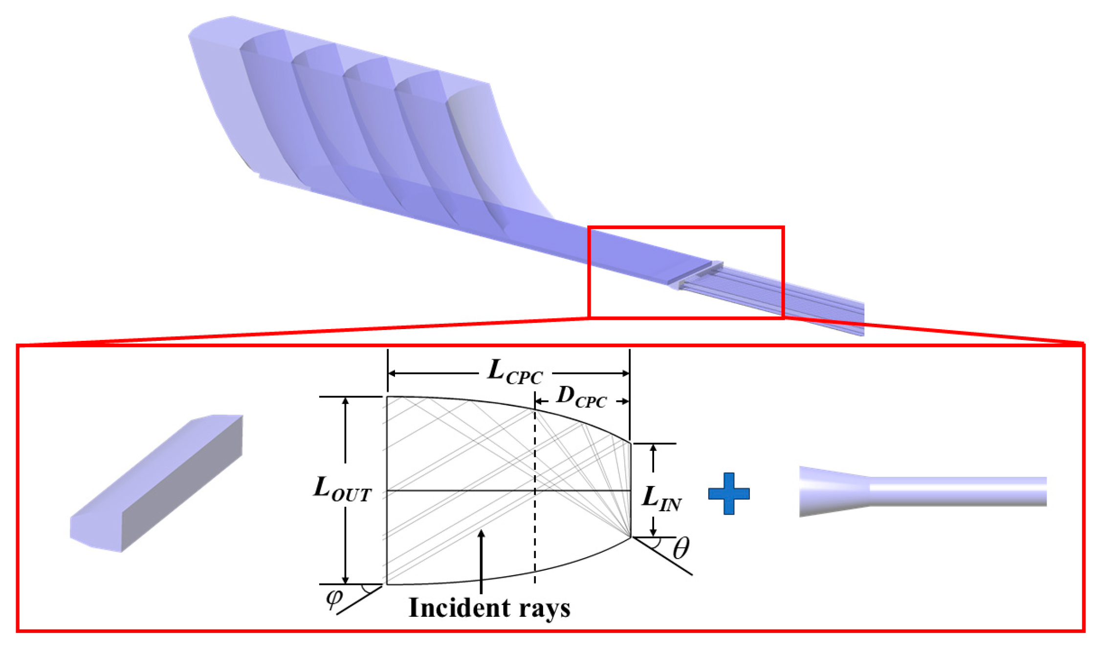
To efficiently couple the emitted light from the end of the light guide plate into the optical fiber, it is necessary to reduce the exit angle of the emitted light. To address this issue, a composite parabolic coupling structure is proposed, as shown in Figure 7. This structure can alter the exit angle of the sunlight in the Y-axis direction. The height of the exit structure can be expressed by Equation (10):
where is the height of the front end of the light guide plate, and is the exit angle, which is also the angle of incidence for the optical fiber. The exit angle of the light rays in the Z-axis direction can be expressed by Equation (11):
Figure 7.
Schematic diagram of the optical fiber coupling structure.
Finally, the range of values for the concentrator module width D can be determined as:
In the above equations, represents the radius of the upper surface of the paraboloid of the outermost concentrator module, and represents the height of the outermost concentrator module.
3. Geometric Concentration Ratio of the Stepped Integrated Concentrator Lighting System
To obtain the maximum geometric concentration ratio of the concentrator, the height of the outermost concentrator module is set equal to . Under this condition, the geometric concentration ratio of the stepped integrated concentrator can be expressed as:
where denotes the surface area perpendicular to the incident sunlight, and represents the receiving surface area of the concentrator.
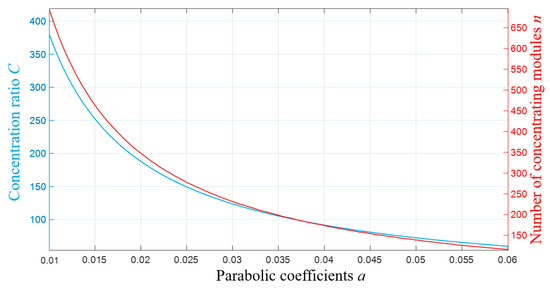
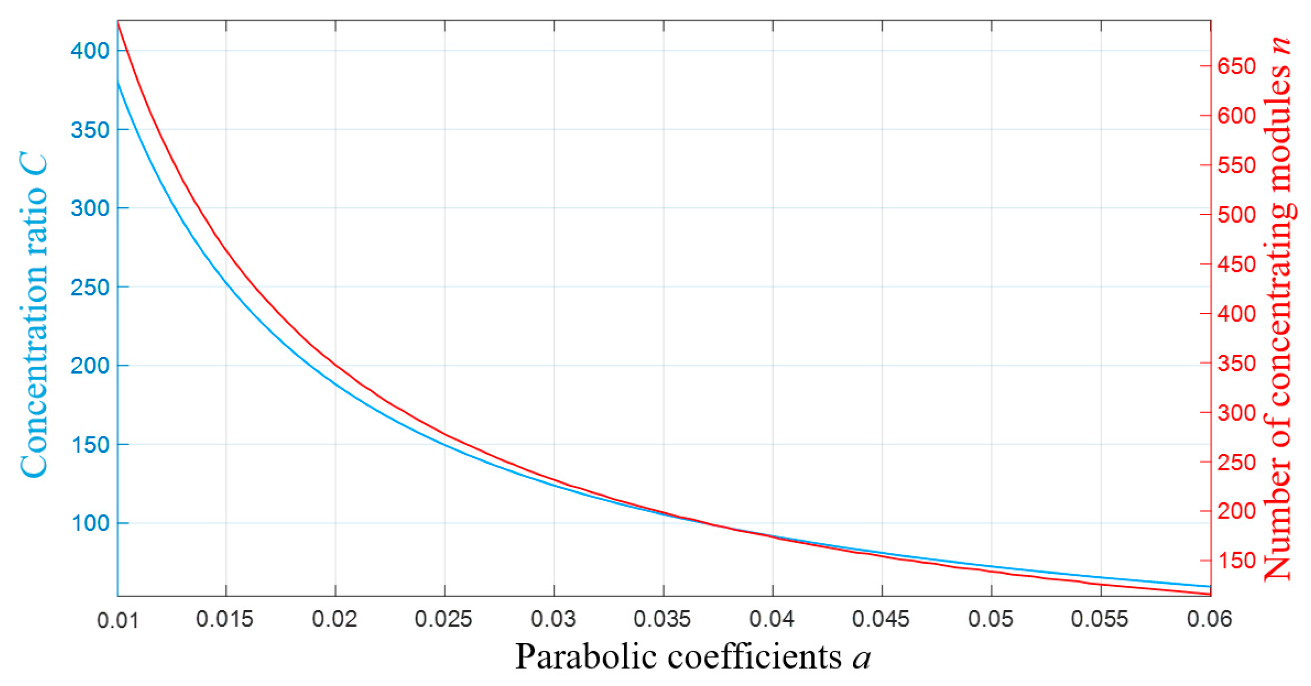
Since the paraboloid coefficient and the stepped height directly determine the number of concentrator modules, they further affect the geometric concentration performance of the lighting system. To investigate the influence of the paraboloid coefficient on the geometric concentration ratio, a simulation was conducted based on Equations (8) and (13). The relationships among the paraboloid coefficient, number of concentrator modules, and geometric concentration ratio are shown in Figure 8. In the simulation, the terminal thickness of the light guide plate is set to 0.1 cm, the step height is 0.1 cm, the edge-ray incident angle is 42°, and the fiber acceptance angle is 31.1°.
Figure 8.
The relationship between the geometric concentration ratio, the number of concentrating modules, and the parabolic coefficient.
As illustrated in Figure 8, both the geometric concentration ratio and the number of concentrator modules decrease progressively with the increase in the paraboloid coefficient. Meanwhile, the rate of decrease in the geometric concentration ratio also gradually diminishes. This indicates that smaller values of the paraboloid coefficient exert a more significant influence on the geometric concentration performance. Moreover, as the paraboloid coefficient tends toward zero, the geometric concentration ratio approaches its maximum value; whereas, when the paraboloid coefficient tends toward infinity, the geometric concentration ratio asymptotically approaches zero.
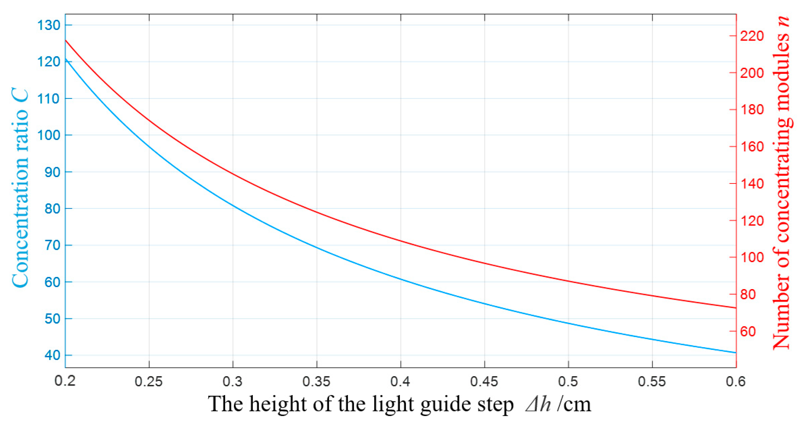
Another factor influencing the geometric concentration ratio is the stepped height of the light guide plate. By setting the paraboloid coefficient of the concentrator to 0.01, a simulation was conducted to analyze the relationship among the stepped height of the light guide plate, the geometric concentration ratio, and the number of concentrator modules. The simulation results are shown in Figure 9.
Figure 9.
Relationship between geometric concentration ratio, number of concentrator modules, and step height.
As shown in Figure 9, the height of the light guide plate exhibits an inverse relationship with both the number of concentrator modules and the geometric concentration ratio. As the step height of the light guide plate increases, the number of concentrator modules decreases, which in turn leads to a continuous decline in the geometric concentration ratio. When the step height increases from 0.2 cm to 0.4 cm, the geometric concentration ratio drops sharply from 123 to 60. However, as the step height further increases from 0.4 cm to 0.6 cm, the geometric concentration ratio decreases more gradually from 60 to 40. This indicates that the rate of decline in geometric concentration ratio slows down progressively as the step height increases.
4. Performance Analysis of the Stepped Integrated Concentrator
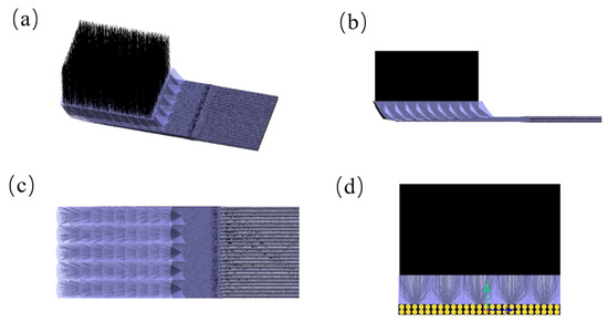
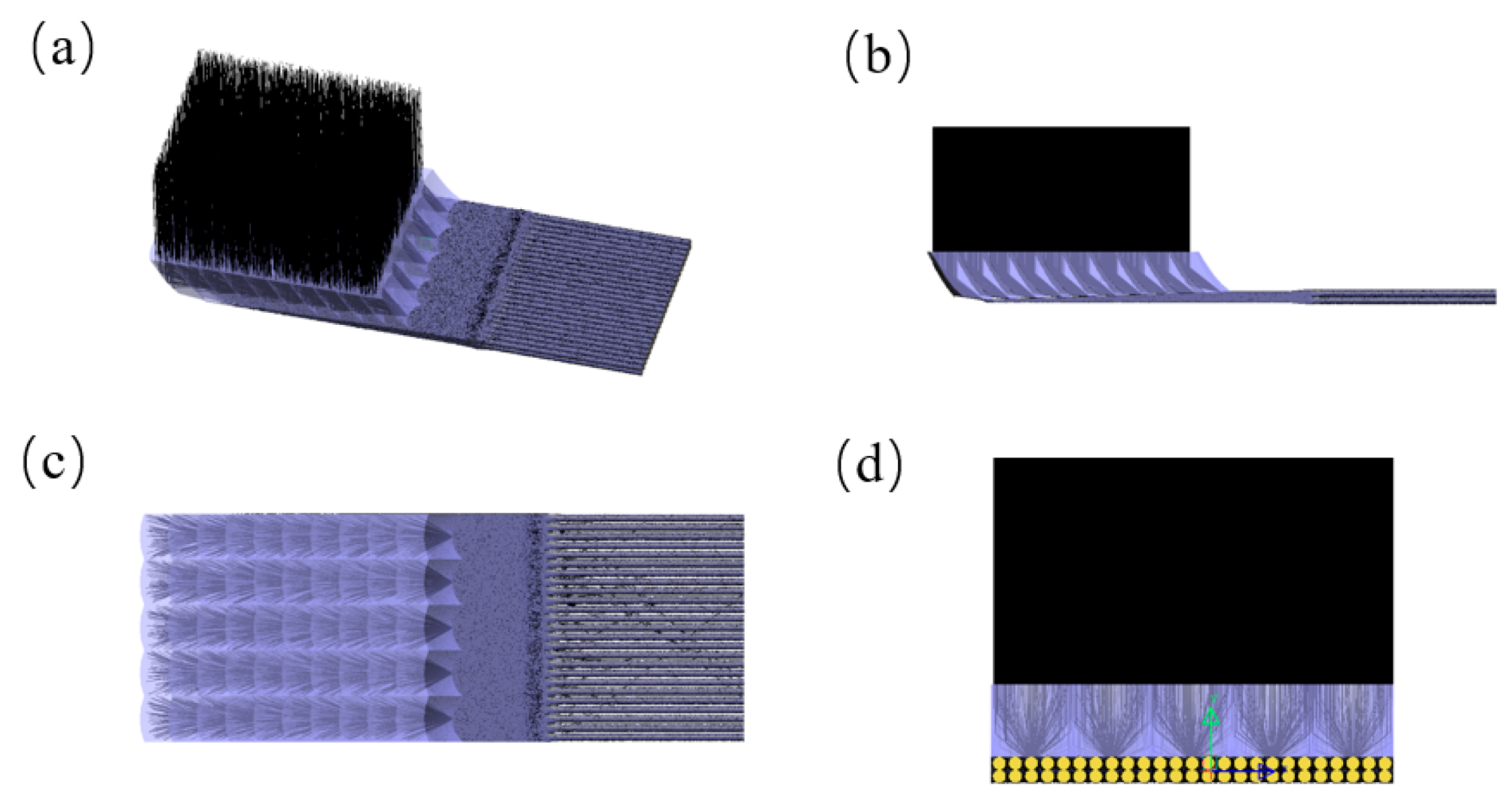
In this section, the proposed stepped integrated no-leakage photovoltaic concentrator is modeled and optically simulated. The simulation parameters for the concentrator modules, stepped light guide plate, and optical fibers are listed in Table 1 and Table 2. The optical simulation is conducted under conditions that account for 0.53° divergence angle of incident sunlight, Fresnel surface losses, and the optical properties of materials. The results are shown in Figure 10. The simulation demonstrates that the proposed structure can efficiently collect incident sunlight, with virtually no light leakage observed from the edges of the light guide plate. To address thermal effects during the concentration process, a dynamic regulation strategy for the geometric concentration ratio is proposed. This can be achieved by adjusting the number of concentrator modules or the thickness of the light guide plate, effectively mitigating the risk of overheating in photovoltaic cells.
Table 1.
Parameters for optical fiber simulation.
Table 2.
Parameters for concentrator design.
Figure 10.
Optical Ray-Tracing Simulation of the Concentrator Lighting System. (a) 3D view; (b) X–Z view; (c) X–Y view; (d) Y–Z view.
4.1. Height of the Outermost Concentrator Module
In theoretical calculations of geometric concentration ratio, it is commonly assumed that the system can achieve its maximum geometric concentration ratio when the outermost concentrator module reaches its maximum height. However, simulation results reveal that due to the 0.53° divergence angle of sunlight, an excessively tall outermost concentrator module may actually reduce the concentration efficiency. To optimize system performance, it is necessary to further investigate the influence mechanism of the outermost concentrator module height on both the geometric concentration ratio and the concentration efficiency. Therefore, the original expressions for calculating the number of concentrator modules and the geometric concentration ratio are revised to account for the effect of solar divergence angle, resulting in new formulations. These revised expressions enable a quantitative analysis of the concentration characteristics under different module height configurations.
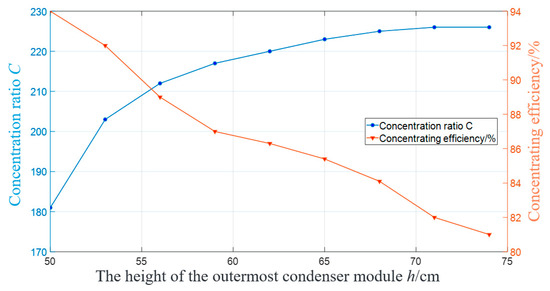
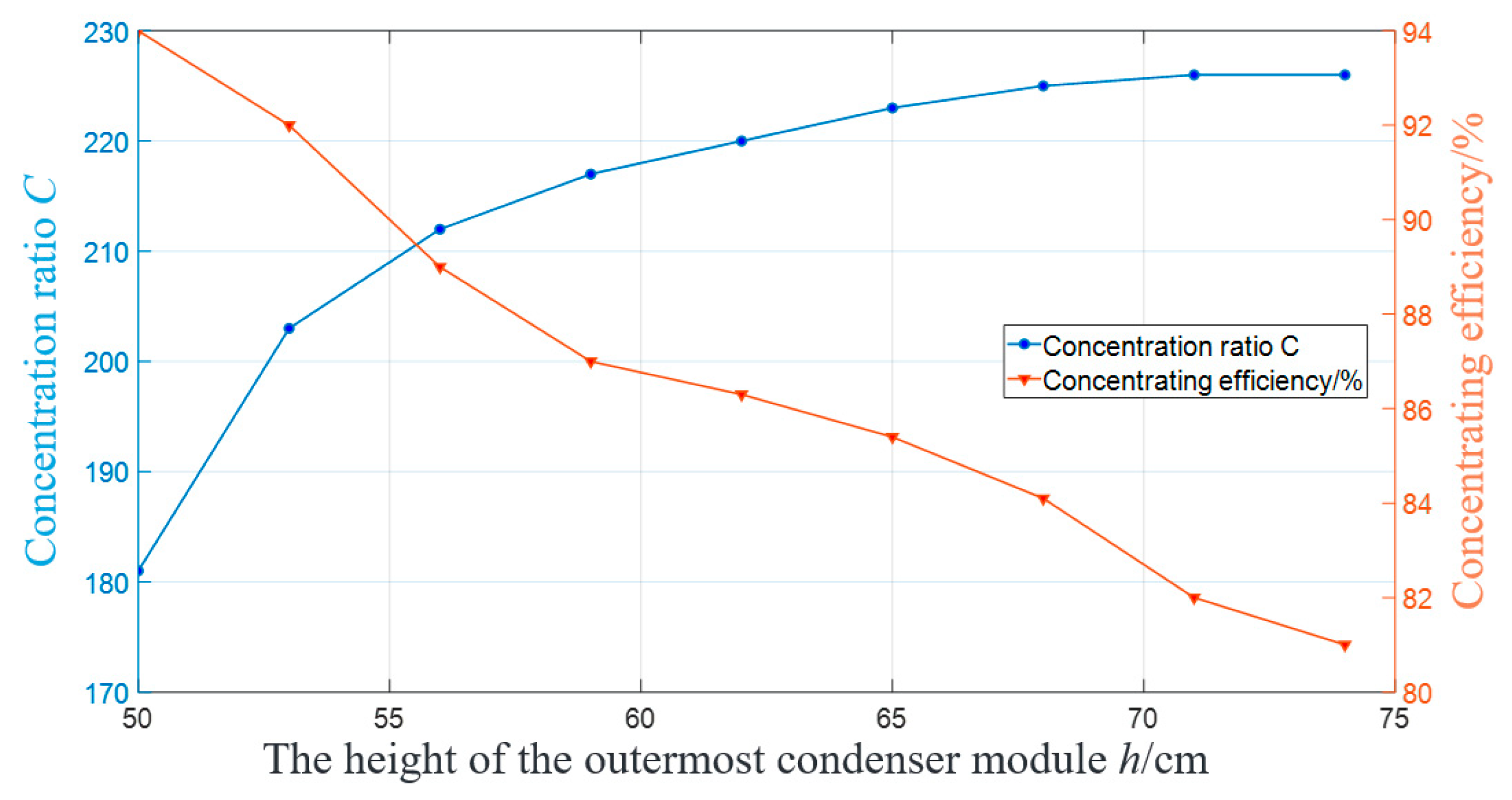
Simulations of the outermost concentrator module height, geometric concentration ratio, and optical efficiency are conducted as shown in Figure 11. Based on Equations (4) and (6), the allowable range of the outermost concentrator module height is determined and set as the horizontal axis of the graph. The simulation parameters used in this analysis are listed in Table 1. This simulation provides a quantitative understanding of how variations in the outermost module height affect both the geometric concentration ratio and the optical efficiency, offering guidance for optimizing the structural design of the concentrator system under realistic solar divergence conditions.
Figure 11.
Influence of the outermost concentrator module height on optical efficiency and geometric concentration ratio.
In the simulation analysis, the height range of the outermost concentrator module is jointly determined by Equation (5), which defines the range of the horizontal axis in Figure 11. Through a systematic investigation of the influence of the outermost module height on the performance of the concentrator, the following key conclusions are obtained: As the height of the outermost concentrator module decreases, the concentration efficiency exhibits a monotonically increasing trend, while the geometric concentration ratio correspondingly decreases. When the outermost module height is reduced to 50 cm, the system achieves its maximum concentration efficiency of 94%, with a corresponding geometric concentration ratio of 50.
4.2. Stepped Height of the Light Guide Plate
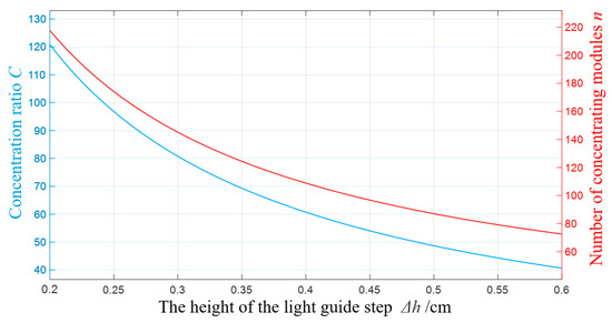
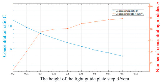
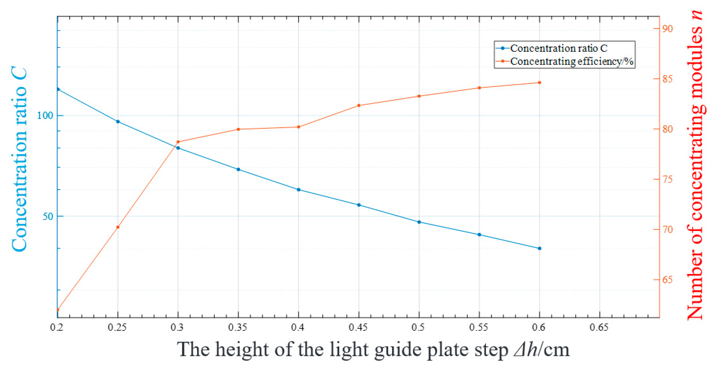
Due to the 0.53° divergence angle of actual sunlight, part of the incident light may fail to couple effectively as a result of the stepped height of the light guide plate, leading to two primary mechanisms of optical loss: (1) partial light rays refract and escape beneath the concentrator module; (2) other rays fail to enter the light guide plate due to a mismatch between the step height and the angle of incidence. To optimize the performance of the concentrator system, it is necessary to investigate the influence of step height on both the geometric concentration ratio and optical efficiency. For this purpose, this study conducts simulation analyses of the concentrator lighting system under various step heights(with simulation parameters listed in Table 1 and Table 2). A quantitative relationship between the step height and the system’s concentration efficiency and geometric concentration ratio is ultimately established, as shown in Figure 12, providing a theoretical basis for the structural optimization of the concentrator.
Figure 12.
Influence of step height on geometric concentration ratio and concentration efficiency.
In the simulation analysis, the variation trends of geometric concentration ratio and concentration efficiency are derived. As shown in Figure 12, the performance parameters of the stepped hybrid concentrator exhibit distinct characteristics with respect to changes in step height: the concentration efficiency continuously increases as the step height increases, while the geometric concentration ratio shows an opposite trend (see the analysis in Section 3). Specifically, when the step height is 0.2 cm, the system achieves a maximum geometric concentration ratio of 120, corresponding to a concentration efficiency of 62.70%. As the step height increases to 0.5 cm, the concentration efficiency rises to 84.62%, whereas the geometric concentration ratio decreases to 40. These results indicate a mutual constraint between the two key performance indicators of the concentrator system: increasing the step height improves optical efficiency but simultaneously reduces the geometric concentration ratio, highlighting the need for trade-off optimization in structural design.
4.3. Width of the Stepped Light Guide Plate
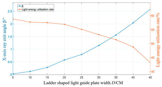
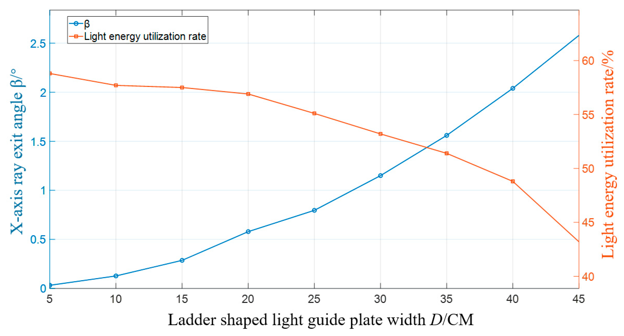
The width of the light guide plate affects the exit angle of the incident sunlight, thereby influencing the overall light energy utilization efficiency of the concentrator-based lighting system. To investigate the optimal energy utilization performance of the system, we proceed to analyze the impact of the stepped light guide plate width on the performance of the entire lighting system.
As shown in Figure 13, simulation analyses of the light guide plate width, the exit angle of light in the Z-axis direction, and the light energy utilization efficiency were conducted. The range of the stepped light guide plate width is determined and set as the horizontal axis of the graph. The simulation parameters are listed in Table 1. The results indicate that as the width of the light guide plate increases, the exit angle of the light rays exhibits a clear upward trend, with the rate of increase accelerating. This growing exit angle increasingly affects the system’s light energy utilization. At the same time, the light energy utilization efficiency continuously declines with the increasing width of the guide plate, and the decline becomes particularly pronounced when the width exceeds 30 cm. These findings suggest that the system demonstrates better energy utilization performance at smaller guide plate widths. However, as the width of the stepped light guide plate increases, the incident angle of light also increases, resulting in reduced energy utilization efficiency.
Figure 13.
Influence of light guide plate width on exit angle and light energy utilization efficiency.
4.4. Experimental Analysis
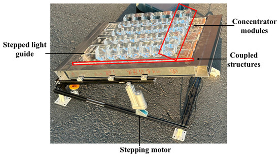
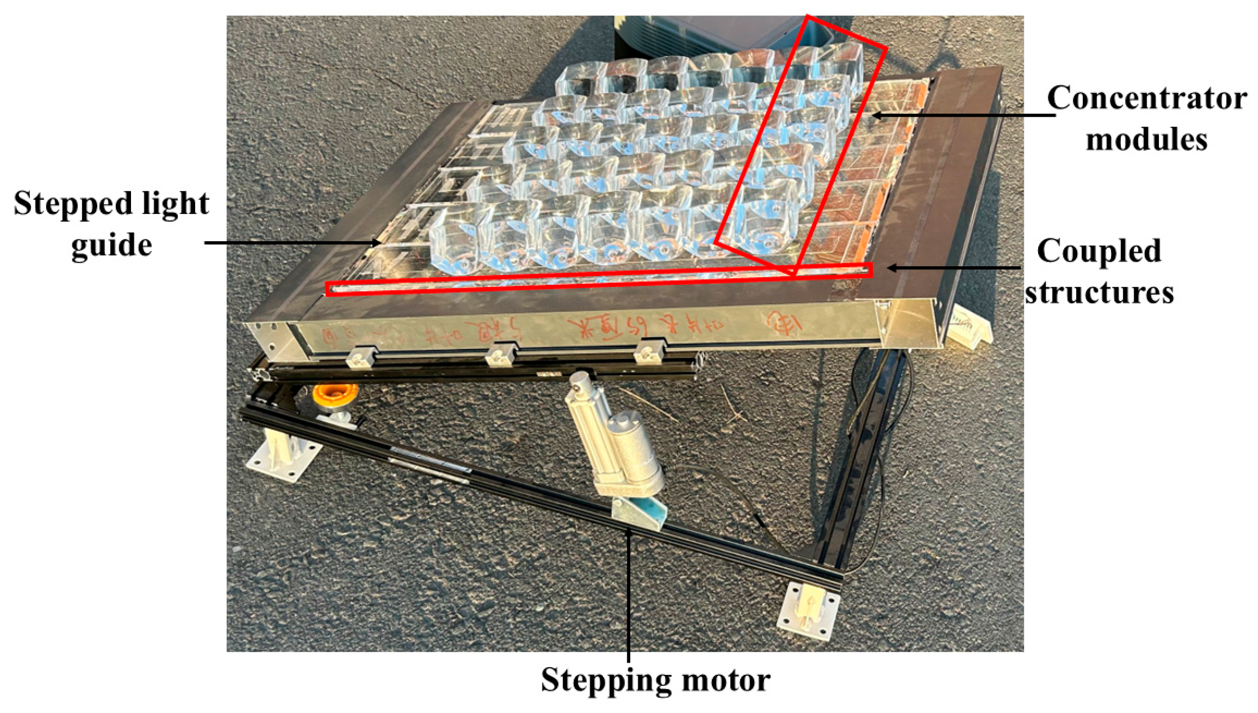
To verify the accuracy of the simulation results described above, the concentrator module array and the stepped light guide plate of the concentrator lighting system were fabricated and subjected to experimental analysis. The fabricated concentrator modules and the experimental setup are shown in Figure 14. Subject to experimental conditions, the sunlight possesses a ±0.26° divergence angle and an Air Mass 1.5 Solar Spectrum [25]. PMMA material is used to fabricate the collector through high-precision mold injection molding because of its good optical and mechanical properties of the titania after natural weather [26], and the light guide plate is processed with the help of a five-axis computerized numerical control machine (Nanotech 350FG from Moore Nanotechnology Systems, LLC, Swanzey, NH, USA). The optical power of the emergent rays can be detected by an optical power meter of the type PM400K5, Thorlabs, Newton, NJ, USA. The detailed parameters of the concentrator modules and the stepped light guide plate used in the experiment are listed in Table 3. The concentrator used in the experiment is placed in an open area outdoors without any obstruction. The stepping motor is used to control the elevation angle of the concentrator to track the sun location. A 5 × 10 array of concentrator modules is manufactured through injection molding and are encapsulated with a light guide plate to ensure that sunlight can be coupled into the light guide plate for propagation. Experiments are conducted during the period from 11:00 to 13:00, when sunlight is relatively strong, and experimental data from three different clear weather conditions are selected for analysis.
Figure 14.
Experimental setup diagram of stepped integrated photovoltaic concentrator.
Table 3.
Parameters of spotlight module and light guide plate.
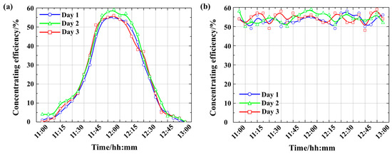
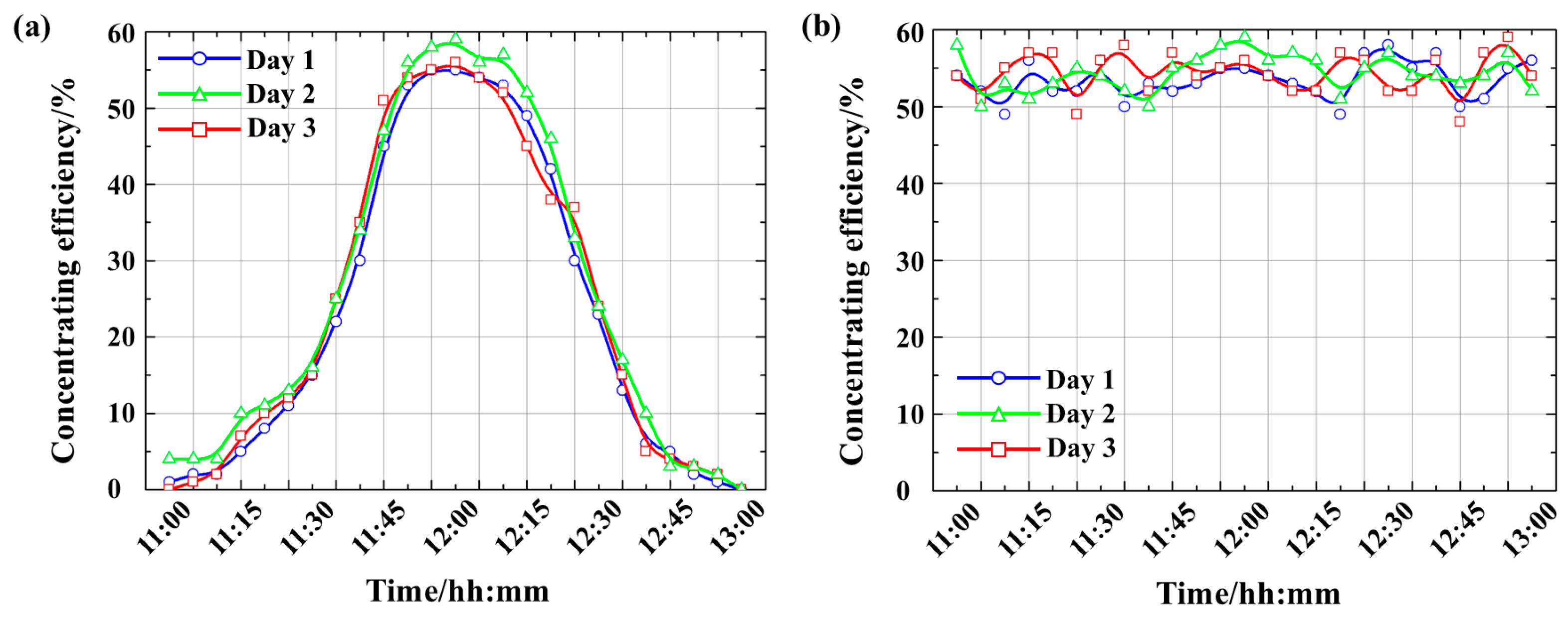
During the experiment, the upper surface of the concentrator was first aligned perpendicular to the sunlight at 12:00 noon. The sunlight was then guided through the stepped coupling entrance, propagated within the light guide plate, and finally reached the front end of the plate. At different time intervals, an illuminance meter was used to measure the illuminance on both the upper surface of the concentrator module and the front end of the light guide plate. The concentration efficiency at each time point was calculated. To ensure experimental accuracy, measurements were conducted continuously over a period of three days. The resulting time-dependent concentration efficiency is shown in Figure 15. The concentrating efficiency of the system first increases and then decreases over the course of the day, reaching a maximum value of 54.6% at 12:00 noon under circumstance of the concentrator without tracker, as shown in Figure 15a. This indicates that without the use of a tracker, the concentrator can maintain a concentrating efficiency of over 50% for 30 min. Beyond 30 min, the concentration efficiency drops sharply, reflecting the design characteristic of being optimized for parallel light incidence. Figure 15b shows the variation in the concentrating efficiency over time when a tracker is used, which shows the concentration efficiency remains stable between 50% and 60%.
Figure 15.
Concentrating efficiency of the concentrator at different times (a) without tracker and (b) with tracker.
5. Conclusions
This paper proposes a novel stepped integrated no-leakage concentrator lighting system to address the issues of insufficient light energy utilization and light leakage commonly found in existing daylighting systems. By constructing an integrated structure composed of a concentrator module array and a stepped light guide plate and incorporating a composite parabolic coupling design, the system achieves efficient solar energy collection and guiding, significantly enhancing both concentration efficiency and energy utilization. Based on the principles of geometric optics, a systematic analysis was conducted to examine the influence of key parameters—including the paraboloid coefficient, step height, and number of concentrator modules—on the geometric concentration ratio and optical efficiency. The underlying mechanisms by which these parameters affect system performance were clearly identified. Simulation results demonstrate that the proposed system possesses excellent light-guiding capability and high optical efficiency, achieving a maximum concentration efficiency of 94% and a geometric concentration ratio of 50, while effectively eliminating the light leakage issues present in traditional designs. An experimental prototype was fabricated and tested under real-sun conditions. Measurements showed that the system reached a concentration efficiency of 54.6% at noon, which is in good agreement with simulation results, thereby validating the feasibility and superior performance of the proposed structure. The findings indicate that the stepped integrated no-leakage concentrator lighting system offers significant advantages in enhancing light energy utilization and reducing leakage losses, providing a practical and effective technical solution for daylighting and energy-saving lighting in green buildings. In future work, the detailed experimental analysis of the thermal management of the unit will also be conducted.
Author Contributions
Conceptualization, J.X. and P.Y.; methodology, J.X. and Y.H.; software, X.Z.; validation, B.Z., S.D. and Y.M.; formal analysis, J.S.; investigation, B.L. and Y.Y.; writing—original draft preparation, S.X. and S.L.; funding acquisition, P.Y. All authors have read and agreed to the published version of the manuscript.
Funding
This research was funded by the Jilin Province Industry Technology Research and Development Project, grant number 2024C007-1, Jilin Provincial Department of Science and Technology.
Data Availability Statement
Data will be made available on request.
Conflicts of Interest
The authors declare that they have no known competing financial interests or personal relationships that could have appeared to influence the work reported in this paper.
Abbreviations
The following abbreviations are used in this manuscript:
| CPCs | Compound Parabolic Concentrators |
| LFR | Linear Fresnel Reflector |
| PLCs | Planar Light guide plates |
References
- Lin, J.; Wang, L.; Meng, X.; Li, W.; Ren, N.; Tao, L.; Xiao, J.; Jing, Q.; Song, Y.; Zhao, H. Improved light absorption enables highly efficient carbon dots luminescent solar concentrator. Appl. Phys. Lett. 2025, 126, 043904. [Google Scholar] [CrossRef] [Scilit]
- Li, W.; Lin, J.; Li, J.; Jing, Q.; Ren, N.; Xiao, J.; Zhao, H.; Song, Y.; Vomiero, A. Wearable luminescent solar concentrators based on carbon dots crosslinked hydrogels. Nano Energy 2026, 148, 111674. [Google Scholar] [CrossRef] [Scilit]
- Yin, P.; Lv, J.; Wang, X.; Huang, R. A spectral splitting planar solar concentrator with a linear compound parabolic lightguide for optical fiber daylighting. Renew. Energy 2021, 179, 778–787. [Google Scholar] [CrossRef] [Scilit]
- Solovyov, A.K.; Rimshin, V.I. Improving of the buildings daylightings standardization. Light Eng. 2025, 33, 57–63. [Google Scholar] [CrossRef] [Scilit]
- Vu, N.H.; Shin, S. Flat Optical Fiber Daylighting System with Lateral Displacement Sun-Tracking Mechanism for Indoor Lighting. Energies 2017, 10, 1679. [Google Scholar] [CrossRef] [Scilit]
- Lv, Y.; Xia, L.; Li, M.; Wang, L.; Su, Y.; Yan, J. Techno-economic evaluation of an optical fiber based hybrid solar lighting system. Energy Convers. Manag. 2020, 225, 113399. [Google Scholar] [CrossRef] [Scilit]
- Kaur, K.; Rajagopalan, P.; Woo, J.; Garg, H. Harnessing sunlight for indoor illuminance using a Fresnel lens-based daylighting system. Energy Build. 2025, 342, 115877. [Google Scholar] [CrossRef] [Scilit]
- Kavuthimadathil, S.; Ramamurthy, K. Design of a passive fibre optic system with non-tracking imaging CPC collector and optimised fibre bundle for indoor illumination. J. Build. Eng. 2025, 107, 112662. [Google Scholar] [CrossRef] [Scilit]
- Yin, P.; Xu, X.; Jiang, Z.; Hai, Y. Ray-leakage-free discal solar concentrators of a novel design. Opt. Commun. 2017, 405, 378–386. [Google Scholar] [CrossRef] [Scilit]
- Vistas, C.R.; Liang, D.; Catela, M.; Costa, H.; Garcia, D.; Tibúrcio, B.D.; Almeida, J. Fresnel Lens Solar Pumping for Uniform and Stable Emission of Six Sustainable Laser Beams under Non-Continuous Solar Tracking. Sustainability 2023, 15, 8218. [Google Scholar] [CrossRef] [Scilit]
- Ma, X.; Jin, R.; Liang, S.; Liu, S.; Zheng, H. Analysis on an optimal transmittance of Fresnel lens as solar concentrator. Sol. Energy 2020, 207, 22–31. [Google Scholar] [CrossRef] [Scilit]
- Johnsen, H.J.D.; Aksnes, A.; Torgersen, J. High-performance stationary solar tracking through multi-objective optimization of beam-steering lens arrays. Opt. Express 2020, 28, 20503–20522. [Google Scholar] [CrossRef] [Scilit] [PubMed]
- Mashaal, H.; Feuermann, D.; Gordon, J.M. Expansive scope of aplanatic concentrators and collimators. Appl. Opt. 2019, 58, F14–F20. [Google Scholar] [CrossRef] [Scilit]
- Jiang, Y.; Xie, Q.; Qu, E.; Ren, L.; Liang, J.; Wang, J. Multi-wavelength multi-focus Fresnel solar concentrator with square uniform irradiance: Design and analysis. Appl. Opt. 2019, 58, 5206–5212. [Google Scholar] [CrossRef] [Scilit]
- El Ayane, S.; Ahaitouf, A. Performance Analysis of a Micro-Photovoltaic Concentrator Designed for Automotive Applications. Energies 2024, 17, 6470. [Google Scholar] [CrossRef] [Scilit]
- Metcalf, I.; Chen, G.; Cooper, T.A. Toward a best-form CPC-like nonimaging optical concentrator. Opt. Express 2022, 30, 44556–44568. [Google Scholar] [CrossRef] [Scilit]
- Liu, T.; Wang, J.; Bing, Y.; Yang, F.; Feng, W.; Wang, D. Simulation study of concentrating characteristics of trough solar collector. Acta Energiae Solaris Sin. 2017, 38, 3202–3209. [Google Scholar]
- Ceballos, M.A.; Fernández, E.F.; Rodrigo, P.M.; Valera, Á.; Pérez-higueras, P.J.; Almonacid, F. High-performance 4096× ultra-high CPV module based on multiple concentrator units and optical guides. Opt. Lett. 2021, 46, 4188–4191. [Google Scholar] [CrossRef] [Scilit]
- Yin, P.; Xu, X.; Jiang, Z. Ray-leakage-free planar solar concentrator featuring achromatic hybrid collectors and innovative secondary optical elements. Opt. Commun. 2017, 402, 678–689. [Google Scholar] [CrossRef] [Scilit]
- Wu, H.-Y.; Chu, S.-C. Ray-leakage-free sawtooth-shaped planar lightguide solar concentrators. Opt. Express 2013, 21, 20073–20089. [Google Scholar] [CrossRef] [Scilit] [PubMed]
- Xie, P.; Lin, H.; Liu, Y.; Li, B. Total internal reflection-based planar waveguide solar concentrator with symmetric air prisms as couplers. Opt. Express 2014, 22, A1389–A1398. [Google Scholar] [CrossRef] [Scilit]
- Teng, T.-C.; Kuo, C.-H.; Li, Y.-J. Planar solar concentrator composed of stacked waveguides with arc-segment structures and movable receiving assemblies. Opt. Express 2020, 28, 34362–34377. [Google Scholar] [CrossRef] [Scilit]
- Yin, P.; Xu, X.; Jiang, Z.; Zhang, L. Design Method of Solar Concentrator Based on Elliptic Type Monge-Ampére Equations. Acta Opt. Sin. 2017, 37, 0922002. [Google Scholar] [CrossRef] [Scilit]
- Ramachandran, A.M.; Asok, A. Single elemental planar light concentrator using skewed V-groove optics. Results Eng. 2024, 24, 102923. [Google Scholar] [CrossRef] [Scilit]
- Solar Spectra. Available online: http://rredc.nrel.gov/solar/spectra/am1.5/ (accessed on 23 February 2026).
- Ali, U.; Karim, K.J.B.A.; Buang, N.A. A Review of the Properties and Applications of Poly (Methyl Methacrylate) (PMMA). Polym. Rev. 2015, 55, 678–705. [Google Scholar] [CrossRef] [Scilit]

Disclaimer/Publisher’s Note: The statements, opinions and data contained in all publications are solely those of the individual author(s) and contributor(s) and not of MDPI and/or the editor(s). MDPI and/or the editor(s) disclaim responsibility for any injury to people or property resulting from any ideas, methods, instructions or products referred to in the content. |
© 2026 by the authors. Licensee MDPI, Basel, Switzerland. This article is an open access article distributed under the terms and conditions of the Creative Commons Attribution (CC BY) license.