


Abstract
White Rabbit (WR) is a technology based on fiber-optic networks that enables sub-nanosecond-level time synchronization and deterministic Ethernet data transmission among distributed devices. To investigate the transmission characteristics of WR technology over free-space optical links, this paper reports point-to-point single-link ranging experiments for WR over an approximately 1 km near-ground free-space optical link. For the 1 km fiber-optic link and the 1 km free-space optical link (scintillation index = 0.063), the intermediate precision of ranging after a power-cycle reboot is measured to be 5.829 mm (1σ) and 9.689 mm (1σ), respectively, while the ranging precision is 0.267 mm (1σ) and 1.353 mm (1σ), respectively. As the scintillation index of the free-space optical link increases from 0.063 to 0.168, the ranging precision degrades from 1.353 mm (1σ) to 2.221 mm (1σ). The results demonstrate that under a scintillation index of 0.063, both the intermediate precision of ranging after a power-cycle reboot and the ranging precision over the 1 km free-space optical link degrade compared with those of the 1 km fiber-optic link. Specifically, the intermediate precision of ranging after power-cycle reboot degrades to 1.66 times that of the fiber-optic link, and the ranging precision degrades to 5.07 times that of the fiber-optic link. Furthermore, it is also observed in this 1 km free-space optical link experiment that as the scintillation index increases from 0.063 to 0.168, the one-sigma standard deviation of ranging precision rises from 1.353 mm to 2.221 mm.
1. Introduction
Time synchronization is a key technology for aligning the independent clocks of multiple nodes with a reference clock source in distributed systems. Network-based time-synchronization technologies mainly include the Network Time Protocol (NTP), Precision Time Protocol (PTP), and the White Rabbit (WR) time-synchronization technique. NTP [1] generates timestamps when data packets enter the operating-system kernel. Affected by interrupt handling and protocol-stack latency, it achieves a typical accuracy at the millisecond level. PTP [2] applies timestamps on the Gigabit Media Independent Interface (GMII) bus between the Media Access Control (MAC) layer and the Physical Coding Sublayer (PCS). It circumvents the latency introduced by the MAC layer and upper software stacks, and delivers nanosecond-level accuracy. WR [3] supports thousands of distributed nodes with a single-hop transmission distance exceeding 10 km, yielding sub-nanosecond synchronization accuracy.
The White Rabbit (WR) technology was proposed by the European Organization for Nuclear Research (CERN) in collaboration with multiple enterprises and research institutions. It was developed to provide deterministic data transmission for the Large Hadron Collider accelerator chain, achieving sub-nanosecond synchronization accuracy and picosecond-level synchronization precision. With the popularization of WR technology across various scientific fields, WR has gradually become a critical technology supporting cutting-edge scientific research [4,5], smart power grids [6,7], financial infrastructures [8,9], and national strategic security [10,11,12]. At present, WR time-synchronization technology is continuously evolving toward long-distance cascading [13], high-precision calibration [14], and flexible wireless-channel access [15].
According to carrier types, wireless time-synchronization technologies are mainly divided into two categories: microwave carriers and free-space optical carriers. Reference [16] realized WR time and frequency transmission over millimeter-wave carriers (71–76 GHz). Reference [17] evaluated the WR time-transmission performance in a 5G Ultra-Reliable Low-Latency Communication (URLLC) network (2.45 GHz). The results show that the Allan deviation (ADEV), time deviation (TDEV) and phase variation degrade slightly but still satisfy the sub-nanosecond frequency-transmission specifications of WR. Reference [18] verified a wavelength-division-multiplexing-based multi-channel free-space optical synchronization scheme for WR under laboratory conditions. A maximum data rate of 118 Gbps was achieved at a distance of 1.5 m, while synchronization accuracy was maintained at the sub-nanosecond level. References [19,20] demonstrated a 100 m free-space optical link constructed by mirror folding, where the WR time offset reached 17.7 ps at an integration time of 1 s. Reference [21] performed synchronization-performance tests by imposing power fluctuations on WR signals using a scintillation playback system to simulate intensity time-series variations induced by different turbulence conditions. Reference [22] pointed out that the WR protocol exhibits better practicability within the 80–250 MHz frequency band, and the channel bandwidth of microwave carriers exerts a certain influence on synchronization performance. Overall, existing WR experiments based on free-space optical carriers are mostly limited to indoor environments, and there remains a gap before practical engineering deployment.
To investigate the effect of free-space optical links on WR transmission performance, this paper first establishes a theoretical model for the WR point-to-point single-link two-way ranging algorithm and clarifies the mathematical basis of its ranging procedure. On this basis, to compare the ranging-performance differences in WR between fiber-optic links and free-space optical links, tests are carried out for the intermediate precision of ranging after a power-cycle reboot and ranging precision under a 1 km fiber-optic link and a 1 km free-space optical link, respectively. To evaluate the influence of atmospheric turbulence on the ranging performance of WR over free-space optical links, a 12 h measurement campaign is implemented on an approximately 1 km near-ground free-space optical link. During the 12 h observation period from 9:00 to 21:00, ranging-precision data and the corresponding atmospheric-turbulence optical-intensity scintillation index are synchronously recorded every hour, so as to compare and analyze the impact of atmospheric turbulence on ranging performance.
2. Mathematical Model of Point-to-Point WR Single-Link Ranging
WR is a time-synchronization technology built upon Synchronous Ethernet, adopting PTP as its core framework and extending it with the Digital Dual-Mix Time Difference (DDMTD) method for high-precision timestamp generation.
2.1. Mathematical Model of PTP Ranging
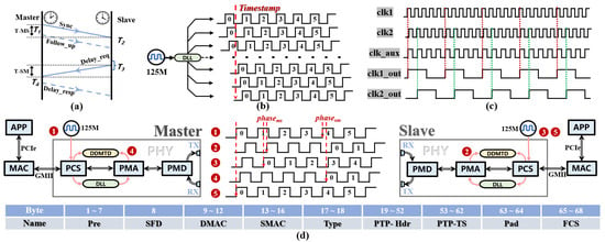
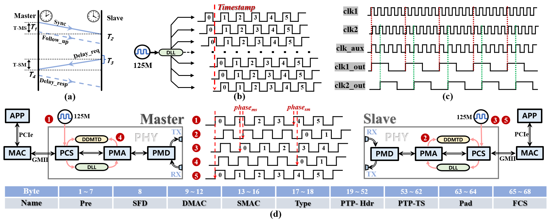
PTP is a clock synchronization protocol designed for distributed Ethernet systems, achieving synchronization through the periodic exchange of timestamped messages between master and slave clocks, as illustrated in Figure 1a. When the Sync message passes through the GMII between the MAC and physical (PHY) layers, the timestamp unit captures the current moment at the first bit after the Start-of-Frame Delimiter (SFD), and the PTP hardware clock latches the current time, recorded as timestamp T1. Subsequently, the Follow_Up message transmits the traced timestamp T1 to the slave clock. Upon receiving the Sync message, the slave clock records its local time T2. To avoid Sync message storms and the accumulation of constant phase errors, the slave clock randomly sends a Delay_Req message within a specific window and records the transmission time T3. When the master clock receives the Delay_Req message, it records T4 and sends it back to the slave clock via a Delay_Resp message. At this point, the slave clock has obtained four timestamps: T1, T2, T3, and T4. The PTP is based on the assumption of channel symmetry, i.e., that the forward and reverse transmission delays are equal. Under this assumption, the expressions for the path delay (delaysym) and clock offset (offsetsym) are as follows:
Figure 1.
The master-slave clock synchronization process of White Rabbit: (a) PTP timestamp message exchange. (b) A multiple vernier-based time-to-digital converter using a delay-locked loop. (c) Time difference measurement with DDMTD down-conversion when n = 5 (d) WR master-slave clock synchronization process.
2.2. Mathematical Model of WR Ranging
Distributed nodes in PTP operate in the asynchronous-clock mode, whereas WR works over Synchronous Ethernet. The network master node modulates the reference clock signal into physical-layer data streams and embeds and transmits the reference clock frequency by controlling the exact instant of each bit-level transition. PTP provides a timestamp resolution of 8 ns. In contrast, WR moves timestamp generation down to the boundary between the PCS and the Physical Medium Attachment (PMA) sublayer within the PHY layer. This location represents the timestamp sampling point in the parallel clock domain that is closest to the high-speed serial line rate of the physical medium.
The transmission timestamps T1 and T3 of the event messages are obtained using a multi-phase vernier time-to-digital converter based on a delay-locked loop (DLL), as shown in Figure 1b. The system uses a 125 MHz clock as a reference and employs the DLL to perform high-precision phase subdivision of a single clock cycle. In engineering practice, the clock cycle is typically subdivided into 64 uniformly spaced phase intervals. By using multi-phase clocks to capture the timestamps of trigger events in parallel, and based on the index of the phase channel that first detects a valid trigger edge along with the time interval corresponding to a single phase step, a time resolution of 0.125 ns is achieved.
The reception timestamps T2 and T4 are obtained by measuring the precise phase difference between the recovered receive clock and the local clock using the Digital Dual Mixer Time Difference (DDMTD) method, as shown in Figure 1c. Both the receive clock clk1 and the local clock clk2 have a frequency of approximately 125 MHz. The frequency of the auxiliary clock clkaux is set to N/(N + 1) times the frequency of the clock under test. Using clkaux to sample clk1 and clk2 yields clk1_out and clk2_out. The frequencies of both output clocks are reduced to 1/(N + 1) of their original frequencies, while their phase difference remains unchanged. In engineering practice, a down-conversion factor of 214 is typically chosen, achieving a time resolution of approximately 0.5 ps.
The phase relationship between the master and slave clocks is shown in Figure 1d. Red circled numbers ① ② ③ ④ and ⑤ represent clock generation locations and clock states. Clk1 A serves as the local clock of the master node and acts as the link reference clock, which is generated by frequency multiplication of the on-board crystal oscillator. Clk2 is the recovered receive clock output by the slave’s Clock and Data Recovery (CDR) circuit, which is essentially a copy of clk1 after experiencing the master-to-slave link delay delayms. Clk3 is the slave’s local clock. The clock offset offsetsym, calculated based on the link symmetry assumption, is used to set the initial operating point of the DDMTD. The phase difference between clk2 and clk3 is measured via DDMTD to obtain phasems, which is used to assist in generating the timestamp T2. Clk4 is the recovered receive clock output by the master’s CDR circuit, which is essentially a copy of clk3 after experiencing the slave-to-master link delay delaysm. The phase difference between the reference clk1 and clk4 is measured via DDMTD to obtain phasesm, which assists in generating the timestamp T4. After introducing link asymmetry correction, the slave’s local clock is adjusted again. Finally, the local clock clk3 at the slave node is disciplined to generate clk5, which achieves frequency and phase alignment with the reference clock clk1 for time synchronization.
The Ethernet message transmitted by WR is shown in Figure 1d. In byte-order sequence, it consists of a 7-byte preamble (Pre), a 1-byte Start-of-Frame Delimiter (SFD), a 4-byte destination MAC address (DMAC), a 4-byte source MAC address (SMAC), a 2-byte Ethernet Type field (Type), a 34-byte PTP header (PTP-Hdr), a 10-byte PTP timestamp (PTP-TS), a 2-byte pad field (Pad), and a 4-byte Frame Check Sequence (FCS).
Through DLL-based multi-phase interpolation and DDMTD, high-precision timestamps are obtained, denoted as T1p, T2p, T3p and T4p, respectively. The equation for the total loop delay is:
(T2p − T1p) + (T4p − T3p) = Δtxm + delayms + Δrxs + Δtxs + delaysm + Δrxm
In the equation, Δtxm and Δrxm are the transmit and receive hardware delays caused by the internal transmission circuits of the master side. Δtxs and Δrxs are the hardware delays of the slave side. The delay clock offset equation is:
(T2p − T1p) − (T4p − T3p) = Δtxm + delayms + Δrxs − Δtxs − delaysm − Δrxm − 2 ⋅ offset
The hardware delays are calibrated at the factory, read upon power-up after being written into the firmware, and subsequently affected by temperature, with real-time compensation applied using temperature variation coefficients. The asymmetry Δ of the bidirectional link is calibrated using the fiber swap method. Let the timestamps after swapping be denoted as T1p′, T2p′, T3p′, and T4p′. The link asymmetry based on the clock offset equation is:
Δ = delayms − delaysm = [(T2p − T1p) − (T4p − T3p)]/2 − [(T2p′ − T1p′) − (T4p′− T3p′)]/2
By substituting the asymmetry into Equations (3) and (4), the master-slave and slave-master link distances and time offsets can be obtained.
3. Experiment
3.1. Experiment on WR Ranging over a Point-to-Point Fiber Link
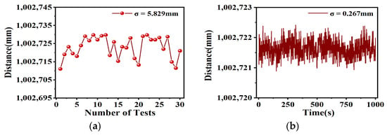
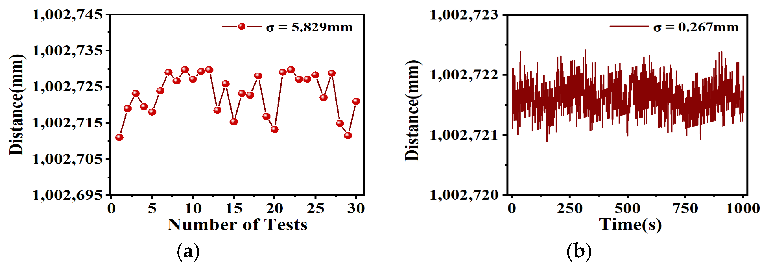
The intermediate precision of ranging after a power-cycle reboot is defined as follows: multiple power-cycle reboots are performed. A set of ranging measurements is acquired after each reboot. The mean value is calculated for each set of ranging data, and the one-sigma standard deviation is further computed over this batch of group-averaged values, which yields the intermediate precision of ranging after a power-cycle reboot. To evaluate the intermediate precision of ranging after power-cycle reboot for the point-to-point WR fiber-optic link, a 1 km single-mode dual-core bidirectional fiber is first used to connect the two ends of the devices. To maintain consistent variables with the subsequent free-space-link experiments, erbium-doped fiber amplifiers (EDFAs) of the same model are deployed for both bidirectional transmitting links. After the fiber-optic link is established, the power-cycle reboot is repeated 30 times. A one-minute measurement is performed after each reboot, and the distance measurements acquired within each one-minute interval are averaged. The test results are presented in Figure 2a. Under the condition of the 1 km fiber-optic link, the intermediate precision of ranging after a power-cycle reboot is 5.829 mm (1σ).
Figure 2.
1 km single-mode dual-fiber bidirectional fiber optic link: (a) intermediate precision of ranging under power-cycle reboot conditions. (b) ranging precision.
The ranging precision is defined as the one-sigma standard deviation of multiple independent ranging measurements obtained under a single power-on cycle, which characterizes the random dispersion of the measurements. To test the ranging precision of the system over the fiber-optic link, 1000 consecutive sampling points were collected under the same experimental conditions of the 1 km single-mode dual-fiber bidirectional fiber link. The test results are shown in Figure 2b, and the ranging precision is 0.267 mm.
3.2. Experiment on WR Ranging over a Point-to-Point Free-Space Optical Link
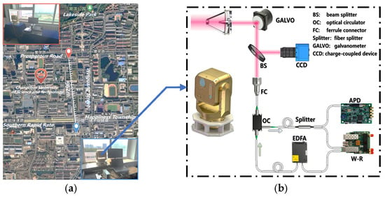
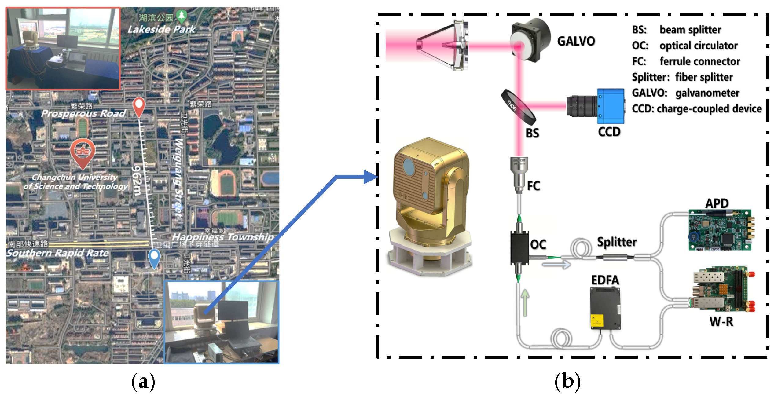
The experimental setup and transmission distance for the point-to-point free-space-link WR test are illustrated in Figure 3a, with a link length of approximately 1 km. The design of the near-ground laser-communication terminal is shown in Figure 3b. The terminal adopts a composite-tracking architecture combining coarse tracking and fine tracking. The coarse-tracking unit is a two-axis, two-gimbal, U-shaped turntable with a low-bandwidth control strategy, which realizes target acquisition and tracking over a large angular range. The fine-tracking unit employs a fast-steering mirror (FSM). Leveraging its characteristics of high bandwidth and small-angle response, it compensates for coarse-tracking residuals and suppresses high-frequency target disturbances. The system operates at a communication wavelength of 1550 nm and a beacon wavelength of 850 nm. A common-optical-path configuration is adopted, with an optical aperture of 70 mm. The beacon light and communication light are spatially separated by a wavelength beam splitter. Transmit-receive isolation within the fiber for the communication link is realized by a fiber circulator. The transmitted WR signal is power-amplified by an EDFA and connected to the transmit port of the fiber circulator. At the receive port of the fiber circulator, a 50:50 fiber coupler splits the received optical signal. One branch is used for WR communication reception, while the other branch is connected to an avalanche photodiode (APD) to detect the optical-intensity scintillation index of the link.
Figure 3.
White Rabbit experiment over a 1 km point-to-point free-space optical link: (a) Location of the experimental link. (b) Internal structure of the laser communication optical transceiver.
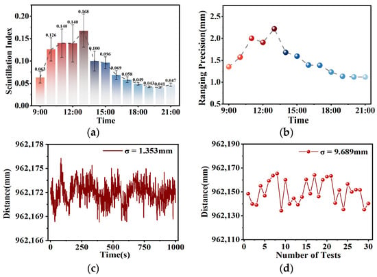
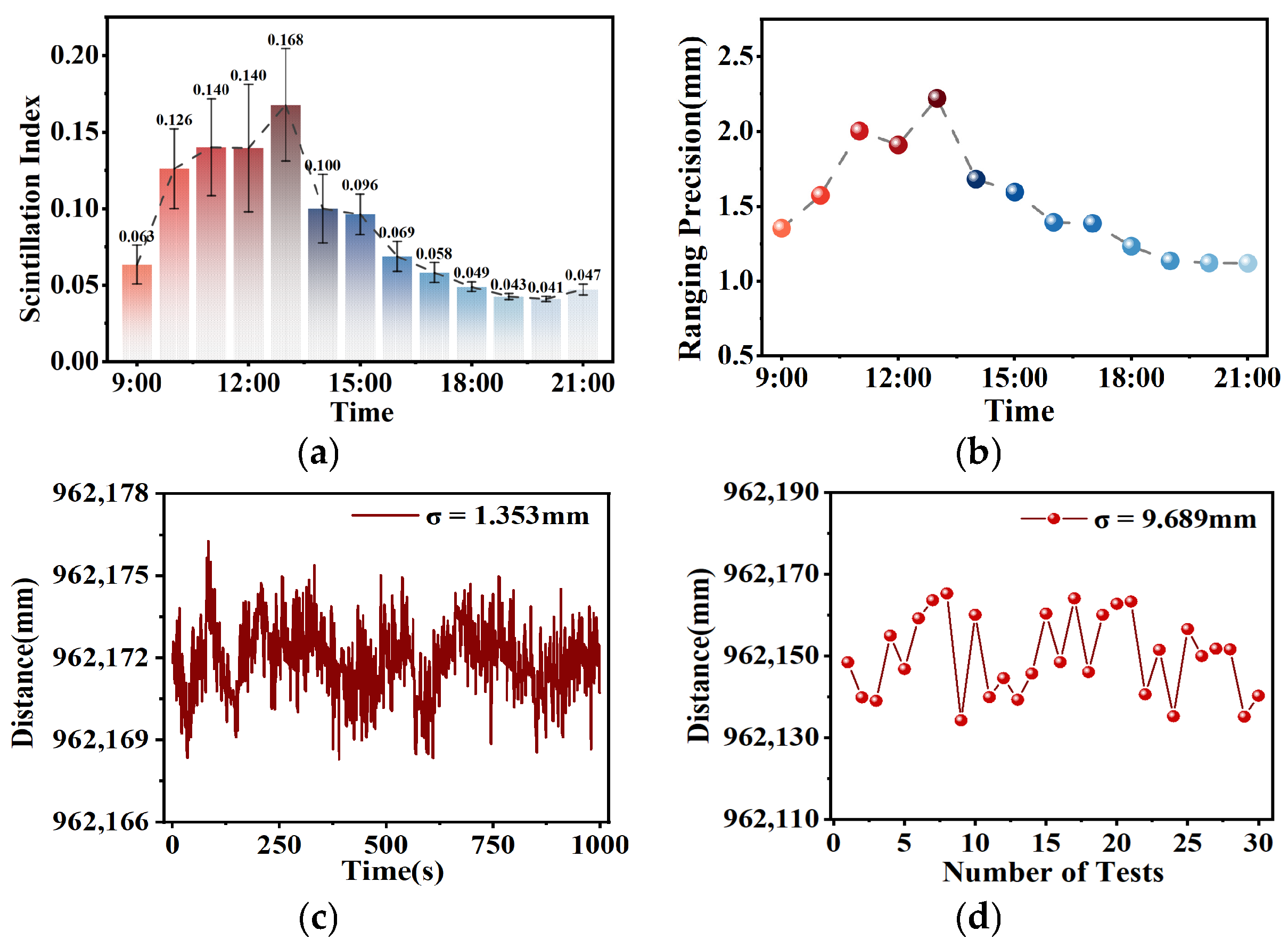
After the free-space link was established and stabilized, statistical recordings of the optical-intensity scintillation index induced by atmospheric turbulence and ranging results were performed every hour, starting at 9:00 a.m. on the same day. The experiment lasted until 21:00, for a total duration of 12 h. The statistical variation in the optical-intensity scintillation index over time is presented in Figure 4a. For the photodetector used to measure the received optical power under atmospheric turbulence at a 1550 nm wavelength, its maximum response rate is 2.5 Gbps. The serial line rate of the White Rabbit (WR) Ethernet is 1.25 Gbps. Under weak-turbulence conditions, the dominant energy of atmospheric optical-intensity fluctuations is concentrated within 0–150 Hz. Considering the above constraints comprehensively, an energy acquisition frequency of 1 kHz is adopted, with a 5 s sliding non-overlapping window. The scintillation index within each window is calculated as:
where I denotes the instantaneous received optical intensity, ⟨ ⟩ represents statistical averaging, ⟨I⟩ is the mean value of optical intensity, and ⟨I2⟩ stands for the mean square value of optical intensity. In Figure 4a, each scintillation index represents the mean value of scintillation indices obtained from 200 non-overlapping 5 s sliding windows starting at each integer hour, and the error bars denote one standard deviation of all scintillation-index samples. The maximum optical-intensity scintillation index of 0.167 occurred at 13:00, while the minimum value of 0.041 was observed at 20:00. The relationship between the scintillation index and the atmospheric refractive index structure constant is given by:
where k = 2π/λ, k is the wavenumber, λ is the wavelength, and L is the transmission distance. This formula is applicable when . Using Equation (6), the scintillation index of 0.041 corresponds to an atmospheric refractive index structure constant of , and the scintillation index of 0.168 corresponds to . According to the Davis turbulence classification standard, both fall under the category of moderate turbulence.
Figure 4.
Ranging results of the 1 km free-space link: (a) Statistics of optical intensity scintillation index over a 12 h period. (b) Statistics of ranging precision over a 12 h period. (c) Ranging precision at a scintillation index of 0.063. (d) Intermediate precision of ranging after power-cycle reboot at a scintillation index of 0.063.
According to historical weather records, the temperature was 25.3 °C, the wind speed was 4 km/h, with no rainfall and a visibility of 25 km at 13:00 on the test day. At 20:00, the temperature reached 23.7 °C, with a wind speed of 3 km/h, no rainfall, and visibility of 21 km. The statistical results of ranging precision variation versus time are shown in Figure 4b. In Figure 4b, each ranging-accuracy value is the mean of 1000 distance values output at 1 s intervals within approximately 16 min following each integer hour. During the experiment, as the scintillation index of the free-space link increased from 0.063 to 0.168, the ranging precision degraded from 1.353 mm to 2.221 mm.
4. Conclusions
To explore the transmission characteristics of WR over free-space optical links, this paper compares the intermediate precision of ranging after a power-cycle reboot and the ranging precision under a 1 km single-mode dual-core bidirectional fiber-optic link and a 1 km free-space optical link. The ranging precision and the atmospheric-turbulence-induced optical-intensity scintillation index are statistically analyzed for the free-space optical-link experiment from 9:00 to 21:00 on the test day. The experiments reveal that at an optical-intensity scintillation index of 0.063 for the free-space optical link, the intermediate precision of ranging after a power-cycle reboot degrades by approximately 1.66-fold, and the ranging precision degrades by approximately 5.07-fold compared with that of the fiber-optic link. In this 1 km free-space optical link experiment, it is observed that as the scintillation index increases from 0.063 to 0.168, the one-sigma standard deviation of ranging precision rises from 1.353 mm to 2.221 mm. The ranging performance of the free-space optical link is evidently inferior to that of the fiber-optic link. Compared with conventional laser-ranging techniques such as pulse-based laser ranging and phase-based laser ranging, WR is capable of performing both ranging and time synchronization, making it more suitable for networking among distributed nodes. Future research trends for WR may retain fiber-based wired transmission and synchronization for backbone networks while adopting flexible free-space optical synchronization at terminal nodes within certain regional ranges according to diverse application requirements.
Author Contributions
Conceptualization, X.Y.; validation, B.Z.; writing—original draft preparation, B.Z.; visualization, T.W.; project administration, P.L.; funding acquisition, S.T. All authors have read and agreed to the published version of the manuscript.
Funding
This work was supported by the National Natural Science Foundation of China (NSFC) Project under Grant 62231005.
Data Availability Statement
The data that support the findings of this study are available from the corresponding author upon reasonable request.
Conflicts of Interest
The authors declare no conflicts of interest.
References
- Margineanu, T.; Enescu, A.-M.; Enescu, H.-R.; Enachescu, M. NTP-synchronized time-stamper for RADAR signal acquisition. In 2024 IEEE International Black Sea Conference on Communications and Networking (BlackSeaCom); IEEE: New York, NY, USA, 2024; pp. 119–124. [Google Scholar]
- Garg, A.; Yadav, A.; Sikora, A.; Sairam, A.S. Wireless precision time protocol. IEEE Commun. Lett. 2018, 22, 812–815. [Google Scholar] [CrossRef] [Scilit]
- Lipiński, M. The inclusion of White Rabbit into the global industry standard IEEE 1588. In Proceedings of the 18th International Conference on Accelerator and Large Experimental Physics Control Systems, Online, 18–22 October 2021; JACoW: Geneva, Switzerland, 2022; pp. 126–131. [Google Scholar]
- Calvo, D.; Real, D.; Carrió, F. Sub-nanosecond synchronization node for high-energy astrophysics: The KM3NeT White Rabbit Node. Nucl. Instrum. Methods Phys. Res. A 2020, 958, 162777. [Google Scholar] [CrossRef] [Scilit]
- Yang, Z.; Ma, Y.; Yang, W.; Zhang, Y. Implementation of White Rabbit time synchronization system in state acquisition system of high-energy physics experimental device. J. Phys. Conf. Ser. 2022, 2264, 012014. [Google Scholar] [CrossRef] [Scilit]
- Liu, Y.; Ahmed, K.I.; Thotakura, N.L.; Yang, J.; Wu, Y.; Wang, H.; Sun, B.; Wang, W.; Zhang, Y.; Liu, Y. Enhancing time synchronization in smart grid with White Rabbit: Theory, architecture and challenges. IEEE Access 2025, 13, 146707–146721. [Google Scholar] [CrossRef] [Scilit]
- Macii, D.; Rinaldi, S. Time synchronization for smart grids applications: Requirements and uncertainty issues. IEEE Instrum. Meas. Mag. 2022, 25, 11–18. [Google Scholar] [CrossRef] [Scilit]
- Lopez-Jimenez, J.; Gutierrez-Rivas, J.L.; Marin-Lopez, E.; Rodriguez-Alvarez, M.; Diaz, J. Time as a service based on white rabbit for finance applications. IEEE Commun. Mag. 2020, 58, 60–66. [Google Scholar] [CrossRef] [Scilit]
- Girela-Lopez, F.; Ros, E.; Diaz, J. Precise network time monitoring: Picosecond-level packet timestamping for fintech networks. IEEE Access 2021, 9, 40274–40285. [Google Scholar] [CrossRef] [Scilit]
- Sakhnini, A.; Bourdoux, A.; Pollin, S. Estimation of array locations, orientations, timing offsets and target locations in bistatic radars. IEEE Trans. Radar Syst. 2023, 1, 520–531. [Google Scholar] [CrossRef] [Scilit]
- Alberto, M.; Simone, B.; Davide, C.; Cecilia, C.; Filippo, L.; Maurizio, M.; Sani, S.; Adalberto, S. Time and frequency dissemination for aerospace industry using the White Rabbit precision time protocol. In Proceedings of the 51st Annual Precise Time and Time Interval Systems and Applications Meeting, San Diego, CA, USA, 21–24 January 2020. [Google Scholar]
- Chishti, M.H.; Michev, R.; Yuan, T.; Waldschmidt, C. High precision synchronization for 77 GHz radar networks via White Rabbit. IEEE Trans. Radar Syst. 2026, 4, 897–910. [Google Scholar] [CrossRef] [Scilit]
- Kaur, N.; Frank, F.; Pinto, J.; Tuckey, P.; Pottie, P.-E. A 500-km cascaded white rabbit link for high-performance frequency dissemination. IEEE Trans. Ultrason. Ferroelectr. Freq. Control 2021, 69, 892–901. [Google Scholar] [CrossRef] [Scilit]
- Olaniya, M.P.; Sithamparanathan, K.; Panja, S. Time transfer within 100-ps uncertainty through 10-km long optical fibre link. In 2022 URSI Regional Conference on Radio Science (USRI-RCRS); IEEE: New York, NY, USA, 2022. [Google Scholar]
- Jamroży, M.; Gumiński, M.; Kasprowicz, G.; Romaniuk, R.; Poźniak, K. White Rabbit in space related application. In Photonics Applications in Astronomy, Communications, Industry, and High-Energy Physics Experiments 2015; SPIE: Bellingham, WA, USA, 2015; Volume 9662, p. 929002. [Google Scholar]
- Gilligan, J.E.; Konitzer, E.M.; Siman-Tov, E.; Zobel, J.W.; Adles, E.J. White Rabbit time and frequency transfer over wireless millimeter-wave carriers. IEEE Trans. Ultrason. Ferroelectr. Freq. Control 2020, 67, 1946–1952. [Google Scholar] [CrossRef] [Scilit]
- Seijo, Ó.; Val, I.; López-Fernández, J.A.; Montalban, J.; Iradier, E. On the use of White Rabbit for precise time transfer in 5G URLLC networks for factory automation applications. In 2019 IEEE International Conference on Industrial Cyber Physical Systems (ICPS); IEEE: New York, NY, USA, 2019. [Google Scholar]
- Zhou, X.; Hu, J.; Jiang, X.; Jin, D.; Yan, Z.; Zhang, L.; Song, C. Multi-channel data and clock transmission system based on free-space optical communication. J. Instrum. 2025, 20, T09001. [Google Scholar] [CrossRef] [Scilit]
- Zhang, P.; Guo, G.; Liu, K.; Zhou, W.; Hou, D. White Rabbit time synchronization over free space link with picosecond level. In 2025 Joint Conference of the European Frequency and Time Forum and IEEE International Frequency Control Symposium (EFTF/IFCS); IEEE: New York, NY, USA, 2025; pp. 1–2. [Google Scholar]
- Zhang, P.; Hou, D.; Liu, K.; Zhou, W.; Li, M.; Fang, L. Picosecond-level synchronization over optical free space link using white rabbit. Electronics 2025, 14, 970. [Google Scholar] [CrossRef] [Scilit]
- Ferraro, M.S.; Singh, A.; Murphy, J.L.; Dexter, J.L.; Zern, Z.T.; Mahon, R. White Rabbit time synchronization and data transfer for atmospheric free-space optical links. Opt. Eng. 2026, 65, 081803. [Google Scholar] [CrossRef] [Scilit]
- Girela-López, F.; Torres-González, F.; Díaz, J. Ultra-accurate Ethernet time-transfer with programmable carrier-frequency based on White Rabbit solution. In 2017 IEEE International Symposium on Precision Clock Synchronization for Measurement, Control, and Communication (ISPCS); IEEE: New York, NY, USA, 2017; pp. 1–6. [Google Scholar]
Disclaimer/Publisher’s Note: The statements, opinions and data contained in all publications are solely those of the individual author(s) and contributor(s) and not of MDPI and/or the editor(s). MDPI and/or the editor(s) disclaim responsibility for any injury to people or property resulting from any ideas, methods, instructions or products referred to in the content. |
© 2026 by the authors. Licensee MDPI, Basel, Switzerland. This article is an open access article distributed under the terms and conditions of the Creative Commons Attribution (CC BY) license.