


Abstract
Under continuous-wave laser irradiation, 7075 aluminum alloy is susceptible to melting and through-thickness penetration, while high-speed airflow may modify its thermal response and damage evolution. Bare and Cu–Ag–Zn-coated 7075 aluminum alloy targets were examined at airflow velocities of 510 and 1020 m/s using an 8 kW, 1080 nm laser with a 3 cm spot diameter. Melting onset and penetration breakdown were identified from image sequences sampled at 0.1 s intervals; back-surface temperature and transmitted-power measurements provided supporting evidence. For bare targets, the descriptive mean breakdown times were 1.97 and 1.95 s at 510 and 1020 m/s, respectively, compared with 4.13 s in a non-concurrent static reference study. The corresponding melting-onset times (1.03 and 1.05 s) were close to the static reference value of 1.17 s. For coated targets at 1020 m/s, three observed breakdown times (23.6, 50.0, and 51.2 s) yielded a descriptive mean of 41.6 s, approximately 21 times the bare-target mean of 1.95 s. A separate two-specimen subset (Batches 2 and 4), excluding the record associated with suspected coating damage of unverified origin, yielded a mean of 50.6 s (approximately 26 times); this subset ratio is not a stable performance metric. At 510 m/s, the three coated specimens showed neither visible melting nor penetration within their respective 30, 50, and 60 s observation windows, yielding right-censored bounds of >30, >50, and >60 s without an estimable arithmetic mean. In the two coated specimens with identifiable melting onset at 1020 m/s, melting was delayed by approximately 48.7 s relative to the bare-target mean, whereas the subsequent melting-to-breakdown intervals were 0.8–1.0 s. All comparisons are descriptive and limited to the tested conditions; neither velocity dependence nor the relative contributions of airflow-induced mechanisms can be established.
1. Introduction
Advances in laser technology have increased interest in laser-induced material damage [1]. During irradiation, materials absorb laser energy and undergo heating, potentially followed by melting, vaporization, and, under sufficiently severe conditions, structural failure. 7075 aluminum alloy is widely applied in aerospace structural components owing to its high specific strength and good formability [2]. Nevertheless, its resistance to high-power laser irradiation remains limited. Its mechanical behavior and microstructural evolution are sensitive to elevated temperatures [3], and through-holes may even occur under continuous laser irradiation [4]; the latter observation was made on 2A12 aluminum alloy. In certain operating environments, simultaneous exposure to high-speed airflow can further alter thermal responses and damage evolution.
High-speed airflow can influence laser-induced damage through competing processes. Convective heat transfer may remove energy from the irradiated region, whereas aerodynamic shear may displace molten material and expose underlying material to the incident beam. These processes may have opposing effects on damage progression, with their relative importance depending on the flow conditions [5,6,7,8,9,10,11,12].
Experimental and numerical studies have examined laser-induced damage under airflow, including the ablation of thin metal sheets, aluminum alloys, and C/SiC composites under tangential or supersonic flow, as well as plume shielding during laser–material interaction [5,6,7,8,9,10,11,12]. These studies have identified the competing possibilities of cooling and material removal, but have not fully quantified their relative contributions. For aluminum alloys, direct observational evidence is still lacking regarding whether airflow alters the heating-to-melting stage or the failure process after melting.
Protective coatings offer a potential means of improving resistance to laser-induced damage. They can be classified by their principal protective mechanisms into high-reflectivity/low-absorptivity, thermally insulating and ablation-resistant ceramic, and cermet composite systems [13,14,15,16,17,18,19,20,21,22]. Nevertheless, most evaluations are conducted under static or low-speed airflow conditions, and direct comparisons of coating performance under matched laser and high-speed airflow conditions remain limited. The coating used in the present study was previously evaluated under static conditions [23]. In those experiments, the reported breakdown time increased from 4.13 s for bare targets to 26.5 s for coated targets.
To assess the previously developed coating under combined laser irradiation and high-speed airflow, the present study examines two airflow velocities, 510 and 1020 m/s, with the earlier static results [23] serving as a non-concurrent reference. The comparative experiments were carried out under laser conditions and specimen geometry comparable to those in [23]. The experiments characterize the damage sequence of bare targets under airflow and compare bare and coated specimens tested under the same airflow and laser conditions.
The experiments were designed to explore whether the observed airflow-related and coating-related differences occur at different stages of damage evolution, rather than to establish a velocity-dependent relationship. The results suggest a stage-specific pattern: under the tested conditions, the airflow-condition observations show a shorter interval between melting onset and penetration, whereas the coating mainly delays melting onset. These observations are consistent with, but do not prove, the two effects acting on different stages; the two airflow conditions are discrete levels, not a velocity sweep.
2. Materials and Methods
2.1. Specimens and Materials
The substrate was 7075 aluminum alloy in the same material condition as that used in the previous static study [23]. Each specimen was a circular disk 110 mm in diameter and 3 mm thick, with a 2 mm chamfer at the front-surface edge. Two specimen types were examined: bare substrates and coated substrates. Bare specimens provided a reference for substrate damage under airflow, while coated specimens enabled descriptive comparisons of protection under the same airflow conditions. The specimen geometry is illustrated in Figure 1.
Figure 1.
Specimen geometry: (a) bare target; (b) laser-resistant-coated target.
2.2. Laser-Resistant Coating (Developed in Previous Work)
The coating used in this work is the same high-reflection Cu–Ag–Zn composite system developed in [23], deposited on the 7075 substrate by atmospheric plasma spraying with a nominal thickness of 50 µm. The coating specimens were produced in the same batch and using the same deposition procedure as those in [23]. The feedstock was prepared by vacuum induction melting of high-purity Cu, Ag and Zn at 1000 °C under argon, followed by inert-gas atomization at 0.5–2 MPa and sieving to 15–45 µm; the coating was deposited using a Praxair 5500 system and an SG100 gun on an ABB six-axis manipulator, with the arc current, gas composition, powder feed rate, standoff distance and substrate preheating optimized as described in [23]. The constituent roles were described in [23]: Cu provides high thermal conductivity and ductility, Ag contributes to high optical reflectivity (approximately 95% near 1080 nm was reported for the coating), and Zn was incorporated to modify the material properties. The precise constituent mass ratios and numerical spraying parameters are not reported for proprietary reasons. The coating formulation and deposition procedure were unchanged; airflow was the intended variable between campaigns, although the tests were non-concurrent and used different specimens (Section 2.6).
The coating specimens originated from the same production batch as those in [23]. Phase composition, bonding strength, and porosity were not independently characterized for the present specimens. For background information, the lamellar structure, interfacial bonding quality and crack resistance of thermally sprayed coatings directly affect their performance under thermal and mechanical loads [20,21]. However, the values of bonding strength and porosity reported in the above references do not refer to the coating used in this work. Within the present experimental design, the specified airflow condition was varied while the nominal specimen and laser parameters were held constant.
2.3. Laser and High-Speed Airflow Conditions
The experiments followed a controlled comparative design. Nominal laser parameters were matched to those of the earlier static tests [23], while airflow conditions were varied in the present campaign. A continuous fiber laser was used, with an output power of 8 kW, a spot diameter of 3 cm, an incident angle of 5°, an operating wavelength of 1080 nm, an output power stability of ±1.5%, and a beam parameter product (BPP) of approximately 1.5–2 mm·mrad. The laser beam irradiated the specimen surface through the observation window.
Two airflow velocities, 510 and 1020 m/s, were examined. In both cases, the nominal airflow direction was tangential to the specimen surface; the specimens were initially at room temperature, and the experiments used air as the working gas. These two conditions were discrete test points rather than a continuous velocity sweep. The available test records do not provide a complete characterization of the local flow field at the specimen, including its static pressure, density, total temperature, Mach number, and spatial uniformity. Accordingly, the stated velocities specify the two nominal test conditions but are insufficient to reconstruct the local convective heat-transfer or shear-stress distributions. No velocity-dependent damage law is inferred. The nominal laser settings, specimen geometry, and event-identification criteria were matched to the earlier static study [23], with the limitations of this non-concurrent comparison specified in Section 2.6.
2.4. Measurement System and Data Acquisition
As shown in Figure 2, the measurement system comprised a high-speed camera, a back-surface thermocouple, a transmitted-power meter, and auxiliary illumination. Images recorded at 0.1 s intervals were used to identify the first observable melting and penetration-opening events according to the criteria in Section 2.5. The thermocouple was mounted at the center of the back surface and measured the local temperature history rather than the peak front-surface temperature. The power meter monitored laser power transmitted through an opening and provided supporting evidence of penetration. Auxiliary illumination improved image contrast. The experimental sequence is shown in Figure 3.
Figure 2.
Schematic diagram of the experimental system layout. The layout is the same as that of the laser–airflow experimental platform reported in our recent work [24]; the schematic shown here was drawn independently for this work.
Figure 3.
Experimental procedure for laser irradiation tests under high-speed airflow.
The three measurement channels served distinct roles in event identification. Laser absorptivity and energy coupling may change with the surface condition during laser–metal interaction [25], while airflow and phase changes can affect reflection, absorption, and shielding [7,26]. Consequently, the image sequences were the primary basis for assigning melting-onset and penetration times. Back-surface temperature and transmitted-power records were used only as supporting evidence, because the three acquisition systems did not share a fully synchronized time base. Signal inflection points were therefore not used to assign event times. The back-surface thermocouple cannot establish the peak temperature at the irradiated front surface; neither the actual surface absorptivity nor the front-surface heat flux was measured.
2.5. Failure Criterion and Data Processing Conventions
Melting onset was defined as the time of the first frame showing a clearly identifiable continuous molten region within the irradiated zone. Penetration breakdown was defined by the first frame showing an opening through the specimen; an abrupt change in transmitted power was used only as supporting evidence. These criteria reflect the sequence of heating, melting, vaporization, and material removal that may occur during continuous laser irradiation [26]. Among them, vaporization, melt displacement and melt spattering are three coexisting removal mechanisms, and their relative proportions vary with power density and material state [27]. Transient heat transfer analysis of the thermal-melting process also provides a foundation for determining the melting onset time [28].
The first visible penetration opening typically appeared as a small dark region near the center of the molten zone; a step change in transmitted power provided supporting evidence. Melting onset was assigned to the first frame showing a continuous molten region. The authors applied these presence/absence criteria to the recorded frames, which were retained. Both event times were reported on the 0.1 s image-sampling grid without sub-frame interpolation. The sampling interval is approximately 5–10% of a 1–2 s event duration and about 0.2% of a 50 s duration; these ratios describe temporal resolution relative to event duration, not a formally estimated measurement uncertainty. Differences of 0.02 s between descriptive group means are therefore not interpreted as resolved experimental effects. The camera and thermocouple operated at 10 Hz, and the transmitted-power meter at 30 Hz; identical nominal sampling rates did not imply synchronization. A published reference solidus of 477 °C for 7075 aluminum alloy [29] was used only to contextualize back-surface readings, not as an event-detection threshold or an independently measured melting temperature of the specimens.
The following data-processing conventions were applied. (1) Individual observations and descriptive means are reported with the sample sizes used to calculate them; no inferential significance tests were performed with the available small samples. Individual event times are reported on the 0.1 s image grid. Additional decimal places in arithmetic means indicate calculation format, not finer measurement resolution. (2) A specimen without observed melting or penetration during its prescribed exposure window contributes a right-censored lower bound (for example, >30, >50, or >60 s), not an exact event time; these bounds were not entered into arithmetic event-time means. (3) In Group D, Batch 3 showed penetration at 23.6 s and local coating damage on post-test inspection. Because neither the origin nor the time of that damage was established, this observation was retained among the three recorded penetration events (23.6, 50.0, and 51.2 s; descriptive mean 41.6 s), while a separate two-specimen subset without the suspected anomaly (Batches 2 and 4; mean 50.6 s) was also reported. Batch 1, which showed no penetration by 30 s, was right-censored and was not included in either arithmetic mean. No independent melting-onset time was available for Batch 3. (4) Ratios of observed event times or descriptive means are descriptive comparisons, not estimates of statistical significance. (5) The earlier static data [23] are non-concurrent reference measurements obtained from separate specimens; comparisons with them cannot isolate an independent causal effect of airflow. By contrast, bare and coated targets at each tested airflow velocity were compared within the present experimental campaign.
2.6. Comparability with the Static Baseline [23]
The static reference values were taken from the earlier, non-concurrent study [23]. The reported substrate material condition, specimen geometry (7075 aluminum alloy, Ø110 × 3 mm disk, 2 mm chamfer), coating formulation and deposition procedure (the same coating production batch), nominal laser settings (8 kW, 1080 nm, 3 cm spot, 5° incidence), and definitions of melting and penetration were matched between campaigns. Nevertheless, the experiments took place at different times on separate specimens, and no concurrent static control was conducted in the present airflow apparatus. The intention to vary airflow does not establish that all unmeasured environmental or facility conditions were identical. Accordingly, static-to-airflow comparisons are descriptive context rather than controlled estimates of an airflow effect. The within-campaign comparisons between bare and coated targets at each specified airflow condition provide the more direct evidence of coating-associated differences, subject to the limited sample sizes and right-censored observations.
3. Results
3.1. Effect of High-Speed Airflow on Damage Behavior of Bare Targets
Bare-target laser irradiation tests were conducted at airflow velocities of 510 and 1020 m/s. Image sequences were the primary source for determining melting-onset and penetration-breakdown times. Figure 4 compares bare-target melting-onset and breakdown times under the two airflow conditions with the earlier static reference. The static values were reported previously [23] and were not measured during the present campaign. Direct comparison between the two datasets requires comparable laser settings, specimen geometry and failure criteria. Since the two campaigns were not concurrent and used separate specimens, the static values are only used for order-of-magnitude and trend references. The numerical difference between static and airflow conditions is therefore not used to rigorously estimate the independent causal effect of airflow.
Figure 4.
Comparison of observed melting-onset and penetration-breakdown times of bare 7075 aluminum alloy targets under the static baseline and high-speed airflow conditions. The static baseline values are taken from [23].
At 510 m/s (Group A, n = 3), the melting time of the three specimens was 1.1, 1.1 and 0.9 s, and the breakdown time was 2.0, 2.0 and 1.9 s, with descriptive means of 1.03 s and 1.97 s, respectively (Figure 4 and Figure 5). At 1020 m/s (Group C, n = 4), the melting time of the four specimens was 1.0, 1.0, 1.1 and 1.1 s, and the breakdown time was 1.8, 1.8, 2.2 and 2.1 s, with descriptive means of 1.05 s and 1.95 s, respectively (Figure 4 and Figure 6). Acquisition of the transmitted power failed during the 2nd test of this group; a fourth test was added to obtain another complete power record. Thus, the power panel shows Batches 1, 3, and 4, whereas the temperature panel includes all four batches.
Figure 5.
Morphology evolution of laser melting and penetration breakdown processes for three batches of bare targets under 510 m/s: (a) Batch 1 of Group A; (b) Batch 2 of Group A; (c) Batch 3 of Group A. Scale bars are 50 mm, derived from the 110 mm target diameter.
Figure 6.
Morphology evolution of laser melting and penetration breakdown for four batches of bare targets at 1020 m/s: (a) Batch 1; (b) Batch 2; (c) Batch 3; (d) Batch 4. The rows labelled Group A–D in the figure correspond to Batches 1–4 of Group C. The bright-white region marks the molten zone and the small dark spot at its center marks the penetration opening. The target diameter is 110 mm. Scale bars are 50 mm, derived from the 110 mm target diameter.
The descriptive comparison highlights two observations. First, breakdown times observed under airflow were shorter than the non-concurrent static value. The breakdown time of bare targets under the static baseline is 4.13 s [23], while it is approximately 2 s under both airflow conditions. The static breakdown time is about 2.10 and 2.12 times the values under airflow conditions at 510 m/s and 1020 m/s, respectively. Second, the observed melting-onset times differed comparatively little. The static baseline value is 1.17 s [23], while the values under the two airflow conditions are 1.03 s and 1.05 s. The differences among the three values are less than 0.15 s, close to the nominal frame interval of 0.1 s. The static melting time is only 1.14 and 1.11 times those under the two airflow conditions, respectively.
These observations suggest that the larger between-campaign difference occurs during the interval from melting onset to penetration breakdown, rather than before melting. The duration of this stage is quantified by the difference between breakdown time and melting time: 2.96 s under the static baseline [23], and 0.94 s and 0.90 s at 510 m/s and 1020 m/s, respectively. The observed interval under airflow was approximately one-third of the previously reported static interval, although the difference cannot be attributed solely to airflow. Changes in the thermal response and failure time of materials under airflow conditions have been reported in experimental and numerical studies of thin metal sheets [5,6], as well as in supersonic airflow ablation tests of composite materials [8]. The observations in this work are consistent with those reports.
Within the available temporal resolution, the results at 510 and 1020 m/s cannot be reliably distinguished. The difference in mean melting time is 0.02 s and the difference in mean breakdown time is 0.02 s, both far below the frame interval of 0.1 s. Accordingly, these differences are not used to infer velocity dependence. Establishing the velocity effect on damage behavior requires more test points at different airflow velocities. This issue is discussed further, together with the mechanism analysis, in Section 4.
3.2. Characteristics of Damage Process of Bare Targets
Section 3.1 reported the event times; this section examines the corresponding morphology sequences, back-surface temperature histories, and transmitted-power responses. The available image sequences document the transition from visible surface melting to penetration breakdown (Figure 5 and Figure 6). The corresponding back-surface temperature history and transmitted laser power response are shown in Figure 7 (510 m/s) and Figure 8 (1020 m/s).
Figure 7.
Back-surface temperature history and transmitted laser-power response of bare targets under 510 m/s: (a) back-surface temperature; (b) transmitted laser power. Both panels show Batches 1–3 of Group A.
Figure 8.
Back-surface temperature history and transmitted laser-power response of bare targets under 1020 m/s: (a) back-surface temperature, Batches 1–4; (b) transmitted laser power, Batches 1, 3 and 4. The transmitted-power record for Batch 2 was unavailable due to acquisition failure.
The image sequences show rapid formation and expansion of a molten region, followed by the appearance of a penetration opening. Combined with the results in Section 3.1, the observed melting-to-breakdown interval was approximately 0.9 s under both airflow conditions, compared with 2.96 s in the non-concurrent static reference [23]. One possible explanation is that airflow promotes molten-material removal and reduces transient shielding by the molten layer. This interpretation is consistent with, but not established by, the available temporal and morphological observations. It should be noted that the stripping rate of molten material was not measured in this work, nor was the molten layer thickness quantitatively characterized. The proposed interpretation rests on qualitative agreement between the observed time intervals and image sequences.
The temperature and transmitted-power records provide two complementary observations. First, while the central front surface is continuously irradiated until breakdown, the back-surface temperature rises continuously, yet perforation occurs before thermal perturbation fully penetrates through the thickness of the specimen. The input laser energy density is high, so the expansion of surface melting proceeds faster than heat conduction within the solid, and heat accumulates mainly near the irradiated surface. Second, the baseline of the power meter remains nearly constant during laser-off periods, indicating stable system operation throughout the recording period. The transmitted laser power exhibits a step change before and after breakdown, which is consistent with the direct transmission of laser through the specimen after the penetration opening forms, and provides independent supporting evidence for the image-based judgment.
Although changes in temperature and power provide supporting temporal context, the acquisition systems were not fully synchronized. Therefore, high-speed image sequences are uniformly adopted in this section as the basis for determining the instants of melting and breakdown, while temperature and power signals serve only as supporting evidence; their inflection points are not used as the precise failure instants. In addition, the back-surface thermocouple records the local back-surface temperature response, which is not equivalent to the peak temperature on the laser-irradiated front surface, and cannot be used to quantitatively separate the relative contributions of convective heat transfer and shear scouring induced by airflow.
3.3. Damage Behavior of Laser-Resistant-Coated Targets Under High-Speed Airflow
At 510 m/s, three coated specimens were irradiated for preset durations of 30, 50, and 60 s, with one specimen tested at each duration rather than repeated tests at a common duration. No visible melting or penetration breakdown occurred in any of the three windows, and no abrupt change in transmitted power was detected. The 30 s and 50 s specimens therefore provide lower bounds of >30 s and >50 s, respectively; the >60 s bound applies only to the specimen observed for 60 s. The resulting failure-time observations are right-censored; therefore, no mean failure time is reported (Figure 9 and Figure 10).
Figure 9.
Post-irradiation macroscopic morphology of laser-resistant-coated targets at 510 m/s: (a) 30 s; (b) 50 s; (c) 60 s (labelled First, Second and Third Experiment in the figure). Scale bars are 50 mm, taken from the ruler in each panel.
Figure 10.
Central back-surface temperature histories of laser-resistant-coated targets under 510 m/s. Batches 1–3 of Group B correspond to the 30, 50 and 60 s irradiation windows, respectively.
Post-test images (Figure 9) show a transition from pale yellow to white in the irradiated coating region and an expansion of the affected area with increasing exposure duration. This color change indicates modification of the coating in the irradiated zone, yet it alone cannot determine the specific phase transformation or compositional variation. The phase composition and microstructure of the irradiated coating were not characterized in this study.
The highest central back-surface temperature recorded in these tests was approximately 350 °C (Figure 10), below the adopted 477 °C reference solidus for 7075 aluminum alloy. Nevertheless, the back-surface temperature cannot directly determine the peak temperature on the laser-irradiated front surface or inside the coating. The differences in the slope of each temperature rise curve may reflect minor variations in the thermocouple attachment position and contact condition during specimen clamping. The reduced heating rate in the later heating stage and slight temperature drop in some records can be jointly explained by airflow heat dissipation and internal heat diffusion within the specimen. However, the back-surface temperature records alone cannot quantitatively distinguish their respective contributions.
At 1020 m/s, four coated-target tests were conducted with progressively extended irradiation windows (Group D, Batches 1–4; Figure 11 and Figure 12). Batch 1 was irradiated for a preset duration of 30 s and terminated without observed melting or breakdown. In Batch 2, melting features first appeared at 49.2 s and a penetration opening emerged at 50.0 s. Because auxiliary illumination was unavailable in the 49.2 s frame and the three systems were not fully synchronized, the image evidence for that instant is limited; temperature and transmitted-power records are consistent with, but cannot independently confirm, the estimate. The 49.2 s value should be regarded as an estimated observable melting instant rather than an independently cross-validated one. For Batch 4, melting occurred at 50.2 s and breakdown at 51.2 s. Batch 3 failed at 23.6 s, and local coating damage was found in the irradiated zone after the test; because the origin of this damage cannot be verified, the record is described as a suspected coating anomaly with an unverified origin. The failure is included in the mean of observed breakdown records but excluded from the two-specimen subset without the suspected anomaly. Three breakdown records are therefore available (23.6, 50.0 and 51.2 s), giving a complete-record descriptive mean of 41.6 s; the two specimens without the suspected anomaly (Batch 2 and Batch 4) give a subset mean of 50.6 s. Melting times are available only for Batch 2 and Batch 4 (49.2 and 50.2 s; mean 49.7 s), because Batch 3 has no independent melting time.
Figure 11.
Morphology evolution of laser-resistant-coated targets at 1020 m/s: (a) Batch 2; (b) Batch 3 (suspected coating anomaly with an unverified origin; retained in the complete-record mean but excluded from the subset); (c) Batch 4. The rows labelled Group A–C in the figure correspond to Batches 2, 3 and 4, respectively. Batch 1 is not shown because it was terminated at 30 s without failure. Scale bars are 50 mm, derived from the 110 mm target diameter.
Figure 12.
Central back-surface temperature histories of the four Group D tests at 1020 m/s. Curves are labelled Batches 1–4: Batch 1 ended after a 30 s observation window without breakdown; Batch 3 failed at 23.6 s and had suspected coating damage of unverified origin, but is retained in the complete-record breakdown mean. For Batches 2–4, the displayed records end at the image-based breakdown times (50.0, 23.6, and 51.2 s, respectively); post-breakdown thermocouple responses are not shown. All reported back-surface temperatures remain below the 477 °C solidus.
As shown in Figure 11, Batches 2 and 4 exhibit coating discoloration and expansion of the affected region, similar to the observations at 510 m/s. The back-surface temperature history (Figure 12) shows that specimens without the reported localized coating anomaly (Batches 1, 2, and 4) experience rapid temperature rise in the early stage and then tend to plateau, with a maximum back-surface temperature of approximately 350–420 °C. Batch 3, with the suspected local coating anomaly, heated up faster and failed at 23.6 s. This delay of the back-surface temperature rise is qualitatively consistent with the static numerical simulation of the same coating reported in [23], in which the coating reduced the substrate temperature rise relative to the bare target.
Thus, three observed breakdown times are available for Group D (Batch 2: 50.0 s; Batch 3: 23.6 s; Batch 4: 51.2 s), with a complete-record descriptive mean of 41.6 s. The two specimens without the suspected anomaly (Batch 2 and Batch 4) give a subset mean of 50.6 s; their melting times are 49.2 and 50.2 s (mean 49.7 s), whereas Batch 3 has no independent melting time. The breakdown range is 23.6–51.2 s for the complete set and 50.0–51.2 s for the subset; the melting range is 49.2–50.2 s for the subset. Batch 1 is retained as a right-censored non-failure observation (>30 s). The above values should be interpreted with the limited sample size. Notably, the intervals from melting onset to penetration breakdown in Batch 2 and Batch 4 are 0.8 s and 1.0 s, respectively, which are of the same order of magnitude as those of bare targets under airflow conditions (0.94 s at 510 m/s and 0.90 s at 1020 m/s). Under the static baseline, this interval is 2.1 s for coated targets and 2.96 s for bare targets [23].
3.4. Comparison of Coating Gain Under Identical Working Conditions
Section 3.1 and Section 3.3 report the event times for bare and coated targets under the respective airflow conditions. Here, the two target types are compared under matched test conditions to describe the observed increase in breakdown time associated with the coating. Figure 13 shows the intra-group comparison between coated targets and the static baseline, and Figure 14 presents the cross-comparison between bare targets and coated targets in terms of melting time and breakdown time. The corresponding individual observations and descriptive statistics are summarized in Table 1.
Figure 13.
Observed melting-onset and penetration-breakdown times of laser-resistant-coated 7075 aluminum alloy targets under static reference and high-speed airflow conditions. Gray solid bars represent the static reference values from [23], while blue hatched bars indicate right-censored observations at 510 m/s. Orange solid bars represent the observed means at 1020 m/s, whereas the orange hatched bar represents the two-specimen subset mean for penetration breakdown. At 510 m/s, the >60 s bar indicates the censoring limit of one specimen rather than an observed event; the other two specimens were censored at 30 and 50 s. At 1020 m/s, the mean penetration-breakdown time is 41.6 s (n = 3; 23.6, 50.0, and 51.2 s), while the two-specimen subset mean is 50.6 s (n = 2; Batches 2 and 4). The corresponding mean melting-onset time is 49.7 s (n = 2). Upward arrows indicate right censoring rather than observed melting or penetration-breakdown events.
Figure 14.
Comparison of observed melting-onset and penetration-breakdown times between bare targets and laser-resistant-coated targets under static and high-speed airflow conditions: (a) melting time; (b) breakdown time. The blue hatched bars represent right-censored observations for the coated targets at 510 m/s, rather than measured melting-onset or penetration-breakdown times. The bar drawn at 60 s for the 510 m/s coated case is the censoring limit, not a measured failure time; only the 60 s specimen supports >60 s, while the 30 s and 50 s specimens provide >30 and >50 s. For the 1020 m/s coated case, 41.6 s (breakdown, n = 3 complete records) is the complete-record mean, 50.6 s (breakdown, n = 2 subset) is the subset mean, and 49.7 s (melting, n = 2 subset) is the subset melting mean. The upward arrow indicates right censoring at 60 s rather than a measured failure time.
Table 1.
Summary of individual observations and descriptive statistics for all groups.
Under identical working conditions at 1020 m/s, the descriptive mean breakdown time of bare targets is 1.95 s (n = 4). The three coated breakdown records (23.6, 50.0 and 51.2 s) give a complete-record descriptive mean of 41.6 s (n = 3), approximately 21 times the bare-target mean. The two specimens without the suspected anomaly (Batch 2 and Batch 4) give a subset mean of 50.6 s (n = 2), approximately 26 times the bare-target mean. Ratios formed from the extreme observed failure times of the independent coated and bare specimens range from 10.7 to 28.4 for all observed coated failures, or from 22.7 to 28.4 for the two-specimen subset. These extrema are descriptive cross-sample combinations, not paired-specimen ratios. The 26-fold value is therefore a descriptive ratio based on the two-specimen subset, not a stable performance metric; the 21-fold value is the complete-record descriptive ratio. The longest single breakdown observation is 51.2 s (Batch 4). At 510 m/s, the descriptive mean breakdown time of bare targets is 1.97 s (n = 3); the coated targets survived their single 30, 50 and 60 s windows, providing only lower bounds (>30, >50 and >60 s). Because the 510 m/s coated result is a single right-censored observation, no exact multiple or percentage increase is reported.
Coated-target results can also be compared descriptively with the earlier static reference. At 1020 m/s, the complete-record mean of 41.6 s is approximately 1.6 times the static breakdown time of 26.5 s reported in [23], while the subset mean of 50.6 s is approximately 1.9 times. Because the static value is non-concurrent, these ratios are qualitative order-of-magnitude references, not causal estimates. The 510 m/s result is right-censored and based on single runs, so no exact ratio relative to the static baseline is reported.
Comparing melting-onset and breakdown times helps identify the stage at which the observed coating-associated delay occurs. At 1020 m/s, the descriptive means of melting time and breakdown time for bare targets are 1.05 s and 1.95 s, respectively. For coated targets, the melting mean is 49.7 s (subset, n = 2; Batch 3 has no independent melting time), the complete-record breakdown mean is 41.6 s (n = 3), and the subset breakdown mean is 50.6 s (n = 2). For the two specimens without the suspected anomaly, the coating delays melting onset by approximately 48.7 s. The interval from melting onset to penetration breakdown is 0.90 s for bare targets and 0.8 s and 1.0 s for coated targets. These values are of the same order of magnitude, and the coating does not introduce an order-of-magnitude change. Thus, for the two coated specimens with observable melting times, most of the measured delay occurred before melting rather than during the subsequent interval to breakdown.
All multiples reported in this section are ratios between individual observations and descriptive means under identical working conditions. They are used to characterize the magnitude of the observed temporal difference and do not constitute results of statistical inference. Calling the result an “average 26-fold improvement” would be misleading: approximately 26 is the two-specimen subset ratio, whereas the ratio calculated from all three observed coated failures is approximately 21. The effective sample sizes are 3 for the complete-record mean and 2 for the subset. The 510 m/s result can only be stated as a lower bound, and no exact multiple is reported. These results should be interpreted together with Table 1 in Section 3.5.
3.5. Summary of Results and Data Integrity
Table 1 summarizes all individual observations, the valid sample size of each group and the descriptive statistical results. Group A denotes bare target tests at 510 m/s, Group B denotes coated target tests at 510 m/s, Group C denotes bare target tests at 1020 m/s, and Group D denotes coated target tests at 1020 m/s. “Batch 1” to “Batch 4” within each group refer to each independent test run.
Several entries in Table 1 require the following qualifications. First, all three single-run tests of Group B (coated targets at 510 m/s) showed no failure within their preset windows. This group therefore provides only lower bounds (>30, >50 and >60 s, respectively); the >60 s bound applies only to the specimen observed for 60 s, and no group mean is reported. Second, among the four tests of Group D, Batch 1 is a non-failure observation within the 30 s window (>30 s) and is not included in the breakdown mean. Batch 3 failed at 23.6 s with local coating damage of unverified origin and is described as a suspected coating anomaly. It is retained in the complete-record breakdown mean (41.6 s, n = 3; 23.6, 50.0 and 51.2 s) but excluded from the subset of specimens without the suspected anomaly (Batch 2 and Batch 4; 50.6 s, n = 2). The melting mean of 49.7 s is based on Batch 2 and Batch 4 only, because Batch 3 has no independent melting time. Third, the transmitted power record of the 2nd test in Group C was lost; a supplementary fourth test provided another complete power record; the available power records are from Batches 1, 3, and 4. Fourth, the time bases of the three acquisition systems are not fully synchronized. All failure instants in this section are determined based on high-speed image sequences, and the nominal frame interval of 0.1 s constitutes the fundamental resolution limit for time judgment. Fifth, the back-surface thermocouple provides the local back-surface temperature response and cannot represent the peak temperature on the laser-irradiated front surface. In addition, convective heat transfer coefficient, wall shear stress, coating mass loss, and post-irradiation microstructure and interfacial damage were not independently measured in this work.
These qualifications define the scope within which the results can be interpreted. This work is a comparative test at two airflow velocities rather than a full velocity sweep. All temporal data are reported as descriptive statistics without inferential statistics. The relevant mechanism discussion and limitations are presented in Section 4.
4. Discussion
4.1. Airflow Mechanism: Competition Between Convective Cooling and Shear Scouring
At least three mechanisms may influence laser-induced damage under high-speed airflow: (H1) convective cooling, which removes heat from the irradiated zone and should delay both melting and breakdown; (H2) shear stripping of the molten layer, which removes the melt and weakens its transient shielding, and should shorten the interval after melting; and (H3) displacement of the ablation plume, which reduces plume shielding and increases the effective laser intensity reaching the surface, acting in the same direction as (H2). None of these quantities was measured in this work. The observations are therefore used only to test the qualitative predictions of these hypotheses, not to quantify them.
The observed breakdown times under airflow were shorter than those reported in the earlier, non-concurrent static study: 4.13 s for bare targets under the static baseline [23] and approximately 2 s under both airflow conditions. The static values are non-concurrent and serve only as references; the difference cannot be attributed strictly to the independent effect of airflow. In contrast, the influence on the melting time is limited: 1.17 s under the static baseline and 1.03/1.05 s under the two airflow conditions. The differences are less than 0.15 s, close to the nominal frame interval of 0.1 s. If airflow acted only through convective cooling, both melting onset and breakdown would be delayed; this is not observed. The evidence alone cannot determine the relative magnitude of the two effects, but it indicates that the heating-to-melting stage is less sensitive to airflow than the post-melting failure stage within the 0.1 s resolution.
This pattern is compatible with a limited net effect on the observed melting-onset time and potential contributions from H2 and/or H3, although it cannot establish their relative magnitudes: the melting time changes little (1.17 → 1.03/1.05 s), whereas the melting-to-breakdown interval falls from 2.96 s to 0.90–0.94 s. If convective cooling dominated, both instants would be delayed; this is not observed. If shear stripping and/or plume displacement are the main post-melting mechanisms, the post-melting interval should shorten while the pre-melting stage remains nearly unchanged; this is what is observed. The melt-layer thickness, stripping rate, plume attenuation, convective heat-transfer coefficient and wall shear stress were not measured, however, so the relative contributions of H2 and H3 cannot be separated, and the relative contributions of H1, H2 and H3 cannot be quantified. The data are compatible with this stage separation; they do not prove it.
The observed interval from melting onset to penetration breakdown differs between the campaigns, decreasing from 2.96 s under the static baseline [23] to 0.94 s (510 m/s) and 0.90 s (1020 m/s) under airflow conditions, roughly one-third of the original value. Temporal data alone can only show that the duration of this stage is altered, but cannot identify its cause. One interpretation consistent with the above observations is that the removal process of the molten layer is accelerated. Relevant mechanistic considerations are summarized below. During continuous laser ablation of aluminum targets under supersonic airflow, gas-phase oxidation participates in and modifies the surface state and material removal behavior [7]. Under tangential airflow, the shielding degree of plumes and near-surface species on laser–material coupling also varies with airflow conditions [12]. For the combination of continuous laser and metal investigated in this work, after surface melting occurs, the laser absorptivity of the metal generally rises with increasing temperature and oxidation, accompanied by enhanced energy coupling [25]. Meanwhile, the melt and the plume exert certain attenuation and scattering effects on the incident laser [12]. Under static conditions, molten material may partially reside in the irradiated zone and maintain transient shielding. According to the above interpretation, stripping of molten material by airflow weakens this shielding, enabling subsequent failure to occur within a shorter time. However, none of these processes were measured in this work. From the perspective of energy coupling pathways, the transition from conduction mode to keyhole mode in laser–metal interaction indicates that changes in surface morphology and state can reverse the coupling regime [30]. In terms of removal modes, vaporization, melt displacement and melt spattering are three coexisting mechanisms under continuous laser irradiation, and their relative proportions vary with power density and material state [27]. Explosive phase removal may also occur under extreme conditions [26]. Together, these mechanisms provide a physically plausible interpretation of the temporal and morphological observations. However, this mechanistic context comes from the literature rather than direct measurements in the present tests and therefore does not validate the proposed explanation.
The ablation plume represents another possible influence. The plume absorbs and scatters part of the incident laser, so blowing it downstream can increase the effective intensity at the surface and enlarge the damage [7,12]. This acts in the same direction as shear stripping and cannot be separated from it with the present data.
Nevertheless, the molten layer thickness and removal rate, convective heat transfer coefficient, wall shear stress, actual surface absorptivity and plume characteristics were not measured in this work. Consequently, the event-time data are compatible with these mechanisms but cannot independently verify any of them. This section only shows that the available observations are not contradictory to this interpretation; it cannot determine which effect is dominant between convective cooling and shear scouring, nor provide their quantitative ratio. Notably, both the sequence “melting onset—molten zone expansion—penetration opening formation” recorded in the morphological sequences in Section 3.2 and the phenomenon that perforation occurs before thermal perturbation fully penetrates the specimen thickness are consistent with the judgment that heat accumulates mainly near the irradiated surface. This judgment, however, is also built upon qualitative evidence.
The observed time differences between 510 and 1020 m/s are below the available temporal resolution. The difference in mean melting time is 0.02 s and the difference in mean breakdown time is 0.02 s, both far below the frame interval of 0.1 s. At higher airflow velocity, both convective heat dissipation and shear stripping would be expected to increase, and these two exert opposite effects on failure time. Without independent measurement of these two effects, their net effect cannot be distinguished from only two velocity points. Therefore, this work does not establish a velocity dependence relationship and does not extrapolate conclusions beyond the tested velocity range. The magnitude of airflow effects reported in the literature varies greatly for other material systems (for example, a numerical study on ablation of C/C composites under high-speed airflow in [11] shows that airflow may only slightly increase the ablation rate). This also indicates that the magnitude of temporal variation observed in this work should not be regarded as a universal rule transferable across different material systems.
In summary, the airflow-condition tests exhibit shorter post-melting intervals than the non-concurrent static reference, whereas differences in melting-onset time are close to the measurement resolution; this comparison alone does not establish an independent airflow effect. This stage-based comparison provides context for the discussion of coating performance below. If the coating mainly contributes during the pre-melting heating stage, then under identical airflow conditions, the “melting onset—penetration breakdown” interval of coated targets should be of the same order of magnitude as that of bare targets, and the gain should mainly manifest as delayed melting onset.
4.2. Protective Performance and Degradation of the Coating Under High-Speed Airflow
Section 3.3 and Section 3.4 present the performance of coated targets under the two airflow conditions. At 510 m/s, no melting or penetration breakdown was observed for coated targets across the single 30, 50 and 60 s runs; the >60 s lower bound applies only to the specimen observed for 60 s, and no group mean is reported. At 1020 m/s, three breakdown records were obtained (23.6, 50.0 and 51.2 s), with a complete-record descriptive mean of 41.6 s; the two specimens without the suspected anomaly (Batch 2 and Batch 4) give a subset mean of 50.6 s, and their melting mean is 49.7 s. Compared with bare targets under identical working conditions, the coated breakdown time increased from approximately 2 s to 41.6 s (complete-record mean) or 50.6 s (subset mean), while at 510 m/s only lower bounds are available. This section discusses the origin of this gain, the evidence related to coating degradation, and its limitations.
Regarding the observed protection gain, Section 3.4 indicates that the associated delay differs between stages of the damage process. Under 1020 m/s, the observed mean melting-onset time is 49.7 s for the coated subset, compared with 1.05 s for bare targets, corresponding to a delay of approximately 48.7 s. Meanwhile, the interval from melting onset to penetration breakdown is 0.90 s for bare targets and 0.8 s and 1.0 s for coated targets, falling within the same order of magnitude. For the two specimens with identifiable melting onset, the coating-associated delay occurred predominantly during the pre-melting stage. Once surface melting occurs, the subsequent failure process still completes on a timescale comparable to that of bare targets. This stage-specific observation is consistent with the qualitative interpretation discussed in Section 4.1. However, the separate experimental campaigns and unmeasured physical processes prevent a definitive attribution of either stage to a particular airflow mechanism.
Two possible pathways may contribute to the observed delay in melting onset: reducing surface absorption of incident laser radiation (H4) and delaying heat transfer toward the substrate (H5). No thermal-resistance or energy-balance calculation was performed in this work; although a 50 µm coating might be expected to provide limited thermal insulation relative to the 3 mm substrate, the relative contributions of reduced absorption (H4) and altered heat transfer (H5) remain undetermined. This remains an inference: the reflectivity, absorptivity, thermal conductivity and surface heat flux of the coating were not measured, so the two pathways cannot be separated and the conclusion is not quantified. The static simulation in [23] used an absorptivity of 5% at 1080 nm for the coating, compared with 25% for the bare alloy; this is a model input rather than a measurement, but it is consistent with the high reflectivity of the coating. Accordingly, the observed coating effect is described as a delay in melting onset without assigning it to a single mechanism. This interpretation is built upon the two specimens without the suspected anomaly at 1020 m/s and the bare-target controls. It is a provisional explanation consistent with the present data and does not constitute full proof of the coating failure mechanism; dedicated characterization work is still required to clarify the protective mechanism of this coating.
Regarding coating degradation, post-test images show a pale-yellow-to-white color change and expansion of the affected region with increasing irradiation duration (Figure 9 and Figure 11). This color change indicates modification of the coating within the irradiated zone. Nevertheless, the phase composition and microstructure of the post-irradiation coating were not characterized, so the specific phase transformation or compositional variation cannot be identified. Failures of thermally sprayed ceramic and composite coatings under laser and high-temperature environments commonly involve interlayer cracking and spalling, oxidation-dominated ablation, and degradation of bonding between coating and metallic substrate [16,17,18,19]. The layered structure and interfacial bonding quality of coatings directly affect their cracking resistance [20,21]. For thermal barrier coating systems, spallation, erosion and oxidation are also generally recognized as typical failure modes [22]. These literature findings provide background for understanding potential degradation pathways of the coating in this work. However, coating mass loss, microcracks or interfacial debonding were not measured in this work, so these failure modes can only be mentioned as possible contributing factors rather than reported observations of this work.
The post-test images at 510 m/s (Figure 9) and 1020 m/s (Figure 11) show a similar qualitative pattern: a pale-yellow-to-white color change and an expanding affected region. The macrographs do not establish a velocity-dependent degradation mode; the apparent difference in protection time between the two conditions remains an observation, not a validated mechanism, and discriminating it would require mass-loss, crack-density and interfacial-bonding measurements.
Coated-target back-surface temperature histories provide supporting context for the observed failure times. For specimens without the suspected anomaly, the maximum central back-surface temperature was approximately 350 °C in the three tests at 510 m/s and approximately 350–420 °C at 1020 m/s, both lower than the adopted reference melting onset temperature of 477 °C for 7075 aluminum alloy. The back-surface thermocouple records the local back-surface response and cannot represent the peak temperature on the laser-irradiated front surface or inside the coating. Thus, the measured back-surface location remained below the adopted substrate solidus during the recorded observation periods. It is insufficient to back-calculate the front-surface temperature level or quantitatively compare thermal loads at the two velocities.
Although the observations differ between the airflow conditions, the small sample sizes, unequal observation windows, and right-censored records do not support a velocity-dependent trend. At 510 m/s, three coated specimens survived their preset 30, 50 and 60 s windows; at 1020 m/s, breakdown was observed in some specimens, but one specimen had a suspected local coating anomaly whose origin cannot be verified. Because the two conditions differ in observation window and outcome type, and because the 510 m/s result is right-censored, the present data are insufficient to determine whether the coating protection time decreases with increasing airflow velocity. No physical mechanism can be attributed to such a trend from these observations.
Comparisons with the earlier static coated-target results require caution. At 1020 m/s, the complete-record mean of 41.6 s is approximately 1.6 times the static coated-target breakdown time of 26.5 s reported in [23], while the subset mean of 50.6 s is approximately 1.9 times. These ratios are qualitative references because the static data are non-concurrent and were obtained with separate specimens. For bare targets, the airflow breakdown time is roughly half the static value. This difference is consistent with, but does not prove, different response patterns for bare and coated targets across the non-concurrent campaigns. For bare targets, shear stripping may shorten failure; for coated targets, airflow-induced cooling may partially offset surface-layer degradation. The comparison cannot be converted into an exact proportional relationship, and the single right-censored 510 m/s result prevents a direct comparison with the static baseline.
Batch 3 of Group D failed at 23.6 s with local coating damage. Because the origin of this damage cannot be verified, the record is described as a suspected coating anomaly with an unverified origin. The failure is included in the mean of observed breakdown records but excluded from the two-specimen subset without the suspected anomaly. This observation indicates substantial variability in the breakdown time; however, the contribution of the post-test coating damage cannot be established because its origin and occurrence time remain unknown.
Finally, coating performance may depend on thickness, surface condition, and fabrication quality. Only one coating formulation and one nominal thickness were adopted in this work, and comparative tests on thickness or process parameters were not carried out. Hence, the relationship between protective performance and coating parameters cannot be established, and the observed magnitude of time extension should not be regarded as an intrinsic performance metric of this type of coating.
4.3. Qualitative Comparison with Coating Systems Reported in the Literature
To contextualize the findings, Table 2 summarizes the principal mechanisms and reported limitations of three classes of protective coatings, together with the system examined here. The three categories are high-reflectivity/low-absorptivity coatings [13,14,15], ceramic thermal-insulating and ablation-resistant coatings [16,17,18,22], and cermet composite coatings [19,20,21].
Table 2.
Qualitative comparison of representative protective coating systems reported in the literature.
The mechanisms and drawbacks of the three categories can be summarized as follows. High-reflectivity/low-absorptivity coatings reduce laser energy entering the material by lowering surface absorption. Their effectiveness largely depends on reflectivity and its retention capability under heating. Thermal accumulation and interfacial integrity under prolonged irradiation are the main limiting factors [13,14,15]. Ceramic thermal-insulating coatings delay heat transfer to the substrate by virtue of low thermal conductivity and possess certain ablation resistance. Nevertheless, their intrinsic brittleness, thermal expansion mismatch with metallic substrates, and susceptibility to cracking and spalling under airflow shear and thermal cycling are common problems [16,17,18,22]. Cermet composite coatings combine metal-phase toughening and ceramic-phase heat resistance to achieve both thermal insulation and erosion resistance. Their overall performance still relies on the control of layered microstructure and interfacial bonding [19,20,21].
Importantly, this comparison is qualitative. Substrate materials, coating structure and thickness, laser parameters, airflow conditions and failure criteria differ across references. Some coating evaluations were conducted under static or low-speed conditions, and some studies adopted non-metallic substrates including C/SiC and C/C. Accordingly, Table 2 only illustrates general differences in the mechanisms and drawbacks among different technical approaches. It does not represent a performance ranking under identical conditions, nor can it support the conclusion that “the coating in this work outperforms a certain system”. The protection durations reported for different systems are therefore not listed for quantitative ranking. The temporal gain observed for the coating in this work (from approximately 2 s to a complete-record mean of 41.6 s, with a subset mean of 50.6 s, at 1020 m/s; only lower bounds >30/>50/>60 s at 510 m/s) is obtained under specific laser, specimen and airflow conditions, and cannot be directly transferred to other coating systems or test conditions.
Unlike evaluations conducted without substantial airflow, the present tests expose the coating to simultaneous laser irradiation and high-speed gas flow, potentially involving both convective heat transfer and aerodynamic removal. Previous investigations on sprayed ceramic and composite coatings provide fundamental understanding of coating damage and failure under laser and high-temperature exposure [16,17,18]. However, their test conditions differ from those of this work, so direct side-by-side comparison is inappropriate. The observations in this work reveal that the temporal gain of the coating under airflow corresponds to the characteristic of “delayed melting onset”. This provides a quantifiable starting point for coating evaluation under aerodynamic environments, namely using melting time and breakdown time as two separate indicators to characterize coating contribution. Nevertheless, further experiments over a wider range of flow velocities and laser powers are required before this phenomenon can be developed into a design basis.
4.4. Engineering Significance and Applicable Boundaries
Under the conditions investigated, bare 7075 aluminum alloy underwent penetration breakdown in approximately 2 s under high-speed airflow (the descriptive means are 1.97 s and 1.95 s at the two velocities, with sample sizes of 3 and 4, respectively). After applying the previously developed laser-resistant coating, the complete-record descriptive mean breakdown time is 41.6 s at 1020 m/s (n = 3; 23.6, 50.0 and 51.2 s), and the subset mean for the two specimens without the suspected anomaly is 50.6 s (n = 2; maximum single observation 51.2 s). At 510 m/s, no melting or penetration breakdown was detected within the single 30, 50 and 60 s windows; only the 60 s specimen supports >60 s. Combined with the static coating results reported in [23], the protective potential of such coatings under airflow environments can be quantified: under the conditions tested herein, the effective protection time increases from the order of seconds to tens of seconds, and this improvement mainly originates from the delay in substrate melting onset.
These results provide experimental evidence relevant to evaluating laser-protective coatings under high-speed airflow. On the one hand, the “identical working conditions” test methodology establishes a quantitative framework for coating gain with airflow incorporated: melting time and breakdown time are used separately to characterize coating contribution, distinguishing between two possible modes of action: “delaying melting onset” and “altering post-melting failure process”. On the other hand, identifying the coating gain as “delayed melting onset” offers a testable hypothesis for subsequent coating development and assessment under aerodynamic environments.
The findings do not support service-life predictions or operating-duration recommendations for specific engineering systems, for three reasons. First, tests were only carried out at two airflow velocities of 510 m/s and 1020 m/s without continuous velocity sweeping. Second, the sample size is limited (3–4 batches for bare targets; three breakdown records for coated targets, of which two specimens without the suspected anomaly contribute to the subset mean; the 510 m/s result is a single right-censored observation). Third, governing parameters including peak surface temperature, surface heat flux, convective heat transfer coefficient and wall shear stress were not measured. Therefore, the above statement of engineering significance is restricted to “experimental evidence obtained under the tested laser, coating, specimen and airflow conditions”.
4.5. Limitations and Uncertainties
This section identifies the principal limitations and explains their implications for interpreting the results.
Test conditions and sample size: The number of completed tests was limited. Only two airflow velocities (510 m/s and 1020 m/s) were selected, forming a comparative test at two discrete levels rather than a velocity sweep. Consequently, velocity dependence cannot be established and fitted trends cannot be obtained. The difference in mean temporal observations between the two velocities (0.02 s) is below the 0.1 s frame interval and does not constitute a resolvable difference. In terms of sample size, each group contains 3–4 batches. Three breakdown records are available for Group D; two specimens without the suspected anomaly contribute to the subset mean. Sample sizes of n = 2 to 4 do not support inferential statistics; hence, only individual observations and descriptive means are reported in this work. Because of constraints on the test facility, specimen supply and test schedule, several additional experiments could not be completed in the present campaign: additional airflow velocities, a fuller flow-field characterization (Mach number, total temperature and flow-generation details), repeat tests at 510 and 1020 m/s, a static control on the airflow apparatus, a higher frame rate, front-surface infrared thermography, and further coating characterization (phase composition, bonding strength, porosity). These measurements are priorities for future work.
Data integrity: All three single-run tests in Group B (coated targets at 510 m/s) survived their preset windows; the >60 s bound applies only to the specimen observed for 60 s, while the 30 s and 50 s specimens provide >30 s and >50 s lower bounds. These right-censored observations are excluded from arithmetic averaging. In addition, the transmitted power acquisition failed for the 2nd test of Group C, and an additional fourth test was conducted to obtain a complete power record. These circumstances mean the number of failure instants available for precise comparison in Table 1 is less than the total number of test batches. The main comparative conclusions of this work are therefore built upon a small number of measurable observations.
Measurement capability: All failure instants in Section 3 and Section 4 are determined from high-speed image sequences. The nominal frame interval of 0.1 s sets the fundamental temporal resolution limit; time differences smaller than this magnitude cannot be distinguished in this work. The time bases of the three acquisition systems are not fully synchronized. Temperature and transmitted power signals serve only as auxiliary evidence, and their inflection points are not used to define failure instants. Furthermore, the back-surface thermocouple captures the local temperature response at the central back surface of the specimen, which is not equivalent to the peak temperature on the laser-irradiated front surface and cannot directly reflect the temperature level inside the coating. The camera and thermocouple were operated at 10 Hz and the power meter at 30 Hz; higher frame rates and non-imaging criteria were not available. No front-surface temperature field (for example, infrared thermography) was measured, and the airflow total temperature, Mach number and flow-generation details are not reported here. These missing measurements constrain the interpretation of the aerodynamic conditions and remain priorities for future work. No static control was run on the airflow apparatus. Our own simulations of laser ablation with a transverse flow cover a lower power and velocity range and are therefore not used for quantitative validation. A simulation at the present experimental conditions, with measured absorptivity and surface temperature, could not be completed within the revision period because of the same constraints. Accordingly, no quantitative simulation-based validation is claimed. A formal inter-rater analysis was not performed; the criteria are binary and the frame records are retained.
Unmeasured physical quantities: This work did not measure peak surface temperature and surface heat flux on the laser-irradiated surface, actual absorptivity of the surface to incident laser, convective heat transfer coefficient, wall shear stress, coating mass loss, microcracks or interfacial debonding. Therefore, the relative contributions of convective cooling and aerodynamic shear scouring cannot be quantitatively decomposed, and the observed temporal variations cannot be attributed to a definite mechanism. Correspondingly, the mechanism discussions in Section 4.1 and Section 4.2 should be interpreted as explanations consistent with observations rather than independently quantified mechanisms.
Coating characterization: The laser-resistant coating adopted in this work was developed previously (nominal thickness 50 µm; its system, constituents and process are summarized in Section 2.2, and the deposition procedure is described in [23]; the exact mass ratio is not disclosed). No basic characterization of the coating, including phase composition, bonding strength and porosity, was performed in this work, nor were comparative tests on coating thickness or process parameters conducted. This means that this work can only report whether this coating formulation works or fails under specific conditions. It cannot establish the relationship between protective performance and coating parameters, nor determine the performance ceiling of this formulation.
Finally, cross-study comparisons remain subject to important limitations. Different materials and coating systems exhibit highly variable performance under airflow conditions (a numerical study on C/C composite ablation under high-speed airflow in [11] shows that airflow may only slightly increase the ablation rate). The reported protection thresholds of different coating systems are not directly comparable [14]. This indicates that the large temporal variation observed in this work should not be regarded as a universal rule transferable across different material systems, and the qualitative comparison in Section 4.3 cannot replace controlled tests under identical conditions. To extend these conclusions beyond the tested operating conditions, supplementary experiments over wider velocity and power ranges and independent measurements of the above unquantified physical variables are required. Subject to test schedule and funding, additional tests covering more combinations of airflow velocity and laser power should be performed to further verify the protective performance and applicable scope of the coating under diverse working conditions.
5. Conclusions
Building on the earlier static investigation [23], this study reports laser-induced damage observations for bare and Cu–Ag–Zn-coated 7075 aluminum alloy specimens under two nominal tangential airflow velocities, 510 and 1020 m/s. Melting onset and penetration were identified primarily from image sequences sampled at 0.1 s intervals; back-surface temperature and transmitted-power signals supplied supporting evidence. The conclusions below describe the specified specimens, laser conditions, and airflow test points rather than a general velocity-dependent damage law:
- (1)
- Bare targets showed descriptive mean penetration times of 1.97 s (n = 3) at 510 m/s and 1.95 s (n = 4) at 1020 m/s, with corresponding mean melting-onset times of 1.03 and 1.05 s. The earlier non-concurrent static study [23] reported 4.13 s for penetration and 1.17 s for melting onset. The observed melting-to-penetration intervals were approximately 0.94 and 0.90 s under the two airflow conditions, versus 2.96 s in the static reference. These cross-campaign differences are descriptive and cannot be attributed exclusively to airflow in the absence of a concurrent static control.
- (2)
- The shorter observed post-melting intervals relative to the historical static reference are compatible with hypotheses involving molten-layer removal and/or plume displacement, but these processes were not measured independently. Convective heat transfer, aerodynamic shear, melt-layer thickness, material removal rates, and plume attenuation were not quantified. The 0.02 s differences between the two airflow-condition means are smaller than the 0.1 s image-sampling interval and do not establish a resolvable trend with airflow velocity or identify a dominant mechanism.
- (3)
- At 1020 m/s, coated targets had three observed penetration times of 23.6, 50.0, and 51.2 s (descriptive mean 41.6 s, n = 3), compared with 1.95 s for bare targets; the ratio of these observed-record means is approximately 21. The two coated specimens without the suspected anomaly (Batches 2 and 4) had a subset mean penetration time of 50.6 s (approximately 26 times the bare-target mean) and melting-onset times of 49.2 and 50.2 s (mean 49.7 s). The origin of the post-test damage observed on Batch 3 remains unverified, so both the full-record and subset summaries are reported transparently. A fourth coated specimen had no observed penetration during its 30 s window and was right-censored, rather than assigned an event time. At 510 m/s, three coated specimens showed no melting or penetration within their separate 30, 50, and 60 s windows, providing individual bounds of >30, >50, and >60 s; no group mean was calculated. For Batches 2 and 4 at 1020 m/s, the observed coating-associated gain was largely expressed as a delay in melting onset, while the melting-to-penetration intervals remained 0.8–1.0 s. These results are descriptive and should not be interpreted as a stable protection multiplier.
- (4)
- The findings are limited by two airflow test points, small sample sizes, unequal observation windows, the absence of concurrent static controls, incomplete characterization of the high-speed flow field, and the lack of direct measurements of front-surface temperature, surface heat flux, and melt removal. Consequently, no quantitative partition between cooling, shear removal, and plume effects or broader service-life prediction is supported. Additional independently characterized tests would be needed before extrapolating beyond the specified conditions.
Author Contributions
Conceptualization, S.H. and X.J.; methodology, S.H. and X.W.; software, X.W.; validation, X.W. and X.J.; formal analysis, X.W.; investigation, X.W., J.Z. and X.J.; resources, S.H.; data curation, X.W.; writing—original draft preparation, X.W.; writing—review and editing, S.H.; visualization, X.W. and J.Z.; supervision, S.H.; project administration, S.H.; funding acquisition, S.H. All authors have read and agreed to the published version of the manuscript.
Funding
This research received no external funding.
Institutional Review Board Statement
Not applicable.
Informed Consent Statement
Not applicable.
Data Availability Statement
Data supporting the findings of this study are available from the corresponding author upon reasonable request.
Conflicts of Interest
The authors declare no conflicts of interest.
References
- Yin, J.-H.; Cao, Y.-Z.; Shang, Y.-Y.; Cui, Y.-W.; Lu, L.-H. Ablation Mechanism and Protection of Aluminum Alloy Under High Power Laser Irradiation: A Review. J. Cent. South Univ. 2024, 31, 4039–4059. [Google Scholar] [CrossRef] [Scilit]
- Heinz, A.; Haszler, A.; Keidel, C.; Moldenhauer, S.; Benedictus, R.; Miller, W.S. Recent development in aluminium alloys for aerospace applications. Mater. Sci. Eng. A 2000, 280, 102–107. [Google Scholar] [CrossRef] [Scilit]
- Liu, M.; Shan, Z.; Li, X.; Zang, Y. Hot Tensile Deformation Behavior and Microstructure Evolution of 7075 Aluminum Alloy Sheet. J. Mater. Res. Technol. 2023, 24, 724–736. [Google Scholar] [CrossRef] [Scilit]
- Zhang, Y.; Li, D.; Liu, X.; Yang, X.; Zhou, J.; Li, Y. Penetration Failure Theory and Damage Modeling of 2A12 Aviation Aluminum Alloy Under High-Energy Continuous Laser Irradiation. Thin-Walled Struct. 2026, 224, 114459. [Google Scholar] [CrossRef] [Scilit]
- Xing, X.; Ma, T.; Wang, R.; Cao, C.; Song, H.; Huang, C. Dynamic Rupture of Metal Sheet Subjected to Laser Irradiation and Tangential Subsonic Airflow. Theor. Appl. Mech. Lett. 2018, 8, 272–276. [Google Scholar] [CrossRef] [Scilit]
- Zhou, X.; Hu, P.; Ma, Y.-B.; Zhang, J.; Liu, M.-B. Numerical Simulation of Metal Sheet Damage Under High-Speed Tangential Airflow and Laser Irradiation. Comput. Mech. 2025, 75, 1357–1376. [Google Scholar] [CrossRef] [Scilit]
- Volkov, A.N.; Zhigilei, L.V. Computational Study of the Role of Gas-Phase Oxidation in CW Laser Ablation of Al Target in an External Supersonic Air Flow. Appl. Phys. A 2013, 110, 537–546. [Google Scholar] [CrossRef] [Scilit]
- Wang, J.; Ma, Y.; Liu, Y.; Yuan, W.; Song, H.; Huang, C.; Yin, X. Experimental Investigation on Laser Ablation of C/SiC Composites Subjected to Supersonic Airflow. Opt. Laser Technol. 2019, 113, 399–406. [Google Scholar] [CrossRef] [Scilit]
- Wang, Z.; Wang, R.; Song, H.; Ma, T.; Wang, J.; Yuan, W.; Huang, C. Decoupling Mechanisms of “Avalanche” Phenomenon for Laser Ablation of C/SiC Composites in Hypersonic Airflow Environment. Int. J. Therm. Sci. 2022, 173, 107414. [Google Scholar] [CrossRef] [Scilit]
- Wang, L.; Liu, C.; Zhang, Z. Damage Evolution Simulation and Laser Ablation Mechanisms of C/SiC Composites Under in High-Speed Airflow Environment. Int. J. Therm. Sci. 2023, 194, 108596. [Google Scholar] [CrossRef] [Scilit]
- Sun, G.; Lei, J.; Zhang, B.; Guo, J.; Ding, S. Numerical Investigation on Laser Ablation Characteristics of C/C Materials Under High-Speed Airflow. AIAA J. 2025, 63, 3626–3640. [Google Scholar] [CrossRef] [Scilit]
- Nan, P.; Li, X.; Pan, Y.; Li, Z.; Shen, Z.; Ni, X. Characteristics and Influences of Plume During CW Laser-CFRP Interaction Under Tangential Gas Flow. Laser Phys. 2020, 30, 076003. [Google Scholar] [CrossRef] [Scilit]
- Li, M.; Gao, L.; Ma, Z.; Tian, X. Study of Highly Reflective Ceramic Glaze Coating and Laser Irradiation Effects. Mater. Des. 2023, 233, 112279. [Google Scholar] [CrossRef] [Scilit]
- Li, Z.; Wang, S.; Zhang, M.; Zheng, J.; Zhang, T. RE2Ti2O7 Coatings with Both High Reflectivity and Low Thermal Conductivity for High-Power Laser Protection. J. Am. Ceram. Soc. 2025, 108, e20599. [Google Scholar] [CrossRef] [Scilit]
- Ma, C.; Ma, Z.; Gao, L.; Wu, T.; Wang, F.; Ishida, H. Toward Improving the Reflectivity of Ablative Heat-Insulating Coating Under High-Energy Laser Irradiation. J. Mater. Sci. 2020, 55, 15787–15796. [Google Scholar] [CrossRef] [Scilit]
- Zheng, J.; Ma, Z.; Liu, Y.; Gao, L.; Rogachev, A.A. Thermal Damage and Ablation Behavior of Plasma Sprayed Ba2SmTaO6 Coatings Irradiated by High Power Continuous Laser. Prog. Nat. Sci. Mater. Int. 2021, 31, 609–617. [Google Scholar] [CrossRef] [Scilit]
- Li, R.; Liu, S.; Liu, Y.; Gao, L.; Ma, Z. Evaluation of ZrB2/SiC Coating for High-Temperature Alloy Under High-Energy Laser. Opt. Laser Technol. 2025, 181, 112069. [Google Scholar] [CrossRef] [Scilit]
- Liu, S.; Tian, Z.; Shen, L.; Qiu, M.; Xie, D.; Ma, G.; Xu, Y.; Guo, H. Laser Damage Resistance of Plasma-Sprayed Alumina and Honeycomb Skeleton/Alumina Composite Ceramic Coatings. Ceram. Int. 2022, 48, 7885–7896. [Google Scholar] [CrossRef] [Scilit]
- Khan, S.W.; Singla, E.; Singh, H. Oxidation-Controlled and Crack-Assisted Ablation Mechanisms in Plasma Sprayed ZrC/ZrC-SiC Coatings on Al6061 Under High-Energy Laser Irradiation. Surf. Coat. Technol. 2026, 535, 133715. [Google Scholar] [CrossRef] [Scilit]
- Gao, Y.; Yu, Z.; Gu, H.; Ren, X.; Li, Y. Cracking Resistance and Adhesion of Al/Al2O3 Thick Lamellar Structure Coatings Sprayed with Plasma Spraying. Appl. Surf. Sci. 2025, 682, 161701. [Google Scholar] [CrossRef] [Scilit]
- Wang, C.; Zhou, H.; Liu, S.; Li, C.; Li, C. Microstructure and Corrosion Resistance of Novel Rare-Earth-Zirconia Doped Y2O3 Plasma-Sprayed Coating. Surf. Coat. Technol. 2024, 494, 131261. [Google Scholar] [CrossRef] [Scilit]
- Bogdan, M.; Peter, I. A Comprehensive Understanding of Thermal Barrier Coatings (TBCs): Applications, Materials, Coating Design and Failure Mechanisms. Metals 2024, 14, 575. [Google Scholar] [CrossRef] [Scilit]
- Hong, S.; Pu, Q.; Jia, X.; Cao, X. Study on a Laser-Resistant Coating’s Protective Effect on 7075 Aluminum Alloy. Appl. Sci. 2026, 16, 6312. [Google Scholar] [CrossRef] [Scilit]
- Hong, S.; Guo, P.; Ma, Y.; Jia, X. Temporal Prediction of Laser Damage in 7075 Aluminum Alloy Under Tangential Airflow Based on YOLO26 Real-Time Vision Model and Piecewise Exponential Method. Photonics 2026, 13, 901. [Google Scholar] [CrossRef] [Scilit]
- Allen, T.R.; Huang, W.; Tanner, J.R.; Tan, W.; Fraser, J.M.; Simonds, B.J. Energy-Coupling Mechanisms Revealed Through Simultaneous Keyhole Depth and Absorptance Measurements During Laser-Metal Processing. Phys. Rev. Appl. 2020, 13, 064070. [Google Scholar] [CrossRef] [Scilit]
- Li, Y.; Ou, Y.; Wu, J.; Zhang, Y. Dynamic Simulation on Laser-Metal Interaction in Laser Ablation Propulsion Considering Moving Interface, Finite Thermal Wave Transfer, and Phase Explosion. Acta Astronaut. 2023, 208, 27–35. [Google Scholar] [CrossRef] [Scilit]
- Fishburn, J.M.; Withford, M.J.; Coutts, D.W.; Piper, J.A. Study of the Fluence Dependent Interplay Between Laser Induced Material Removal Mechanisms in Metals: Vaporization, Melt Displacement and Melt Ejection. Appl. Surf. Sci. 2006, 252, 5182–5188. [Google Scholar] [CrossRef] [Scilit]
- Sowdari, D.; Majumdar, P. Finite Element Analysis of Laser Irradiated Metal Heating and Melting Processes. Opt. Laser Technol. 2010, 42, 855–865. [Google Scholar] [CrossRef] [Scilit]
- Gegesky, M.A.; Liou, F.W.; Newkirk, J.W. Proposed Hybrid Processes for Part Building Using Fusion Welding and Friction Stir Processing. In Proceedings of the 27th Annual International Solid Freeform Fabrication Symposium, Austin, TX, USA, 25–27 July 2022; pp. 1237–1258. Available online: https://utw10945.utweb.utexas.edu/sites/default/files/2016/101-Gegesky.pdf (accessed on 9 November 2026).
- Mayi, Y.A.; Dal, M.; Peyre, P.; Bellet, M.; Fabbro, R. Physical Mechanisms of Conduction-to-Keyhole Transition in Laser Welding and Additive Manufacturing Processes. Opt. Laser Technol. 2023, 158, 108811. [Google Scholar] [CrossRef] [Scilit]
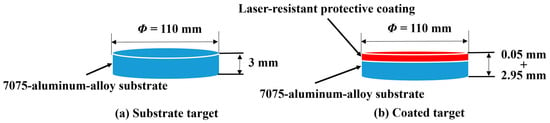
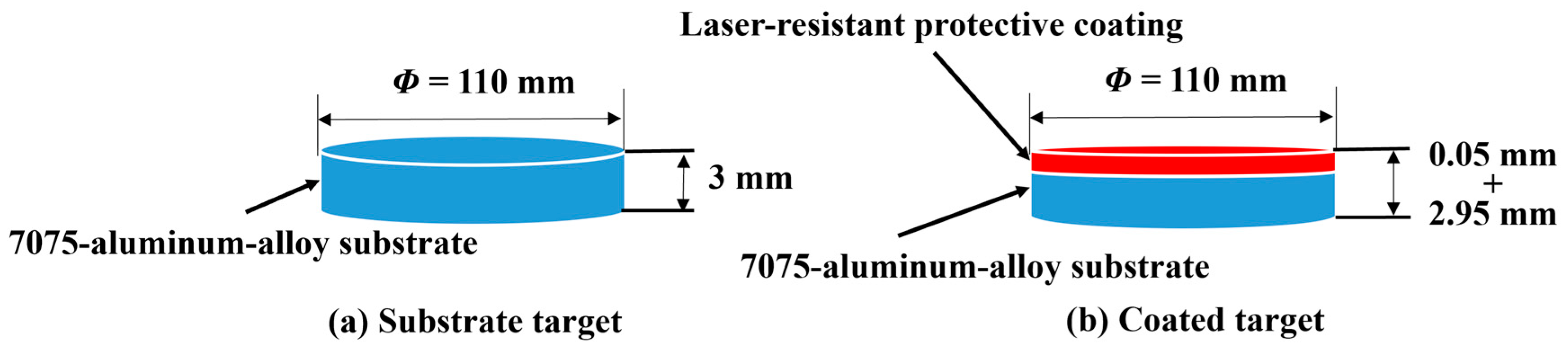
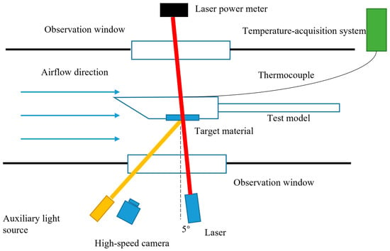
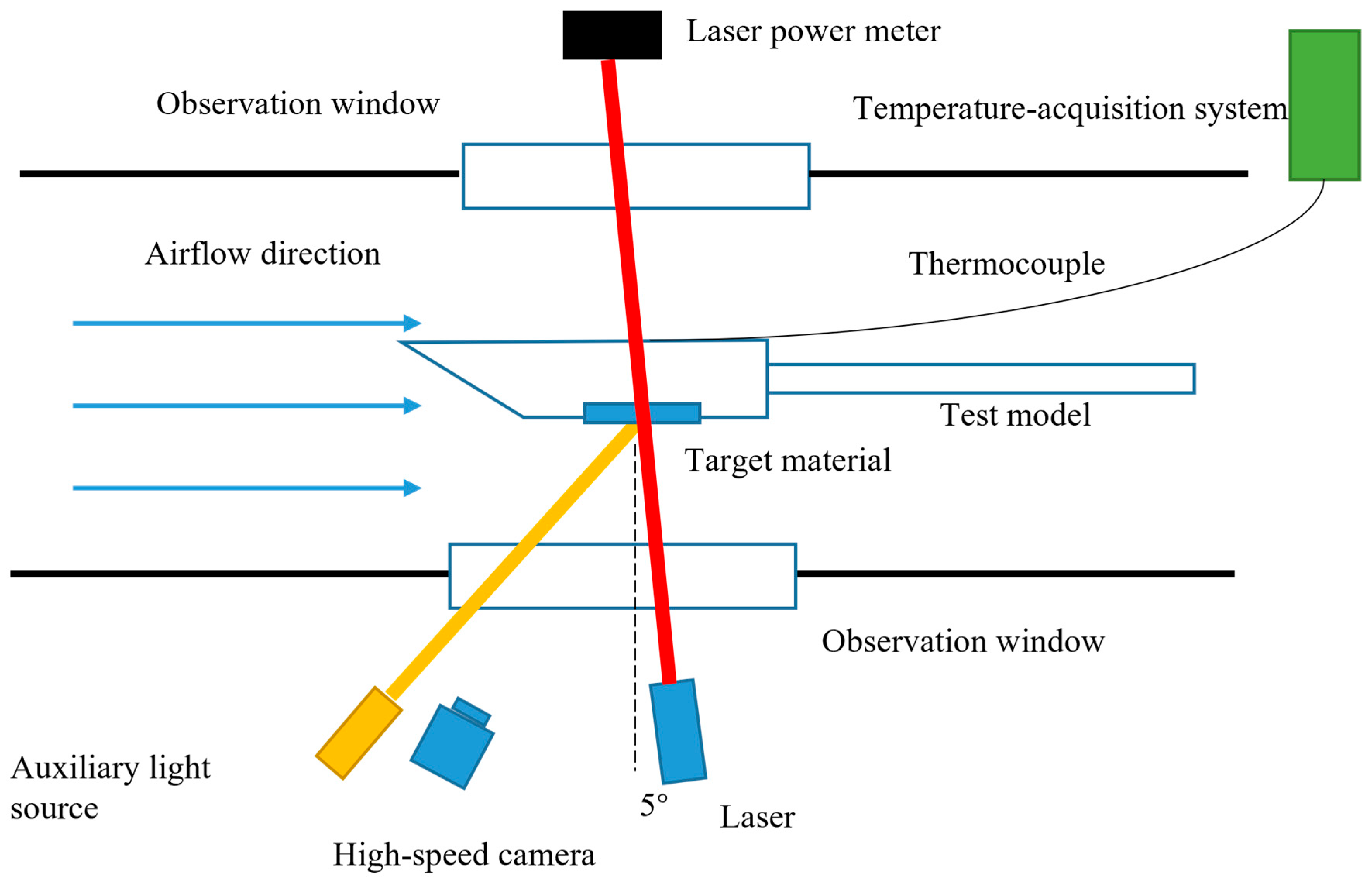
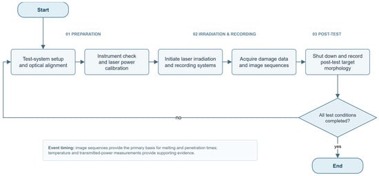
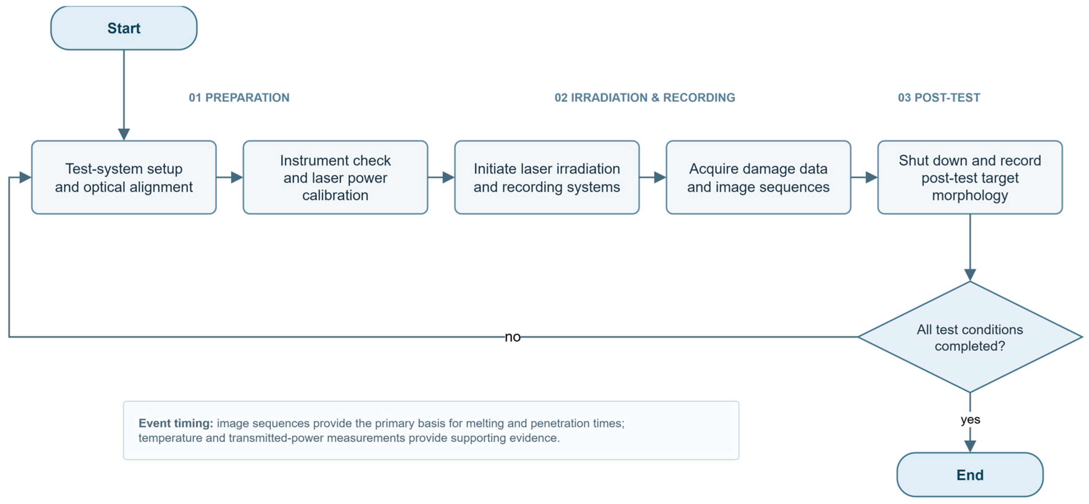
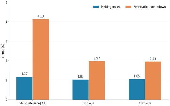
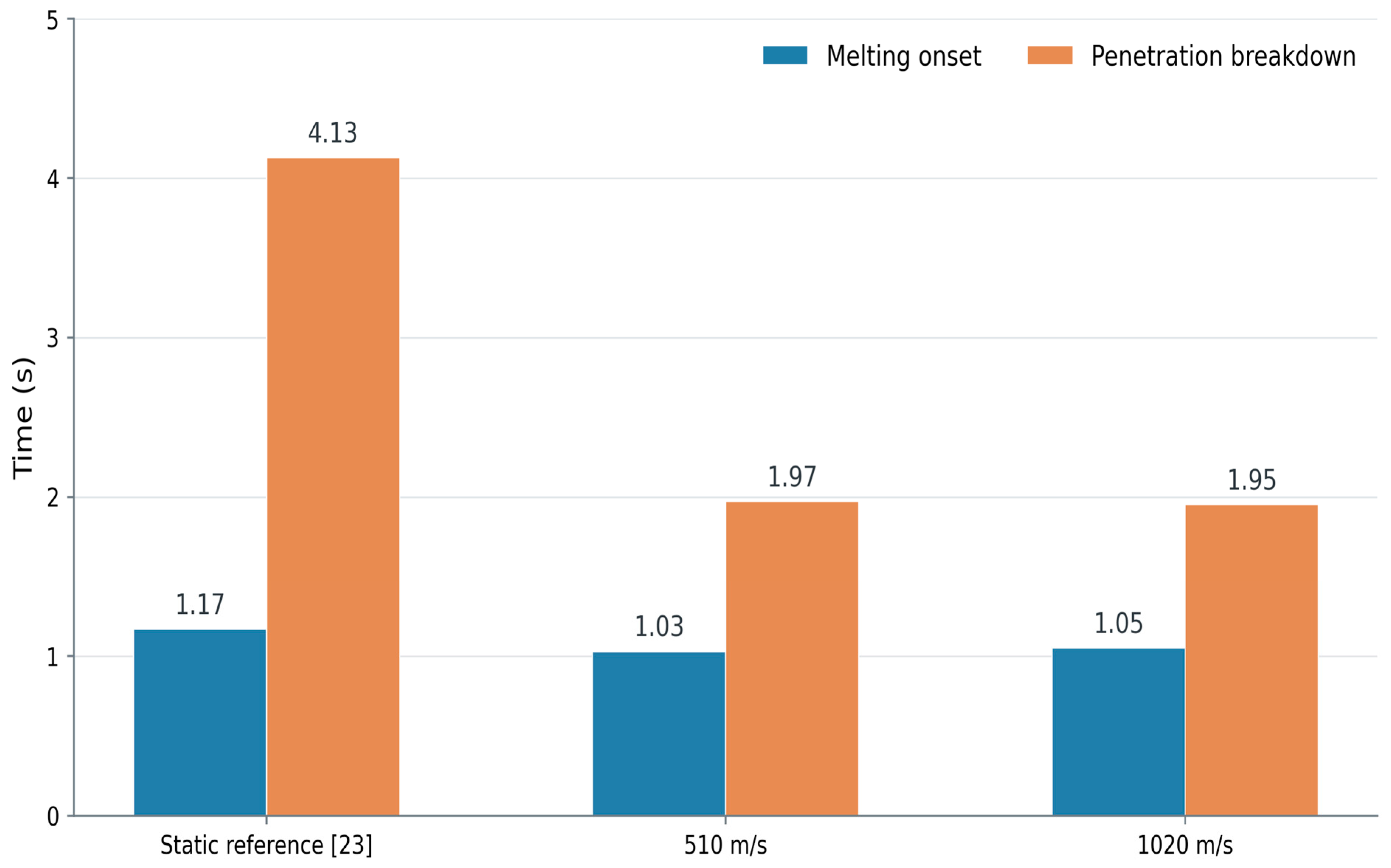
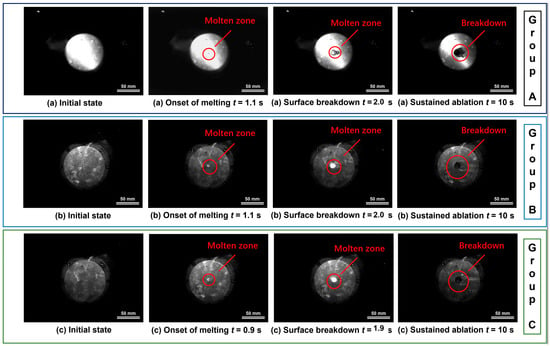
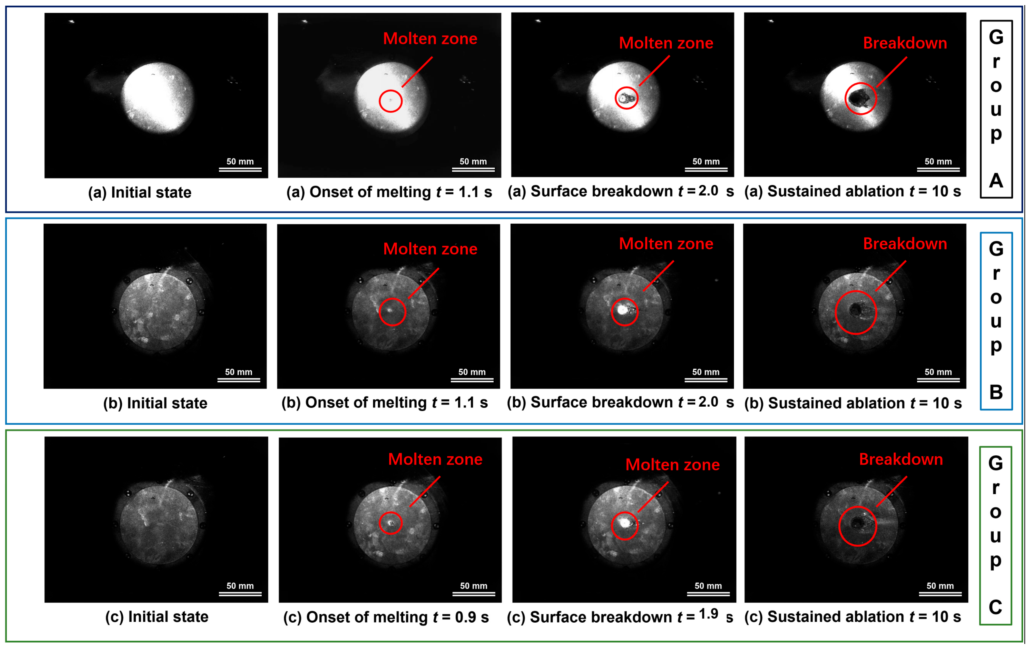
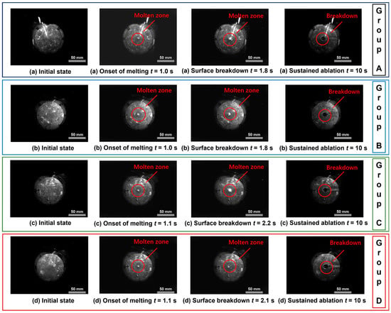
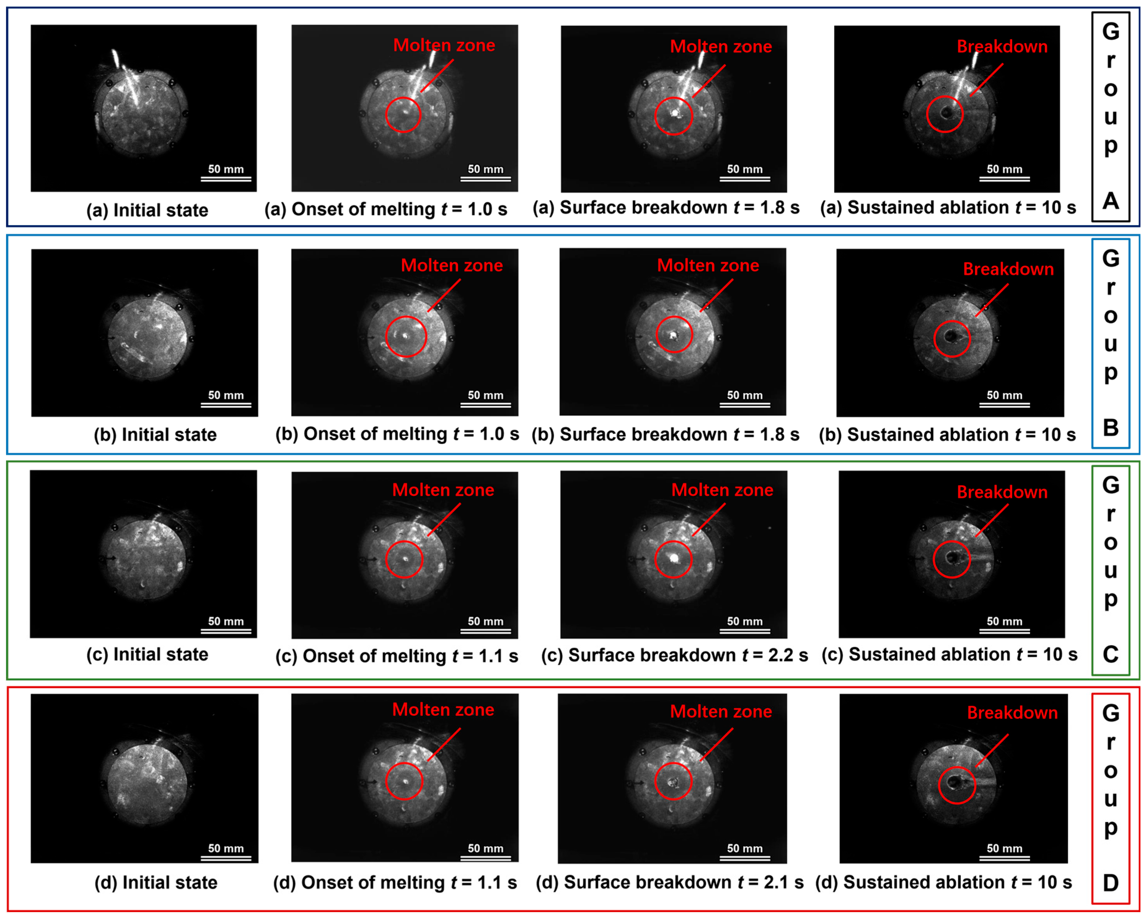
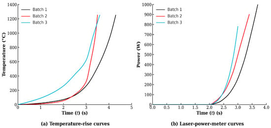
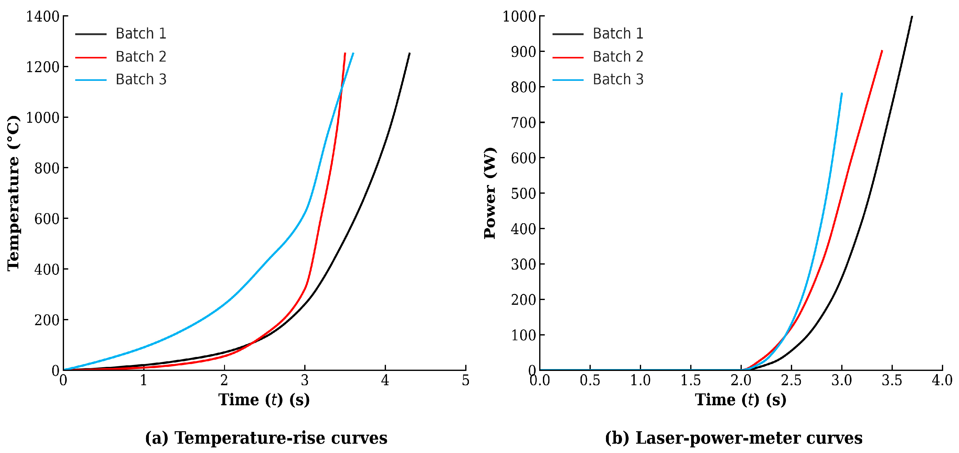
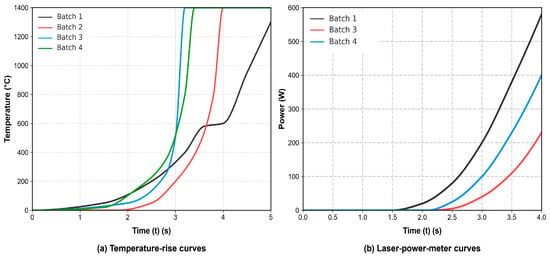
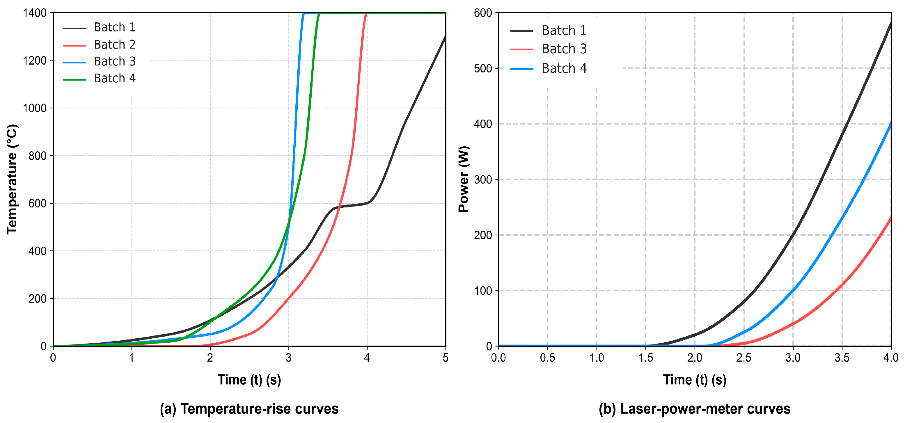
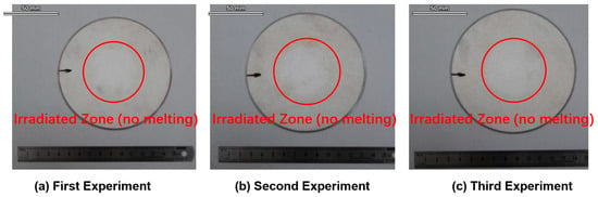
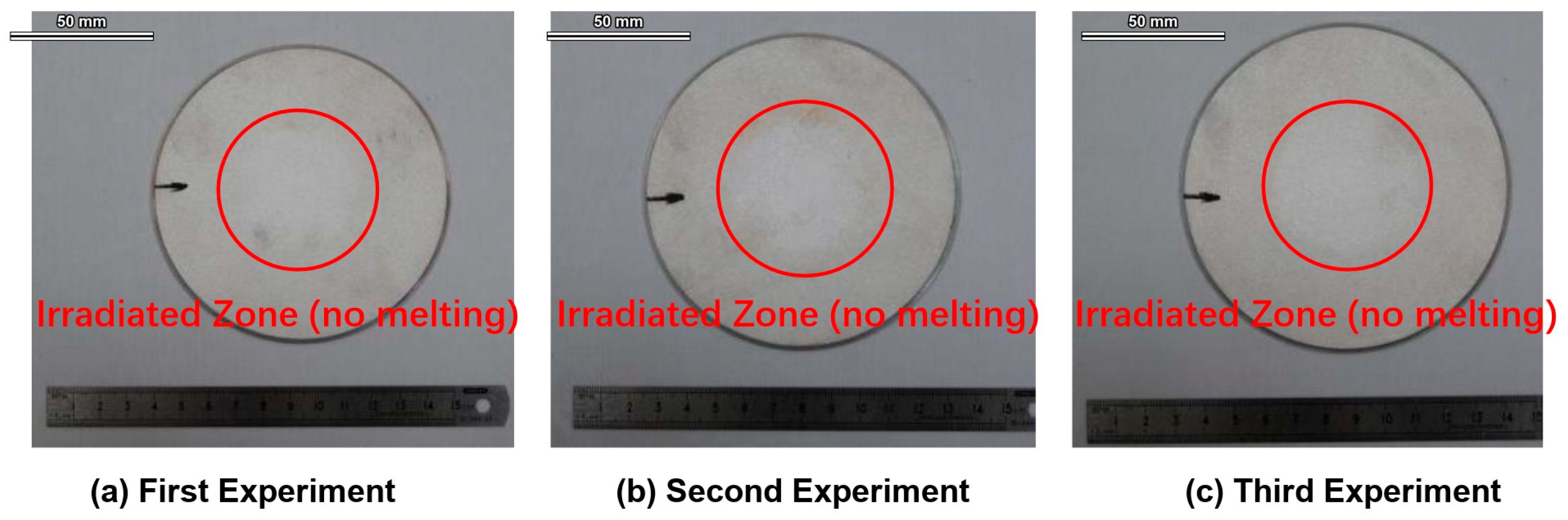
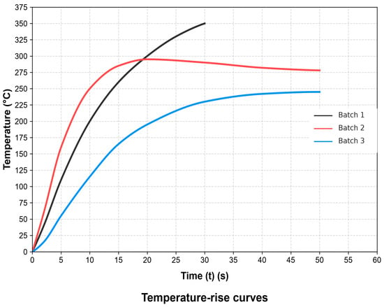
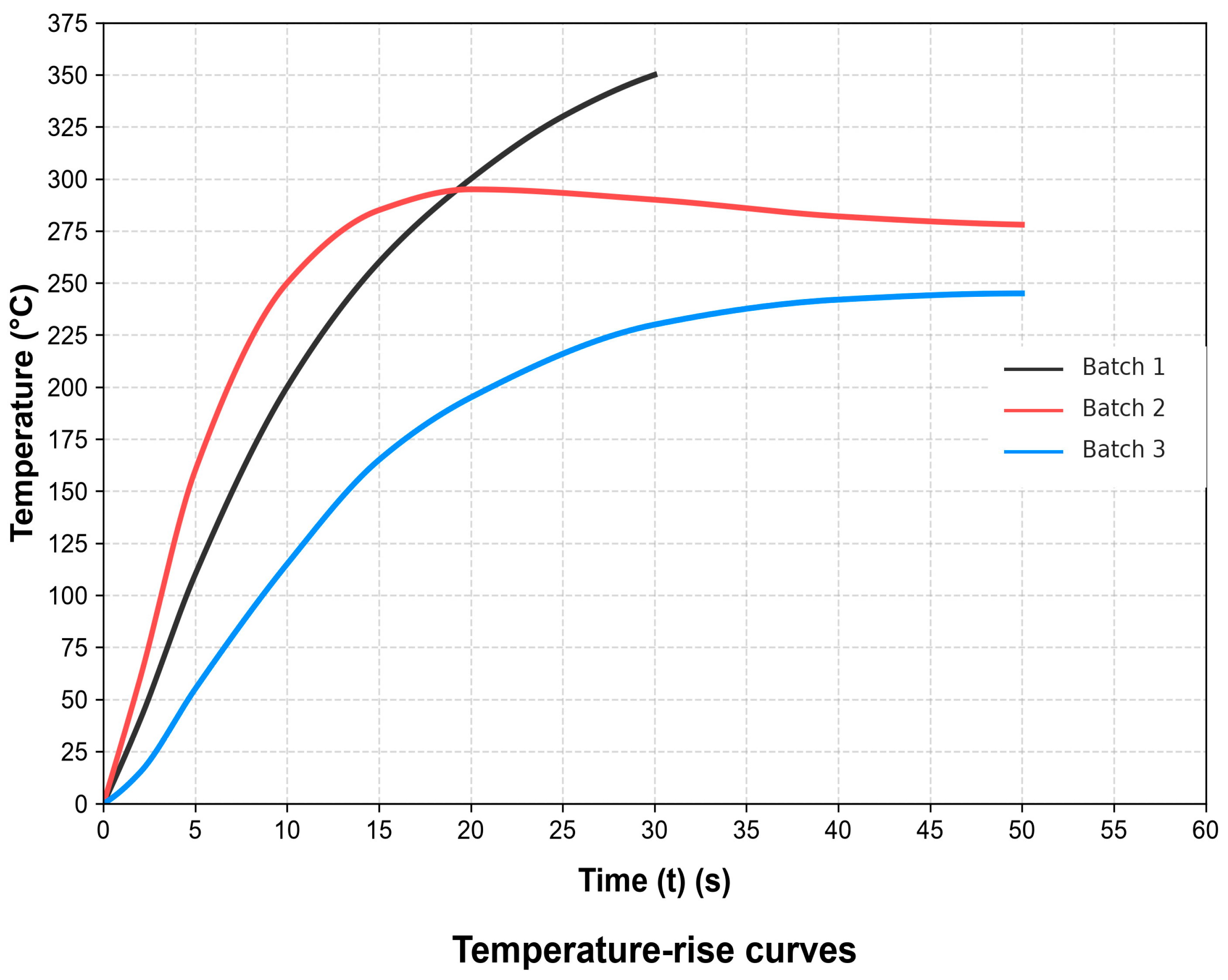
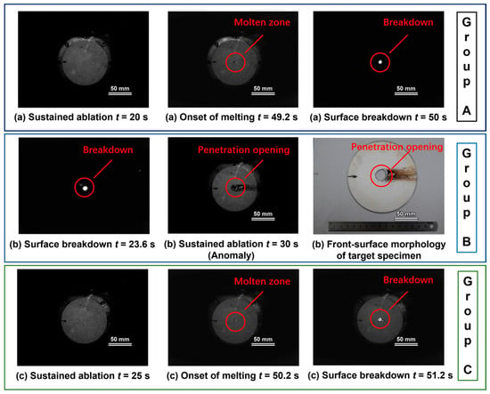
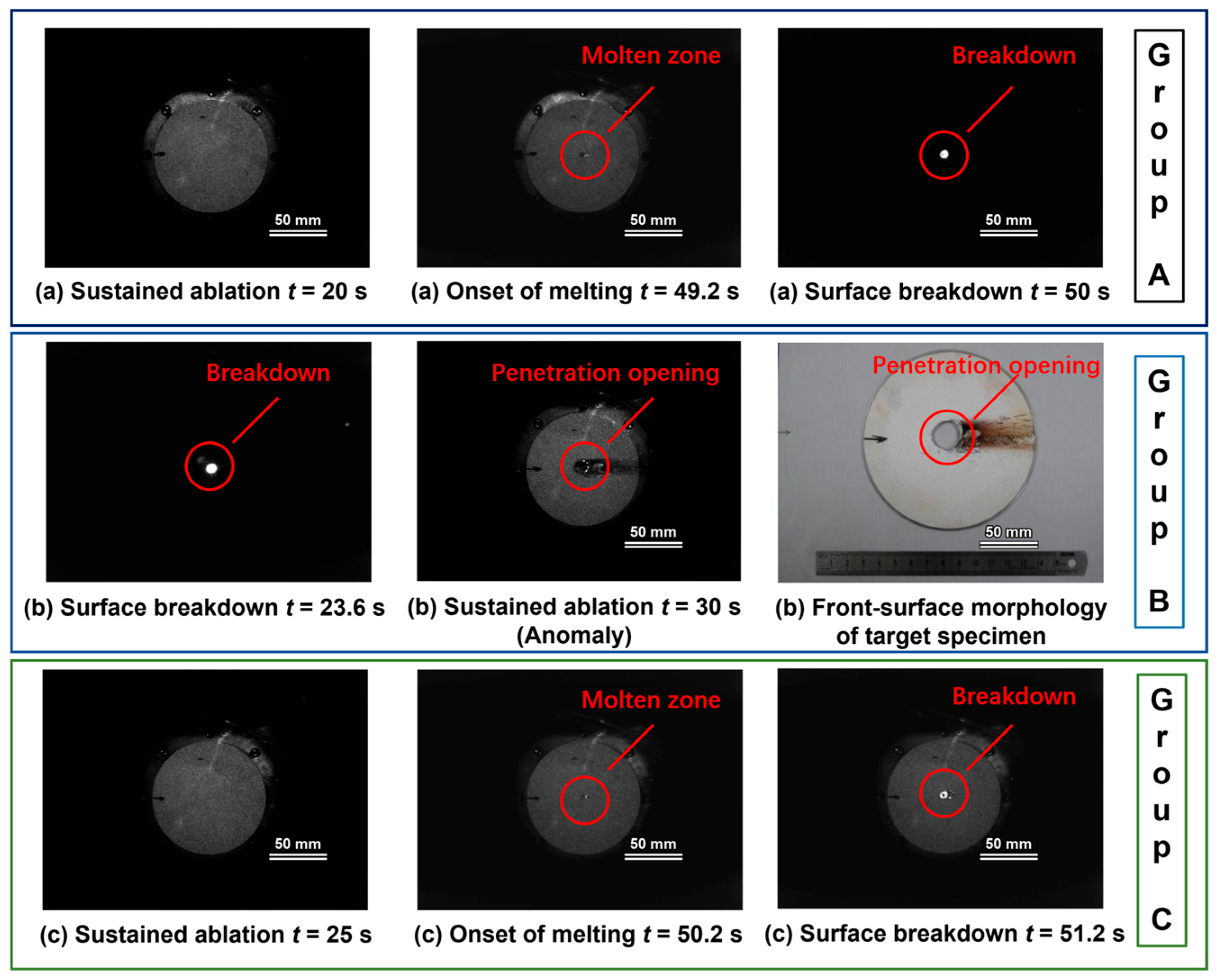
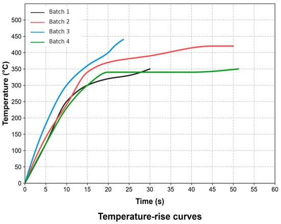
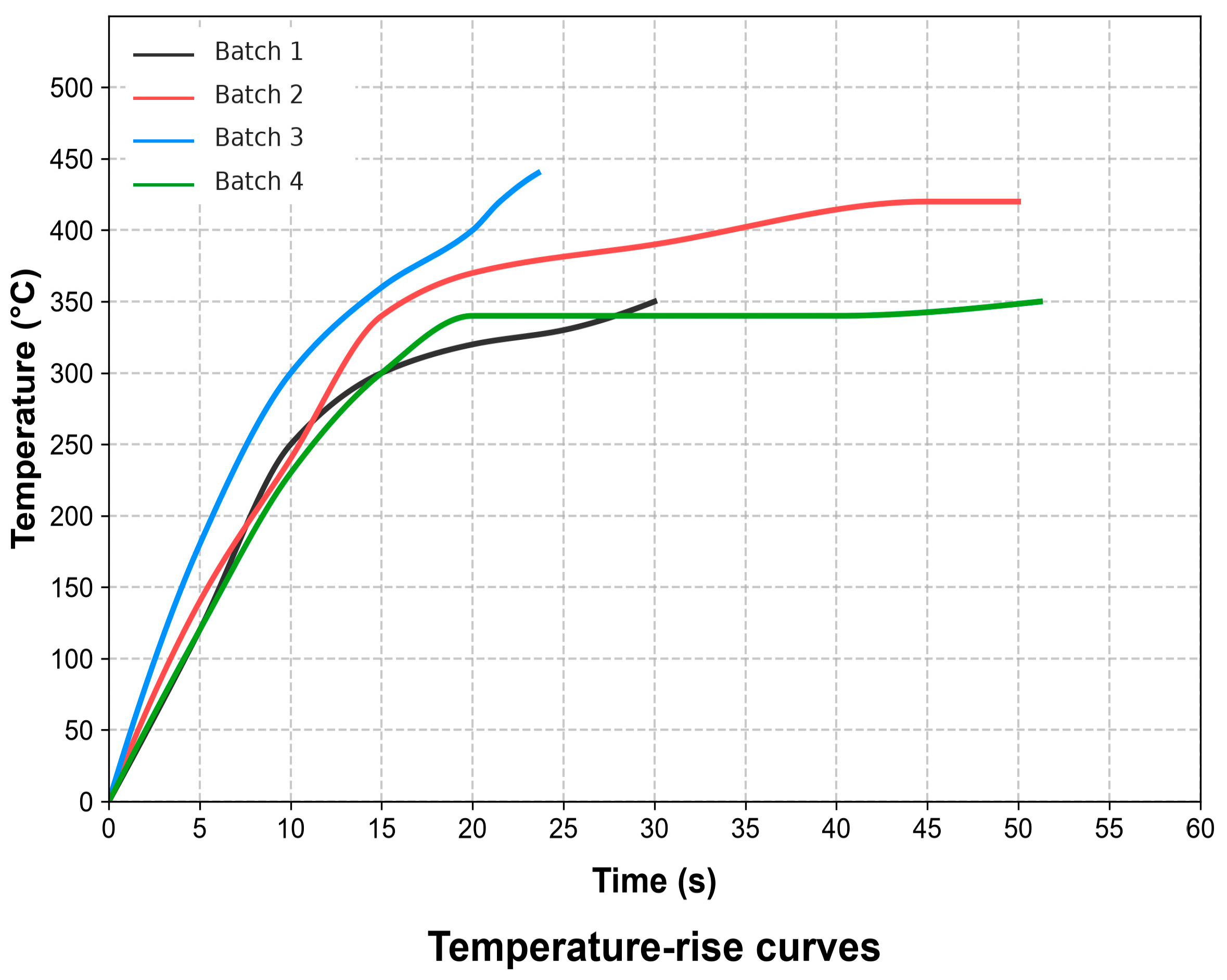
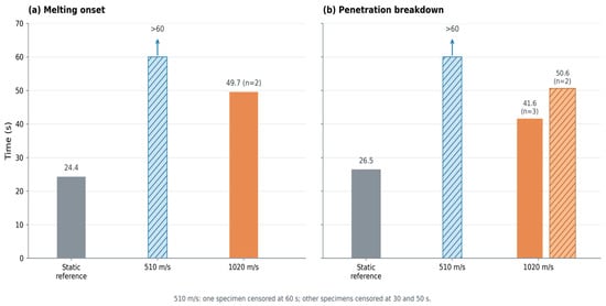
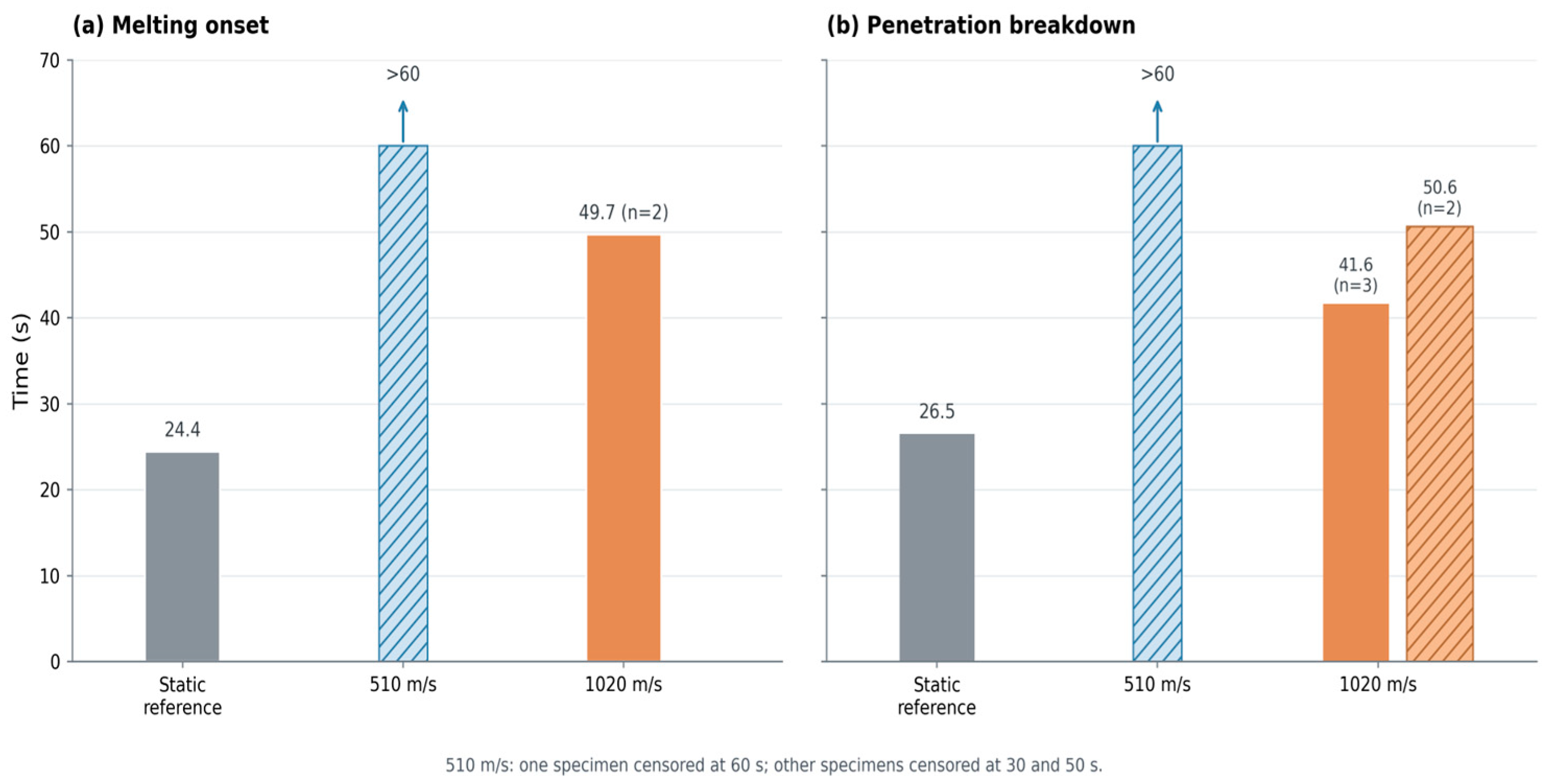
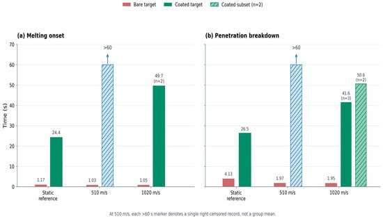
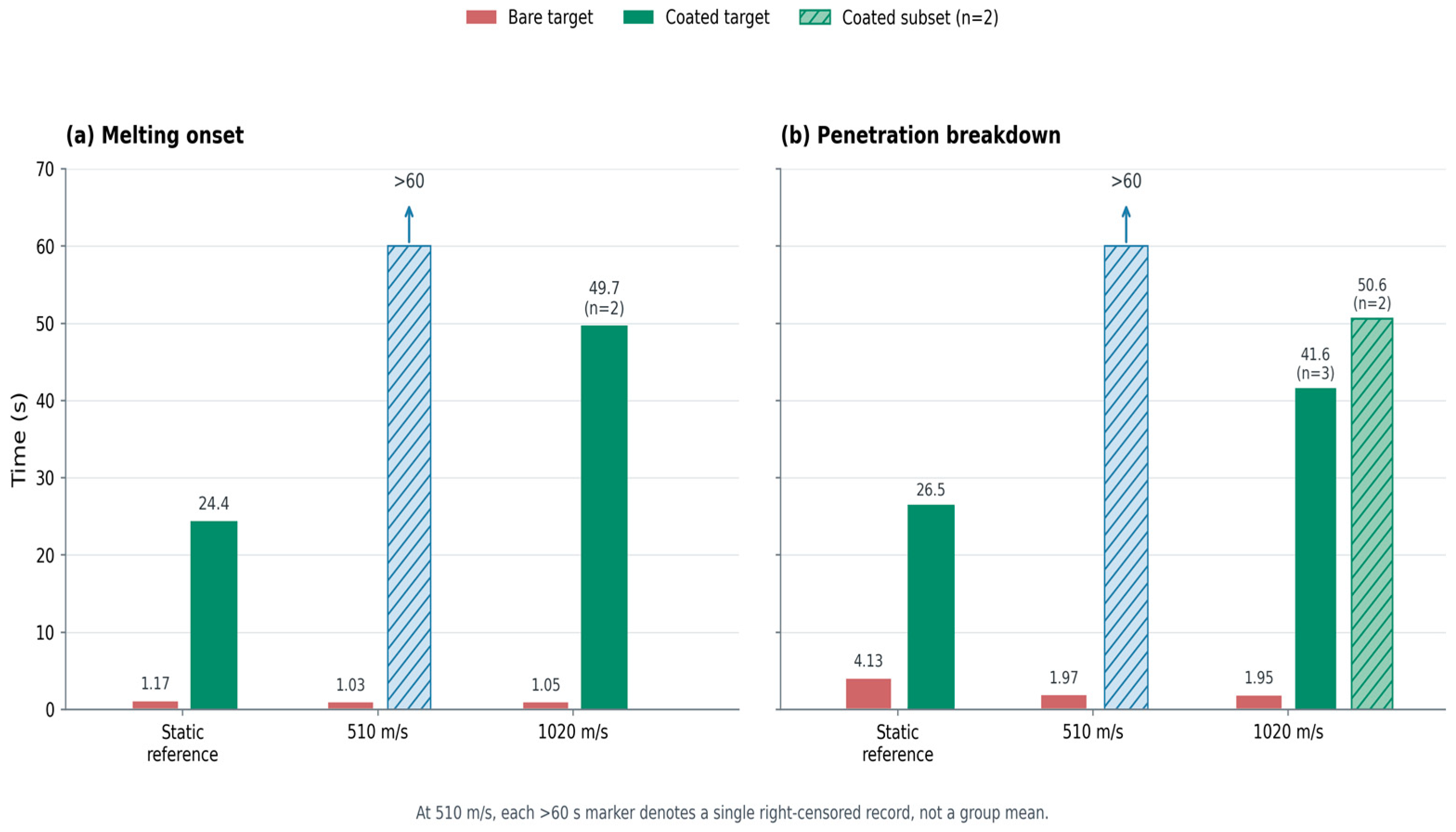

Disclaimer/Publisher’s Note: The statements, opinions and data contained in all publications are solely those of the individual author(s) and contributor(s) and not of MDPI and/or the editor(s). MDPI and/or the editor(s) disclaim responsibility for any injury to people or property resulting from any ideas, methods, instructions or products referred to in the content. |
© 2026 by the authors. Licensee MDPI, Basel, Switzerland. This article is an open access article distributed under the terms and conditions of the Creative Commons Attribution (CC BY) license.