


Abstract
In photonic integrated circuits (PICs), optical isolators and circulators are utilized to protect active devices from backscattering and to reroute the optical signal. An optical circulator based on the LNOI platform is required to possess wide bandwidth and high isolation ratio simultaneously. A 4-port broadband optical circulator for TM mode with high isolation ratio on the lithium niobate on insulator (LNOI) platform is proposed. The circulator, based on the Mach–Zehnder Interferometer (MZI), consists of two 2 × 2 multimode interferometers (MMIs), and a non-reciprocal and reciprocal waveguide. The circulator we designed based on the magneto-optical effect achieved an ultra-wide 30 dB isolation bandwidth of 84 nm. We optimized the configuration of the Ce:YIG/LiNbO3 composite waveguide and 3 dB power splitter/combiner, achieving low-loss and compact non-reciprocal waveguides and MMIs. The total insertion loss is 1.04 dB. The wide bandwidth and low-loss characteristics give our device significant potential for application in high-density photonic integrated circuits.
1. Introduction
The rapid advancements in optical communications, optical interconnects, microwave photonics, and quantum information technologies have created an urgent demand for photonic integrated circuits featuring high speed, broadband, low power consumption, and a compact footprint. Lithium niobate on insulator has emerged as one of the most promising platforms for integrated photonics, by virtue of its excellent electro-optical properties, ultra-low optical loss, and mature manufacturing process [1,2,3].
Despite the emergence of a variety of active and passive photonic devices on the LNOI platform, the development of on-chip non-reciprocal photonic devices has lagged significantly behind, forming a bottleneck restricting high-performance and large-scale photonic integration on LNOI. The main function of an optical isolator is to block back-reflected light from entering lasers, amplifiers, and other active devices, thus reducing the intensity and phase noise in the system and ensuring the stability and high-performance operating state of the system [4,5]. The optical circulator, as an extension of the optical isolator possessing the above functions, is a multi-port optical device serving as a roundabout for photons, enabling bidirectional operation in optical interconnects and increasing the capacity in data centers and communication networks.
The key to realizing optical non-reciprocity is to break the Lorentz reciprocity [6]. Currently, the main methods to achieve optical non-reciprocity include nonlinear effects [7,8,9], spatio-temporal modulation [10,11,12] and magneto-optical effects [13,14,15,16,17,18]. Currently, the implementation of optical isolation on LNOI platforms based on spatio-temporal modulation [19] and nonlinear effect [8] exhibits the drawbacks of extra power consumption or high insertion loss. The isolator based on nonlinear effect achieves a cascaded ring isolation of 35 dB with 5 dB insertion loss. The isolator based on spatio-temporal modulation enables a maximum optical isolation of 48.0 dB with low insertion loss of 0.5 dB, though it has to be assisted with extra microwave drive power of 21 dBm. Compared with the two former methods, non-reciprocal devices based on the magneto-optical effect usually have the advantages of wide bandwidth, low insertion loss, simple structure and independence from circuit control [18]. Yttrium iron garnet (YIG) doped with cerium (Ce) or bismuth (Bi) is a good candidate for magneto-optical devices due to its large Faraday rotation coefficient and low optical absorption loss in the near-infrared band [20,21]. By employing such magneto-optical materials, a magneto-optical isolator on the LNOI platform has been demonstrated, and the device showed a 30 dB isolation bandwidth of about 51.98 nm and 1.20 dB simulated insertion loss [22]. Recently, an optical circulator on the LNOI platform, which exhibited ultrabroadband performance but a relatively low isolation ratio of 15 dB, was implemented by means of traveling-wave modulation [23]. Nevertheless, an optical circulator relying on the magneto-optical effect remains undemonstrated on the LNOI platform, which is an effective approach to simultaneously achieve wide bandwidth and high isolation ratio. In this paper, we proposed a magneto-optical circulator for TM mode on the LNOI platform. The optical circulator adopts an asymmetric MZI structure, including two symmetric 2 × 2 multimode interferometers, a non-reciprocal waveguide and an asymmetric reciprocal waveguide as interference arms. Non-reciprocal phase shift is generated by composite waveguides composing of Ce:YIG and LN. A compact 2 × 2 3 dB power splitter/combiner is used to ensure the function of a four-port circulator. The value of the NRPS is optimized to 4424.42 rad/m and the 30 dB isolation bandwidth reaches up to 84 nm. The total insertion loss of our circulator is estimated to be around 1.04 dB. In addition, the influence of deviations in the key parameter on the central wavelength and isolation bandwidth has been investigated.
2. Methods
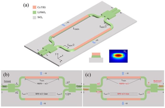
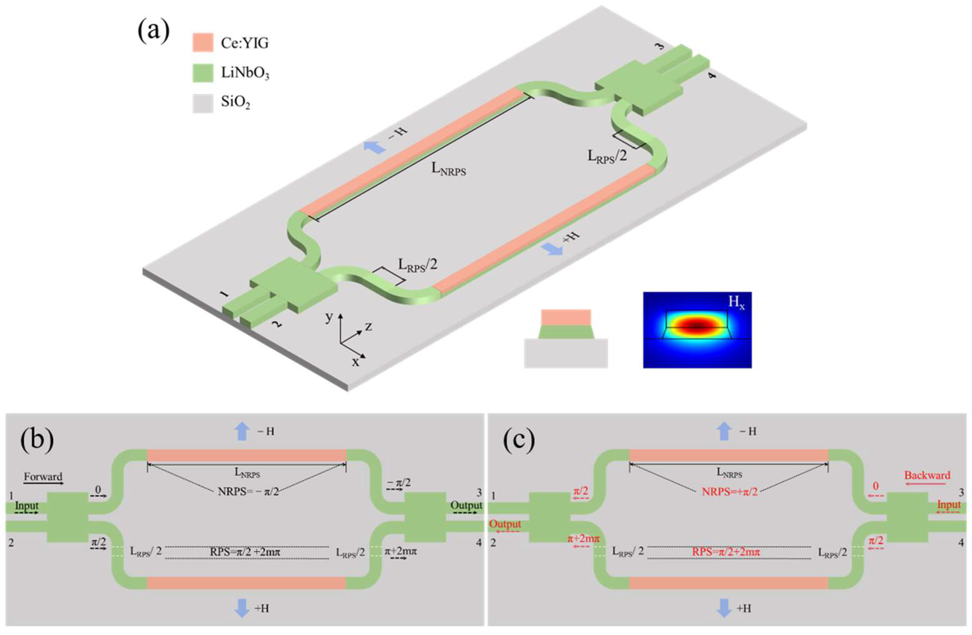
A schematic diagram of the proposed optical circulator built on an LNOI platform is shown in Figure 1a. The circulator is based on an MZI structure and is composed of two same 2 × 2 multimode interferometer couplers and magneto-optical waveguides. The MMI is utilized as a 3 dB power splitter/combiner, while magneto-optic waveguides, formed by Ce:YIG deposited on top of LN waveguides, are employed to induce non-reciprocal phase shifts for TM-polarized light. The cross-section of the magneto-optic waveguides and Hx field distribution are shown in the inset of Figure 1a. The direction of incidence from port 1 is defined as the forward direction.
Figure 1.
(a) Schematic configuration of the optical circulator based on MZI and the cross-section of the magneto-optic waveguides and Hx field distribution. (b) Forward transmission of the optical circulator. (c) Backward transmission of the optical circulator.
The TM-polarized light injected from port 1 is split into two asymmetric interference arms with equal power and an initial phase difference of π/2 by virtue of MMI as shown in Figure 1b. By engineering the lengths of reciprocal and non-reciprocal waveguides, the reciprocal phase difference and non-reciprocal phase difference between two arms can be adjusted respectively as
where m is an integer. Considering the π/2 phase difference accumulated in the first MMI, the accumulated total phase difference before entering the second MMI is
Consequently, the entire optical power is output from port 3 of the second MMI, 3 dB power combiner.
For the backward direction, similarly, the TM-polarized light injected from port 3 will be split by MMI with equal power and a phase difference of π/2 as shown in Figure 1c. The reciprocal phase difference and non-reciprocal phase difference are given by
Under this case, the accumulated total phase difference before entering the second MMI is
Hence, the entire optical power eventually exits from port 2 instead of port 1.
The dielectric constant tensor of MO material can be expressed as:
where is the off-diagonal term of Ce: YIG, is the refractive index, is the wavelength of light, and is the Faraday rotation coefficient of MO material. Due to the influence of off-diagonal terms, the forward and backward propagation constants , are different. The non-reciprocal phase shift (NRPS) is defined as the difference of two propagation constants [24]:
where is the propagation constant for the fundamental TM mode, and and are the angular frequency and vacuum dielectric constant, respectively. is the normalized power flow along the z direction.
3. Simulation and Results
This optical circulator is designed on an X-cut LNOI platform with a 500 nm thick lithium niobate thin film and a 2 μm SiO2 insulation layer. The ordinary and extraordinary refractive indices of LN are no = 2.21 and ne = 2.14, respectively. The refractive indices of Ce: YIG and SiO2 are nCe:YIG = 2.20 and nSiO2 = 1.44 at a wavelength of 1550 nm, respectively. The Faraday rotation coefficient of Ce: YIG is . The sidewall angle is set at 75° to match the manufacturing process. The Finite Difference Eigenmode (FDE) and Finite-Difference Time-Domain (FDTD) methods are employed to simulate and analyze the structural parameters and performance of our proposed optical circulator.
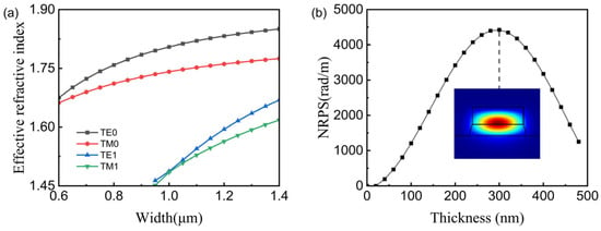
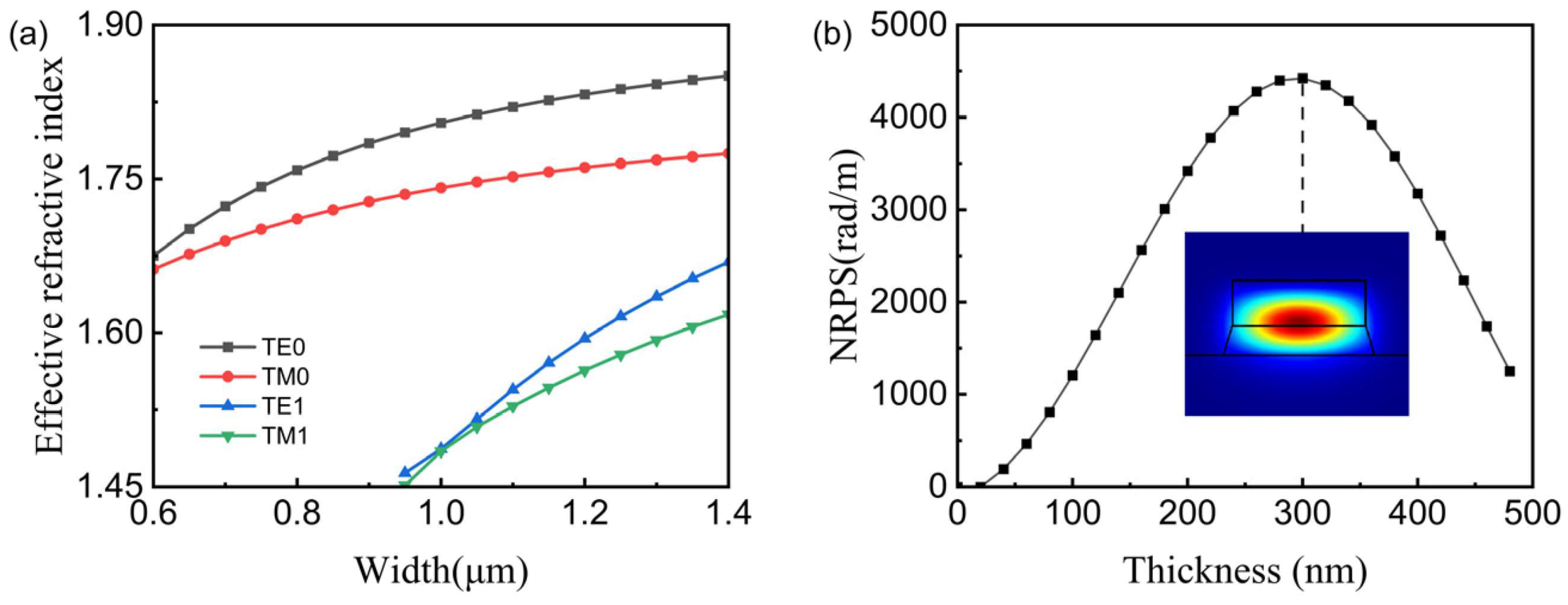
Single-mode operation is essential in non-reciprocal photonic devices because higher-order modes introduce modal crosstalk, modal dispersion and unexpected propagation loss, which severely degrade device performance. In addition, multimode transmission implies that non-reciprocal phase shifts specific to different modes will be generated in the magneto-optical waveguide, making it difficult to achieve the ideal phase interference conditions, thereby restricting the operating bandwidth of the circulator. Figure 2a shows the influence of waveguide dimensions on the number of supported guided modes and effective refractive index of different modes at the wavelength of 1550 nm. The width of the waveguide in the circulator was ultimately determined to be 800 nm to ensure single-mode operation.
Figure 2.
(a) The effective refractive index of TE0, TM0, TE1, TM1 modes as a function of widths of LN waveguide. (b) NRPS of Ce: YIG/LN waveguide with different . The inset shows the H intensity distribution of the fundamental TM mode in the MO waveguide.
To acquire a compact optical circulator with low loss, the value of the NRPS should be as large as possible to reduce the length of the NRPS waveguide. Hence, the impact of the thickness of the top Ce: YIG layer on the NRPS should be simulated and investigated. Figure 2b illustrates the variation in the NRPS of MO waveguides with different thicknesses of the Ce: YIG layer at the wavelength of 1550 nm. According to Figure 2b, the NRPS reaches its maximum value of 4424.42 rad/m when the thickness of the magneto-optical layer is 300 nm and the inset shows the H intensity distribution of the fundamental TM mode in the MO waveguide. According to Equation (1), the non-reciprocal phase difference of the two interference arms should be π/2 to satisfy the interference conditions required for isolation and the length of the NRPS waveguide in the MZI can be calculated as 355.03 μm.
The 3 dB MMI in this circulator is a paired-interference MMI. The input positions of the paired-interference MMI are located at ±we/6. Under this condition, the self-imaging length of the multimode interference coupler is reduced to one-third of that for a general interference MMI, thereby shortening the length of the multimode interference region. The N-fold image positions of the paired-interference MMI are given by [25]:
represents the beat length, defined as the propagation distance required to accumulate a phase difference between the fundamental mode and the first-order mode, which can be calculated by:
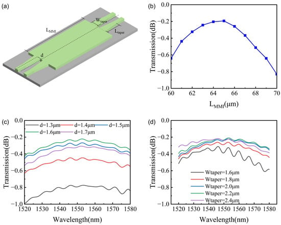
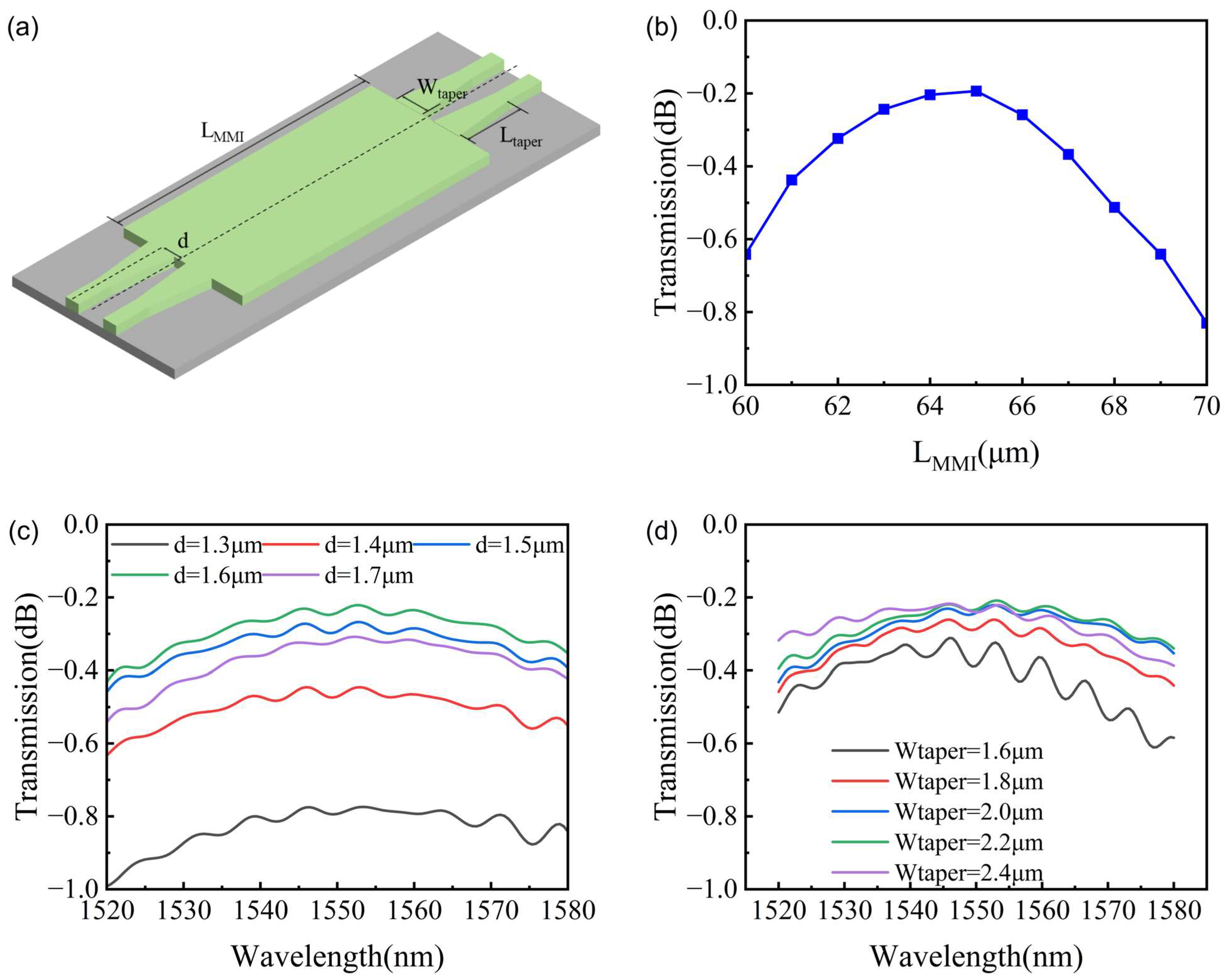
where We represents the effective width. Figure 3a shows the schematic of the 2 × 2 MMI used in the circulator. The width of the multimode region is determined as 9 μm to reserve adequate gap between two ports. According to Equation (8), the length of the multimode waveguide region is calculated to be around 67 μm. To determine the optimal imaging position of the multimode region, we simulated the transmission of MMI with different lengths at the wavelength of 1550 nm, as shown in Figure 3b. Two beams of equal power with a 90° phase difference are input into the MMI from the left and the light output from the right upper waveguide. It can be observed that the transmittance reaches its maximum when L is equal to 65 μm.
Figure 3.
(a) Schematic of 2 × 2 MMI splitter/combiner. (b) The simulated transmission as a function of LMMI. (c) The simulated transmission of MMI with different values of d. (d) The simulated transmission of MMI with different Wtaper.
The tapered waveguide is adopted as a transition to reduce the coupling loss between the single-mode waveguide and the multimode interference region. To determine the optimal position of the input/output waveguide, LMMI was fixed at the value of 65 μm and the tapered waveguide length was set to 10 μm. Two equal power TM mode signals with a 90° phase difference are input into the MMI from the left; by varying d, the transmission of the right upper waveguide in the wavelength range of 1520–1580 nm was obtained, as shown in Figure 3c. It can be seen that the transmittance reaches its maximum when d is equal to 1.6 μm.
Furthermore, we simulated the transmission of MMI with different widths of the tapered waveguide for obtaining appropriate Wtaper. It can be seen that the loss of MMI can be reduced to 0.25 dB by increasing Wtaper to 2 μm and further increasing the value of Wtaper does not lead to a substantial improvement in the propagation loss. Moreover, the reduction in the gap between two tapered waveguides would result in undesired crosstalk.
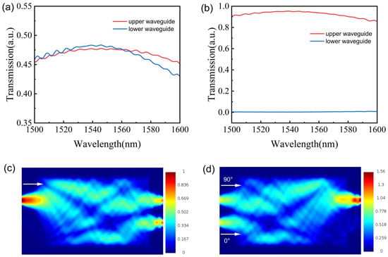
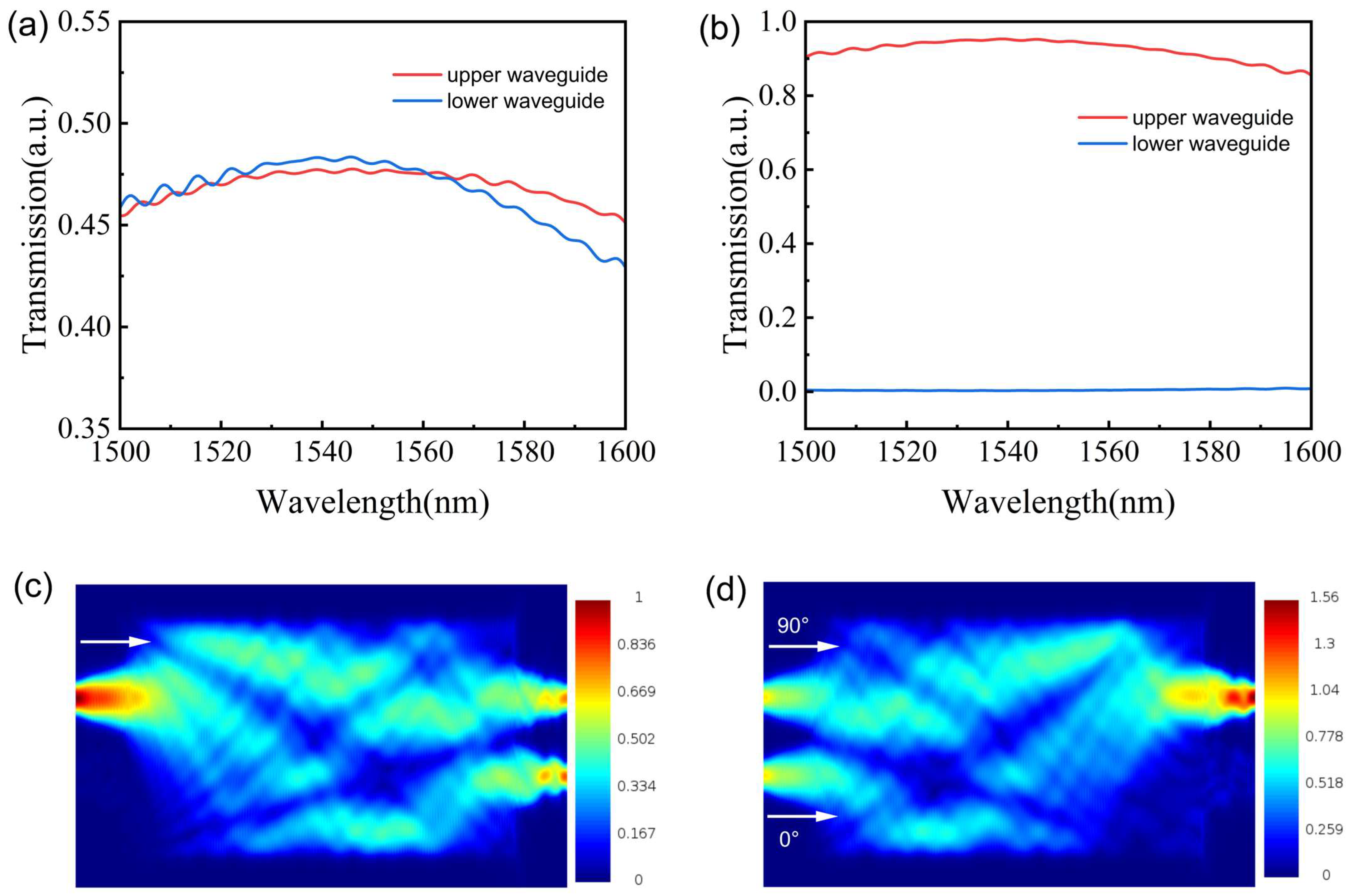
Based on the MMI structural parameters obtained from the above optimization, the transmission spectra of the MMI serving as the power splitter and combiner, respectively, were simulated over the wavelength range of 1500–1600 nm. Figure 4a shows the transmission spectrum when the incident light enters from port 1 and the MMI acts as a 3 dB power splitter. The white arrow represents the direction of the incident light. Figure 4b presents the transmission spectrum when the MMI serves as the power combiner at the end of the circulator. In this case, two beams of equal power with a 90° phase difference are input into the MMI and then output from port 3. The input optical signal simulated here corresponds to the situation where, after passing through the first MMI and the asymmetric interferometer arms within the circulator, the light enters the output-end MMI. Figure 4c,d illustrate the evolution of the electric field transmission within the MMI for these two scenarios, respectively.
Figure 4.
(a) The simulated transmission spectrum when the MMI functions as power splitter. (b) The simulated transmission spectrum when the MMI functions as power combiner. (c) Electric field intensity of the power splitter. The white arrow indicates the direction of the incident signal. (d) Electric field intensity of the power combiner. The white arrows indicate the directions of the incident signals and the initial phases are set to 90° and 0°, respectively.
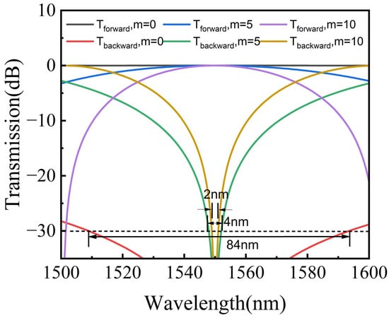
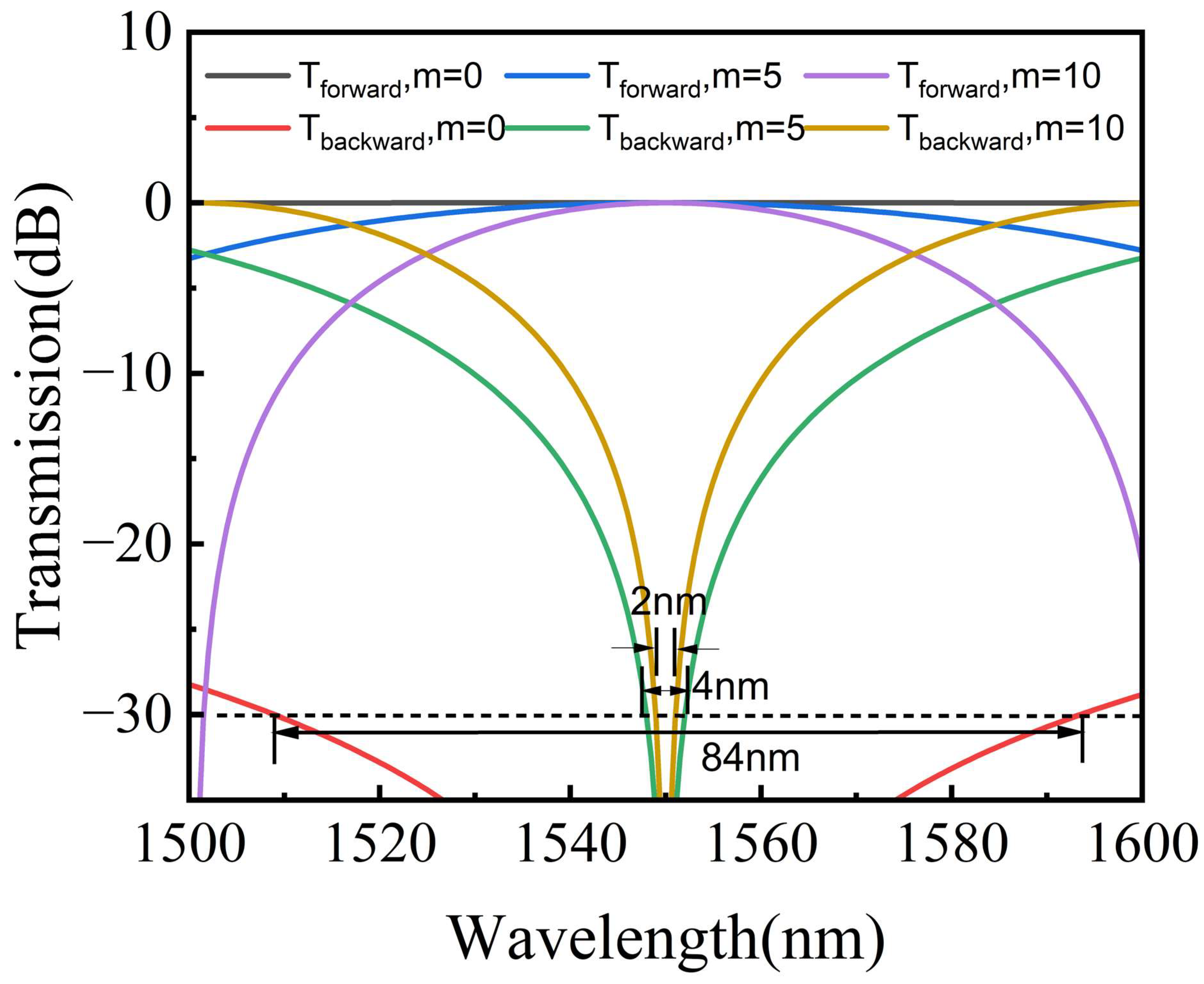
To investigate the influence of reciprocal waveguides on the isolation and bandwidth of the circulator, assuming the 3 dB MMI operates under ideal conditions and the loss of MMI is addressed separately in the subsequent analysis, the forward and backward transmission of the optical circulator with different values of m at the wavelength of 1500–1600 nm is presented in Figure 5. The transmittance between port 1 and 3 can be calculated using Equation (10).
Figure 5.
The simulated transmission spectrum between port 1 and port 3.
As illustrated in Figure 5, the device exhibits a 30 dB isolation bandwidth of 84 nm at m = 0. As the length of the reciprocal waveguides increases, the 30 dB isolation bandwidth gradually decreases to 4 nm and 2 nm when m = 5 and m = 10, respectively.
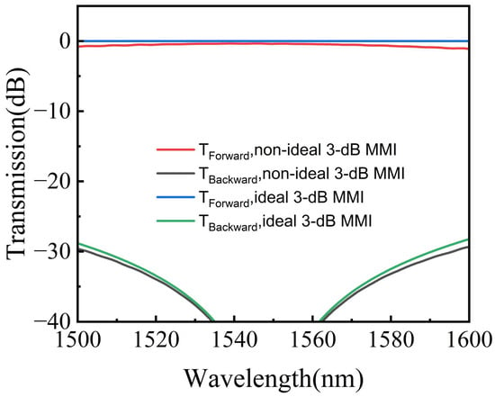
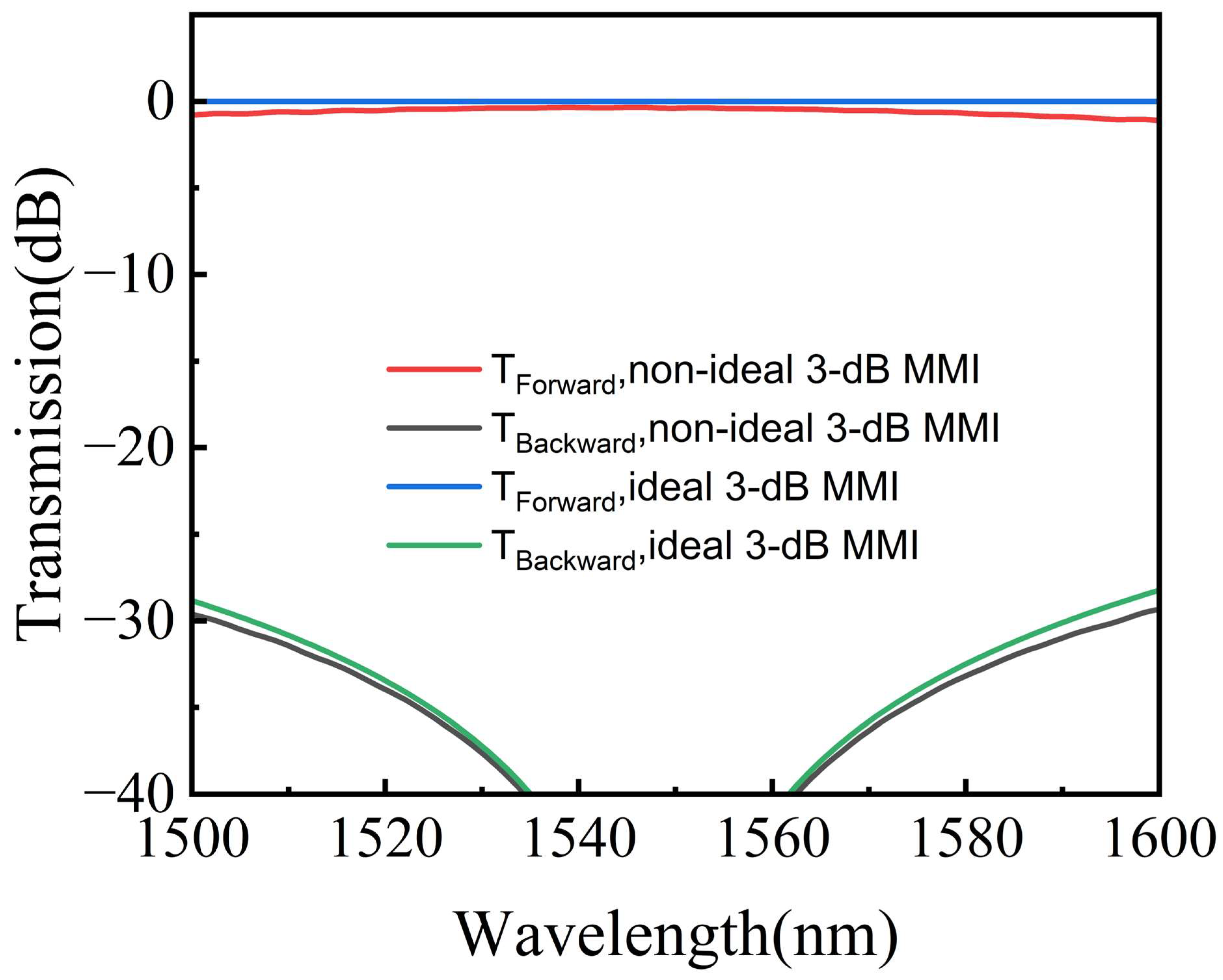
To achieve an accurate evaluation of device performance, the influence of the simulated wavelength-dependent MMI response should be incorporated. By substituting the MMI response simulated with FDTD solution into the transfer matrix of the MZI device, the transmission response of the device under non-ideal conditions was calculated. Figure 6 shows the simulated transmission spectra when 3 dB MMI is under ideal and non-ideal conditions. Under non-ideal conditions, the presence of the two MMIs introduces a 0.38 dB loss to the device at the center wavelength of 1550 nm, while the 30 dB isolation bandwidth is 84 nm.
Figure 6.
The simulated transmission spectra under ideal and non-ideal conditions.
The insertion loss of our optical circulator originates from the MMIs, reciprocal waveguide, non-reciprocal waveguide, as well as the coupling loss between the reciprocal and non-reciprocal waveguides. Considering the small refractive index difference between LN and YIG, the mode overlap integral in the reciprocal and non-reciprocal waveguides is close to 100%, and the coupling loss of this part can be neglected [22]. The loss of the non-reciprocal waveguide mainly originates from the absorption loss of Ce:YIG, which is set as 42 dB/cm [26]. The transmission loss of the fully etched LN waveguide is set as 0.5 dB/cm based on the current fabrication technology. The propagation loss of SiO2 and air can be regarded as 0 at 1550 nm. The confinement factor can be calculated as:
The of Ce:YIG and LN in the NRPS waveguide is simulated to be 44.08% and 33.81%, respectively. The length of the NRPS waveguide in each interference arm is 355.03 μm and the loss of the NRPS waveguide can be calculated as 0.66 dB. Therefore, the total loss of the optical circulator is around 1.04 dB.
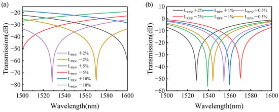
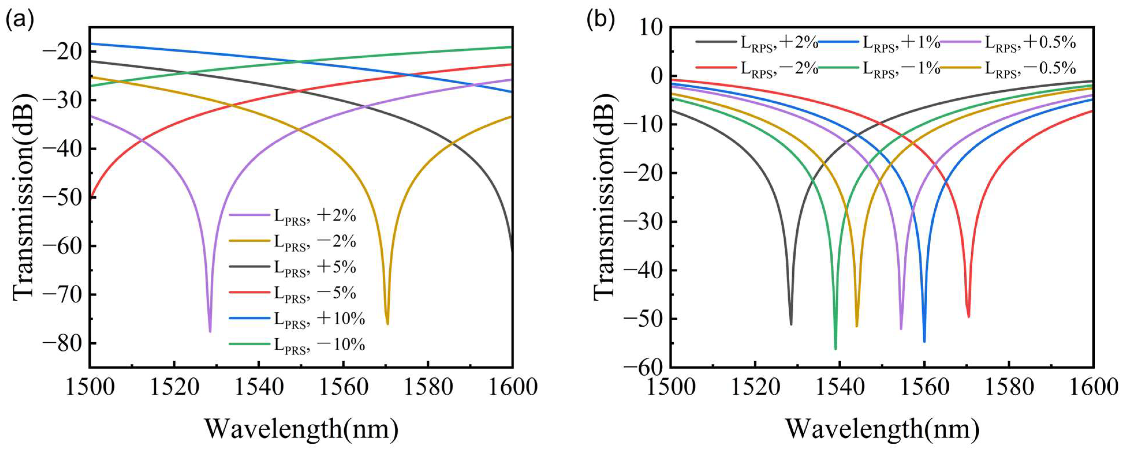
During the fabrication of integrated photonic devices, inevitable fabrication errors will be induced by the inherent limitations of microfabrication technologies, which may deviate the actual structural parameters from the designed target values and eventually degrade its overall performance. For MZI-type magneto-optical circulators, the length of the reciprocal waveguide, as a key structural parameter that determines the reciprocal phase difference between the two arms of the MZI, directly governs the isolation ratio and isolation bandwidth. To evaluate the fabrication tolerance of the reciprocal waveguide length, backward transmission curves with different deviations in length of reciprocal waveguide were calculated, as shown in Figure 7. For the case of m = 0, corresponding to a RPS waveguide length of 0.226 μm, a 20 dB isolation ratio at 1550 nm can be maintained with a length deviation up to 10%, even though the actual central wavelength is considerably shifted away from the designed value. In comparison, for m = 5, corresponding to a RPS waveguide length of 4.753 μm, 20 dB isolation at 1550 nm can still be achieved with a length deviation of 0.5% and the isolation ratio degrades significantly as the deviation increases further. Nevertheless, owing to the smaller free spectral range (FSR), the shift of the central wavelength is relatively less than the former.
Figure 7.
The simulated backward transmission spectra with different deviations in length of reciprocal waveguide. (a) m = 0. (b) m = 5.
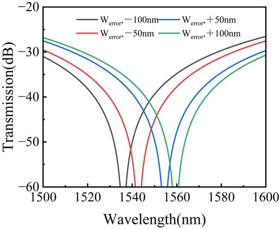
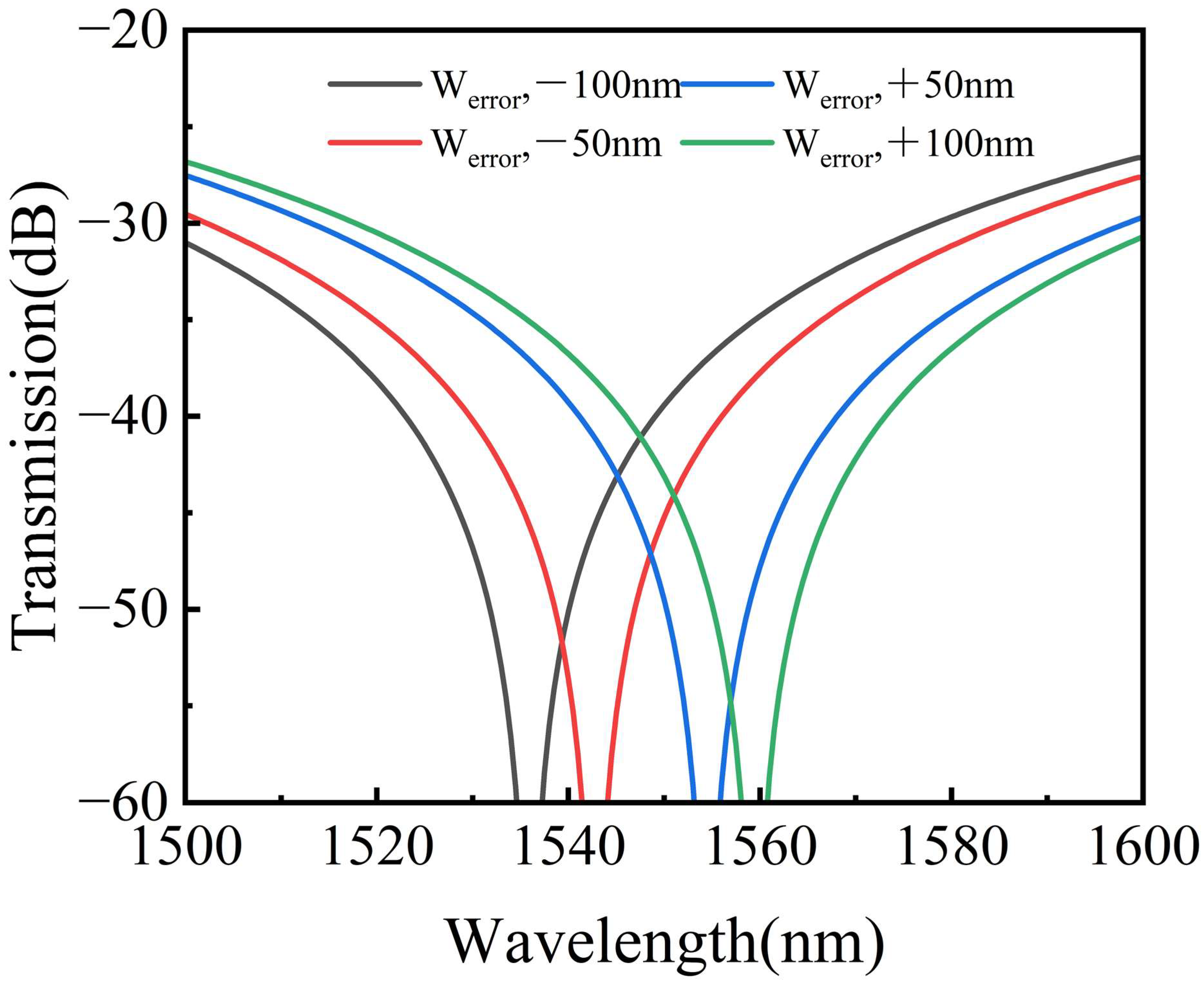
Apart from the length of the reciprocal waveguide, the variation in waveguide width also has an impact on the device performance. Figure 8 illustrates the effect of the errors in width of LN waveguides on the backward transmission spectra for the case of m = 0. It was found that the center wavelength shifts away from 1550 nm when the errors in width increased. However, the 30 dB isolation bandwidth remains above 70 nm.
Figure 8.
The simulated backward transmission spectra with different errors in the width of LN waveguide.
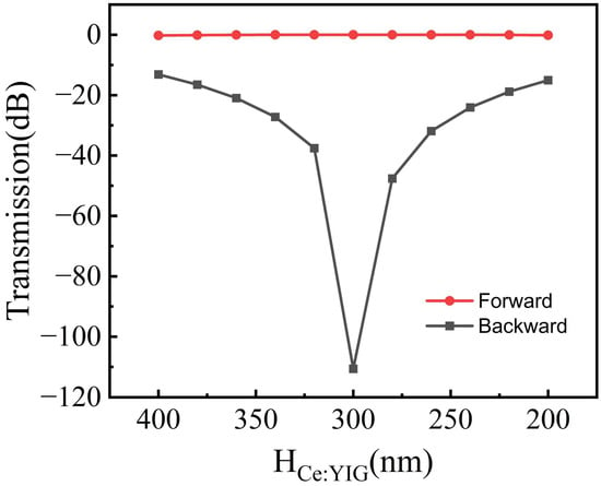
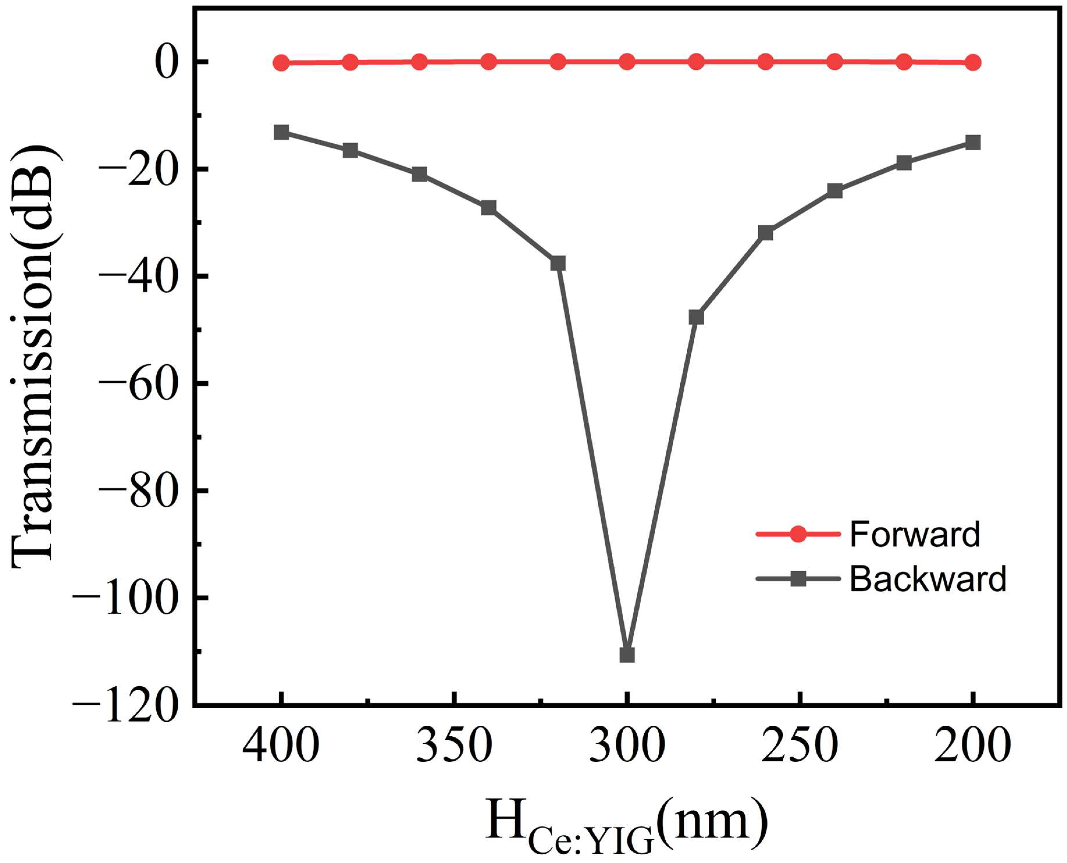
Another important factor that can influence device performance is the accuracy of the magneto-optical material thickness. The forward and backward transmittances at the central wavelength of 1550 nm were calculated with different thickness deviations when m = 0, as shown in Figure 9. It is found that the 30 dB isolation ratio can be maintained at the central wavelength when the thickness varies from 240 nm to 330 nm.
Figure 9.
The forward and backward transmittances at the central wavelength of 1550 nm as a function of thickness of Ce:YIG.
The performance of the optical circulator we designed and other broadband optical isolators is shown in Table 1.
Table 1.
Performance of broadband optical isolators and circulators.
4. Conclusions
A four-port optical circulator for TM mode based on an MZI is proposed on an LNOI platform. The structure utilized LN/Ce: YIG composite waveguides to generate the NRPS in the two interference arms of MZI. By optimizing the structural parameters of the magneto-optical waveguide, the NRPS reaches 4424.42 rad/m, allowing the device to achieve a large isolation with a small size. 2 × 2 MMIs were designed with compact size to utilize a 3 dB power splitter and combiner to achieve the function of a 4-port circulator. The circulator has a 30 dB isolation bandwidth of 84 nm and the total loss of the optical circulator is around 1.04 dB. The proposed optical circulator exhibits good performance in terms of bandwidth and the insertion loss is superior to that of isolators based on other platforms [17,18,29,30]. Meanwhile, the isolation ratio is higher than that of optical circulators based on spatio-temporal modulation methods on the same LNOI platform [23]. The fabrication tolerance of the reciprocal waveguide length was calculated. Owing to its wide bandwidth and high isolation ratio, the optical circulator we designed shows great application potential in high-density photonic integrated circuits based on the LNOI platform.
Author Contributions
Conceptualization, H.Z. and J.L. (Jinye Li); methodology, H.Z. and J.Z.; software, H.Z. and Y.Z.; validation, H.Z. and M.L.; writing—review and editing, H.Z. and J.L. (Jinye Li); supervision and project administration, J.L. (Jianguo Liu). All authors have read and agreed to the published version of the manuscript.
Funding
This research received no external funding.
Institutional Review Board Statement
Not applicable.
Informed Consent Statement
Not applicable.
Data Availability Statement
Data are contained within the article; further inquiries can be directed to the corresponding author.
Conflicts of Interest
The authors declare no conflicts of interest.
References
- Poberaj, G.; Hu, H.; Sohler, W.; Guenter, P. Lithium niobate on insulator (LNOI) for micro-photonic devices. Laser Photonics Rev. 2012, 6, 488–503. [Google Scholar] [CrossRef] [Scilit]
- Han, H.; Cai, L.; Hu, H. Optical and structural properties of single-crystal lithium niobate thin film. Opt. Mater. 2015, 42, 47–51. [Google Scholar] [CrossRef] [Scilit]
- Levy, M.; Osgood, R.M.; Liu, R.; Cross, L.E.; Cargill, G.S.; Kumar, A.; Bakhru, H. Fabrication of single-crystal lithium niobate films by crystal ion slicing. Appl. Phys. Lett. 1998, 73, 2293–2295. [Google Scholar] [CrossRef] [Scilit]
- Lang, R.; Kobayashi, K. External optical feedback effects on semiconductor injection laser properties. IEEE J. Quantum Electron. 1980, 16, 347–355. [Google Scholar] [CrossRef] [Scilit]
- Stubkjaer, K.; Small, M. Noise properties of semiconductor lasers due to optical feedback. IEEE J. Quantum Electron. 1984, 20, 472–478. [Google Scholar] [CrossRef] [Scilit]
- Jalas, D.; Petrov, A.; Eich, M.; Freude, W.; Fan, S.; Yu, Z.; Baets, R.; Popović, M.; Melloni, A.; Joannopoulos, J.D. What is—And what is not—An optical isolator. Nat. Photonics 2013, 7, 579–582. [Google Scholar]
- Pan, R.-K.; Tang, L.; Xia, K.; Nori, F. Dynamic nonreciprocity with a Kerr nonlinear resonator. Chin. Phys. Lett. 2022, 39, 124201. [Google Scholar] [CrossRef] [Scilit]
- White, A.D.; Ahn, G.H.; Gasse, K.V.; Yang, K.Y.; Chang, L.; Bowers, J.E.; Vučković, J. Integrated passive nonlinear optical isolators. Nat. Photonics 2023, 17, 143–149. [Google Scholar] [CrossRef] [Scilit]
- Choi, Y.; Hahn, C.; Yoon, J.W.; Song, S.H.; Berini, P. Extremely broadband, on-chip optical nonreciprocity enabled by mimicking nonlinear anti-adiabatic quantum jumps near exceptional points. Nat. Commun. 2017, 8, 14154. [Google Scholar] [CrossRef] [Scilit]
- Sohn, D.B.; Kim, S.; Bahl, G. Time-reversal symmetry breaking with acoustic pumping of nanophotonic circuits. Nat. Photonics 2018, 12, 91–97. [Google Scholar] [CrossRef] [Scilit]
- Yu, Z.; Fan, S. Complete optical isolation created by indirect interband photonic transitions. Nat. Photonics 2009, 3, 91–94. [Google Scholar] [CrossRef] [Scilit]
- Fang, K.; Yu, Z.; Fan, S. Photonic Aharonov-Bohm effect based on dynamic modulation. Phys. Rev. Lett. 2012, 108, 153901. [Google Scholar] [CrossRef] [Scilit]
- Auracher, F.; Witte, H. A new design for an integrated optical isolator. Opt. Commun. 1975, 13, 435–438. [Google Scholar] [CrossRef] [Scilit]
- Mizumoto, T.; Naito, Y. Nonreciprocal propagation characteristics of YIG thin film. IEEE Trans. Microw. Theory Tech. 1982, 30, 922–925. [Google Scholar] [CrossRef] [Scilit]
- Fujita, J.; Levy, M.; Osgood, R.M., Jr.; Wilkens, L.; Dötsch, H. Waveguide optical isolator based on Mach–Zehnder interferometer. Appl. Phys. Lett. 2000, 76, 2158–2160. [Google Scholar] [CrossRef] [Scilit]
- Ghosh, S.; Keyvaninia, S.; Shoji, Y.; Van Roy, W.; Mizumoto, T.; Roelkens, G.; Baets, R.G. Compact Mach–Zehnder interferometer Ce: YIG/SOI optical isolators. IEEE Photonics Technol. Lett. 2012, 24, 1653–1656. [Google Scholar] [CrossRef] [Scilit][Green Version]
- Zhang, Y.; Du, Q.; Wang, C.; Fakhrul, T.; Liu, S.; Deng, L.; Huang, D.; Pintus, P.; Bowers, J.; Ross, C.A. Monolithic integration of broadband optical isolators for polarization-diverse silicon photonics. Optica 2019, 6, 473–478. [Google Scholar] [CrossRef] [Scilit]
- Yan, W.; Wei, Z.; Yang, Y.; Wu, D.; Zhang, Z.; Song, X.; Qin, J.; Bi, L. Ultra-broadband magneto-optical isolators and circulators on a silicon nitride photonics platform. Optica 2024, 11, 376–384. [Google Scholar] [CrossRef] [Scilit]
- Yu, M.; Cheng, R.; Reimer, C.; He, L.; Luke, K.; Puma, E.; Shao, L.; Shams-Ansari, A.; Ren, X.; Grant, H.R. Integrated electro-optic isolator on thin-film lithium niobate. Nat. Photonics 2023, 17, 666–671. [Google Scholar] [CrossRef] [Scilit]
- Gomi, M.; Satoh, K.; Abe, M. Giant Faraday rotation of Ce-substituted YIG films epitaxially grown by RF sputtering. Jpn. J. Appl. Phys. 1988, 27, L1536. [Google Scholar] [CrossRef] [Scilit]
- Sekhar, M.C.; Hwang, J.-Y.; Ferrera, M.; Linzon, Y.; Razzari, L.; Harnagea, C.; Zaezjev, M.; Pignolet, A.; Morandotti, R. Strong enhancement of the Faraday rotation in Ce and Bi comodified epitaxial iron garnet thin films. Appl. Phys. Lett. 2009, 94, 181916. [Google Scholar] [CrossRef] [Scilit]
- Li, M.; Zhao, Y.; Dai, S.; Yu, W.; Li, J.; Zhang, Z.; Liu, J. Design of a broadband and low loss TM magneto-optical waveguide isolator based on lithium niobate on insulator. IEEE Photonics J. 2021, 13, 5300111. [Google Scholar] [CrossRef] [Scilit]
- Zhao, W.K.; Zhu, M.Y.; Gao, A.Y.; Liu, H.X.; Cao, H.Z.; Huang, F.; Wang, W.H.; Wei, Z.; Yu, Z.J.; Liu, L.; et al. Ultrabroadband On-Chip Optical Circulator via Traveling-Wave-Driven Nonreciprocal Mode Conversion. Acs Photonics 2025, 12, 6650–6661. [Google Scholar] [CrossRef] [Scilit]
- Yokoi, H. Calculation of nonreciprocal phase shift in magneto-optic waveguides with Ce: YIG layer. Opt. Mater. 2008, 31, 189–192. [Google Scholar] [CrossRef] [Scilit]
- Soldano, L.B.; Pennings, E.C.M. Optical Multimode Interference Devices Based on Self-Imaging—Principles and Applications. J. Light. Technol. 1995, 13, 615–627. [Google Scholar] [CrossRef] [Scilit]
- Shoji, Y.; Ito, M.; Shirato, Y.; Mizumoto, T. MZI optical isolator with Si-wire waveguides by surface-activated direct bonding. Opt. Express 2012, 20, 18440–18448. [Google Scholar] [CrossRef] [Scilit]
- Li, M.X.; Zhao, Y.R.; Dai, S.X.; Yu, W.Q.; Li, J.Y.; Lin, T.; Zhang, Z.K.; Liu, J.G. Compact and low loss magneto-optical waveguide isolator for TE mode based on lithium niobate on insulator. Opt. Commun. 2021, 495, 127088. [Google Scholar] [CrossRef] [Scilit]
- Liu, L.; Chen, W.T.; Zhao, J.; Zhang, C. Two Structural Designs of Broadband, Low-Loss, and Compact TM Magneto-Optical Isolator Based on GaAs-on-Insulator. Nanomaterials 2024, 14, 400. [Google Scholar] [CrossRef] [Scilit]
- Liu, L.; Zhao, J.; Zhang, C. Integrated Low-Loss, High-Isolation, and Broadband Magneto-Optical Isolator with TE-Mode Input. Micromachines 2025, 16, 315. [Google Scholar] [CrossRef] [Scilit]
- Chen, W.T.; Liu, L.; Zhao, J.; Zhang, C. On-Chip Broadband, Compact TM Mode Mach-Zehnder Optical Isolator Based on InP-on-Insulator Platforms. Nanomaterials 2024, 14, 709. [Google Scholar] [CrossRef] [Scilit]

Disclaimer/Publisher’s Note: The statements, opinions and data contained in all publications are solely those of the individual author(s) and contributor(s) and not of MDPI and/or the editor(s). MDPI and/or the editor(s) disclaim responsibility for any injury to people or property resulting from any ideas, methods, instructions or products referred to in the content. |
© 2026 by the authors. Licensee MDPI, Basel, Switzerland. This article is an open access article distributed under the terms and conditions of the Creative Commons Attribution (CC BY) license.