


Abstract
Conventional fabrication methods for fiber Bragg grating (FBG) struggle to simultaneously enhance the bandwidth and the side mode suppression ratio (SMSR), which limits their applications in photonic systems and sensing systems. We propose a femtosecond laser edge-constrained composite apodization method for simultaneously enhancing the bandwidth and SMSR of FBGs. Building on the multi-layer composite apodization technique, this method simultaneously controls the position and length of the writing lines to constrain the coupling strength at both edges of the FBG, thereby expanding bandwidth while improving SMSR. The writing results show that, compared with the unconstrained case, the SMSR of the edge-constrained composite apodized FBG (ECAFBG) improves by approximately 4.7 dB while maintaining an essentially unchanged bandwidth of 3.7 nm and undegraded reflectivity, with a length of only 0.7 mm. Dynamic strain and intensity demodulation is applied to the ECAFBG. The results demonstrate that the ECAFBG is capable of dynamic strain measurement over a relatively large range. The proposed method provides an effective approach to simultaneously achieve short-length FBGs with wide bandwidth and high SMSR and has potential applications in compact laser and sensing devices.
1. Introduction
Femtosecond laser direct-written fiber Bragg gratings (FBGs) are widely employed in fiber sensing, optical communication, and laser generation [1,2,3,4]. As application scenarios continue to expand, bandwidth and side mode suppression ratio (SMSR) have emerged as two parameters of particular interest. FBGs with a wide bandwidth are advantageous for broadband filtering and sensing [5,6], whereas a high SMSR is beneficial for suppressing side modes and thus for improving the stability of wavelength or intensity demodulation in sensing [7,8,9]. However, most existing studies focus on broadening the FBG bandwidth or enhancing the SMSR individually, and only a limited number of works have considered simultaneously achieving wide bandwidth and high SMSR. Therefore, it is necessary to investigate how to enhance the SMSR of FBGs while broadening their bandwidth.
To achieve wide-bandwidth FBGs, tilted FBGs (TFBGs), long-period fiber gratings (LPFGs), chirped FBGs (CFBGs), and others have been successively proposed [10,11,12,13,14]. However, TFBGs exhibit extremely low core-mode reflectivity and comb-like spectra, making them unsuitable for efficient photonic systems [15]. The spectral characteristics of LPFGs are highly sensitive to environmental perturbations such as temperature and strain, which compromises their operational stability [16]. CFBGs generally introduce spectral ripples and involve complex fabrication requirements [17]. Applying a suitable apodization function to customized CFBGs can yield smooth spectra with controllable bandwidth, while such devices often have centimeter-scale lengths, limiting their application in compact photonic components [18]. In our group’s previous work, we proposed a multilayer composite apodized FBG, which can expand the bandwidth to 17 times larger than that of a conventional point-by-point apodized FBG, with a short length of 0.6 mm, while maintaining undegraded reflectivity [19]. However, the SMSR of the AFBG fabricated using this method is slightly lower than that of conventional apodized FBGs. Further research is needed on methods to enhance the SMSR. In recent years, many inscription methods for apodized FBGs have been developed to suppress side lobes to a greater extent [20,21,22,23]. Among line-by-line inscription methods, the edge-weak-coupling method was previously proposed to improve the SMSR by 7.2 dB, by varying the track position and length of the writing lines [23]. Nevertheless, the change in bandwidth was not taken into consideration in this work.
In this paper, a femtosecond laser edge-constrained composite apodization method was proposed to simultaneously enhance the bandwidth and SMSR of FBGs. Building on multilayer composite apodization, this method shifts the writing positions toward the fiber core edges while simultaneously controlling the position and length of the writing lines, thereby imposing constraints on the coupling strength at both edges of the FBG to achieve a lower edge coupling strength, which in turn enhances the SMSR while expanding the bandwidth. Simulations of the spectra of composite apodized FBGs with different edge constraints were carried out. The calculation results show that, after applying edge constraints, the smaller the edge coupling strength, the more significantly the SMSR of the composite apodized FBG is improved, while the bandwidth and reflectivity remain essentially unchanged. A four-layer composite apodized FBG was written at the fiber core edges. The experimental results demonstrate that, after applying edge constraints, the SMSR of the fabricated composite apodized FBG is improved by approximately 4.7 dB, while the −3 dB bandwidth and reflectivity remain essentially unchanged. Furthermore, the edge-constrained composite apodized FBG (ECAFBG) was applied to intensity demodulation, and its feasibility for dynamic strain measurement over a relatively large range was verified. The proposed inscription method provides an effective approach for simultaneously achieving short-length FBGs with wide bandwidth and high SMSR. In addition to intensity demodulation, this method has potential applications in compact laser and sensing devices.
2. Principles and Methods
2.1. Principles
According to the composite apodization theory we proposed earlier [19], the composite apodization function can be expressed as:
where G(y) is the Gauss function, and B(y) is the improved Barthann function, which are respectively [19]:
where L represents the length of the FBG.
F(y) = G(y) × B(y)
The applied edge constraint essentially serves to adjust the coupling strength at both edges of the FBG. The local coupling strength is expressed as:
where λ is the wavelength and Δn is the refractive index modulation depth. Generally, the coupling strength at both edges of an apodized FBG is the smallest, while the coupling strength in the middle is the largest [23]. Under the composite apodization function, the coupling strength at different positions can be expressed as follows:
where κmax and κmin represent the local coupling strengths at the middle and edges, respectively.
κ(y) = (κmax − κmin) × F(y) + κmin
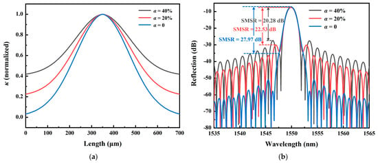
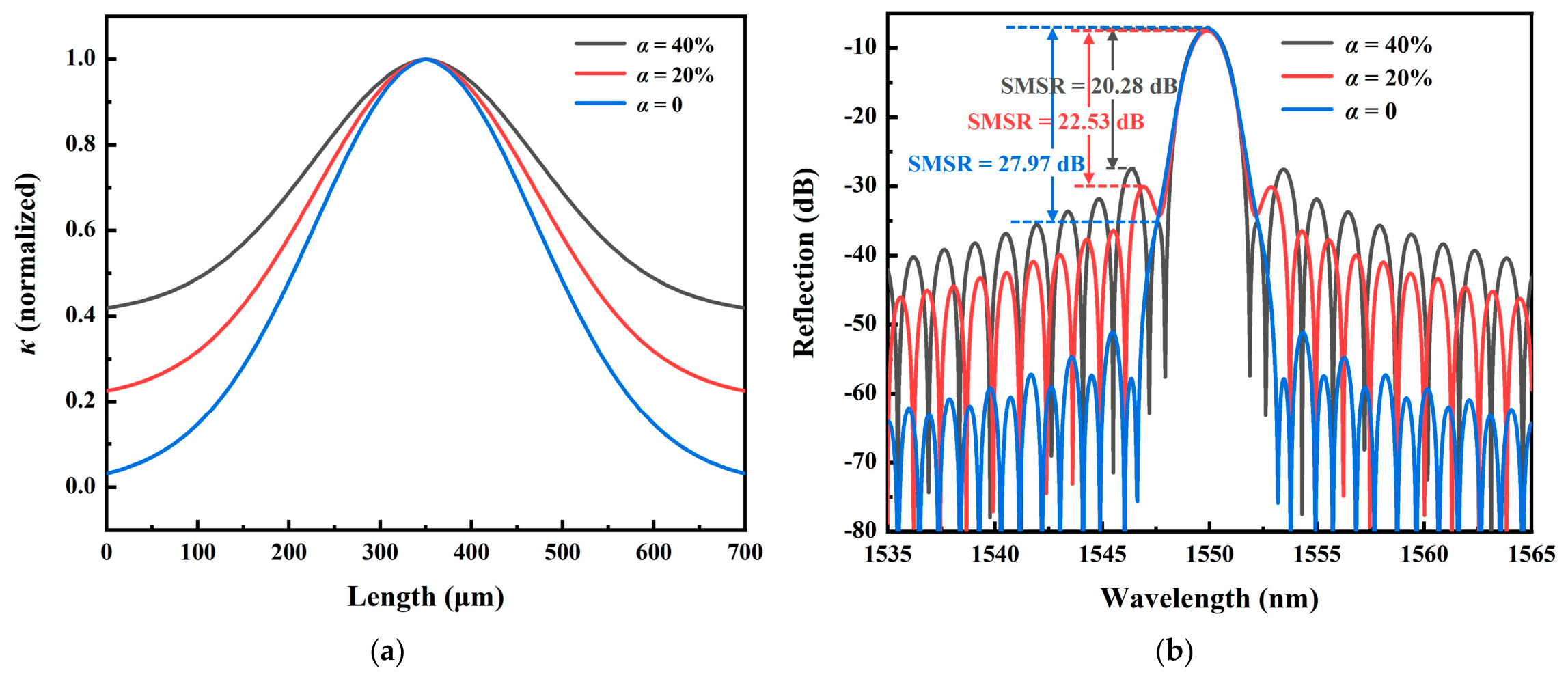
Combining Equations (4) and (5), based on coupled-mode theory and the transfer matrix method, the influence of κmin on the spectrum of the composite apodized FBG was simulated. The constraint coefficient α is defined as the ratio of κmin to κmax. Figure 1a shows the variation profiles of the coupling strength under composite apodization with different α values. It can be seen that at the three values of 40%, 20%, and 0, the coupling strength at both edges gradually decreases. Figure 1b presents the simulated reflection spectra of the composite apodized FBGs under different α values. At the three values of 40%, 20%, and 0, the SMSRs of the composite apodized FBGs with similar reflectivity are 20.28 dB, 22.53 dB, and 27.97 dB, respectively. Compared with α = 40%, the SMSR of the composite apodized FBG is improved by 2.25 dB and 7.69 dB under α = 20% and α = 0, respectively. The calculation results confirm that the smaller the α value, the greater the improvement in the SMSR. In addition, the −3 dB bandwidths of the three reflection spectra are essentially the same, all approximately 1.6 nm. Therefore, applying edge constraints to the composite apodized FBG to further reduce the minimum coupling strength at both edges can suppress the side-lobe intensity to a greater extent, thereby achieving the goal of enhancing the SMSR while expanding the bandwidth.
Figure 1.
(a) The variation profiles of the coupling strength under composite apodization with different α values. (b) The simulated reflection spectra of the composite apodized FBGs under different α values.
2.2. Methods
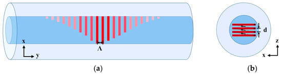
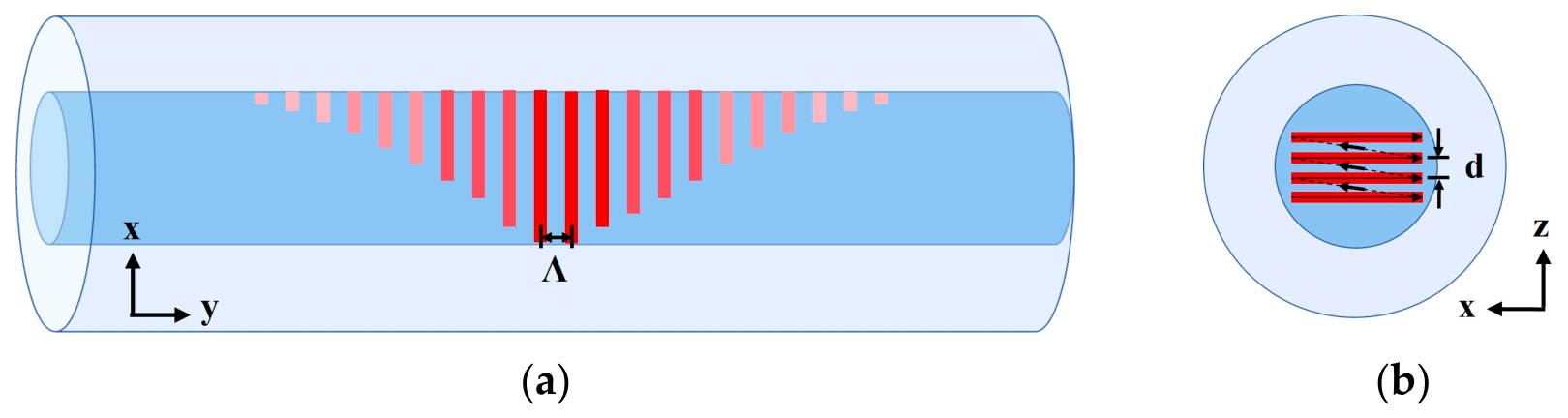
In composite apodization, the writing energy at the FBG edges is the smallest, yielding the lowest coupling strength. To further constrain the coupling strength at the edges, we shifted the writing positions toward the fiber core edges while controlling the position and length of the writing lines. Figure 2 illustrates the writing method for femtosecond laser edge-constrained composite apodization, with the trajectories in the x-y plane and x-z plane shown in Figure 2a and Figure 2b, respectively. Since the four-layer line-by-line method has been demonstrated to maximize the bandwidth expansion of FBGs compared with the point-by-point method and the line-by-line method [19], only this case is discussed here. The length of the writing lines varies according to the function G(y). The minimum line length is 1 μm, the maximum is 7 μm, the line period is 1.071 μm, and the layer spacing is 1.5 μm. The lines are written layer by layer from bottom to top at a speed of 0.05 mm/s. The writing optical setup is consistent with that in reference [19], where a spatial light modulator loaded with grayscale phase patterns is used to modulate the writing pulse energy so that it varies according to the function B(y). Compared with composite apodization, the value of α is smaller after applying edge constraints, thus yielding a higher SMSR. A femtosecond laser with a wavelength of 515 nm and a pulse duration of 290 fs is employed, emitting linearly polarized light in the horizontal direction. The maximum repetition frequency of the laser is 200 kHz. A focusing objective (50×, NA = 0.42) is used to focus the beam into the core of an optical fiber, which is a germanium-doped single mode silica fiber with a core diameter of 8.2 µm and a cladding diameter of 125 µm.
Figure 2.
Writing method of femtosecond laser edge-constrained composite apodization: (a) Trajectories in the x-y plane. (b) Trajectories in the x-z plane.
3. Results and Discussions
3.1. Inscribing Results of ECAFBG
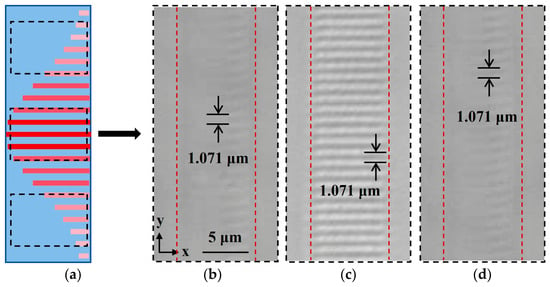
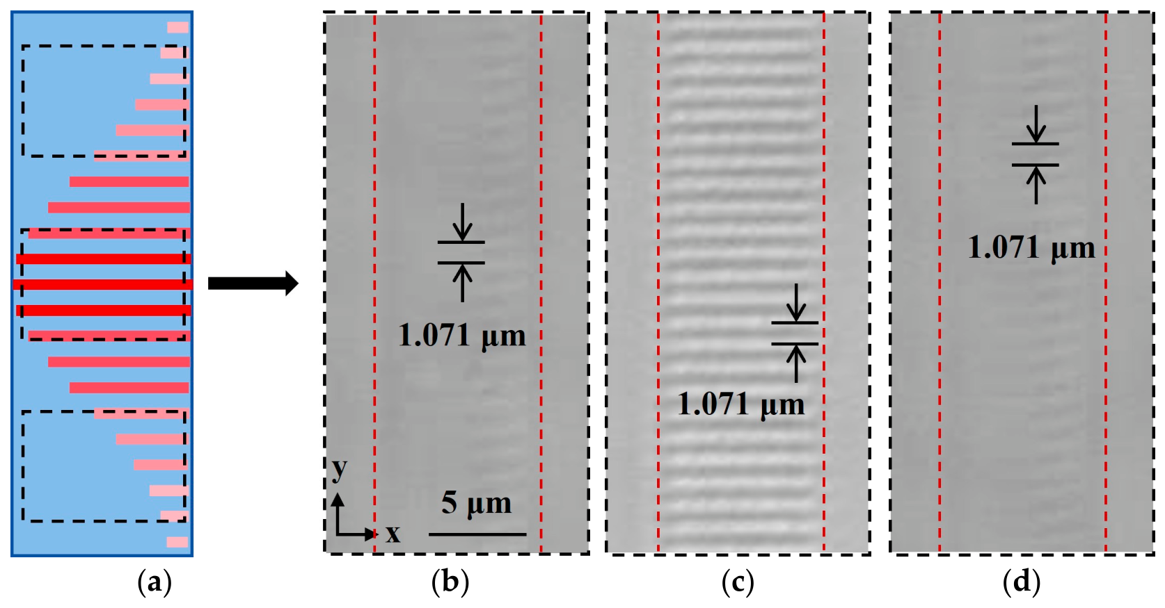
Figure 3 shows the schematic diagram and microscopic images of the traces inscribed by the edge-constrained composite apodization method. The area marked by the red dotted line in Figure 3b–d is the core of the optical fiber. The length of the ECAFBG is approximately 0.7 mm. The writing traces at both edges are relatively shallow and located close to the fiber core edges, so as to achieve constraints on the coupling strength. The writing traces in the middle are relatively deep and essentially occupy the entire fiber core. The writing pulse energy reaches its maximum at the middle position, at approximately 16 nJ.
Figure 3.
The traces inscribed by the edge-constrained composite apodization method. (a) Schematic diagram. (b) Microscopic images at one edge of fiber core. (c) Microscopic images at middle of fiber core. (d) Microscopic images at another edge of fiber core.
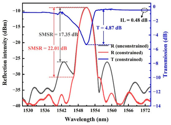
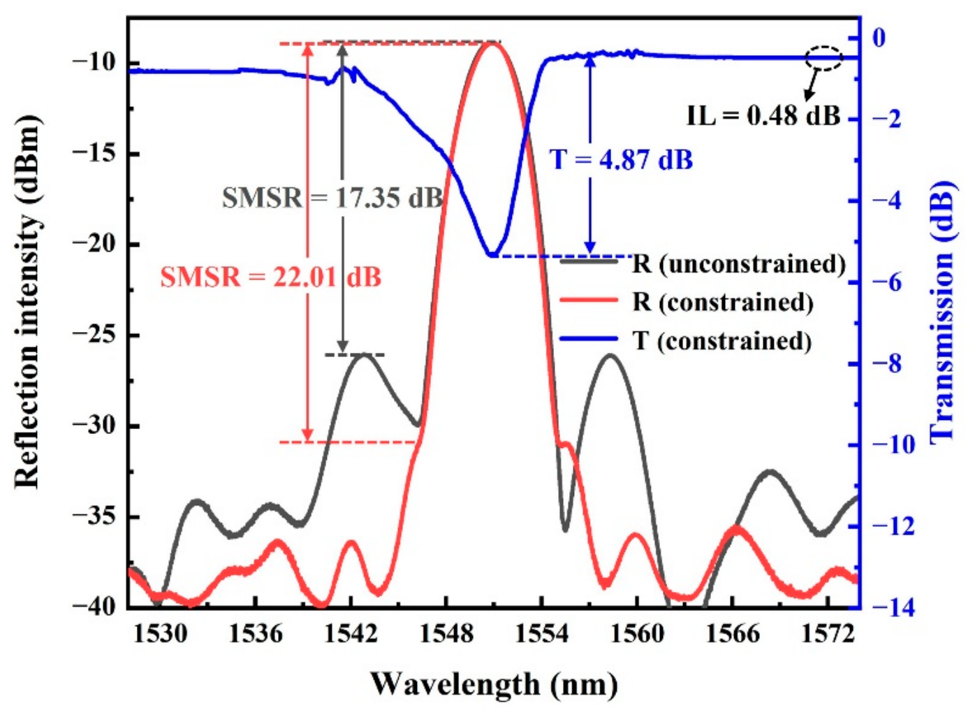
Figure 4 shows the reflection and transmission spectra of the multilayer line-by-line composite apodized FBG under edge constraints, along with the reflection spectrum of the multilayer line-by-line composite apodized FBG without edge constraints for comparison. All reflection spectra have similar reflectivity. The SMSR of the composite AFBG is 17.35 dB without edge constraints, whereas it reaches 22.01 dB with edge constraints, an improvement of approximately 4.7 dB. The −3 dB bandwidths of the two cases show no significant change, both being approximately 3.7 nm. In addition, the transmission loss of the composite apodized FBG under edge constraints reaches approximately 4.87 dB, indicating good reflectivity, and its insertion loss (IL) is approximately 0.48 dB. The inscribing results demonstrate that the composite apodized FBG with edge constraints can achieve a higher SMSR while essentially not affecting the bandwidth and reflectivity, thereby further improving the spectrum of the composite apodized FBG.
Figure 4.
The spectra of the multilayer line-by-line composite apodized FBG with and without edge constraints.
Both ends of the composite apodized FBG under edge constraints have the shortest line length and minimum pulse energy, are located at the core edge, and therefore have the minimum edge constraint coefficient α. Based on the setting of the writing parameters and comparison with other related inscription results, we can estimate that α in the experiment is roughly in the range of 10–20%. Direct experimental calibration of α is beyond the scope of this paper and is left for subsequent research. In inscription, the lower bound of α is subject to practical factors and cannot be 0 as in the ideal case, such as the finite line length and cross-section required for effective inscription, the refractive index modulation threshold of the material, and the finite dynamic range and quantization step of the spatial light modulator. Therefore, α in the practical inscription of composite apodized FBG under edge constraints is the achievable lower bound, which can yield a relatively large improvement in SMSR.
To verify the repeatability of the proposed method, five separate inscribing experiments were carried out. The statistical results show that the SMSR of the composite AFBG under edge constraints is approximately 21.79 ± 1.09 dB (mean ± standard deviation), indicating good stability. This method has application prospects in laser devices, filtering components, and sensing.
3.2. Intensity Demodulation Application of ECAFBG
The ECAFBG can expand the bandwidth and further increase the SMSR without degrading reflectivity, making it feasible for intensity demodulation. Compared with conventional FBGs, the ECAFBG has a larger linear range, which is affected by bandwidth and SMSR, enabling more stable and effective demodulation.
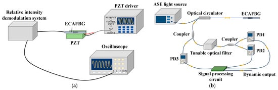
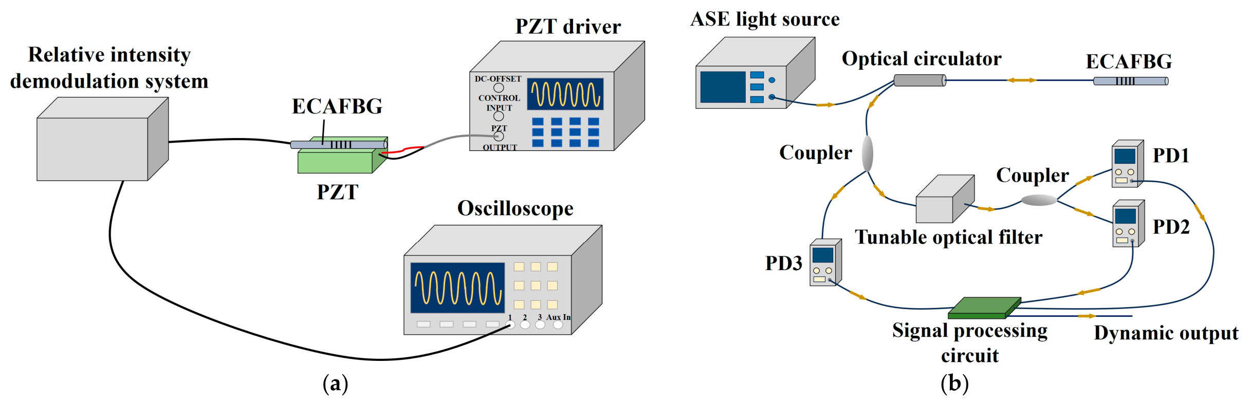
We verified this at room temperature, and the experimental setup is shown in Figure 5a. The inscribed ECAFBG was axially fixed on a piezoelectric ceramic transducer (PZT). A driver was used to generate a sinusoidal voltage signal to drive the PZT, causing it to vibrate periodically and thereby provide an approximately sinusoidal dynamic strain to the ECAFBG. A relative intensity demodulation system developed by our group [24] was connected to the ECAFBG at one end and to an oscilloscope at the other end to display the demodulated signal. The output frequency of the PZT driver was fixed at 50 Hz, and the peak-to-peak driving voltage was increased from 10 V to the maximum value allowed by the PZT of 150 V in steps of 20 V. The waveform and peak-to-peak value of the output signal of the demodulation system were recorded. Figure 5b shows the schematic diagram of the relative intensity demodulation system. The light source adopts a flat-top amplified spontaneous emission (ASE) source, with an emission wavelength range of 1525–1566 nm and an output power of 20 mW. The light emitted by the ASE source is injected into the ECAFBG through an optical circulator, and its reflected light is split into two paths by a 10:90 fiber coupler: the 90% path enters a Fabry–Pérot tunable optical filter, and after filtering is equally divided into two beams by a 50:50 coupler, which are received by photodetector 1 (PD1) and PD2, respectively; the 10% path is directly received by PD3 as the reference light intensity. For signal processing, the PD1 output is sampled at 10 Hz after passing through a low-pass filter with a 10 Hz cutoff frequency, and is ratioed with the PD3 reference value to serve as the reference for 3 dB point locking. A self-developed signal processing circuit board controls a high-precision digital-to-analog converter to generate the control voltage for the tunable optical filter, so the filter center wavelength is always locked to the true 3 dB point of the ECAFBG. The circuit board synchronously acquires the real-time ratio of PD2 to PD3 at a high sampling rate of 1 MHz and outputs it directly as the demodulation result of the dynamic strain signal. The demodulation output is connected to an oscilloscope for observation and recording. This scheme eliminates the influence of common-mode optical power fluctuations and, with a feedback loop, keeps the filter center wavelength in the optimal linear region, thereby stably extracting dynamic signals.
Figure 5.
(a) Experimental equipment for intensity demodulation of ECAFBG. (b) Schematic diagram of the relative intensity demodulation system.
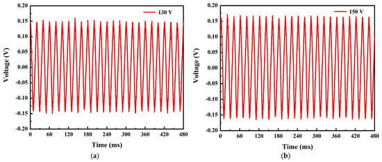
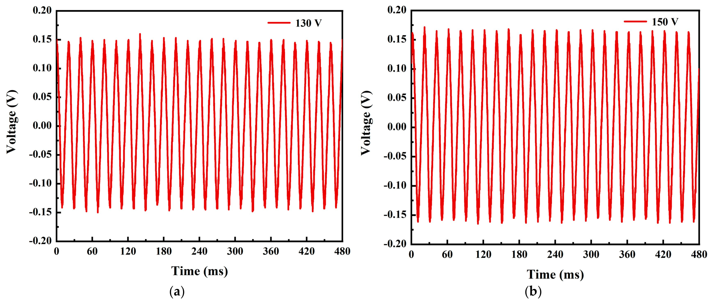
Figure 6 shows the output waveforms obtained under the intensity demodulation. Due to space limitations, only the demodulation results at driving voltages of 130 V and 150 V are selected here for representative presentation. As the PZT driving voltage gradually increases, the strain amplitude applied to the FBG also increases accordingly. The experimental results show that, under the condition that the PZT output frequency is set to 50 Hz, when the intensity demodulation method is used to demodulate the signal from the ECAFBG, a sinusoidal signal can still be successfully demodulated even when a full-scale driving voltage of 150 V is applied to the FBG, and sinusoidal signals with good waveform quality and small distortion can be obtained over the entire demodulation range.
Figure 6.
The output waveforms obtained under the intensity demodulation: (a) 130 V; (b) 150 V.
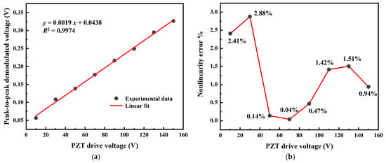
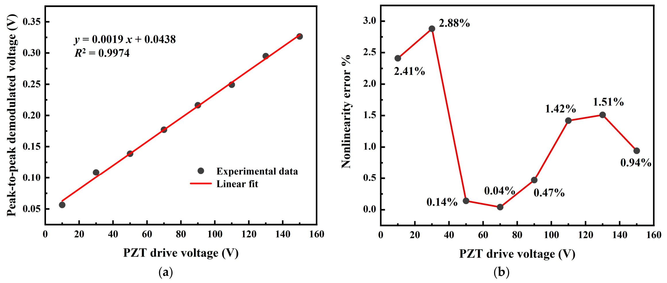
In addition, a linear fit was performed on the peak-to-peak value of the demodulated voltage, and the fitting results are shown in Figure 7a. As the PZT driving voltage increases, the peak-to-peak value of the demodulated voltage exhibits a good linear growth trend, with a linear fitting coefficient R2 of 0.9974. Figure 7b shows the nonlinearity errors at each test point, which are 2.41%, 2.88%, 0.14%, 0.04%, 0.47%, 1.42%, 1.51%, and 0.94%, respectively. The maximum nonlinearity error is 2.88%. Due to the inherent hysteresis effect of the PZT, this nonlinearity error is essentially the result of the superposition of the PZT hysteresis effect and the nonlinearity of the demodulation system, and the measured nonlinearity error may exceed the inherent error of the demodulation system itself [24]. The experimental results demonstrate that the ECAFBG can achieve relatively stable dynamic strain measurement over a large range in intensity demodulation. The dynamic strain experiment in this paper is intended to demonstrate a potential application of the ECAFBG in intensity demodulation, and the 50 Hz excitation frequency is limited by the PZT driver used in our laboratory. For an actual FBG sensor, its frequency response depends mainly on the connection method between the FBG and the measured component, such as the strain transfer coefficient of the adhesive layer, rather than on the grating itself. A systematic study of the frequency response of packaged ECAFBG sensors will be carried out in our future work.
Figure 7.
Intensity demodulation linearity experiment. (a) Linear fitting. (b) Nonlinearity errors.
4. Conclusions
In this paper, a femtosecond laser edge-constrained composite apodization method was proposed to simultaneously enhance the bandwidth and SMSR of FBGs. Building on multilayer composite apodization, this method shifts the writing positions toward the fiber core edges while simultaneously controlling the position and length of the writing lines, thereby imposing constraints on the coupling strength at both edges of the FBG to achieve a lower edge coupling strength, which in turn enhances the SMSR while expanding the bandwidth. Simulations of the spectra of composite apodized FBGs with different edge constraints were carried out. The calculation results show that, after applying edge constraints, the smaller the edge coupling strength, the more significantly the SMSR is improved, while the bandwidth and reflectivity remain essentially unchanged. A four-layer composite apodized FBG was inscribed at the fiber core edges. The experimental results demonstrate that, after applying edge constraints, the SMSR of the fabricated composite apodized FBG is improved by approximately 4.7 dB, the −3 dB bandwidth is approximately 3.7 nm, and the transmission loss reaches approximately 4.87 dB, still exhibiting good reflectivity, with an insertion loss of approximately 0.48 dB. Compared with the composite apodized FBG without constraints, it maintains a relatively wide bandwidth and good reflectivity. Its length is only 0.7 mm, which is difficult to achieve with other writing methods. The method also exhibits good repeatability. The proposed ECAFBG was tested on a PZT, and the signal was demodulated by intensity demodulation. The experimental results show that, at a PZT output frequency of 50 Hz, a sinusoidal signal can still be successfully demodulated even when a full-scale driving voltage of 150 V is applied to the FBG. The peak-to-peak value of the demodulated voltage exhibits a good linear growth trend with the driving voltage, with a maximum nonlinearity error of 2.88%. The results demonstrate that the ECAFBG is capable of dynamic strain measurement over a relatively large range. The proposed method provides an effective approach for simultaneously achieving short-length FBGs with wide bandwidth and high SMSR. In addition to its application in intensity demodulation, this method holds potential application prospects in compact laser devices and sensing devices.
Author Contributions
Conceptualization, J.W. and N.Y.; methodology, N.Y. and H.-Y.W.; software, N.Y.; validation, J.W. and N.Y.; formal analysis, J.W.; investigation, J.W.; resources, P.-G.J. and H.-Y.W.; data curation, J.W.; writing—original draft preparation, J.W. and N.Y.; writing—review and editing, J.W.; visualization, Q.-Y.R. and J.-J.Y.; supervision, P.-G.J.; funding acquisition, Q.-Y.R. and J.-J.Y. All authors have read and agreed to the published version of the manuscript.
Funding
This research was funded by National Natural Science Foundation of China, grant number 52505617; the China Postdoctoral Science Foundation, grant number 2025M780801; and the Fundamental Research Program of Shanxi Province, grant number 202403021212020.
Data Availability Statement
The original contributions presented in this study are included in the article. Further inquiries can be directed to the corresponding authors.
Conflicts of Interest
The authors declare no conflicts of interest.
References
- He, J.; Xu, B.; Xu, X.; Liao, C.; Wang, Y. Review of Femtosecond-Laser-Inscribed Fiber Bragg Gratings: Fabrication Technologies and Sensing Applications. Photonic Sens. 2021, 11, 203–226. [Google Scholar] [CrossRef] [Scilit]
- Tosi, D. Review of Chirped Fiber Bragg Grating (CFBG) Fiber-Optic Sensors and Their Applications. Sensors 2018, 18, 2147. [Google Scholar] [CrossRef] [Scilit] [PubMed]
- Zhang, J.; Zhao, Q.; Du, D.; Zhu, Y.; Zheng, S.; Chen, D.; Cui, J. High flexibility FBG inscribing by point-by-point method via femtosecond laser: Technology, progress, and challenges. Mater. Today Commun. 2024, 39, 108760. [Google Scholar] [CrossRef] [Scilit]
- Baba, T.; Saidin, N.; Hasbullah, N.F.; Ahmad, I. Radiation tolerant fiber Bragg gratings: Review of FBG sensing. J. Opt. 2025, 1–14. [Google Scholar] [CrossRef] [Scilit]
- Feng, W.; Gu, Z. Ultra-Broadband Optical Filter Based on Chirped Long-Period Fiber Grating and PMTP. IEEE Photonics Technol. Lett. 2018, 30, 1361–1363. [Google Scholar] [CrossRef] [Scilit]
- Zhu, C.; Zhao, H.; Wang, P.; Subramanian, R.; Li, H. Enhanced Flat-Top Band-Rejection Filter Based on Reflective Helical Long-Period Fiber Gratings. IEEE Photonics Technol. Lett. 2017, 29, 964–966. [Google Scholar] [CrossRef] [Scilit]
- Ali, T.A.; Shehata, M.I.; Mohamed, N.A. Design and performance investigation of a highly accurate apodized fiber Bragg grating-based strain sensor in single and quasi-distributed systems. Appl. Opt. 2015, 54, 5243–5251. [Google Scholar] [CrossRef] [Scilit] [PubMed]
- Zou, M.; Shen, K.; Song, Q.; Dai, Y.; Xiao, X.; Sun, Q.; Yan, Z. Sub-kHz-linewidth laser generation by self-injection locked distributed feedback fiber laser. Opt. Laser Technol. 2024, 169, 110022. [Google Scholar] [CrossRef] [Scilit]
- Cheng, X.P.; Zhang, J.; Shum, P.; Tang, M.; Wu, R.F. Influence of Sidelobes on Fiber-Bragg-Grating-Based $Q$-switched Fiber Laser. IEEE Photonics Technol. Lett. 2007, 19, 1646–1648. [Google Scholar] [CrossRef]
- Fan, Y.; Bao, W.; Liao, C.; Wang, Y. Chirped and tilted fiber Bragg gratings inscribed by femtosecond laser direct writing technology. In Proceedings of the Fourteenth International Conference on Information Optics and Photonics (CIOP 2023), Xi’an, China, 7–10 August 2023. [Google Scholar]
- Mandal, H.N.; Sidhishwari, S. Apodized long period grating and sensitivity analysis of high order resonant wavelengths for temperature measurement. Appl. Phys. B 2025, 131, 42. [Google Scholar] [CrossRef] [Scilit]
- Li, X.; Duan, T.; Wang, R.; Chen, F.; Qiao, X. Ultrahigh return loss LPFGs fabricated via femtosecond laser direct writing of ultrashort TFBGs. Opt. Lett. 2025, 50, 2053–2056. [Google Scholar] [CrossRef] [Scilit] [PubMed]
- Koptev, M.Y.; Zapryalov, A.E.; Wolf, A.A.; Lipatov, D.S.; Likhachev, M.E.; Muravyev, S.V.; Kim, A.V. Chirped fiber Bragg gratings directly inscribed by a femtosecond laser in an ytterbium-doped fiber for spectrum recovery, loss compensation and effective use in a CPA scheme. Opt. Laser Technol. 2025, 181, 111989. [Google Scholar] [CrossRef] [Scilit]
- Pan, X.-P.; Guo, Q.; Wu, Y.-D.; Liu, S.-R.; Wang, B.; Yu, Y.-S.; Sun, H.-B. Femtosecond laser inscribed chirped fiber Bragg gratings. Opt. Lett. 2021, 46, 2059–2062. [Google Scholar] [CrossRef] [Scilit] [PubMed]
- Qu, H.; Chen, Z.; Gao, S.; Min, R.; Woyessa, G.; Bang, O.; Wang, H.; Caucheteur, C.; Hu, X. Femtosecond laser line-by-line tilted Bragg grating inscription in single-mode step-index TOPAS/ZEONEX polymer optical fiber. Opt. Lett. 2023, 48, 1438–1441. [Google Scholar] [CrossRef] [Scilit] [PubMed]
- Fan, Y.; Bao, W.; Fu, C.; Liao, C.; Wang, Y. Broadband and High-Filtering-Efficiency Band-Rejection Filters Fabricated Using Femtosecond Laser Line-by-Line Technology. J. Light. Technol. 2025, 43, 7847–7853. [Google Scholar] [CrossRef] [Scilit]
- Becker, M.; Chiamenti, I.; Elsmann, T.; Chernysheva, M. Short Broadband Fiber Gratings With Low Group Delay. J. Light. Technol. 2021, 39, 2956–2960. [Google Scholar] [CrossRef] [Scilit]
- Raja, S.V.; Govindarajan, A.; Mahalingam, A.; Lakshmanan, M. Tailoring inhomogeneous $\mathcal{PT}$-symmetric fiber-Bragg-grating spectra. Phys. Rev. A 2020, 101, 033814. [Google Scholar] [CrossRef] [Scilit]
- Yang, N.; An, G.; Wang, Y.; Wang, J.; Wang, H.; Yang, J.; Jia, P. Femtosecond laser multi-layer composite apodization technique to expand the bandwidth of fiber Bragg gratings. Opt. Express 2026, 34, 6978–6992. [Google Scholar] [CrossRef] [Scilit] [PubMed]
- Guo, Q.; Zheng, Z.; Wang, B.; Pan, X.; Liu, S.; Tian, Z.; Chen, C.; Yu, Y. Femtosecond Laser Fabricated Apodized Fiber Bragg Gratings Based on Energy Regulation. Photonics 2021, 8, 110. [Google Scholar] [CrossRef] [Scilit]
- He, J.; Chen, Z.; Xu, X.; He, J.; Xu, B.; Du, B.; Guo, K.; Chen, R.; Wang, Y. Femtosecond laser line-by-line inscription of apodized fiber Bragg gratings. Opt. Lett. 2021, 46, 5663–5666. [Google Scholar] [CrossRef] [Scilit] [PubMed]
- Hua, Y.; Guan, M.; Chen, H.; Niu, F.; Miao, Y.; Cai, Z.; Chen, M.; Zhao, C.; Liao, C. Apodized fiber Bragg grating inscribed by femtosecond laser point-by-point method. In Proceedings of the Third International Computing Imaging Conference (CITA 2023), Sydney, Australia, 1–3 June 2023. [Google Scholar]
- Su, J.; Jia, P.; An, G.; Wang, H.; Wang, J.; Wang, H.; Qin, L.; Xiong, J. Edge-weak-coupling femtosecond laser line-by-line inscription technique for fabricating apodized FBG. Opt. Laser Technol. 2024, 175, 110719. [Google Scholar] [CrossRef] [Scilit]
- Ren, Q.; Zhuang, Z.; Dai, Y.; An, G.; Wang, H.; Liu, J.; Jia, P. Active tracking and locking demodulation technique based on relative intensity of vibration-temperature dual parameters in high-temperature fiber optic FBG vibration sensors. Laser Optoelectron. Prog. 2026, 64, 0306010. (In Chinese) [Google Scholar]
Disclaimer/Publisher’s Note: The statements, opinions and data contained in all publications are solely those of the individual author(s) and contributor(s) and not of MDPI and/or the editor(s). MDPI and/or the editor(s) disclaim responsibility for any injury to people or property resulting from any ideas, methods, instructions or products referred to in the content. |
© 2026 by the authors. Licensee MDPI, Basel, Switzerland. This article is an open access article distributed under the terms and conditions of the Creative Commons Attribution (CC BY) license.