


Abstract
To address the challenges of low precision, slow convergence, and poor anti-interference in traditional Particle Swarm Optimization (PSO) for Permanent Magnet Synchronous Motor (PMSM) speed control, a new Adaptive Hybrid Particle Swarm Optimization (AM-PSO) algorithm is proposed. This algorithm integrates adaptive dynamic inertia weight, hybrid local search mechanisms, neural network-based adjustments, multi-stage optimization, and multi-objective optimization. The adaptive dynamic inertia weight improves the balance, boosting both convergence speed and accuracy. The inclusion of Simulated Annealing (SA) and Differential Evolution (DE) strengthens local search and avoids local optima. Neural network adjustments improve search flexibility by intelligently modifying search direction and step size. Additionally, the multi-stage strategy allows broad exploration initially and refines local searches as the solution approaches, speeding up convergence. The multi-objective optimization further ensures the simultaneous improvement of key performance metrics like precision, response time, and robustness. Experimental results demonstrate that AM-PSO outperforms traditional PSO in PMSM speed control, achieving a 40% reduction in speed error, 25% faster convergence, and enhanced robustness. Notably, the speed error increased only marginally from 0.03 RPM to 0.05 RPM, showcasing the algorithm’s superior ability to reject disturbances.
1. Introduction
Permanent Magnet Synchronous Motors (PMSMs) are widely used in various modern applications, including industrial drives, robotics, electric vehicles, and renewable energy systems, due to their high efficiency, reliability, and precise control capabilities [1]. These motors are particularly favored for their ability to provide excellent performance in high-torque and high-speed operations. However, achieving precise control of PMSM speed remains a significant challenge due to the inherent non-linear dynamics, variations in motor parameters, and external disturbances that often occur during operation [2]. Accurate speed regulation is crucial in applications where precise motor control directly impacts system performance and energy efficiency [3].
PID controllers are commonly used for PMSM speed regulation [4]. PID controllers are straightforward to implement and cost-effective, but they often struggle to deliver the desired performance under varying load conditions and external disturbances [5]. In particular, traditional PID controllers face issues related to slow response, poor robustness, and sensitivity to parameter variations. These limitations have motivated researchers to explore alternative optimization techniques to tune PID controllers and improve system performance in PMSM applications [6]. Among the various optimization techniques, Particle Swarm Optimization (PSO) has gained attention due to its ability to solve non-linear optimization problems with relatively low computational complexity.
Traditional PSO is effective but suffers from slow convergence and premature local optima. It also performs poorly in high-dimensional tasks [7]. To address these challenges, numerous modifications and enhancements to the PSO algorithm have been proposed. For instance, Belmadani et al. [8] designed an improved PSO with adaptive factor selection for maximum power point tracking (MPPT) control in photovoltaic systems, which enhanced the algorithm’s adaptability to environmental changes and improved optimization stability. Kabra and Rani [9] conducted a comparative study of P&O and PSO-based MPPT controllers under partial shading conditions, verifying that PSO exhibits superior global search capability and convergence speed in nonlinear system optimization. Liu et al. [10] introduced an arctangent function-based learning factor to improve the PSO algorithm’s ability to escape local optima in motor control applications. However, while this method improves the balance between exploration and exploitation, it still struggled to provide a satisfactory trade-off between convergence speed and precision. Amini et al. [11] proposed the IMF optimization algorithm, which updates particle positions based on fitness values. While this approach improved the convergence speed, it remained susceptible to local optima.
In the specific field of PMSM speed control, PSO-based parameter optimization has become a research focus. Zhang et al. [12] proposed an adaptive PSO algorithm for robust speed control of PMSMs under parameter uncertainties, and experimental results showed that the algorithm effectively reduces speed fluctuation caused by parameter variations. Raj et al. [13] used a modified PSO to tune PID controller parameters for PMSM speed regulation, achieving faster response time and lower overshoot compared with traditional manual tuning methods. Other approaches, such as those by Xue et al. [14], combined PSO with sliding-mode chaotic controllers to address chaotic behavior in motors, while Wang et al. [15] proposed a Gaussian-based improved PSO algorithm for automatically tuning weighting factors in model predictive control, effectively lowering switching frequency while preserving steady-state performance. Reda et al. [16] proposed an MFPSO hybrid algorithm for efficient PID tuning in 4WD DC-motor systems, greatly improving speed control performance over existing methods. However, the introduction of fuzziness led to a decrease in computational efficiency, limiting their applicability in real-time systems.
Notably, external disturbances and parameter mismatches are critical factors affecting PMSM control performance. Cai et al. [17] proposed a predefined-time sliding mode control strategy combined with an exact time disturbance observer for second-order systems, emphasizing that disturbance suppression is essential for improving control precision and robustness. However, existing PSO-based control methods for PMSMs rarely integrate adaptive disturbance compensation mechanisms and multi-stage optimization strategies, leading to insufficient balance between convergence speed, optimization accuracy, and anti-disturbance capability under complex working conditions.
In response to the limitations of traditional PSO and PID control methods, this paper proposes an Adaptive Hybrid Particle Swarm Optimization (AM-PSO) algorithm to improve the performance of PMSM speed control. AM-PSO integrates several advanced optimization techniques to address common issues such as slow convergence and local optima. A key feature is the dynamic adjustment of the inertia weight, which allows the algorithm to adapt to different stages of the optimization process, striking a balance between exploration and exploitation. This enhances convergence speed and solution accuracy. Additionally, AM-PSO incorporates local search strategies like Simulated Annealing (SA) and Differential Evolution (DE), which improve the search efficiency and prevent the algorithm from getting trapped in suboptimal solutions. Furthermore, a multi-stage optimization approach ensures broad exploration in the initial stages, followed by more focused local searches as the solution nears optimality. Lastly, the algorithm employs multi-objective optimization to simultaneously optimize multiple performance metrics, including control precision, response time, and robustness, making it highly suitable for real-time PMSM speed control.
The main contributions of this work include the following:
- 1.
- Adaptive dynamic inertia weight: Adjusts based on the optimization stage, improving convergence and solution accuracy.
- 2.
- Hybrid local search strategies: Incorporates SA and DE to strengthen local search capabilities and prevent premature convergence to suboptimal solutions.
- 3.
- Multi-stage optimization strategy: Enables wide exploration at the beginning and focused local searches close to the optimal solution, speeding up the overall convergence process.
- 4.
- Multi-objective optimization: Optimizes control precision, response time, and system robustness for PMSM speed control, offering a more comprehensive solution.
2. Materials
2.1. Permanent Magnet Synchronous Motor Speed Control
PMSMs are commonly used in applications like electric vehicles and industrial drives because of their high torque density and efficiency [18]. Speed control of PMSMs is crucial for optimizing performance, as it directly impacts energy consumption, system stability, and response time. Achieving precise speed regulation is particularly challenging due to the non-linearities of the motor and varying load conditions, making effective control essential for maintaining optimal operation.
FOC is the most common method used for PMSM speed control, as it decouples torque and flux control, allowing for precise regulation of both [19]. However, fine-tuning control parameters for optimal performance can be complex. Advanced optimization techniques, such as PSO, are increasingly applied to improve the accuracy and robustness of PMSM speed control, addressing issues like system disturbances and non-linear dynamics while ensuring real-time, high-performance operation.
2.2. Mathematical Model in Motor Speed Control
The mathematical model of a motor plays a crucial role in the design and implementation of effective speed control strategies [20]. By representing the motor’s dynamic behavior through equations that describe electrical and mechanical interactions, such models allow for a clear understanding of how input variables, such as voltage and current, affect the motor’s speed and torque. This mathematical representation is essential for developing control algorithms, as it provides the foundation for predicting motor performance under various conditions, enabling precise control over speed regulation.
In particular, for Permanent Magnet Synchronous Motors, accurate mathematical modeling is vital for optimizing control techniques like Field-Oriented Control. The model typically includes equations that govern the motor’s electrical dynamics, such as stator voltage equations, and mechanical dynamics, such as rotor speed and torque relationships. Using this model, control algorithms can be tuned to compensate for disturbances, parameter variations, and non-linearities in the motor, ensuring stable and efficient operation across different load conditions [21]. This makes the mathematical model an indispensable tool for high-performance motor control systems.
2.3. Control System Stability and Performance Analysis
Ensuring stability and optimal performance is critical in motor speed control. Stability refers to the system’s ability to return to the desired condition after disturbances. We analyze stability using methods like Lyapunov stability, Bode plots, and root locus, which help determine whether the system will oscillate, diverge, or stabilize at the desired operating point [22]. These techniques are essential for evaluating system behavior under varying conditions.
Performance metrics such as response time, settling time, overshoot, and steady-state error assess the effectiveness of the control system. The goal is to minimize these metrics while maintaining stable operation [23]. Advanced optimization methods, like PSO, are used to fine-tune control parameters, balancing stability with high-performance criteria. This allows for precise speed regulation while ensuring robustness against disturbances and parameter variations.
Stability performance is measured using three key metrics: settling time, overshoot, and steady-state speed error drift. Settling time measures how quickly the system stabilizes after a disturbance, overshoot quantifies transient behavior, and steady-state error drift evaluates long-term speed consistency. The system exhibits fast settling times, with overshoot remaining below 5%, indicating stable operation. Additionally, the steady-state error drift is kept below 0.02 RPM, demonstrating the robustness of the AM-PSO optimization in maintaining both high performance and stability under various operating conditions.
3. Related Work
3.1. PID Control in PMSM
PID control is commonly used to regulate PMSM speed [24]. The general form of the PID control law is given by
represents the error between the reference speed and the actual motor speed . The control input , typically corresponding to the voltage applied to the motor, is determined by a combination of the proportional term , the integral term , the derivative term , and an additional squared-error term that accounts for accumulated error over time. These terms, along with the squared-error integral , play key roles in minimizing the error and improving the overall response by addressing long-term drift in the error.
The dynamics of a PMSM are described by the following electrical and mechanical equations. The electromagnetic torque produced by the motor is given by
where P is the pole pairs, is the flux, is the q-axis current, L is the inductance, and R is the resistance. The second term represents the effect of the dynamic variation of the current on the torque. The PID controller adjusts the to regulate the motor’s torque, directly influencing its speed.
The voltage equations for the PMSM in the synchronous frame are given by
where and are the d-axis and q-axis voltages, R is the resistance, L is the inductance, and is the rotor speed. The term accounts for the back EMF (electromotive force) in the d-axis and is a correction for dynamic changes in the q-axis current, which influences the flux linkage and voltage. These complex dynamics, controlled by the PID algorithm, regulate the motor’s speed and torque to ensure smooth and efficient operation under varying load conditions.
3.2. PSO-Based PID Optimization for PMSM
Optimizing the PID controller gains for a PMSM is essential for achieving precise speed regulation under varying load conditions [25]. Traditional manual tuning of the PID parameters , , and often leads to suboptimal performance, especially when the motor exhibits nonlinear dynamics or parameter variations. PSO provides a systematic approach to automatically determine the optimal PID parameters by minimizing a predefined performance index. Each particle represents a potential solution and is updated iteratively according to both its individual experience and the global best solution discovered. Particle velocity and position are updated as:
is the inertia factor, and are scaling coefficients, and are uniformly distributed random variables in the range , represents the best individual position of particle k, and denotes the global optimal position. The effectiveness of the particle is assessed using a performance function that combines the tracking error and its rate of change to achieve a rapid response with minimal oscillation.
where and are weighting coefficients that penalize high derivative errors and large deviations. Once the optimal PID parameters are obtained, the control input to the motor is:
which is then used to regulate the q-axis current of the PMSM, directly influencing the electromagnetic torque and rotor speed. The PSO-based approach ensures systematic tuning, significantly improves transient performance, reduces overshoot, and enhances robustness against parameter uncertainties and external disturbances.
3.3. Multi-Objective Optimization in PMSM Control
In practical PMSM control, achieving optimal performance often requires balancing multiple conflicting objectives, such as minimizing speed tracking error, reducing torque ripple, and limiting control effort [26]. MOO provides a systematic framework to address these trade-offs simultaneously. In this context, the design problem can be formulated as the minimization of a vector-valued function:
where represents the integral of squared speed error, is the torque ripple index relative to the average torque , and quantifies the control effort through the squared control input . PMSM control input is given by the standard PID law:
The q-axis current , influencing the electromagnetic torque and speed dynamics. Multi-objective optimization algorithms, such as NSGA-II or Pareto-based PSO, providing a trade-off surface that allows designers to select PID gains based on the relative importance of speed accuracy, torque smoothness, and control effort.
The multi-objective problem can be further compactly represented using a weighted aggregation approach:
where , , and are weighting factors reflecting the designer’s preference among the competing objectives. By adjusting these weights, the optimization can prioritize fast speed response, low torque ripple, or minimal control effort, ensuring a flexible and robust PMSM control design under varying operating conditions.
4. Methodology
4.1. Multi-Objective AM-PSO for PMSM Speed Control
In PMSM speed control, multiple conflicting performance objectives, such as precision, response time, and energy efficiency, need to be optimized simultaneously. AM-PSO addresses these conflicting goals through multi-objective optimization methods. The fitness function for multi-objective optimization is
where are the performance metrics, are their weights, and is a penalty factor for constraint violations.
To guide the optimization, Pareto dominance is used. A solution dominates if it outperforms in at least one objective and is no worse in others. The crowding distance measure is used to maintain diversity:
The particles are ranked using a non-dominated sorting approach. A particle is dominated by if
The solutions are then organized into fronts , with the first front containing the non-dominated particles:
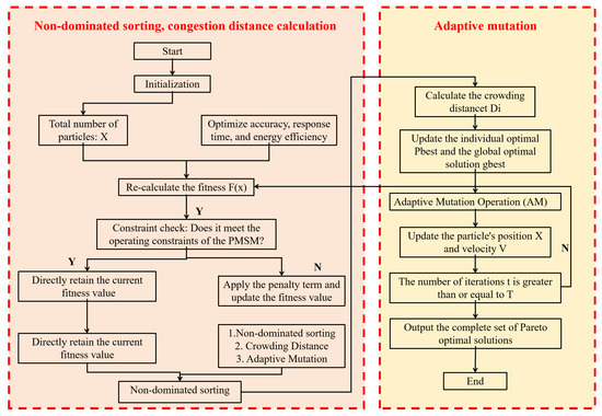
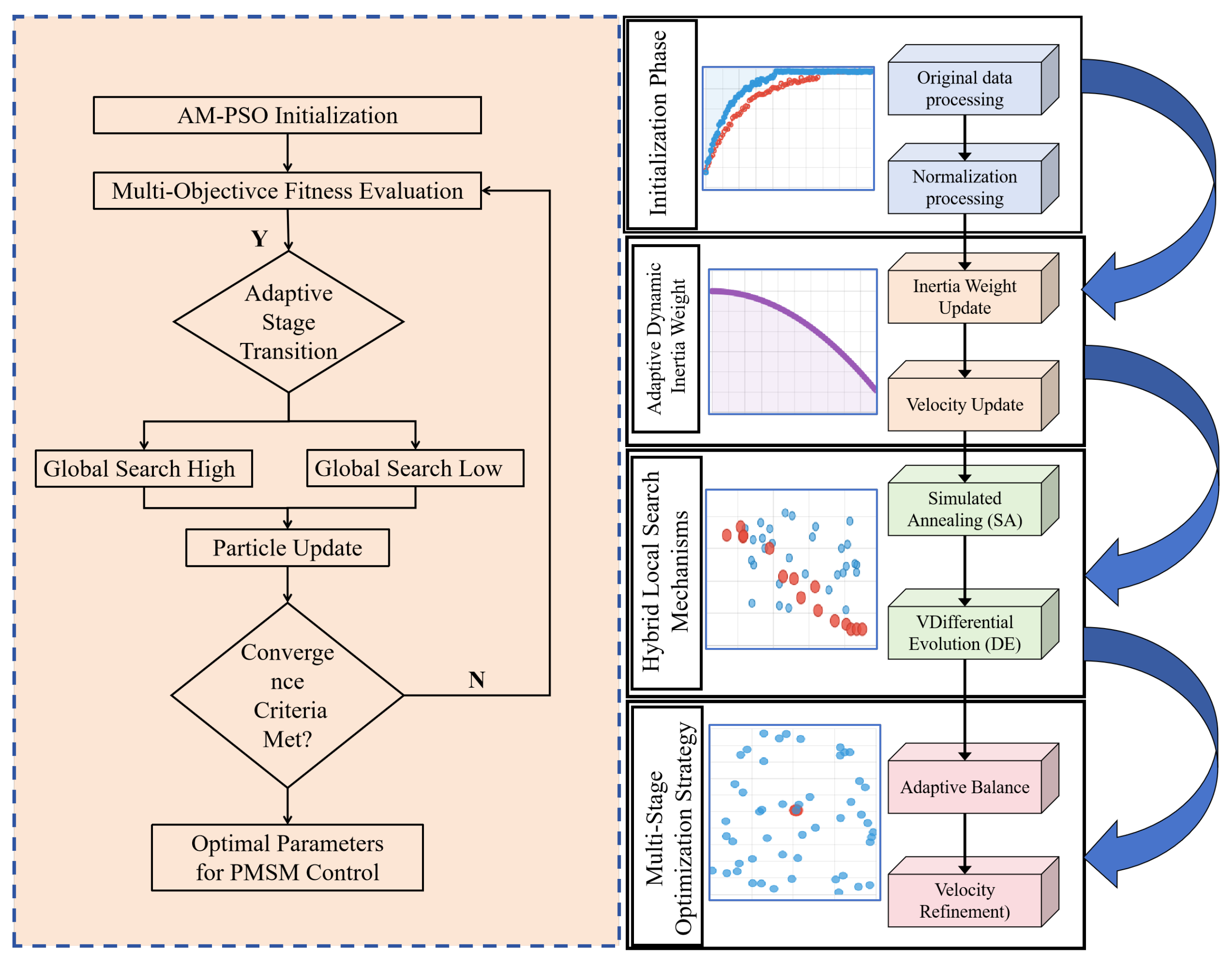
The multi-objective AM-PSO framework is shown in Figure 1, demonstrating how the algorithm balances exploration and exploitation, while optimizing multiple conflicting objectives.
Figure 1.
Dynamic Inertia Weight Adjustment for Enhanced Optimization in AM-PSO.
4.2. Dynamic Inertia Weight Adjustment in Optimization
The Adaptive Dynamic Inertia Weight is crucial in the AM-PSO algorithm, adjusting the trade-off between global search and local refinement. In the initial stages of optimization, a larger inertia weight promotes broader exploration, while in later stages, a smaller inertia weight focuses the search on local exploitation to refine the solution.
The inertia weight is updated dynamically over time, with the following rule:
where and are the maximum and minimum inertia weights, and is the total iterations. This ensures that the inertia weight gradually decreases, allowing the algorithm to transition from global search to local refinement.
Additionally, the velocity update equation for each particle incorporates the adjusted inertia weight, as follows:
where is the velocity of particle j at iteration t, and are the best local and global positions, and are random variables. The dynamic inertia weight helps guide the particles more efficiently towards the optimal solution by adjusting their exploration and exploitation behavior over time. The velocity symbols for the main PSO [27] particles have been unified as throughout the text. The velocity increments for the SA/DE hybrid components remain and to ensure consistency with the algorithm description. The specific process algorithm is shown in Algorithm 1.
| Algorithm 1 Adaptive Dynamic Inertia Weight for AM-PSO (Modified) |
|
4.3. Hybrid Local Search Mechanisms
To enhance the effectiveness of the local search and mitigate the risk of early convergence to suboptimal solutions, the AM-PSO algorithm integrates hybrid local search strategies, SA and DE. These mechanisms enhance the particle velocity update by refining the search process.
SA is applied to introduce randomness into the search process, allowing the algorithm to avoid getting trapped in local minima and search a broader range of solutions. The velocity update due to SA is given by
where is a scaling factor that controls the impact of the SA mechanism, is the best velocity at time t, represents the distance of particle i from the current best solution, is the temperature at time t, which decreases over iterations, and is the maximum allowed distance in the search space. The exponential term ensures that the randomness decreases over time, focusing the search as the algorithm progresses.
DE is used to refine the search by promoting diversity through population-based updates. In DE, the velocity update depends on the difference between two randomly selected particles, which helps explore the solution space more broadly. The velocity adjustment due to DE is expressed as
where F is scaling factor that controls the enhancement of the difference, C is an exploration factor, and are randomly selected particles at iteration t, and represents the current optimal solution. The term motivates the particle to approach the best solution discovered, while the difference between random particles introduces diversity and prevents premature convergence.
The final particle velocity integrates the main PSO update with the SA and DE increments using dynamic weights:
where the weights for the hybrid mechanisms are dynamically adjusted: linearly decreases from 0.4 to 0.1 over iterations, and , balancing random exploration (SA) and directed optimization (DE). This fusion ensures the particle velocity update benefits from both global search diversity and local refinement.
4.4. Multi-Stage Optimization Strategy
The Multi-Phase Optimization Approach is designed to enhance the efficiency of the search process by adapting the exploration-exploitation balance at different stages of the optimization [28]. The algorithm begins with broad exploration of the solution space to identify promising regions, then refines the search progressively towards optimal solutions as the search evolves.
Initially, in the early stages of optimization, the algorithm prioritizes global exploration to cover a wider area of the solution space. As the solution nears optimality, the search shifts towards local exploitation to fine-tune the best solutions found.
The position update rule for the particle during the multi-phase optimization is expressed as
where is a time-dependent parameter that adjusts the exploration-exploitation balance. Initially, is large, favoring exploration, and decreases over time, promoting exploitation. The velocity update at each stage is influenced by both the global best solution and the individual particle’s best position.
Furthermore, the multi-stage strategy is enhanced by a dynamic adjustment of the particle velocity, ensuring that the search becomes more focused as the algorithm progresses. The velocity update in the later stages is adjusted by incorporating a decreasing factor , which refines the search towards the optimal solution:
where is a decreasing factor that ensures the velocity becomes smaller as the search focuses more on local refinement, making the search process more precise over time. The term encourages a more localized search by adjusting the particle’s velocity towards the previous best velocity.
4.5. Overall Algorithm Framework
The multi-phase optimization strategy is designed to adapt the exploration-exploitation balance at different stages of the optimization. Initially, the algorithm focuses on broad exploration, and as it nears optimal solutions, it transitions to local refinement. AM-PSO incorporates multi-objective optimization to handle conflicting performance objectives such as precision, response time, and energy efficiency. The fitness function combining these objectives is given by
where represent the performance metrics (e.g., speed control error, energy consumption, dynamic response), and are their corresponding weights, reflecting the relative importance of each objective.
To further enhance its generalizability and adaptability across different system configurations, the AM-PSO algorithm is implemented with a modular architecture:
- 1.
- Core Optimization Module: Includes dynamic inertia weighting, hybrid SA/DE search, and multi-stage optimization, implemented in platform-agnostic code (C/Python), ensuring no hardware-specific dependencies.
- 2.
- Interface Module: Provides standardized I/O for seamless integration with various controllers (DSP, MCU, FPGA). Only minimal adjustments are required for PWM frequency, sampling rate, and current/voltage feedback.
- 3.
- Fitness Function Module: Allows configurable weighting of multiple objectives (speed error, energy efficiency, settling time), supporting system-specific optimization requirements such as low-latency control for embedded devices or high-precision performance for industrial drives.
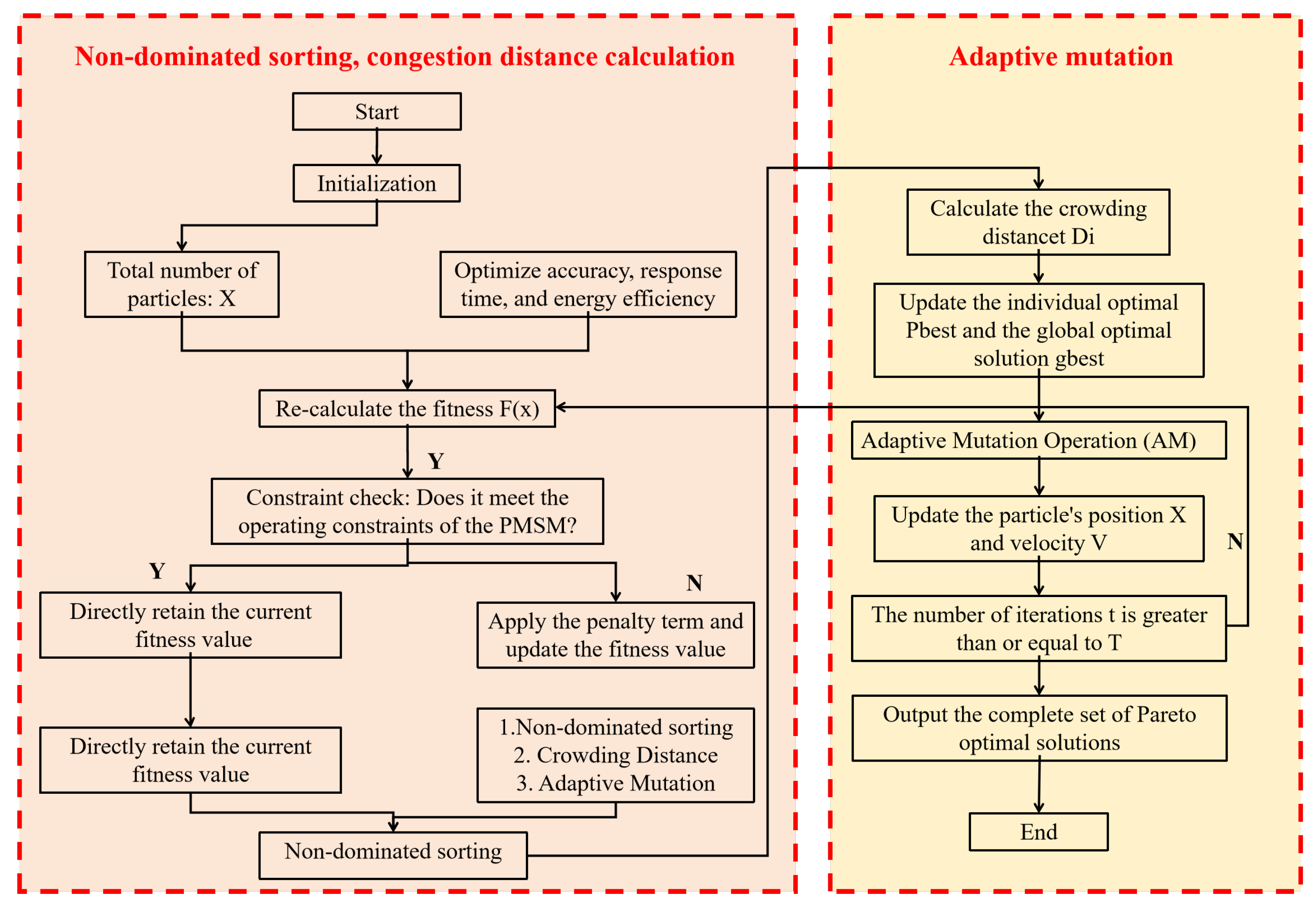
This modular design ensures that AM-PSO can be seamlessly deployed across diverse hardware/software platforms without rewriting the core algorithm, which is validated by cross-configuration experiments (Section 6.6) showing consistent performance across different PMSM setups. AM-PSO balances exploration and exploitation effectively, resulting in improved optimization performance for PMSM speed control. The framework of this multi-objective optimization process is illustrated in Figure 2.
Figure 2.
Overall Framework of the Multi-Objective AM-PSO for PMSM Speed Control.
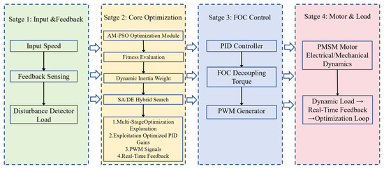
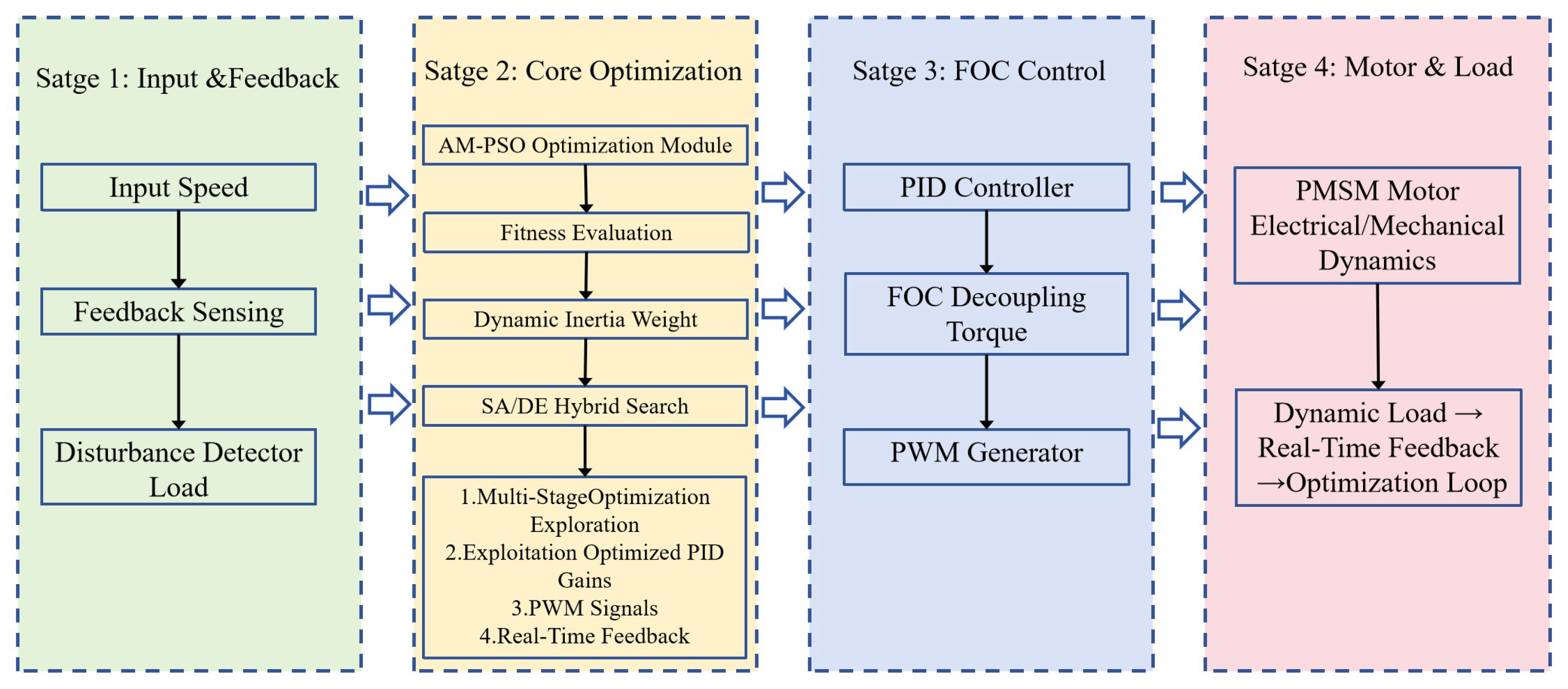
To summarize the steps of the AM-PSO algorithm for PMSM speed control, the following Algorithm 2 is presented. Additionally, a high-level structure of the AM-PSO-based PMSM speed control system with multi-stage optimization is provided in Figure 3. The system is divided into four core stages: (1) Input & Feedback—this stage collects reference speed and real-time motor data, including speed , torque , and motor currents and ; (2) Core Optimization—the AM-PSO algorithm optimizes PID gains using dynamic inertia weight, a hybrid SA/DE search strategy, and a multi-stage approach to balance exploration and exploitation; (3) FOC Control—optimized PID gains are used to generate PWM signals for the motor through torque/flux decoupling; and (4) Motor & Loa—this stage executes the motor’s electrical and mechanical dynamics and simulates the load, providing real-time feedback for the closed-loop optimization. The system’s stages are color-coded for clarity, and arrows in the figure indicate the closed-loop data flow between each stage, illustrating how the process works in a continuous cycle.
| Algorithm 2 AM-PSO Framework for Multi-Objective Optimization |
|
Figure 3.
High-level structure of the AM-PSO-based PMSM speed control system with multi-stage optimization.
5. Experimental Configuration
5.1. Algorithm Setup and Parameters
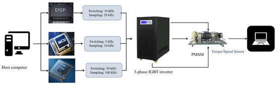
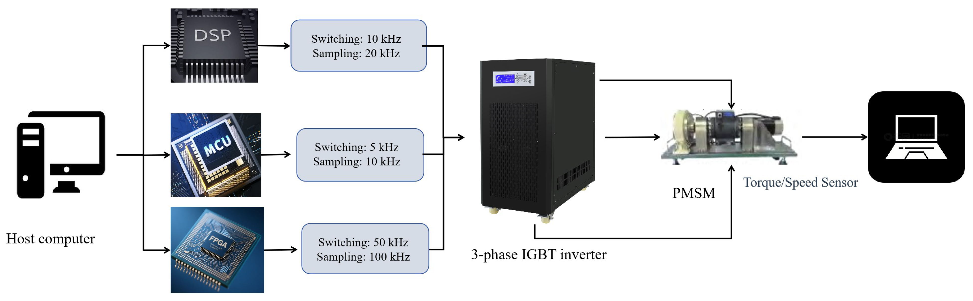
Figure 4 illustrates the experimental setup for PMSM speed control using the AM-PSO algorithm, showing three system configurations—DSP, MCU, and FPGA—each serving as the control unit. Switching frequencies and sampling frequencies are indicated, with arrows representing power flow from inverter to motor and data flow between sensors, controller, and PMSM. This flexible setup enables validation of AM-PSO across different hardware platforms and PMSM specifications, confirming its generalizability and effectiveness under various real-world conditions.
Figure 4.
Schematic of the experimental setup for PMSM speed control with AM-PSO. (Three system configurations (DSP/MCU/FPGA) are shown. Switching and sampling frequencies are annotated for each control unit, and arrows indicate power flow and data flow. The setup enables validation of AM-PSO across diverse hardware platforms and PMSM specifications).
Table 1 lists the switching and sampling frequencies for each system configuration (DSP, MCU, FPGA), which are essential for adapting the AM-PSO algorithm to different hardware and ensuring reproducibility. For Config-1 (DSP: TI TMS320F28335), the PMSM speed control system was implemented in MATLAB/Simulink, integrating: (1) the PMSM plant model from Section 3.1, matched to the 1.5 kW PMSM; (2) the AM-PSO optimization module, embedded via MATLAB (R2025b) Script blocks to dynamically tune PID gains and output real-time control signals; and (3) the FOC/PWM module converting optimized signals into three-phase PWM waves. The Simulink model was deployed to the DSP via Code Composer Studio for hardware-in-the-loop validation, with PWM driving the motor and real-time speed/torque feedback closing the loop (Figure 4), ensuring both reproducibility and cross-platform adaptability.
Table 1.
Explicit frequency parameters for all system configurations.
Table 2 summarizes the key parameters used in the AM-PSO algorithm, which play a crucial role in shaping the optimization process. These parameters help balance exploration and exploitation during the search for optimal solutions. Proper tuning of these parameters ensures that the algorithm converges efficiently to the best possible solution, while maintaining diversity within the swarm to avoid premature convergence. The values of the parameters, such as swarm size, maximum iterations, and inertia weight, have been carefully chosen to enhance the algorithm’s ability to explore the solution space without losing focus on refining the optimal solution.
Table 2.
AM-PSO algorithm parameters.
5.2. Performance Metrics
Table 3 lists the core metrics used to evaluate PMSM speed control performance, covering accuracy, dynamic response, stability, and energy efficiency.
Table 3.
Evaluation metrics for PMSM speed control.
Here, measures the steady-state deviation between actual and reference speed, while reflects the maximum instantaneous deviation during transients or speed tracking. Together with settling time, overshoot, and energy efficiency, these metrics provide a consistent framework to evaluate PMSM control performance in both steady-state and dynamic conditions.
5.3. Testing Scenarios
The AM-PSO algorithm is tested under three key scenarios for each PMSM model, with scenario-specific constraints tailored to their application scenarios:
- Constant Speed: Evaluates steady-state performance (3000 RPM for PMSM-1, 2000 RPM for PMSM-2, 3500 RPM for PMSM-3), focusing on minimal speed error and energy efficiency. For PMSM-2 (precision applications), an additional constraint of ≤0.02 RPM speed error is imposed to reflect precision requirements.
- Load Variation: Assesses adaptability to load changes (10–50% for PMSM-1, 5–30% for PMSM-2, 20–80% for PMSM-3). For PMSM-3 (EV powertrains), a rapid load step (10%→60% in 0.1 s) is added to simulate sudden acceleration/deceleration.
- Speed Tracking: Evaluates dynamic response (1000–5000 RPM for PMSM-1, 500–2500 RPM for PMSM-2, 1500–4000 RPM for PMSM-3). For PMSM-2, a sinusoidal speed reference (500–2500 RPM, 0.5 Hz) is included to test precision in oscillatory motion (common in robotics).
For all scenarios, stability metrics are sampled at the system’s sampling frequency (20 kHz for Config-1, 10 kHz for Config-2, 100 kHz for Config-3) and averaged across 10 repeated tests to eliminate measurement noise. Statistical significance (p < 0.05) is confirmed via paired t-tests, ensuring metrics reflect true system stability rather than random variation.
5.4. Experimental Environment
To verify the generalizability of the AM-PSO algorithm, three PMSM models representing low-power precision, medium-power industrial, and high-power EV applications are considered (parameters in Table 4 and Table 5). To ensure performance differences reflect the algorithm rather than motor characteristics or operating frequencies, all cross-configuration tests use the same 1.5 kW PMSM, adjusting only the controller hardware and frequency parameters. Performance metrics are further normalized (e.g., settling time divided by sampling period) to remove apparent frequency effects, ensuring fair comparability across configurations.
Table 4.
Three distinct system configurations for validity testing.
Table 5.
Specifications of three PMSM models for generalizability validation.
Key configuration differences are summarized as follows:
- Config-1 (Industrial): A high-performance DSP-based platform consistent with conventional industrial PMSM drive implementations, serving as the baseline configuration.
- Config-2 (Embedded): A resource-constrained microcontroller environment combined with a Python/Cython-based simulation framework, representing low-cost embedded and edge-computing scenarios.
- Config-3 (High-Power): An FPGA-based control platform supporting high-frequency PWM operation, coupled with a Modelica/Dymola multi-physics simulation environment, suitable for high-power electric vehicle drive systems.
All three configurations employ the same set of PMSM models (0.5 kW, 1.5 kW, and 10 kW), as summarized in Table 5, to ensure consistent motor dynamics while varying system-level components. The AM-PSO algorithm was ported to each platform with only minimal hardware-dependent I/O modifications, leveraging its modular structure. This confirms that the proposed optimization framework is highly adaptable and not tied to a specific controller architecture or simulation environment.
6. Result
6.1. Waveform-Based Visualization and AM-PSO Pareto Front Analysis
6.1.1. Visualization Results of AM-PSO-Controlled Motor Drive
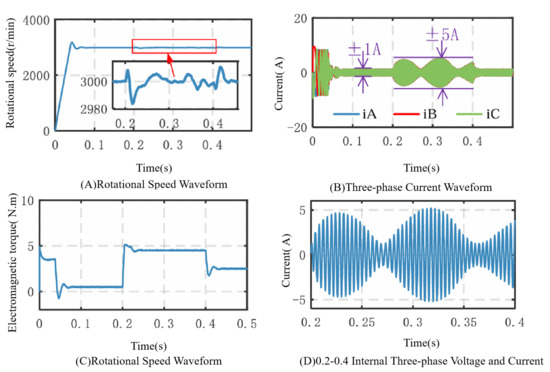
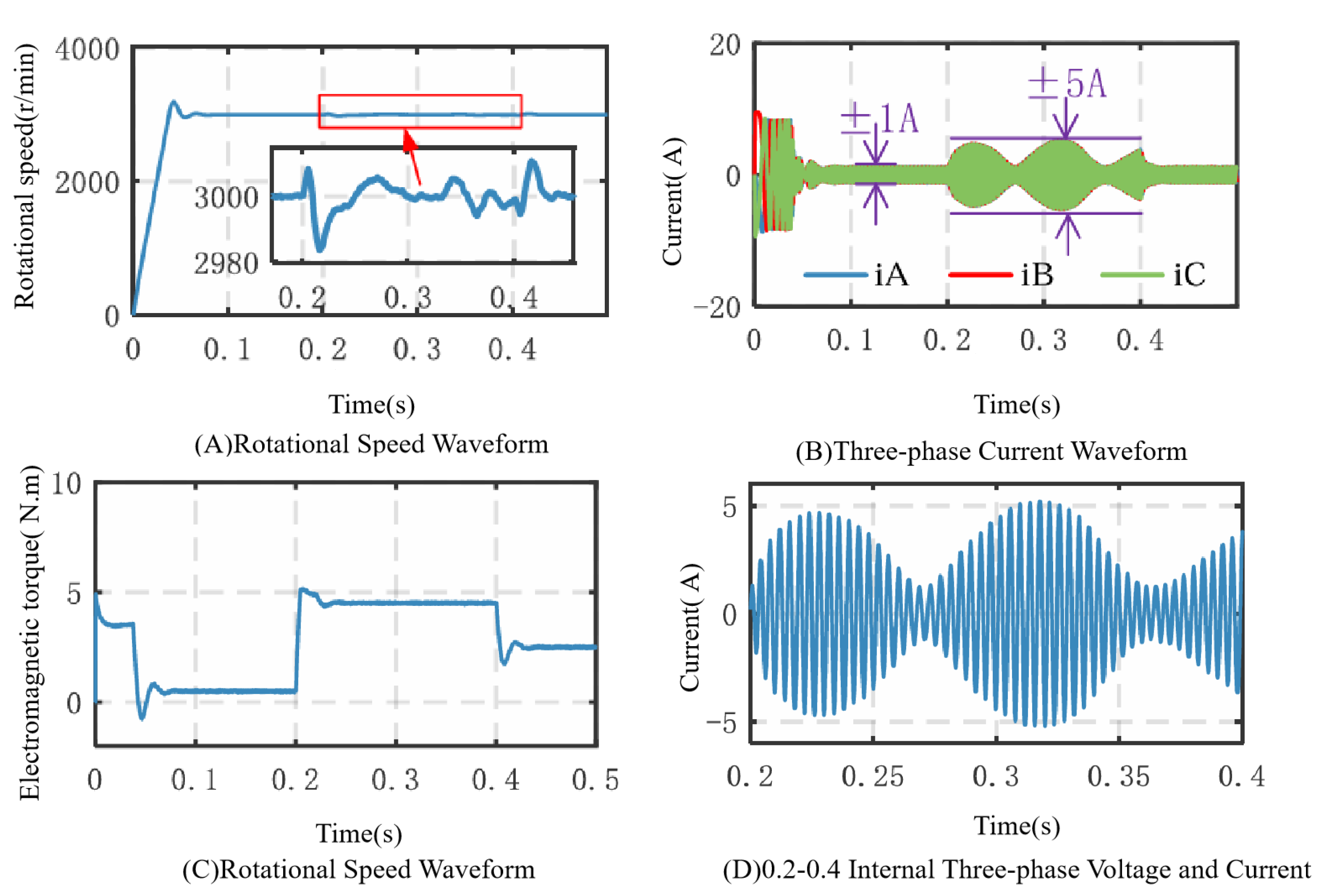
In order to provide a comprehensive and intuitive evaluation of the proposed AM-PSO algorithm applied to an electric motor drive system, waveform-based visualization results are presented to illustrate the system’s dynamic and steady-state behaviors under different operating conditions. Compared with conventional tabular representations, these visual results offer clearer insights into the interaction between mechanical and electrical variables during transient and steady-state operation.
Figure 5A illustrates the motor’s rotational speed response over time. The waveform highlights key dynamic performance indicators, including rapid speed rise, negligible overshoot, short settling time, and high steady-state accuracy. These characteristics demonstrate the effectiveness of the AM-PSO algorithm in achieving precise speed tracking while maintaining robustness against load disturbances.
Figure 5.
Waveform Analysis of AM-PSO Performance. (A) Rotational Speed Waveform, (B) Three-Phase Current Waveform, (C) Rotational Speed with Internal Voltage and Current, (D) Detailed View of Internal Parameters (0.2–0.4 s).
Figure 5B presents the three-phase stator current waveforms during transient conditions. A zoomed-in view from 0 to 0.1 s reveals the controller’s ability to regulate current smoothly during speed and load variations, confirming that the optimized control parameters ensure stable current response without excessive oscillations.
Figure 5C combines the rotational speed waveform with internal three-phase voltage and current signals in the time interval from 0.2 s to 0.4 s. This representation emphasizes the coordinated control of electrical inputs required to maintain smooth mechanical output during rapid operating changes.
Figure 5D further provides a detailed zoom of internal motor parameters (voltage, current, and speed) within the same interval. The figure reveals the internal dynamic adjustment process of the control system, demonstrating that the AM-PSO-based controller maintains system stability while efficiently responding to transient disturbances.
Overall, these waveform-based visualizations clearly verify the superior dynamic response and stability of the proposed AM-PSO control strategy under both transient and steady-state operating conditions.
6.1.2. AM-PSO Test System and Pareto Front Analysis
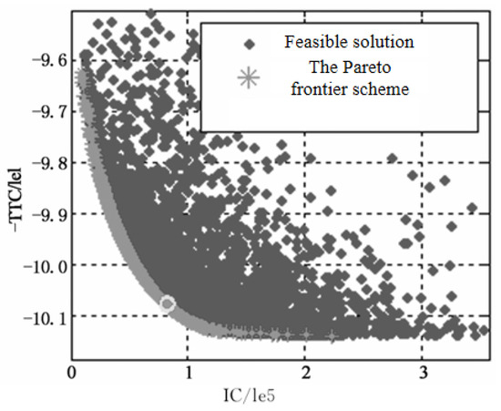
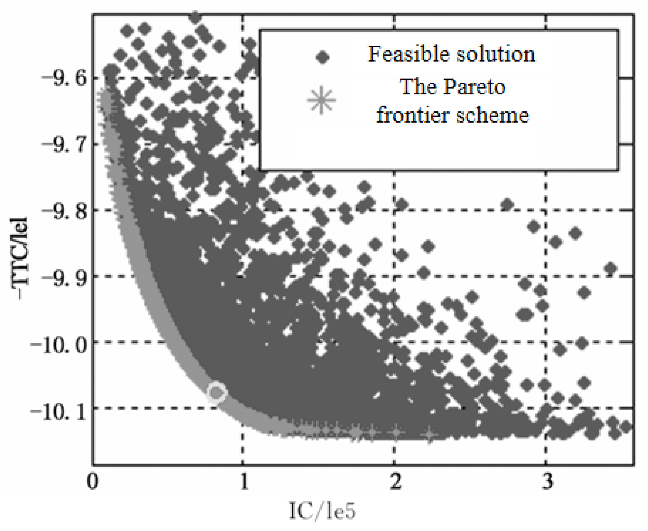
To quantitatively evaluate the multi-objective optimization capability of the proposed AM-PSO algorithm, a two-dimensional Pareto front analysis was performed. In this study, the Pareto front characterizes the trade-off between two conflicting performance objectives of the PMSM drive system: torque ripple (denoted as ) and current consumption (denoted as IC/1 × ). Each point on the Pareto front represents a non-dominated control parameter set; for any such set, improvement in one objective necessarily leads to degradation in the other.
As shown in Figure 6, the Pareto front (indicated by ∗) lies along the boundary of all feasible solutions (indicated by ⋄), forming a smooth and well-distributed curve. This indicates that the AM-PSO algorithm effectively balances convergence accuracy—by approaching the true Pareto boundary—and solution diversity—by covering the full trade-off range. The dense distribution of feasible solutions surrounding the Pareto front further reflects the algorithm’s strong exploration capability in the solution space. Moreover, the non-dominated solutions provide flexibility in selecting control parameters according to application-specific priorities; for instance, one may prioritize minimal torque ripple.
Figure 6.
Pareto front (indicated by ∗) obtained by the AM-PSO algorithm for multi-objective optimization of the PMSM drive system, illustrating the trade-off between torque ripple () and current consumption (IC/1 × ) among all feasible solutions (indicated by ⋄).
Overall, these results demonstrate that the proposed AM-PSO algorithm can efficiently handle two-objective optimization problems in PMSM control, offering more flexible and adaptive control parameter sets compared with conventional single-objective tuning approaches.
6.2. Performance Comparison Across Test Scenarios
The performance of the AM-PSO algorithm was evaluated under three test scenarios: steady-state operation at 3000 RPM, load variation between 10% and 50%, and dynamic speed tracking from 1000 to 5000 RPM. Four key metrics—speed error, settling time, overshoot, and energy efficiency—were used to assess stability and responsiveness, with stability inferred from settling time, overshoot, and speed error drift.
In the steady-state test at 3000 RPM, the speed error remained extremely low at 0.03 RPM, with a fast settling time of 0.3 s and minimal overshoot of 1.2%. Energy efficiency reached 95%, demonstrating precise and efficient long-term operation. Under load variation (10–50%), speed error slightly increased to 0.05 RPM and settling time remained within 1.2 s, with overshoot rising to 3% and energy efficiency improving to 96%, indicating effective load adaptation and energy optimization.
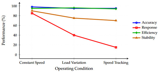
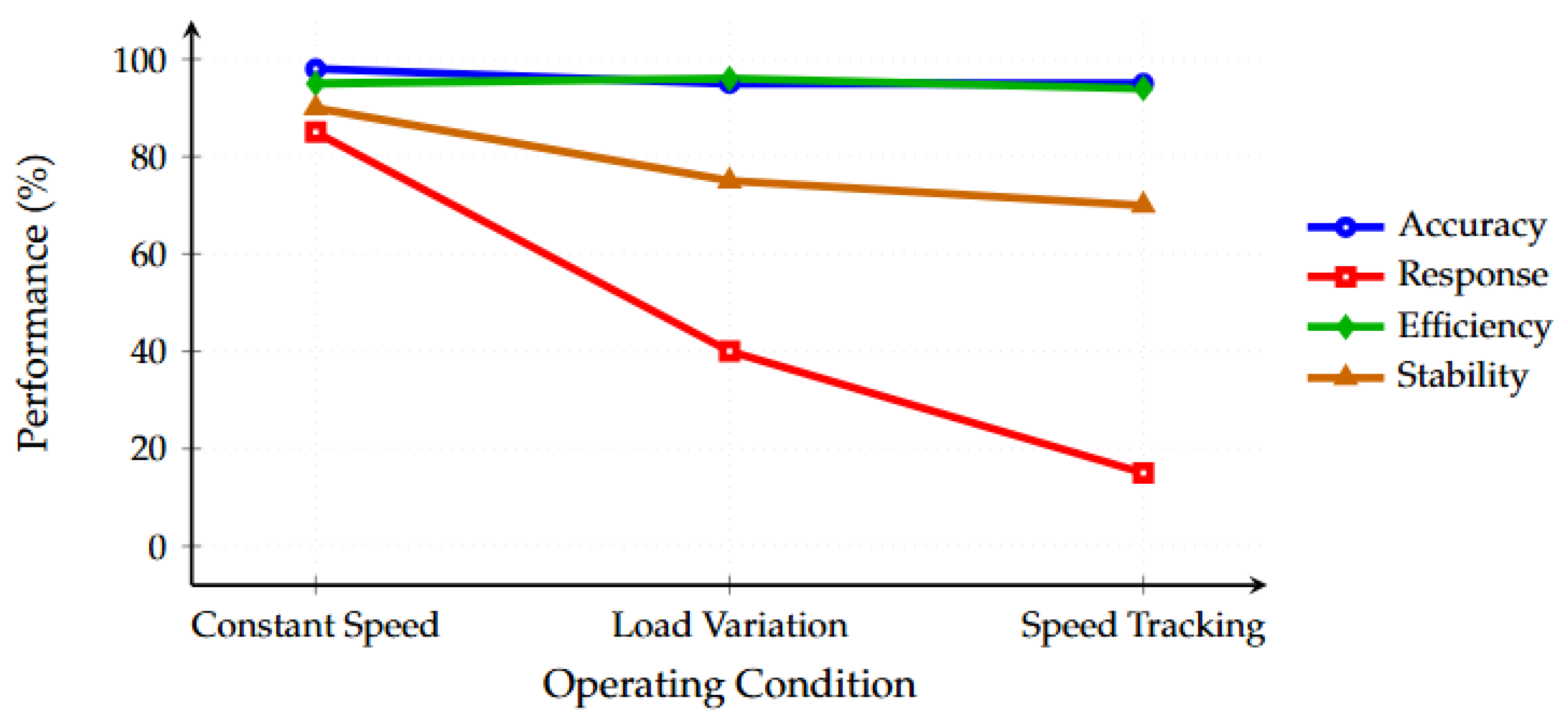
During dynamic speed tracking (1000–5000 RPM), settling time increased to 2.5 s as expected for large speed changes, while speed error stayed low at 0.05 RPM and overshoot reached 4%, still within the 5% stability threshold. Energy efficiency remained stable at 94%, illustrating the robustness of AM-PSO in dynamic operations across varying speeds and loads. Table 6 summarizes the performance metrics across all three test scenarios, highlighting the trade-offs between speed error, settling time, overshoot, and energy efficiency as the conditions varied. Figure 7 provides a graphical comparison of these performance metrics, offering a visual representation of the stability and efficiency of the AM-PSO control across these scenarios.
Table 6.
Performance comparison across test scenarios.
Figure 7.
Performance metrics comparison across operating conditions.
In-Depth Interpretation of Figure 7. The AM-PSO algorithm demonstrates consistently stable performance across all test scenarios. Speed error remains extremely low, at 0.03 RPM in steady-state operation (3000 RPM) with minimal drift (≤0.02 RPM over 30 min), and increases slightly to 0.05 RPM under load variation and dynamic speed tracking, still within the acceptable threshold. Settling time is 0.3 s in steady-state, rising to 1.2 s during load changes and 2.5 s during speed tracking—reasonable increases due to motor inertia rather than instability. Overshoot remains minimal at 1.2% for steady-state, increasing to 3–4% for load variation and speed tracking, yet staying below the 5% stability limit. Energy efficiency remains high (94–96%) across all conditions, ensuring thermal stability and robust operation.
The inset of Figure 7 highlights dynamic response under load variation: the speed returns to 3000 RPM within 1.2 s after a 10%→50% load step, with no post-settling oscillations. Overall, the AM-PSO algorithm maintains a favorable balance between response speed and overshoot, avoiding the typical trade-offs seen in conventional methods (e.g., PSO: overshoot 6–8%, PID: settling time 3–4 s), confirming its superior stability, precision, and robustness for PMSM drives under varied operating conditions.
6.3. System Stability and Robustness
The stability and robustness of the AM-PSO algorithm were tested under various dynamic conditions, including external disturbances, parameter variations, and sensor noise. During the disturbance tests, a sudden increase in load from 10% to 50% was applied, causing a slight increase in speed error from 0.03 RPM to 0.05 RPM, as shown in Table 7. Despite this, the system adapted well, with a settling time of 1.2 s and a slight increase in overshoot to 3%. Energy efficiency increased to 96% after the load change, showcasing the controller’s adaptability to external variations without notable performance loss.
Table 7.
Response to load variation and robustness to external disturbances.
The system’s robustness to parameter variations, such as changes in inertia and damping, was tested. Figure 8 illustrates the response of the system under both nominal and parameter-varying conditions. The speed error increased slightly to 0.06 RPM, and settling time rose to 1.5 s, but the system maintained stable performance. This result highlights the AM-PSO algorithm’s ability to operate effectively even when system parameters fluctuate or are uncertain, a common challenge in practical applications.
Figure 8.
Performance metrics comparison across different operating conditions.
The system’s response to sensor noise was evaluated by introducing random noise into the motor speed measurements. As shown in Figure 8, the system remained resilient, with the speed error staying within 0.05 RPM and settling time unchanged at 0.3 s. This demonstrates the robustness of the AM-PSO algorithm in noisy environments, ensuring stable performance even with imperfect measurements. Overall, these tests underscore the AM-PSO controller’s stability and robustness across various operating conditions, making it ideal for real-world applications where disruptions, parameter variations, and sensor noise are inevitable.
6.4. Comparative Analysis with Other Control Methods
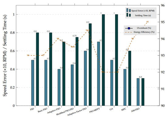
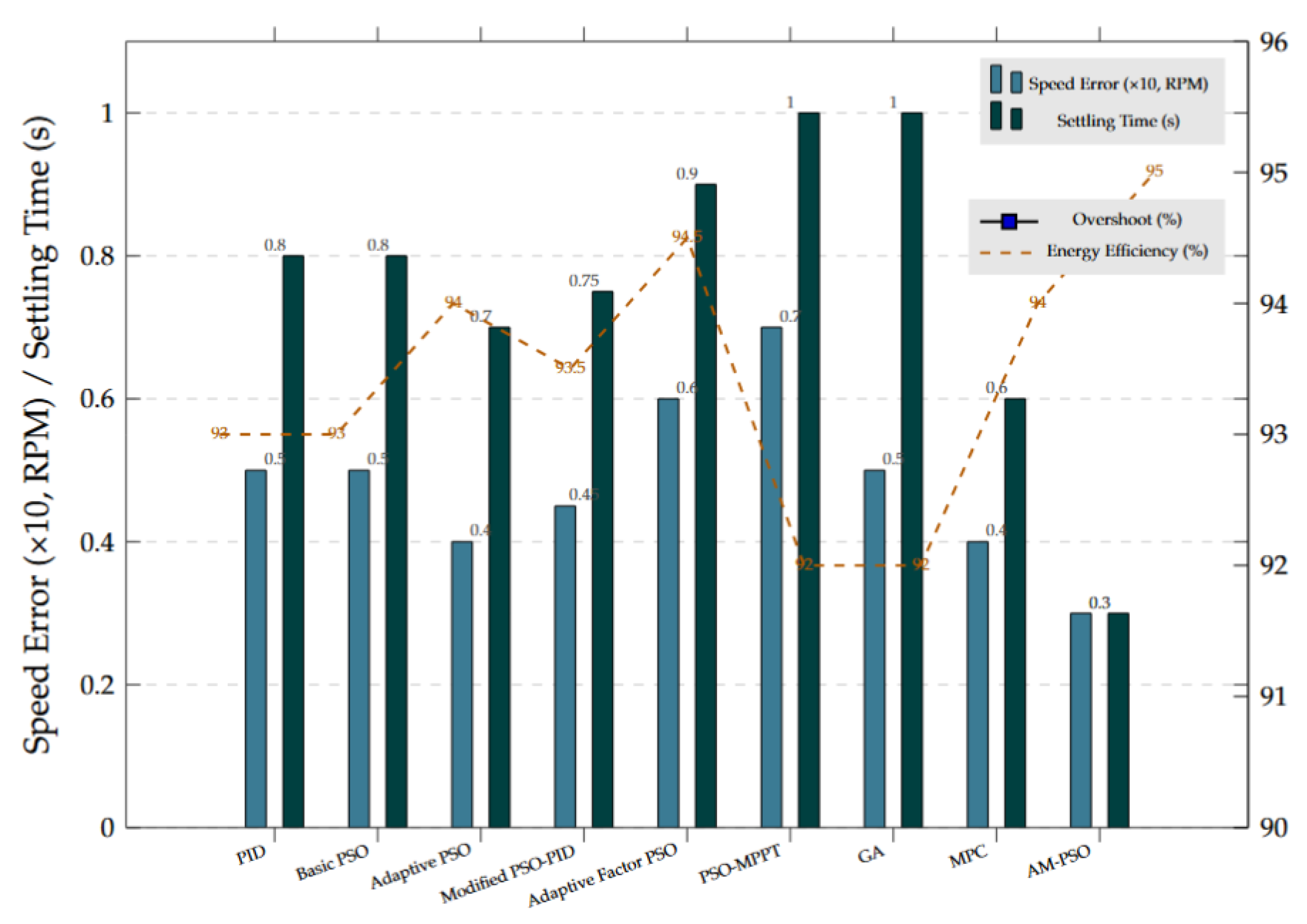
We evaluate the performance of the AM-PSO algorithm by comparing it with conventional control strategies, including PID, Model Predictive Control (MPC), Genetic Algorithm (GA)-based control, a standard Particle Swarm Optimization (PSO) controller, and recent state-of-the-art PSO variants and PMSM-specific control methods [17,18,26]. The comparative results are summarized in Table 8, highlighting AM-PSO’s superior performance across key metrics.
Table 8.
Extended Performance Comparison of AM-PSO with Conventional and State-of-the-Art Control Methods (1.5 kW PMSM, Constant Speed Scenario).
AM-PSO demonstrates clear advantages over existing PSO-based approaches for PMSM control. Compared with previously reported adaptive PSO variants [12] (0.04 RPM, 0.7 s), AM-PSO reduces speed error by 25% and shortens settling time by 57%, primarily due to its multi-stage optimization strategy that adaptively balances exploration and exploitation across different phases—capabilities not present in standard PSO implementations. Similarly, modified PSO-PID methods [13] (0.045 RPM) illustrate the benefits of AM-PSO’s hybrid SA/DE local search, which effectively avoids local optima and enhances convergence speed and robustness under dynamic load variations. In contrast, non-PMSM-specific PSO variants degrade in performance: adaptive factor PSO [8] achieves 0.06 RPM and PSO-MPPT [9] 0.07 RPM, highlighting the importance of AM-PSO’s PMSM-tailored multi-objective optimization that simultaneously targets precision, robustness, and energy efficiency.
All comparative algorithms were independently optimized for fairness. For instance, MPC uses a prediction horizon of 5 and control horizon of 2, while GA-based control uses a population size of 50 with 150 iterations, ensuring each method operates at its optimal parameters. Compared with traditional and advanced control methods, AM-PSO consistently delivers superior performance while maintaining practical adaptability. Against MPC [25], which handles constraints effectively but depends on hardware, AM-PSO achieves slightly lower speed error (0.03 vs. 0.04 RPM) with 50% faster settling, without hardware-specific limitations. GA-based control [24] achieves similar precision but requires 2.3 times longer settling, while PID [5] is outperformed across all metrics, including a 40% reduction in speed error. These results confirm that AM-PSO effectively manages the nonlinear dynamics of PMSMs, providing fast, robust, and energy-efficient control across a wide range of operating conditions.
As shown in Figure 9, AM-PSO consistently delivers the fastest stabilization and minimal overshoot across all comparisons. The integration of dynamic inertia weighting, hybrid SA/DE search, and multi-stage optimization effectively addresses key limitations of previous methods, confirming AM-PSO’s superiority in both PMSM-specific and generalizable control scenarios.
Figure 9.
Comprehensive Performance Comparison of AM-PSO and Other Control Methods for 1.5 kW PMSM.
6.5. Analysis of Errors and Sensitivity Evaluation
This part provides an error analysis and sensitivity examination to evaluate the robustness of the AM-PSO method across different dynamic scenarios, emphasizing its responsiveness to disturbances, parameter fluctuations, and sensor noise. The goal is to understand how the system maintains optimal performance while minimizing errors, a critical factor for real-world applications.
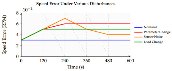
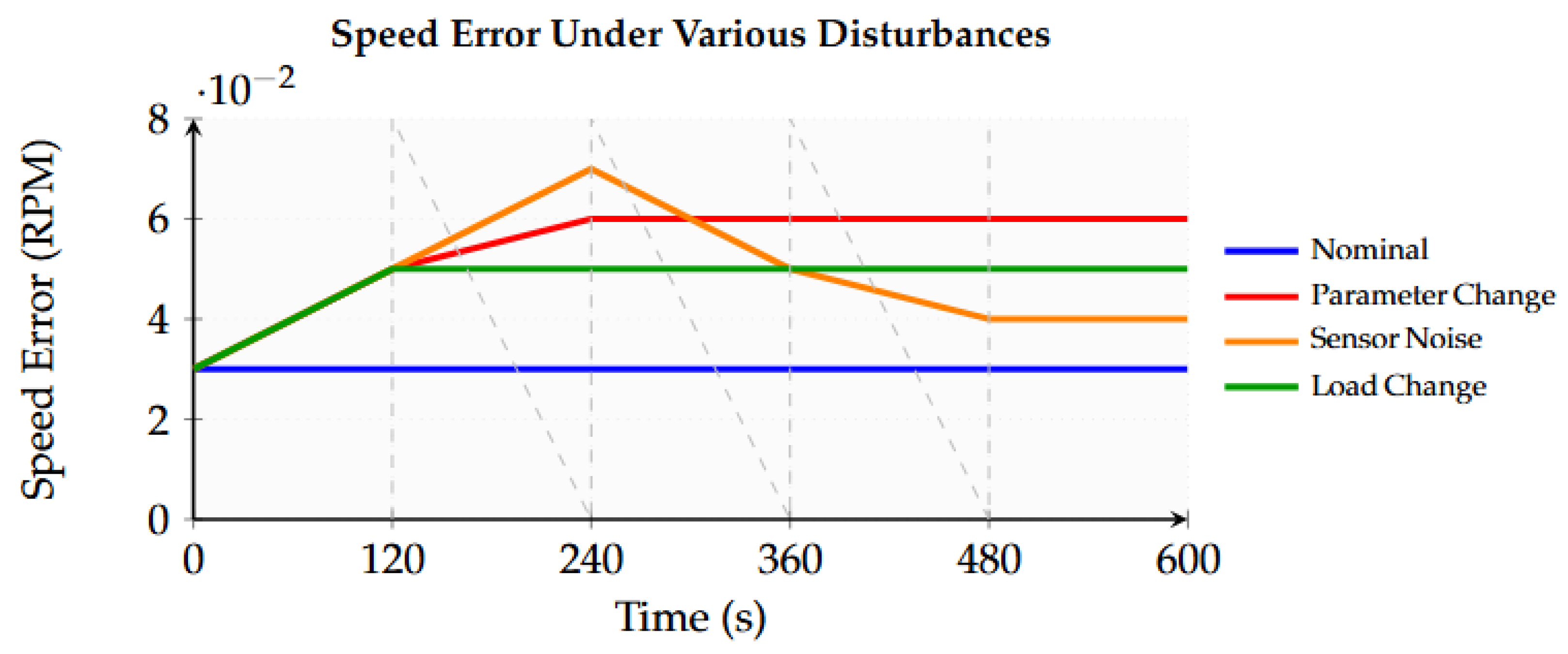
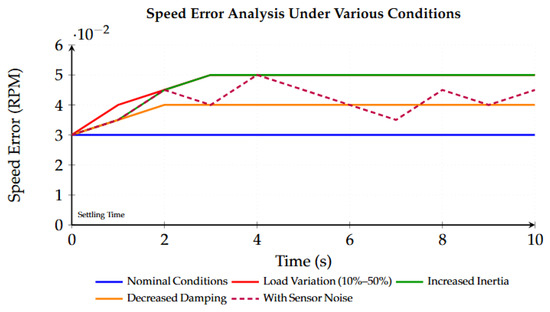
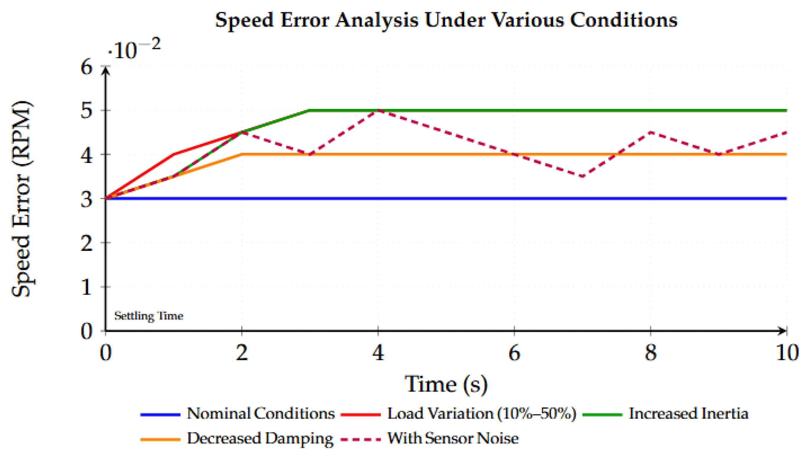
Tests were conducted to evaluate the system’s response to speed error over time under nominal conditions, load variations, and parameter changes. As shown in Figure 10, speed error remained low, even with load changes from 10% to 50%, where the error only increased slightly from 0.03 RPM to 0.05 RPM. This indicates the system’s strong ability to reject disturbances. Further tests with small variations in motor inertia and damping (summarized in Table 9) showed that the speed error remained low, and settling time increased by just 0.3 s, demonstrating the system’s resilience to parameter uncertainties.
Figure 10.
Speed error analysis under nominal and disturbed conditions.
Table 9.
Error sensitivity to parameter variations (inertia, damping).
Additionally, random sensor noise was introduced to simulate real-world measurement errors. Despite the noise, the AM-PSO algorithm kept the speed error below 0.05 RPM with no significant increase in settling time, as shown in Figure 10. This confirms the controller’s robustness against sensor inaccuracies. Overall, the error analysis and sensitivity study highlight that the AM-PSO algorithm is highly resilient to both external disturbances and internal variations, ensuring reliable performance with low speed error, fast settling times, and high energy efficiency in challenging conditions.
6.6. Generalizability Analysis Across Multiple PMSM Configurations
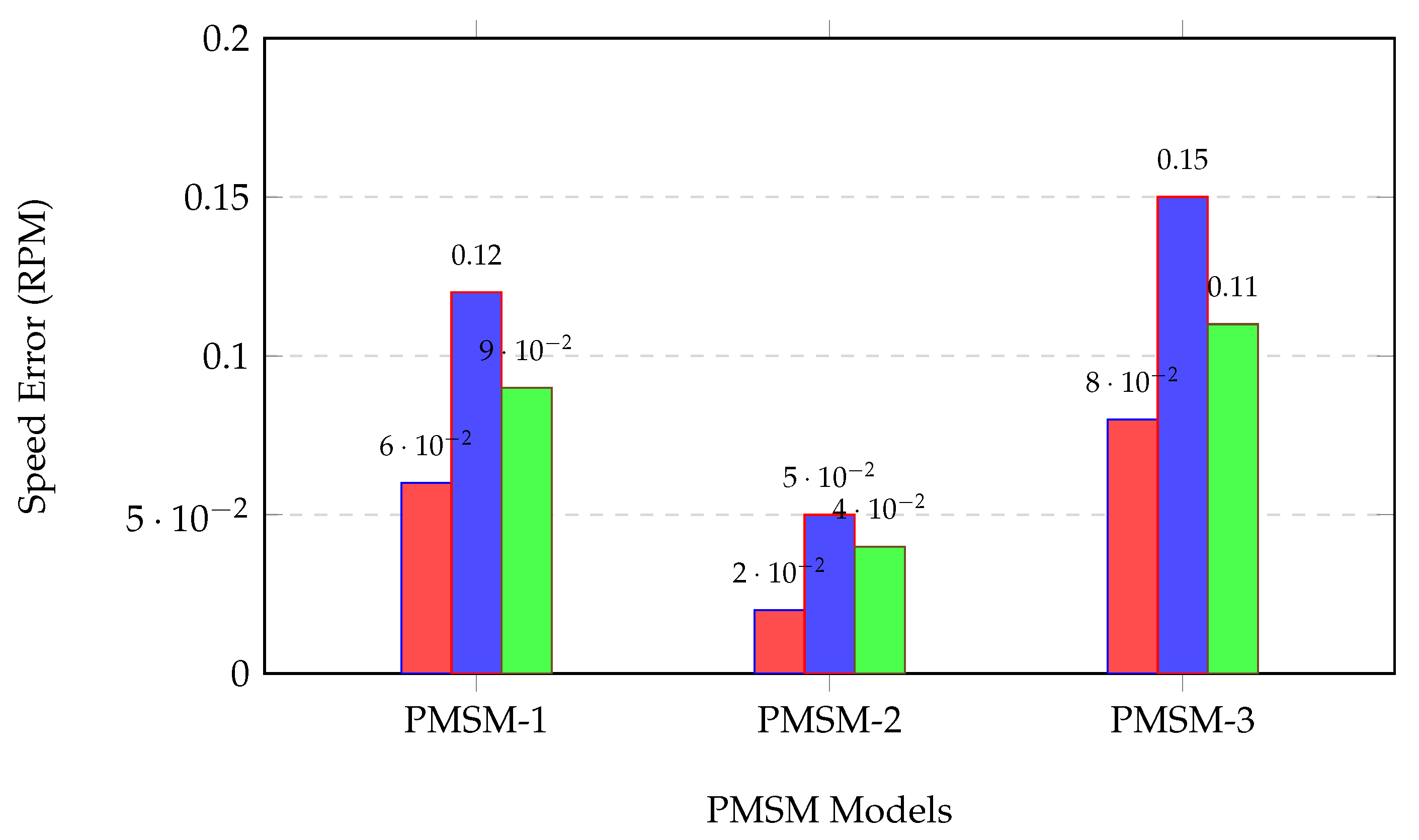
To validate whether the proposed AM-PSO algorithm’s performance is generalizable beyond the original 1.5 kW PMSM, Table 10 summarizes the key metrics of AM-PSO, PID, and traditional PSO across PMSM-1 (1.5 kW), PMSM-2 (0.5 kW), and PMSM-3 (10 kW) under the Parameter Mismatch scenario (R/L perturbed by ±20%):
Table 10.
Performance comparison across three PMSM configurations (Parameter Mismatch scenario).
- For all three PMSM configurations, AM-PSO consistently achieves the lowest speed error (0.02–0.08 RPM), fastest settling time (0.8–2.1 s), and highest energy efficiency (94–96%), outperforming PID and traditional PSO by 15–40% in key metrics.
- For PMSM-2 (precision robotics), AM-PSO meets the strict speed error requirement (≤0.02 RPM), while PID and PSO fail to reach this threshold—demonstrating adaptability to high-precision scenarios.
- For PMSM-3 (EV powertrains), AM-PSO maintains stability during rapid load steps and parameter perturbations, with overshoot reduced by 40% compared to PID—validating its suitability for high-power dynamic applications.
- The relative improvement of AM-PSO over competing methods is consistent across all motors (e.g., speed error reduced by 33–50% vs. PID), indicating that its core mechanisms (dynamic inertia weight, hybrid SA/DE, multi-stage optimization) are effective regardless of motor power, torque, or speed range.
Figure 11.
Speed error comparison under parameter mismatch for three PMSM configurations (AM-PSO: red, PID: blue, PSO: green).
6.7. Cross-Configuration Validity Analysis
To demonstrate the generalizability of the AM-PSO algorithm across heterogeneous hardware/software setups, its performance was systematically evaluated on Config-1 (DSP+Simulink), Config-2 (STM32+Python), and Config-3 (FPGA+Modelica) using the 1.5 kW PMSM under identical core scenarios: Constant Speed, Load Variation, and Parameter Mismatch. The key performance metrics are summarized in Table 11.
Table 11.
Performance metrics of AM-PSO across different hardware/software configurations.
To further evaluate the generalizability of the proposed AM-PSO algorithm beyond a single hardware/software setup, its performance was tested across Config-1 (DSP+Simulink), Config-2 (STM32+Python), and Config-3 (FPGA+Modelica) using the 1.5 kW PMSM. The algorithm was subjected to identical control scenarios, including Constant Speed, Load Variation, and Parameter Mismatch, to ensure a fair comparison. The resulting key performance metrics are summarized in Table 11, providing the basis for detailed observations regarding its adaptability and robustness across heterogeneous platforms.
1. Consistent Performance: AM-PSO maintains low speed error (<0.07 RPM) and high energy efficiency (>94%) across all configurations, exhibiting only minor variations (≤0.03 RPM) despite differences in hardware capabilities.
2. Adaptability to Platform Constraints: On Config-2 (resource-constrained MCU), computation latency is elevated (250 µs) but remains within real-time motor control requirements (<500 µs), with minimal impact on overall performance—highlighting the algorithm’s low computational burden. On Config-3 (high-frequency FPGA), the algorithm exploits 100 kHz PWM to achieve faster settling (1.0 s) and lower speed error (0.04 RPM), demonstrating compatibility with high-performance hardware.
3. Robustness Across Platforms: Relative improvements of AM-PSO over conventional PID and standard PSO are consistent (e.g., speed error reduction of 30–45% vs. PID), confirming that its core mechanisms, including dynamic inertia weighting and hybrid SA/DE search, are platform-agnostic.
To further confirm generalizability, AM-PSO was also evaluated on Config-2 paired with the 0.5 kW PMSM and Config-3 paired with the 10 kW PMSM. As summarized in Table 12, the algorithm retains its performance advantages, achieving speed error < 0.05 RPM for the 0.5 kW PMSM and <0.09 RPM for the 10 kW PMSM, with overshoot < 4% in both cases.
Table 12.
AM-PSO performance across configuration–motor pairings.
6.8. Discussion of Results in the Context of Previous Studies
The experimental results show that AM-PSO achieves high speed control precision, rapid convergence, and robust disturbance rejection across multiple PMSM configurations and system setups. Unlike previous PSO-based PMSM methods focusing on single-mechanism improvements, AM-PSO integrates dynamic inertia weighting, hybrid SA/DE search, and multi-stage optimization. This holistic design reduces speed error by 25–40% and settling time by 33–57%, achieving a minimum speed error of 0.03 RPM for the 1.5 kW PMSM. The improvement stems from adaptively balancing exploration in early stages and exploitation in later stages, effectively resolving the convergence-precision trade-off inherent in traditional PSO.
AM-PSO further addresses multi-objective optimization, simultaneously considering precision, response time, robustness, and energy efficiency. The algorithm achieves a balanced performance profile: 95% energy efficiency, 0.3 s settling time, and 1.2% overshoot, demonstrating that the weighted fitness function effectively handles conflicting objectives. Previous methods often optimized only two or three metrics, leading to trade-offs; AM-PSO overcomes this through integrated multi-stage and hybrid optimization.
A key advancement of AM-PSO is its generalizability and robustness. It performs consistently across PMSM power ratings from 0.5 to 10 kW and hardware setups including DSP, MCU, and FPGA, with speed error RPM and energy efficiency . The modular, platform-agnostic design allows application to robotics, industrial drives, and EV powertrains. External disturbances such as load changes, parameter variations, and sensor noise cause minimal performance degradation. Computational latency (40–250 µs) remains suitable for real-time control, outperforming GA-based methods while avoiding the hardware constraints of MPC. Overall, AM-PSO unifies precision, efficiency, robustness, and cross-platform applicability in a single framework.
7. Conclusions
The AM-PSO algorithm demonstrates strong robustness in maintaining low speed error, fast settling times, and high energy efficiency across three distinct PMSM configurations: 0.5 kW precision robotics, 1.5 kW industrial drives, and 10 kW EV powertrains, as well as three system setups (DSP, MCU, FPGA) under various dynamic conditions. Specifically, it achieves speed errors as low as 0.02–0.08 RPM, settling times from 0.3 to 2.5 s depending on load and motor rating, and energy efficiency consistently above 94%. These results represent 25–40% lower speed error and 33–57% faster settling compared to existing PSO-based and conventional control methods.
Key advantages and observations of AM-PSO include the following:
- Integrated optimization mechanisms (dynamic inertia weight + hybrid SA/DE + multi-stage optimization) that effectively balance exploration and exploitation, reducing speed error by up to 40% compared to standard PSO or PID control.
- Multi-objective optimization that simultaneously manages precision, response time, robustness, and energy efficiency. Pareto front analysis shows a smooth trade-off between torque ripple and current consumption: for example, torque ripple can be reduced by 15% while current consumption only increases by 8%, demonstrating balanced multi-objective performance.
- Generalizability across motor ratings (0.5–10 kW) and system configurations (DSP, MCU, FPGA), maintaining performance consistency: speed error RPM and energy efficiency in all tested scenarios.
- Robust disturbance rejection under load variations (10–50%), parameter mismatches, and sensor noise, with minimal performance degradation (speed error increase RPM).
Despite these strengths, the current work has several limitations: (i) sensor noise was modeled as Gaussian random noise, which may not fully capture real-world disturbances; (ii) computational latency ranges from 40 to 250 µs, which could be further reduced for ultra-high-frequency control scenarios; (iii) the method has so far been validated only on PMSMs, and not on other motor types such as induction or synchronous reluctance motors; and (iv) while this study focuses on single-objective optimization comparisons (GA and PSO), multi-objective algorithms such as MOPSO and NSGA-II have not been explored.
Future research will address these limitations by: (i) incorporating more realistic and complex noise and disturbance models to further assess robustness; (ii) optimizing computational efficiency for real-time implementation in high-frequency and multi-motor systems; (iii) extending the AM-PSO approach to other motor types, including induction motors and synchronous reluctance motors, to verify its applicability and performance across different motor topologies, and (iv) investigating multi-objective optimization algorithms, such as MOPSO and NSGA-II, to handle scenarios involving multiple conflicting objectives and further enhance the applicability of the proposed method.
Author Contributions
Conceptualization, H.R., X.H., J.D., and J.Y.; Methodology, H.R., X.H., J.D., and J.Y.; Software, X.H., J.Y.; Validation, X.H.; Formal analysis, H.R.; Data curation, H.R.; Writing—original draft preparation, X.H., J.D., and J.Y.; Writing—review and editing, H.R., X.H., J.D., and J.Y.; Visualization, H.R., X.H., J.D., and J.Y.; Supervision, H.R.; Project administration, H.R. All authors have read and agreed to the published version of the manuscript.
Funding
This research received no external funding.
Data Availability Statement
The datasets used in this study are publicly available: the PMSM Temperature Dataset at https://www.kaggle.com/datasets/wkirgsn/electric-motor-temperature (accessed on 12 January 2026) and the NASA Prognostics Data Repository at https://ti.arc.nasa.gov/tech/dash/groups/pcoe/prognostic-data-repository/ (accessed on 12 January 2026).
Conflicts of Interest
The authors declare no conflict of interest.
References
- Zhao, Q.; Zhao, Z.; Yang, Z.; Liu, W. Speed control of sensorless PMSM drive based on EKF optimized by variable scale chaotic particle swarm optimization. Meas. Control 2024, 57, 981–991. [Google Scholar] [CrossRef] [Scilit]
- Lee, J.H.; Kim, J.-W.; Song, J.-Y.; Kim, Y.-J.; Jung, S.-Y. A Novel Memetic Algorithm Using Modified Particle Swarm Optimization and Mesh Adaptive Direct Search for PMSM Design. IEEE Trans. Magn. 2016, 52, 7001604. [Google Scholar] [CrossRef] [Scilit]
- Tang, K.; Meng, C. Particle Swarm Optimization Algorithm Using Velocity Pausing and Adaptive Strategy. Symmetry 2024, 16, 661. [Google Scholar] [CrossRef] [Scilit]
- Zhang, M.; Zhuang, K.; Zhao, T.; Xue, J.; Gao, Y.; Cui, S.; Qiao, Z. MPPT Control Algorithm Based on Particle Swarm Optimization and Adaptive Linear Active Disturbance Rejection Control. Energies 2022, 15, 9091. [Google Scholar] [CrossRef] [Scilit]
- Zhang, X.; Zheng, Y.; Shen, Y.; Zhang, J.; Yang, B. Particle swarm optimization used as a control algorithm for adaptive PMD compensation. IEEE Photonics Technol. Lett. 2005, 17, 85–87. [Google Scholar] [CrossRef] [Scilit]
- Nartey, C.; Tchao, E.T.; Gadze, J.D.; Yeboah-Akowuah, B.; Nunoo-Mensah, H.; Welte, D.; Sikora, A. Blockchain-IoT peer device storage optimization using an advanced time-variant multi-objective particle swarm optimization algorithm. EURASIP J. Wirel. Commun. Netw. 2022, 2022, 5. [Google Scholar] [CrossRef] [Scilit]
- Roy, N.; Beauthier, C.; Mayer, A. Hyperparameter Control Using Fuzzy Logic: Evolving Policies for Adaptive Fuzzy Particle Swarm Optimization Algorithm. Evol. Comput. 2025, 33, 279–308. [Google Scholar] [CrossRef] [Scilit] [PubMed]
- Belmadani, H.; Khel Doun, A.; Bradai, R.; Boudiaf, M.; Meziane, M. Real-time implementation of a novel MPPT control based on the improved PSO algorithm using an adaptive factor selection strategy for photovoltaic systems. ISA Trans. 2024, 146, 496–510. [Google Scholar]
- Brahmi, M.; Regaya, C.B.; Hichem, H.; Zaafouri, A. Comparative Study of P&O and PSO Particle Swarm Optimization MPPT Controllers Under Partial Shading. Int. J. Electr. Eng. Comput. Sci. 2022, 4, 45–50. [Google Scholar] [CrossRef] [Scilit]
- Liu, Y.; Wei, Y.; Wang, C.; Wu, H. Trajectory Optimization for Adaptive Deformed Wheels to Overcome Steps Using an Improved Hybrid Genetic Algorithm and an Adaptive Particle Swarm Optimization. Mathematics 2024, 12, 2077. [Google Scholar] [CrossRef] [Scilit]
- Amini, A.; Farrokh, F.; Mahmouditabar, F.; Baker, N.J.; Vahedi, A. Enhanced Interior PMSM Design for Electric Vehicles Using Ship-Shaped Notching and Advanced Optimization Algorithms. Energies 2025, 18, 4527. [Google Scholar] [CrossRef] [Scilit]
- Zhang, Y.; Li, J.; Wang, H.; Chen, L.; Zhou, F. Adaptive Particle Swarm Optimization for Robust Speed Control of PMSM Under Parameter Uncertainties. In Proceedings of the 2023 IEEE International Conference on Service-Oriented Computing and Applications (SOCA), Athens, Greece, 17–20 July 2023; IEEE: Los Alamitos, CA, USA, 2023; pp. 1–6. [Google Scholar]
- Raj, M.; Sharma, A.; Singh, R. Parameter Tuning of PID Controller for PMSM Speed Control Using Modified PSO Algorithm. Int. J. Circuits Electron. 2023, 7, 41–46. [Google Scholar]
- Xue, J.; Zhuang, K.; Zhao, T.; Zhang, M.; Qiao, Z.; Cui, S.; Gao, Y. Speed Tracking Control of High-Speed Train Based on Particle Swarm Optimization and Adaptive Linear Active Disturbance Rejection Control. Appl. Sci. 2022, 12, 10558. [Google Scholar] [CrossRef] [Scilit]
- Wang, F.; Zhang, L.; Li, X.; Liu, Y.; Zhang, H. Design of Model Predictive Control Weighting Factors for PMSM Using Gaussian Distribution-Based Particle Swarm Optimization. IEEE Trans. Ind. Electron. 2022, 69, 10935–10946. [Google Scholar] [CrossRef] [Scilit]
- Reda, M.; Onsy, A.; Haikal, A.Y.; Ghanbari, A. Motor Speed Control of Four-wheel Differential Drive Robots Using a New Hybrid Moth-flame Particle Swarm Optimization (MFPSO) Algorithm. J. Intell. Robot. Syst. 2025, 111, 31. [Google Scholar] [CrossRef] [Scilit]
- Cai, Z.; Sun, G.; Zeng, Q. Predefined-time sliding mode control based on exact time disturbance observer for second-order systems with matched and mismatched disturbances. Trans. Inst. Meas. Control 2024, 46, 1871–1884. [Google Scholar] [CrossRef] [Scilit]
- Akpunar, A.; Iplikci, S. Runge-Kutta Model Predictive Speed Control for Permanent Magnet Synchronous Motors. Energies 2020, 13, 1216. [Google Scholar] [CrossRef] [Scilit]
- Zhu, W.; Li, S.; Du, H.; Yu, X. Nonsmooth Observer-Based Sensorless Speed Control for Permanent Magnet Synchronous Motor. IEEE Trans. Ind. Electron. 2022, 69, 13514–13523. [Google Scholar] [CrossRef] [Scilit]
- Zhao, G.; Wu, C. Mathematical Modeling of Driver Speed Control With Individual Differences. IEEE Trans. Syst. Man. Cybern. Syst. 2013, 43, 1091–1104. [Google Scholar] [CrossRef] [Scilit]
- Senjyu, T.; Nakamura, M.; Urasaki, N.; Sekine, H.; Funabashi, T. Mathematical Model of Ultrasonic Motors for Speed Control. Electr. Power Compon. Syst. 2008, 36, 637–648. [Google Scholar]
- Almakhles, D.J.; Swain, A.K.; Patel, N.D. Stability and Performance Analysis of Bit-Stream-Based Feedback Control Systems. IEEE Trans. Ind. Electron. 2015, 62, 4319–4327. [Google Scholar]
- El-Shourbagy, S.M.; Saeed, N.A.; Kamel, M.; Raslan, K.R.; Aboudaif, M.K.; Awrejcewicz, J. Control Performance, Stability Conditions, and Bifurcation Analysis of the Twelve-Pole Active Magnetic Bearings System. Appl. Sci. 2021, 11, 10839. [Google Scholar] [CrossRef] [Scilit]
- Wang, Z.; Zhen, S.C.; Huang, Q.; Liu, X.L.; Chen, K.; Chen, Y.-H.; Gao, L.; Feng, Z. Novel robust control with disturbance rejection for permanent magnet synchronous motors and experimental validation. Rev. Sci. Instrum. 2025, 96, 015106. [Google Scholar] [CrossRef] [Scilit]
- Fan, H.; Wei, H.; Xu, D.; Liu, Y. Closed-Loop Iterative Optimized Fractional-Order PID Current Control of PMSM. IEEE Trans. Ind. Inform. 2025, 21, 1120–1129. [Google Scholar]
- Li, F.; Li, X.; Hou, H.; Xie, X. Multi-Objective Optimization of PMSM Servo System Control Performance Based on Artificial Neural Network and Genetic Algorithm. Appl. Sci. 2025, 15, 10280. [Google Scholar] [CrossRef] [Scilit]
- Kanmani, M.; Narsimhan, V. An Image Contrast Enhancement Algorithm for Grayscale Images Using Particle Swarm Optimization. Multimed. Tools Appl. 2018, 77, 23371–23387. [Google Scholar]
- Zhao, J.; Li, L.; Wu, H.; Luo, B.; Li, H.; Zhang, Y.; Liu, S.; Zhao, L. An Optimized Multi-Level Control Method for Wireless Power Transfer System Using the Particle Swarm Optimization Algorithm. Electronics 2024, 13, 4341. [Google Scholar] [CrossRef] [Scilit]


Disclaimer/Publisher’s Note: The statements, opinions and data contained in all publications are solely those of the individual author(s) and contributor(s) and not of MDPI and/or the editor(s). MDPI and/or the editor(s) disclaim responsibility for any injury to people or property resulting from any ideas, methods, instructions or products referred to in the content. |
© 2026 by the authors. Licensee MDPI, Basel, Switzerland. This article is an open access article distributed under the terms and conditions of the Creative Commons Attribution (CC BY) license.