


Abstract
The characteristics of two-phase flow in heterogeneous shale porous structures are of critical importance for oil and gas extraction and for evaluating the efficiency of underground resource recovery and carbon sequestration. However, although non-isothermal two-phase flow has been investigated in previous studies, systematic research on non-isothermal CO2–crude oil displacement in heterogeneous shale porous structures remains relatively scarce. In this study, a multi-phase simulator was employed to simulate non-isothermal CO2–crude oil displacement in heterogeneous porous structures, and the effects of injection rate, injection temperature, and wettability on two-phase flow characteristics in heterogeneous porous media were systematically analyzed. The results indicate that changes in the viscosity ratio between the displacing and displaced phases—induced by heat transfer—may be a key factor governing immiscible two-phase interfacial dynamics and flow behavior in heterogeneous porous structures. Injection temperature exerts a significant influence on both the main flow channels and local flow pathways within the porous structure; increasing the injection temperature of the displacing phase can effectively enhance displacement efficiency, with the steady-state CO2 saturation increasing from 43.15% to 50.62% as the injection temperature increased from 293.15 K to 363.15 K. In addition, increasing the injection rate improves CO2 sweep efficiency, with the steady-state CO2 saturation increasing from 45.35% to 55.98% as the injection rate increased from 50 to 250 μm/s; however, excessively high injection rates lead to non-piston-like displacement and premature fluid breakthrough, and the CO2 saturation decreased to 49.81% at 350 μm/s. Under strongly water-wet conditions, the CO2 saturation after displacement stabilization is higher.
1. Introduction
The flow characteristics of multiphase fluids in porous media are of fundamental importance for investigating subsurface processes including groundwater flow, contaminant transport, oil and gas reservoir recovery, and CO2 geological sequestration [1,2,3]. Under typical conditions, deep subsurface rocks exist in high-temperature, high-pressure environments, and current technology makes it extremely difficult to directly observe and quantitatively characterize the dynamic behavior of multiphase flow in reservoir rocks [4,5]. Therefore, conducting laboratory experiments and numerical simulations to explore multiphase flow behavior in porous reservoir rocks under high-pressure and high-temperature conditions is of considerable significance for improving oil and gas recovery efficiency [6,7,8].
Over the past few decades, numerous experimental and numerical studies have been carried out to investigate multiphase displacement phenomena [9]. Fluid properties, interfacial tension, fluid injection rate, pore structure of the medium, and surface wettability are the primary parameters governing displacement characteristics [10,11,12,13,14]. It should be noted, however, that the heat transfer behavior of porous media and fluids may represent another non-negligible factor that indirectly alters the flow characteristics and displacement patterns of two-phase flow at the pore scale, through modifications to fluid properties such as viscosity and interfacial tension [15]. This effect has also been reported in previous experimental and numerical studies on thermally coupled multiphase flow in porous media [16,17,18,19].
Pore network micro-models provide an effective means for experimentally observing two-phase displacement phenomena. Numerous pore-scale experimental studies have been conducted under high-temperature and high-pressure conditions to investigate immiscible two-phase interfacial dynamics and flow behavior [20,21,22,23,24,25,26,27,28,29]. Liu et al. [24] examined the influence of heterogeneity on the two-phase displacement process by conducting CO2/water displacement experiments in micro-etched glass models with heterogeneous pore throats, finding that microscale heterogeneity leads to the formation of large water clusters and instability in drainage volumes. Qin et al. [21] combined CT scanning with a high-temperature, high-pressure micro-core flooding system to perform microscale waterflooding experiments, observing larger in situ contact angles under elevated temperature and low initial water saturation conditions. Although microfluidic experiments represent the most direct approach for studying two-phase displacement in porous media, laboratory testing still faces considerable challenges due to limitations in equipment and techniques. Consequently, many researchers have turned to numerical simulation to address pore-scale fluid displacement problems [1,2,10,11,13,30]. Amiri and Hamouda [2] used COMSOL to simulate non-isothermal water–oil displacement in two-dimensional porous structures, discussing the effects of viscosity ratio and capillary number on flow stability in both homogeneous and dual-permeability media. Ahammad et al. [30] demonstrated that capillary forces have a significant influence on the interfacial properties and flow characteristics of immiscible two-phase flow in porous media.
Although previous studies have demonstrated that heterogeneity, viscosity, capillary forces, wettability, and thermal effects can all influence two-phase flow behavior in porous media, the existing literature has mainly focused on general fluid systems, idealized porous structures, or individual controlling factors. In comparison, systematic investigations of non-isothermal CO2–crude oil displacement in heterogeneous shale porous structures remain relatively scarce, particularly those conducted within a unified thermal-hydraulic coupled phase-field framework. In addition, the coupled influences of injection temperature, injection rate, and wettability on pore-scale flow pathways and displacement efficiency under non-isothermal conditions have not been sufficiently clarified. Therefore, the present study establishes a thermal-hydraulic coupled flow model by coupling the Cahn–Hilliard phase-field equation, the Navier–Stokes (N–S) equations, and the heat transfer equation to simulate non-isothermal CO2–crude oil displacement in a heterogeneous porous structure reconstructed from a real SEM image. The effects of injection temperature, injection rate, and wettability on two-phase flow characteristics are systematically investigated, and the role of heat-transfer-induced viscosity-ratio variation in controlling interfacial dynamics and flow behavior is further discussed.
2. Theory and Numerical Methods
2.1. Governing Equations
This study presents the primary governing equations for non-isothermal two-phase flow simulation, including the Cahn–Hilliard phase-field equation, the Navier–Stokes (N–S) equations, and the heat transfer equation (encompassing both conductive and convective heat transfer). The phase-field method (PFM) is employed to resolve the interfacial problem of immiscible two-phase flow. Unlike interface-tracking methods such as the Volume of Fluid (VOF), Level Set (LS), and Front Tracking (FT) methods—which feature sharp interfaces—the PFM replaces the interface with a thin transition region in which physical properties such as density, viscosity, specific heat capacity, and thermal conductivity vary continuously and rapidly [31]. An order parameter φ is introduced to distinguish the two phases, where φ = ±1 represents the bulk volume of each phase, and values of φ between −1 and +1 correspond to the two-phase interface. The physical properties of the fluid are computed as [32]:
where ω denotes a fluid physical property, and ω1 and ω2 represent the corresponding properties of phase 1 and phase 2, respectively (e.g., density, viscosity, specific heat capacity, or thermal conductivity); (1 + φ)/2 and (1 − φ)/2 represent the relative concentrations of the two phases, respectively.
The Cahn–Hilliard phase-field equation is a fourth-order nonlinear diffusion equation; solving it directly would result in prohibitively large computational costs. To improve computational efficiency, an auxiliary variable ψ is introduced to decompose the Cahn–Hilliard equation into two second-order partial differential equations:
where t is time (s); u is the velocity (m/s); γ is the mobility (m3·s/kg); λ is the mixing energy density; and ε is the capillary width characterizing the interface thickness.
The N–S equations describe the transfer of mass and momentum in the fluid. In this study, capillary effects in porous media are considered, and surface tension is therefore included in the N–S equations:
where is the fluid density (kg/m3); p is the fluid pressure (MPa); I is the identity matrix; K is the viscous stress tensor; and Fst is the surface tension force. In the present study, the two-phase flow is treated within an incompressible phase-field framework. Therefore, the continuity equation is written in the incompressible form, while the local density used in the momentum equation is obtained from the phase-property interpolation in Equation (1).
Heat transfer in this study occurs via both thermal conduction and thermal convection. At the microscale, as channel dimensions decrease, the specific surface area of the rock increases substantially, the relative roughness of channel walls increases, and the shear stress and frictional resistance experienced by the flowing fluid increase significantly. Under these conditions, the conversion of mechanical energy into thermal energy—known as the viscous dissipation effect—cannot be neglected [33]. Accordingly, the influence of viscous dissipation on fluid heat transfer and two-phase flow characteristics is incorporated into the model:
where dz is the equivalent out-of-plane thickness of the 2D porous domain, which was set to 1 μm in all cases to be consistent with the representative thickness of the SEM-based geometry; Cp is the specific heat capacity of the fluid (J/(kg·K)); T is the system temperature (K); q is the conductive heat flux (W); Q is the generalized heat source (W/m2); q0 is the generalized inward heat flux (W/m2); Qp is the pressure work (W); Qvd is the heat generated by viscous dissipation (W); k is the thermal conductivity of the fluid or solid (W/(m·K)); and τ is the viscous stress tensor (Pa).
It should be noted that the present model is developed for immiscible non-isothermal CO2–oil two-phase flow and does not explicitly consider chemical interactions between CO2 and crude oil or detailed compositional/thermodynamic phase behavior, such as CO2 dissolution, oil swelling, extraction, or miscibility development.
2.2. Numerical Methods
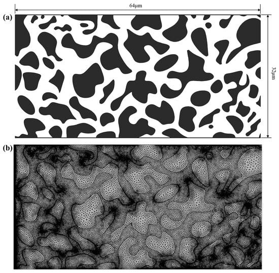
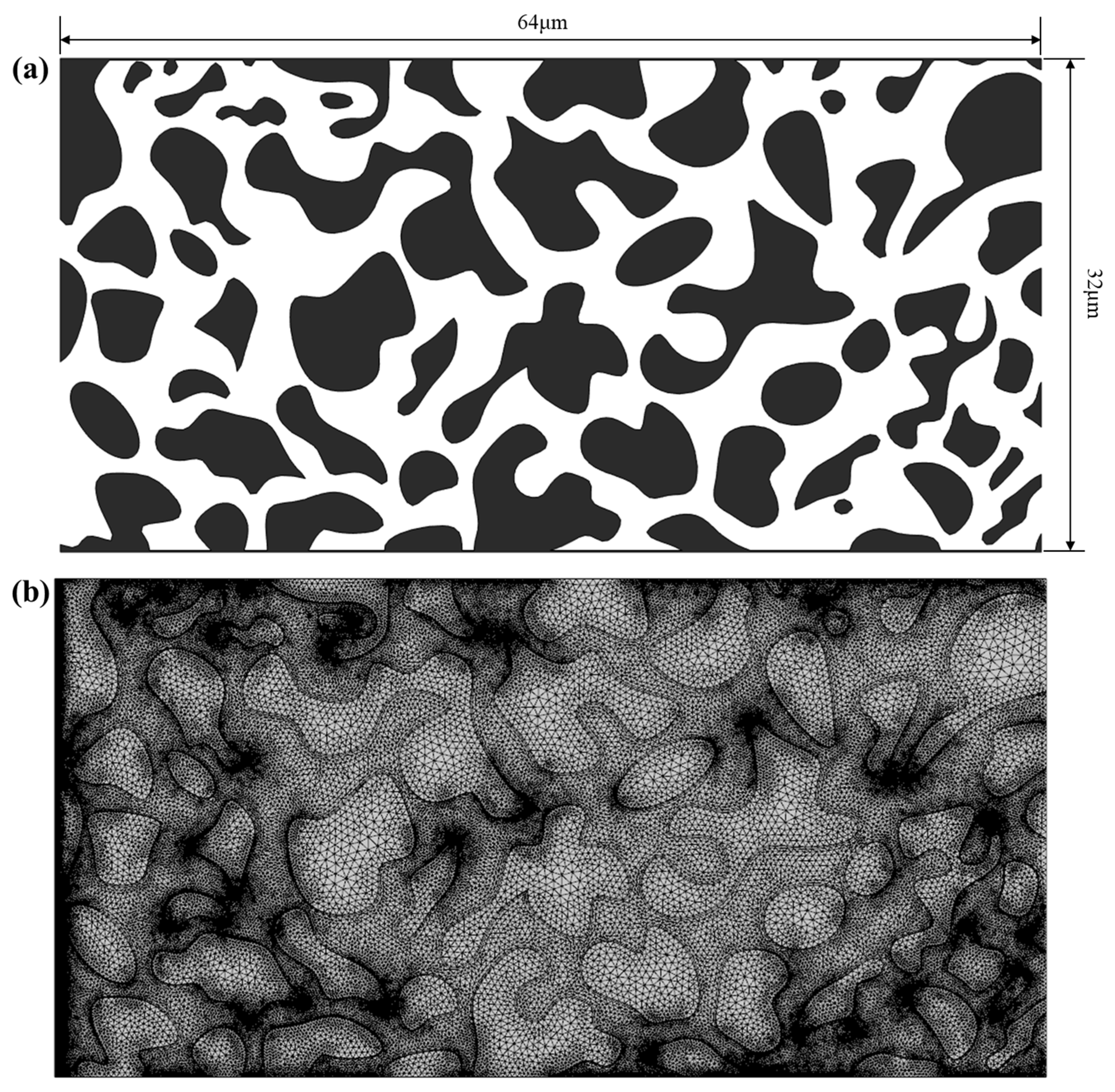
The porous medium geometry used in this study is based on a scanning electron microscopy (SEM) image of a real porous medium described by Keller et al. [28], which has been widely adopted for modeling two-phase flow in porous media. It should be noted that the geometry used here is not the full 509 × 509 μm domain reported in Ref. [28], and it is also not a local fragment extracted from that domain. Instead, the same porous structure pattern was adopted, while the overall physical dimensions were rescaled for the present simulations. The computational domain covers an area of 64 μm × 32 μm with a thickness of approximately 1 μm, as shown in Figure 1a. The corresponding finite element mesh is shown in Figure 1b. This rescaling was intended to retain the essential pore–throat connectivity and heterogeneous structural features of the adopted geometry while keeping the computational cost of the coupled non-isothermal two-phase flow simulation within a reasonable range. Since the present model is two-dimensional, this thickness is treated as the equivalent out-of-plane thickness and is used in the heat-transfer calculation to account for the finite thickness of the representative pore channel. The CO2 injection temperature and reservoir temperature in this study are set within the range of 293.15 K to 363.15 K, representative of actual subsurface reservoir conditions over a broad range of operating scenarios. Previous studies have shown that injected CO2 may enter the formation at a temperature significantly lower than the reservoir temperature, while typical geothermal gradients also support reservoir temperatures in this range for kilometer-scale burial depths [34]. CO2 is injected into the porous structure at a constant injection rate; the initial pressure and outlet boundary pressure are both set to 1 MPa. It should be noted that this pressure is used here as a reference pressure boundary condition in the pore-scale, velocity-controlled model, rather than as an attempt to reproduce the actual in situ reservoir pressure [35]. To suppress unstable flow and ensure model convergence at the initial time step, a step function rising from 0 to 1 over a very short time interval (0.001 s) is applied to the inlet boundary condition. Furthermore, to ensure the accuracy of simulation results, the Boussinesq approximation is not adopted in this study (the Boussinesq approximation considers density as a function of temperature only in the buoyancy term of the momentum equation, treating density as constant elsewhere, in order to reduce computational cost).
Figure 1.
Geometry of the porous medium and corresponding finite element mesh used for the two-phase flow simulations: (a) porous medium geometry, where black regions represent the solid matrix and white regions represent the pore space; (b) finite element mesh of the computational domain. The left boundary is the inlet and the right boundary is the outlet.
In this study, the mesh consists of triangular and quadrilateral elements. To ensure computational accuracy, boundary layer meshes are refined near solid walls. Adaptive mesh refinement is also employed to achieve numerical accuracy at a reasonable computational cost. In the process of resolving the two-phase interface using the PFM, the mobility tuning parameter (χ) is a critical parameter that affects the accuracy of results. The value of χ must be moderate in order to maintain a constant interface thickness and preserve the convective motion of both phases. Studies have shown that for two-phase flow simulations, χ should be kept in the range of 0.1 to 1, and that χ = 1 yields smaller volume shrinkage and more physically realistic results. Accordingly, χ = 1 is adopted throughout this study. All simulations were implemented in COMSOL Multiphysics 6.0, in which the coupled governing equations and boundary conditions were established. The MUMPS direct solver used in this study refers to the direct linear solver integrated in COMSOL Multiphysics, which was employed to ensure numerical robustness and solution convergence. The simulation results were further postprocessed and visualized in COMSOL Multiphysics to obtain the phase-field distributions, flow-field patterns, viscosity fields, and saturation evolution curves presented in this manuscript.
3. Results and Discussion
3.1. Model Validation
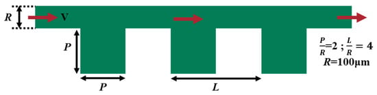
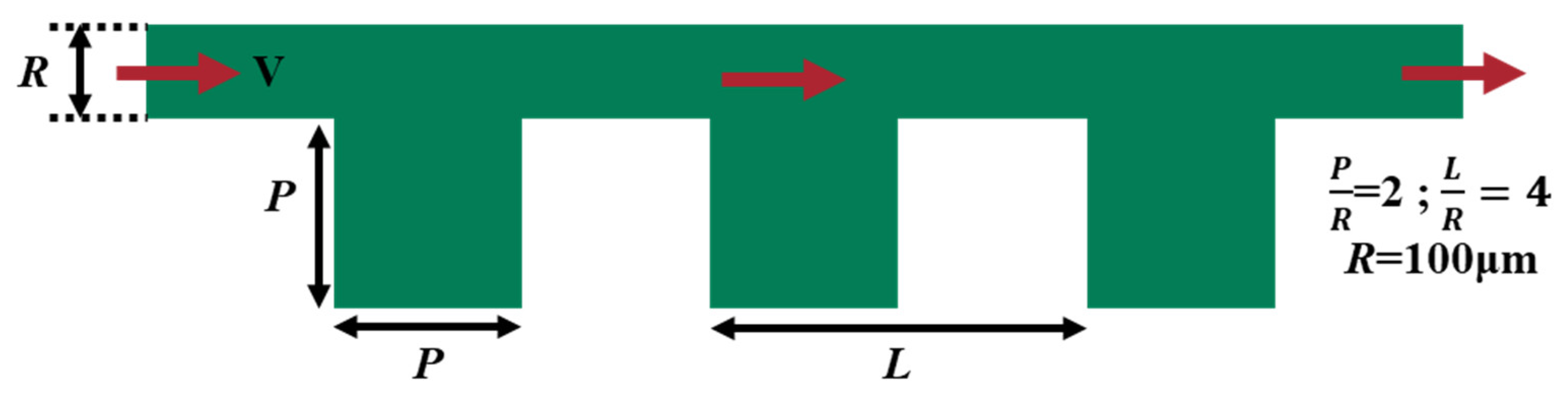
To validate the numerical framework used in this study, the simulation results were compared against the experimental work of Roman et al. [36], who investigated phase-trapping phenomena in a two-dimensional dead-end pore micro-model (i.e., an eddy pocket), as shown in Figure 2. In their experiment, the microchannel was initially saturated with the wetting phase, consisting of 20% deionized water and 80% glycerol, while the non-wetting phase was silicone oil. The viscosity of the wetting phase and non-wetting phase was 49.00 mPa·s and 4.60 mPa·s, respectively, corresponding to a viscosity ratio of 0.09. The interfacial tension between the two phases was approximately 14 mN/m, the injection rate was 1.45 mm/s, and the wettability condition corresponded to a contact angle of 45°. Since the benchmark experiment of Roman et al. [36] was conducted under an isothermal condition, the corresponding validation simulation in the present study was also performed under an isothermal two-phase flow condition, without imposing an additional temperature gradient.
Figure 2.
Two-dimensional eddy pocket microchannel model established in the experiment of Roman et al. [36], in which the arrow represents flow direction.
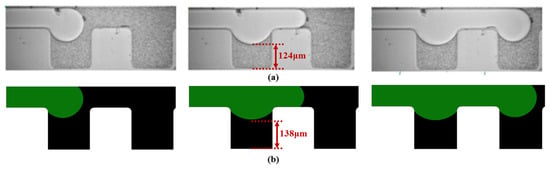
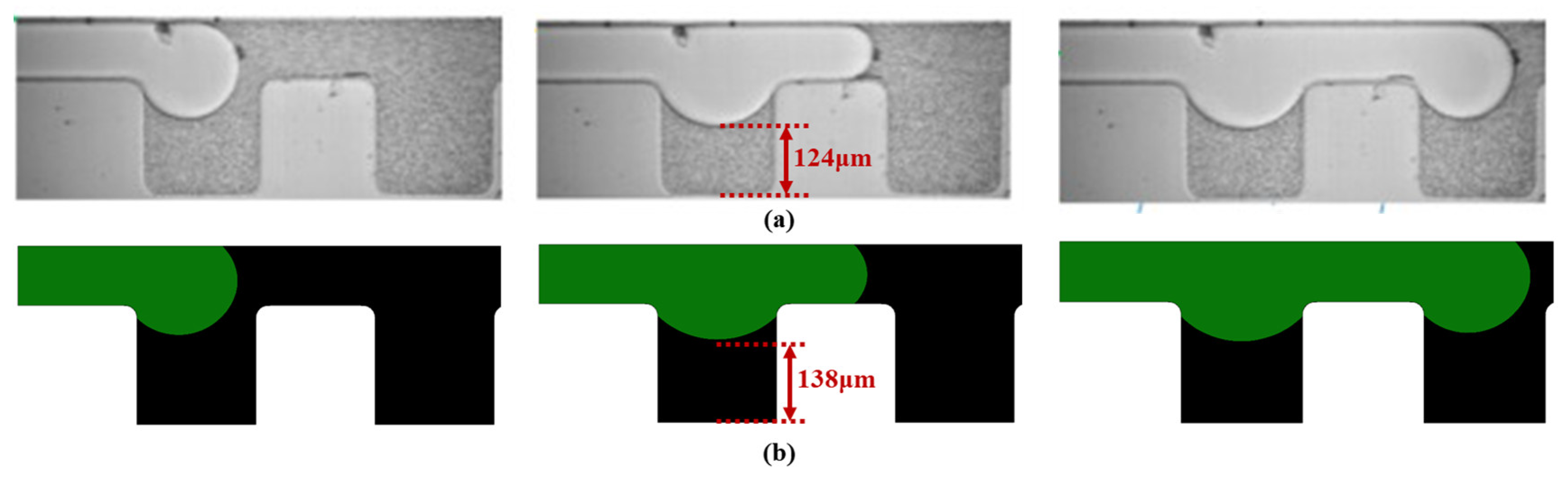
As shown in Figure 3, good agreement was achieved between the simulated and experimental phase distributions in the eddy pocket. The distance from the center of the meniscus to the bottom of the eddy pocket was measured as 124 μm in the experiment and 138 μm in the simulation, indicating that the model can reasonably reproduce the pore-scale interfacial configuration and phase-trapping behavior observed in the benchmark experiment. It should be noted that the present validation mainly supports the pore-scale hydrodynamic and interface-capturing capability of the model. The direct applicability of the present simulations to field-scale reservoirs remains limited, and further validation with dedicated non-isothermal experiments and field-related data is needed in future work.
Figure 3.
Comparison of experimental and simulation results: (a) experimental result, in which the white fluid represents the non-wetting phase and the gray region is filled with the wetting phase; (b) simulation result, in which green represents the non-wetting phase and black represents the wetting phase.
3.2. Effect of Injection Rate on Flow in Porous Media
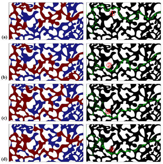
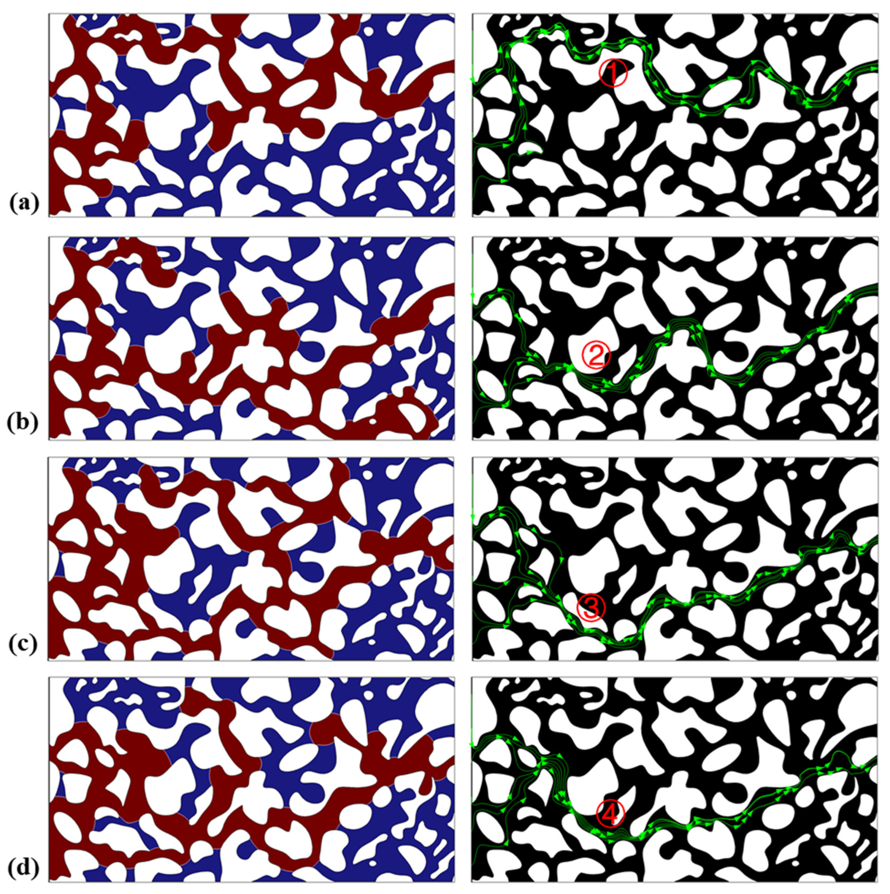
Figure 4 presents a comparison of the two-phase fluid distribution and flow pathways at steady-state displacement under different injection rates. In this case, the contact angle is 2π/3, and the injection temperature and reservoir temperature are 313.15 K and 363.15 K, respectively. As shown in Figure 4a, at an injection rate of 50 μm/s, a single dominant flow pathway ① is established after displacement reaches steady state. In contrast, at an injection rate of 150 μm/s, the flow shifts to a new preferential pathway ② and additionally breaks through several smaller branch channels. When the injection rate is further increased to 250 μm/s, CO2 invades a greater number of pores and pore throats, the main flow channel shifts to pathway ③, and the number of flow branches near the inlet increases further. At an injection rate of 350 μm/s, the main flow channel shifts again, while the number of flow branches actually decreases. These observations indicate that injection rate exerts a significant influence on the preferential flow pathways of two-phase flow. A moderate increase in injection rate is conducive to the development of additional flow branches and an expanded CO2 sweep area.
Figure 4.
Phase-field distribution (left, blue: oil, brown: CO2) and flow field distribution (right, arrow represents flow line) in the porous medium model at steady-state displacement under different injection rates: (a) 50 μm/s, (b) 150 μm/s, (c) 250 μm/s, (d) 350 μm/s.
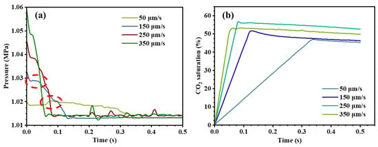
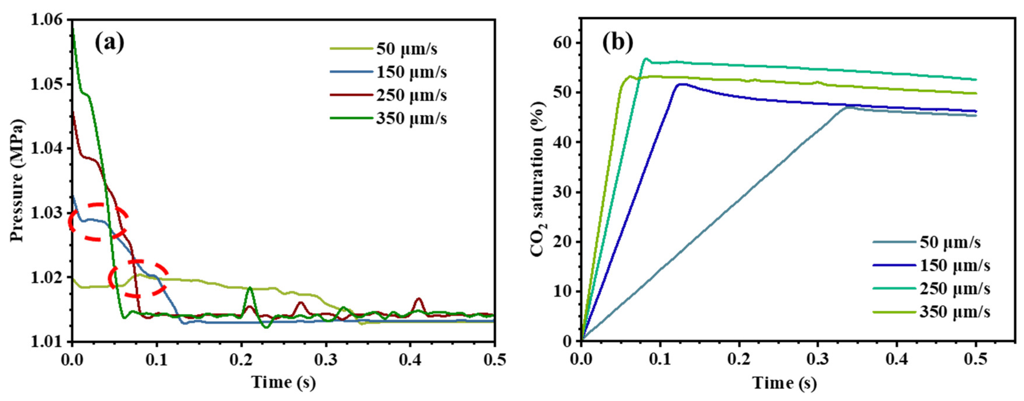
The injection pressure during CO2–crude oil displacement at different injection rates is shown in Figure 5a. As the injection rate increases from 50 μm/s to 350 μm/s, the initial displacement pressure increases progressively. Higher displacement pressure is beneficial for mobilizing crude oil trapped in smaller pore throats. During non-isothermal CO2–crude oil displacement, a decrease in crude oil temperature leads to an increase in oil viscosity, which in turn raises the displacement pressure, as indicated by the red dashed box in Figure 5a. It is worth noting that when the CO2 injection rate exceeds a certain critical value, the additional displacement resistance caused by the increase in oil viscosity is overcome.
Figure 5.
CO2–oil displacement simulation results under different injection rates: (a) injection pressure curves; (b) evolution of CO2 saturation.
Figure 5b presents a comparative analysis of CO2 saturation under different injection rates. It is found that, at a given injection temperature, the CO2 saturation in each case is directly related to the injection rate. As the injection rate increases from 50 μm/s to 250 μm/s, CO2 saturation rises from 45.35% to 55.98%. However, when the injection rate is further increased to 350 μm/s, CO2 saturation decreases to 49.81%. These results indicate that increasing the injection rate within a certain range enables CO2 to break through smaller pore throats, thereby enhancing the overall sweep efficiency and improving oil recovery. However, an excessively high injection rate leads to pronounced non-piston-like displacement and premature fluid breakthrough, which ultimately reduces oil recovery. A gradual decline in CO2 saturation over time is also observed, attributed to backflow phenomena in two-phase flow within porous media; this backflow effect diminishes progressively as the injection rate increases [1]. Key displacement outcome parameters under different injection rates are summarized in Table 1. From an engineering perspective, these results suggest that the injection rate should be maintained within a moderate range rather than increased excessively. Under the present simulation conditions, an injection rate in the range of 150–250 μm/s provides a better balance between displacement pressure and sweep efficiency, because it enables CO2 to invade more pore throats and lateral branches while avoiding severe premature breakthrough. In contrast, although a higher injection rate can increase the initial driving force, an excessively high rate such as 350 μm/s leads to more pronounced non-piston-like displacement and earlier channeling, which reduces the overall displacement efficiency. Therefore, in practical CO2 flooding design, simply increasing the injection rate is not always beneficial, and an optimized moderate rate is preferable for improving microscopic sweep performance.
Table 1.
Key parameters of the displacement outcomes at various injection rates.
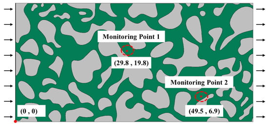
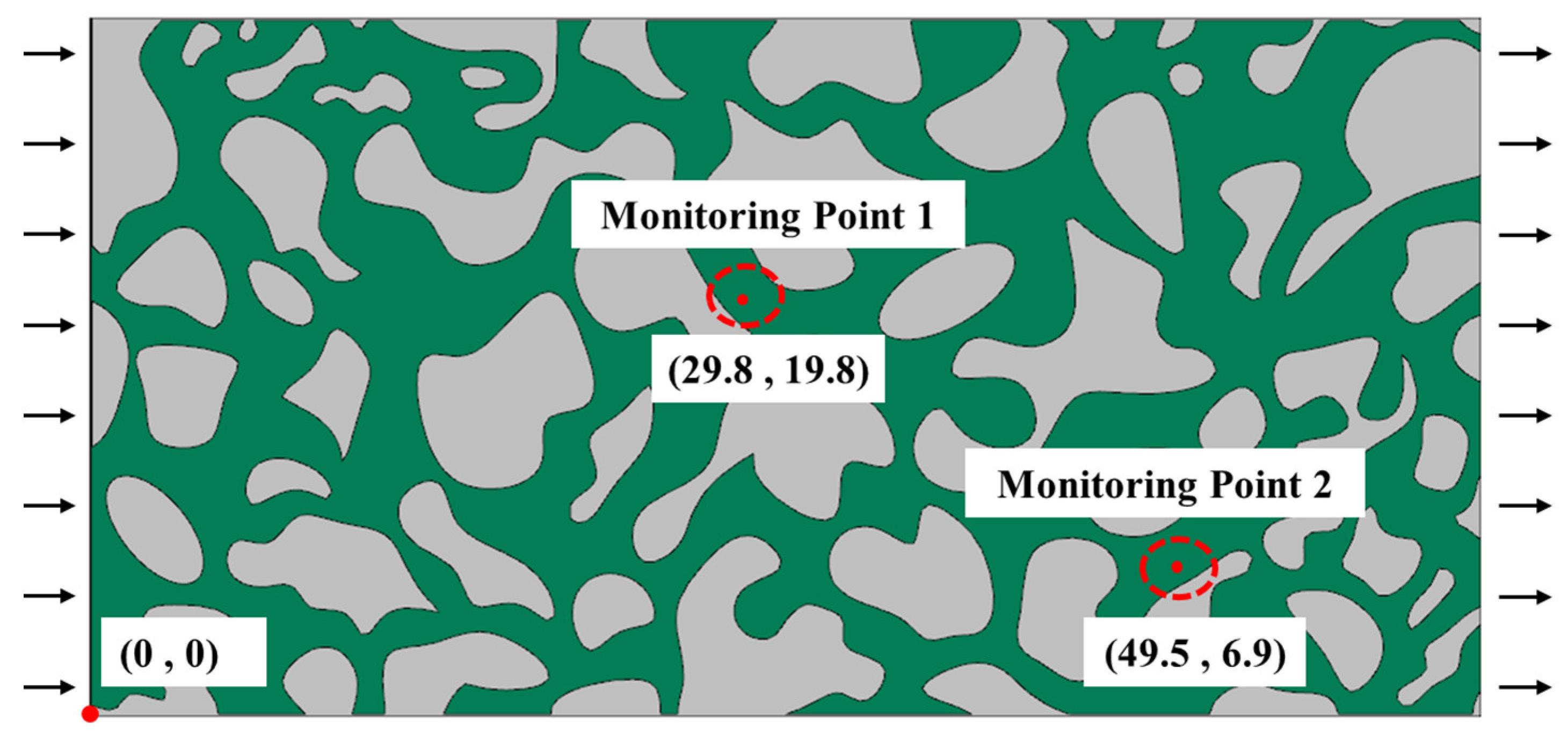
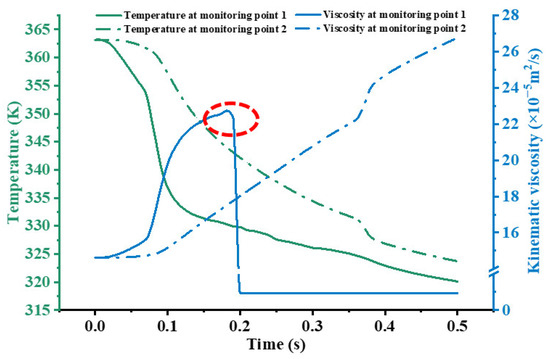
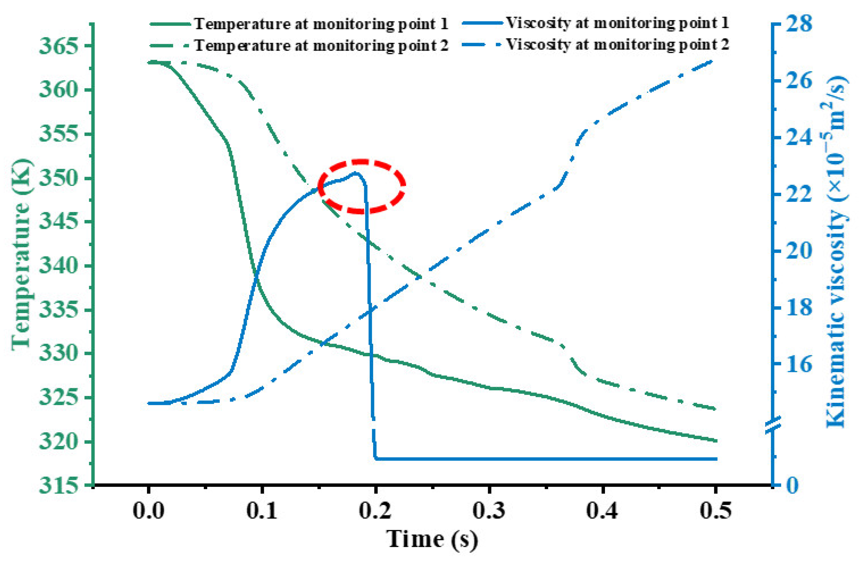
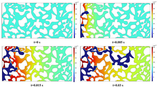
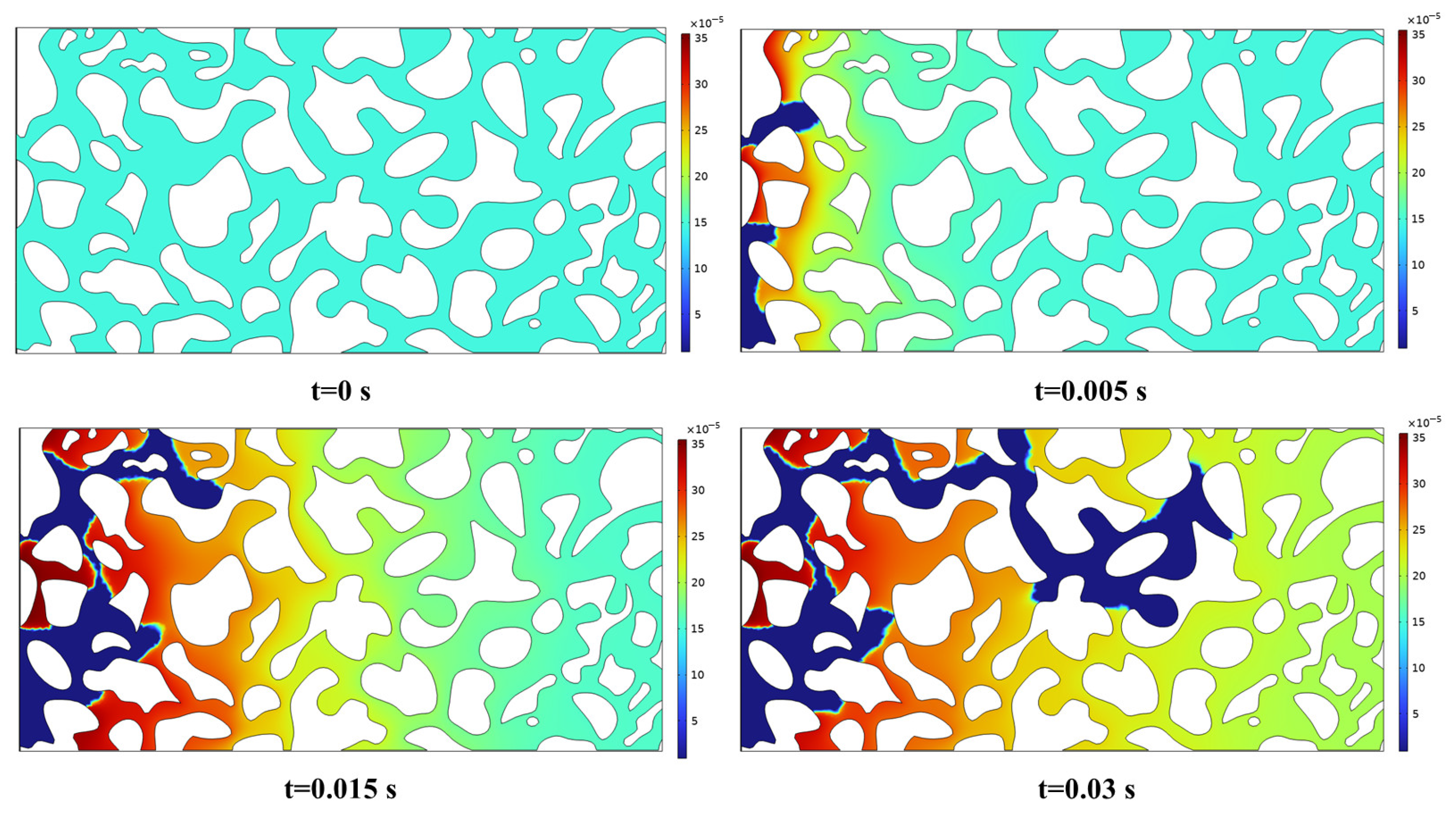
To further clarify the effect of temperature on the flow characteristics of non-isothermal two-phase flow in porous media, two fluid property monitoring points were established in the model, the locations of which are shown in Figure 6. Figure 7 presents the temporal evolution of temperature and fluid viscosity at the monitoring points. As CO2 flows through the porous medium and heat exchange occurs between CO2 and crude oil, or between CO2 and the solid matrix, the crude oil temperature gradually decreases and the oil viscosity correspondingly increases. A sharp change in viscosity is observed at monitoring point 1 at approximately t = 0.2 s (highlighted by the red dashed box in Figure 7), which is attributed to CO2 displacement of the crude oil at that location—the viscosity of CO2 being significantly lower than that of crude oil. Figure 8 presents visualizations of the viscosity field at different time steps under conditions of injection temperature 313.15 K, reservoir temperature 363.15 K, and injection rate 50 μm/s. The results demonstrate that during two-phase seepage, the viscosity of the displacing phase (CO2) changes relatively little, whereas the viscosity of the displaced phase (crude oil) increases progressively as temperature decreases. It can therefore be inferred that changes in the viscosity ratio between the displacing and displaced phases—caused by heat transfer—may be an important factor governing immiscible two-phase interfacial dynamics and two-phase flow characteristics in heterogeneous porous structures.
Figure 6.
Schematic diagram of fluid property monitoring point locations.
Figure 7.
Temporal evolution of temperature and fluid viscosity at the monitoring points.
Figure 8.
Time evolution of the fluid viscosity field in the model under specific conditions.
3.3. Effect of Injection Temperature on Flow in Porous Media
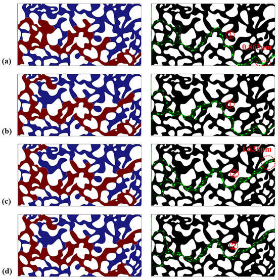
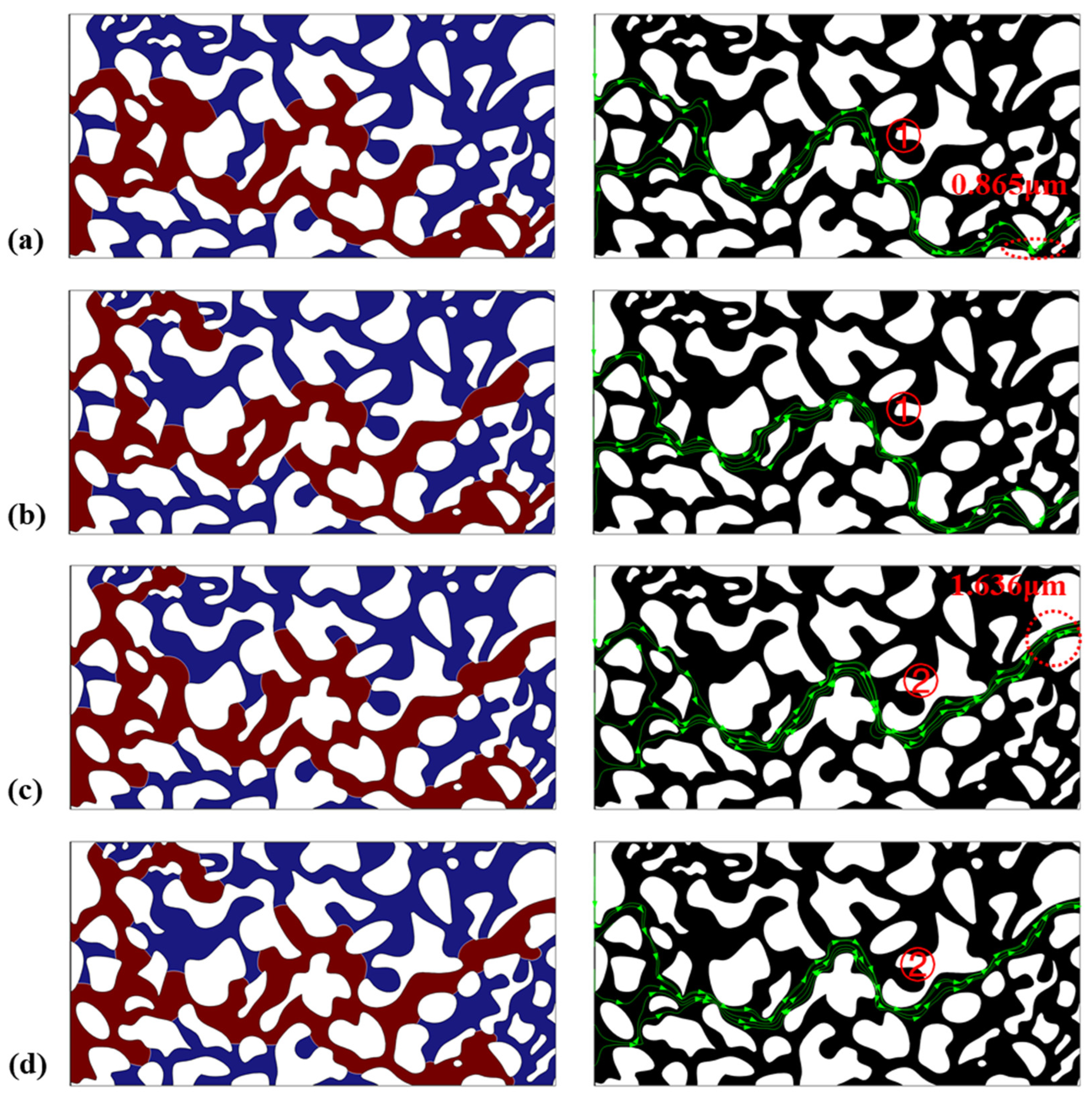
Figure 9 shows the two-phase flow morphology and flow pathways at steady-state displacement under different CO2 injection temperatures, with a reservoir temperature of 363.15 K and an injection rate of 150 μm/s. Compared to an injection temperature of 293.15 K, increasing the injection temperature causes CO2 to occupy a greater number of small branch channels at the leading front of the model, with viscous fingering occurring at the middle-to-late stages of displacement. Conversely, a lower injection temperature results in pronounced viscous fingering at the early stage of displacement. It can also be observed that as injection temperature increases, the preferential flow pathway of CO2 undergoes a notable shift: beyond a certain injection temperature threshold, the main flow channel transitions from smaller pore throats (average throat width: 0.864 μm) to larger pore throats (average throat width: 1.636 μm). A comparison of the four injection temperatures reveals that although the CO2 distribution in the central region of the model is broadly similar across cases, higher injection temperatures enhance the utilization of lateral pore channels at both the leading and trailing ends of the model, promoting a more uniform flow distribution. This is attributed to the reduction in the CO2-to-crude oil mobility ratio resulting from the elevated injection temperature. It is evident that injection temperature exerts a significant influence on both the main flow channels and local flow pathways within the porous structure, and it is precisely the breakthrough of these local branch channels that leads to higher CO2 saturation (Figure 10).
Figure 9.
Phase-field distribution (left, blue: oil, brown: CO2) and flow field distribution (right, arrow represents flow line) in the model at steady-state displacement under different injection temperatures: (a) 293.15 K, (b) 323.15 K, (c) 343.15 K, (d) 363.15 K.
Figure 10.
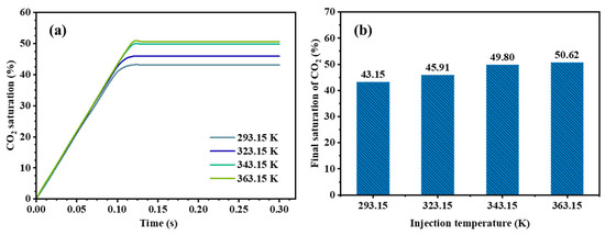
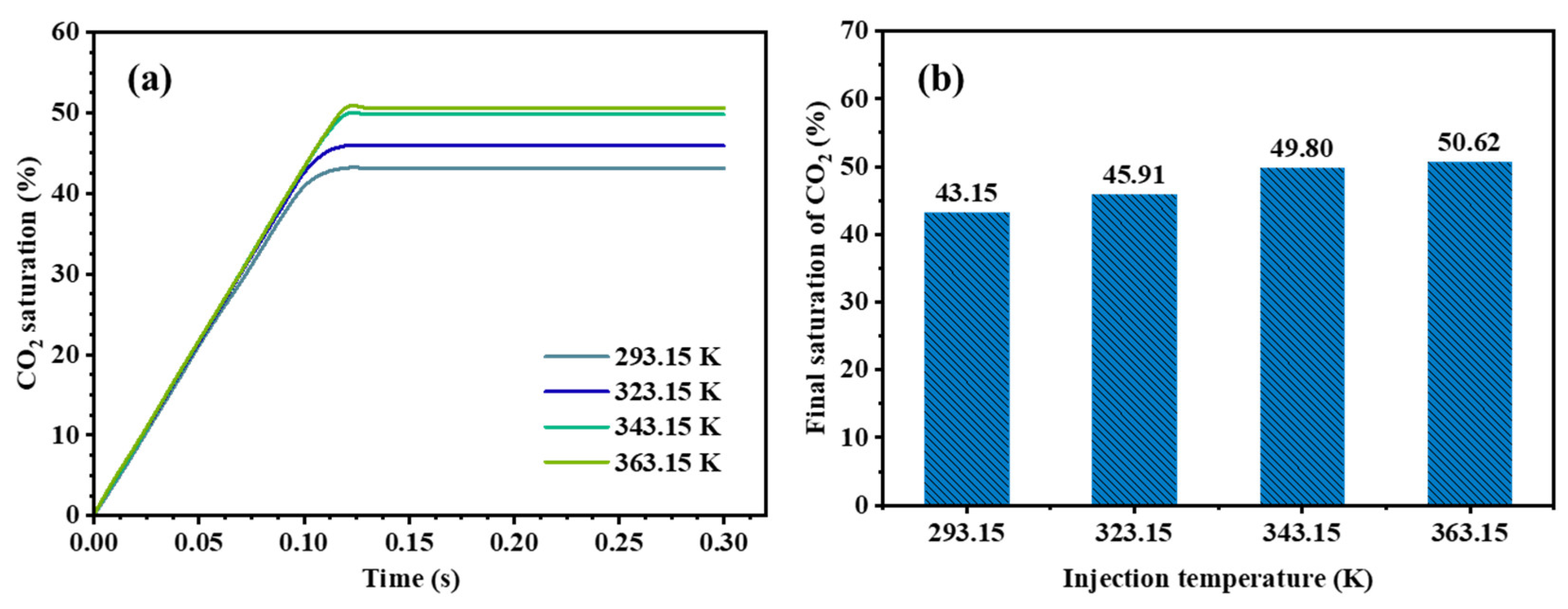
CO2–oil displacement results under different injection temperatures: (a) evolution of CO2 saturation during displacement; (b) CO2 saturation after reaching steady-state displacement.
As shown in Figure 10b, the CO2 saturations under the four injection temperatures are approximately 43.15%, 45.91%, 49.80%, and 50.62%, respectively. Compared to the case at 293.15 K, increasing the injection temperature prolongs the CO2 breakthrough time, increases the number of local branch channels, and raises CO2 saturation, with a maximum difference of approximately 0.0747. It is worth noting that, under a fixed reservoir temperature, when the injection temperature exceeds a certain threshold, further increases in injection temperature result in only marginal changes in CO2 saturation—rising from 49.80% at 70 °C to 50.62% at 90 °C, an increase of approximately 1.62%. Therefore, moderately increasing the injection temperature of the displacing phase can improve the viscosity ratio, enhance the utilization of lateral pore channels, promote a more uniform flow distribution, and ultimately improve overall displacement efficiency. These results also have practical implications for thermal management during CO2 injection. Under the present simulation conditions, increasing the injection temperature helps reduce the unfavorable mobility ratio between CO2 and crude oil, promotes the utilization of lateral pore channels, and improves displacement uniformity. However, the results also indicate that the improvement is not linear with temperature. For example, although the steady-state CO2 saturation increases from 43.15% to 50.62% as the injection temperature rises from 293.15 K to 363.15 K, the increase from 343.15 K to 363.15 K is only 1.62%. This suggests that, for practical applications, a moderately elevated injection temperature may already capture most of the displacement benefit, whereas further heating may provide only limited additional improvement while increasing operational cost.
3.4. Effect of Wettability on Flow in Porous Media
Wettability is typically characterized by the contact angle (θ), which influences interfacial curvature and capillary pressure, thereby controlling the interfacial morphology of immiscible two-phase flow [37]. A water-wet medium is generally defined as one where θ < π/2, while θ > π/2 indicates an oil-wet surface. This section discusses the effect of wettability on CO2–crude oil displacement at an injection rate of 150 μm/s, a reservoir temperature of 363.15 K, and an injection temperature of 353.15 K.
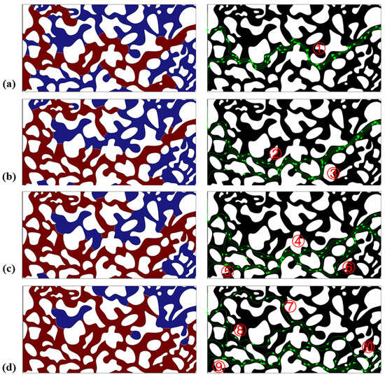
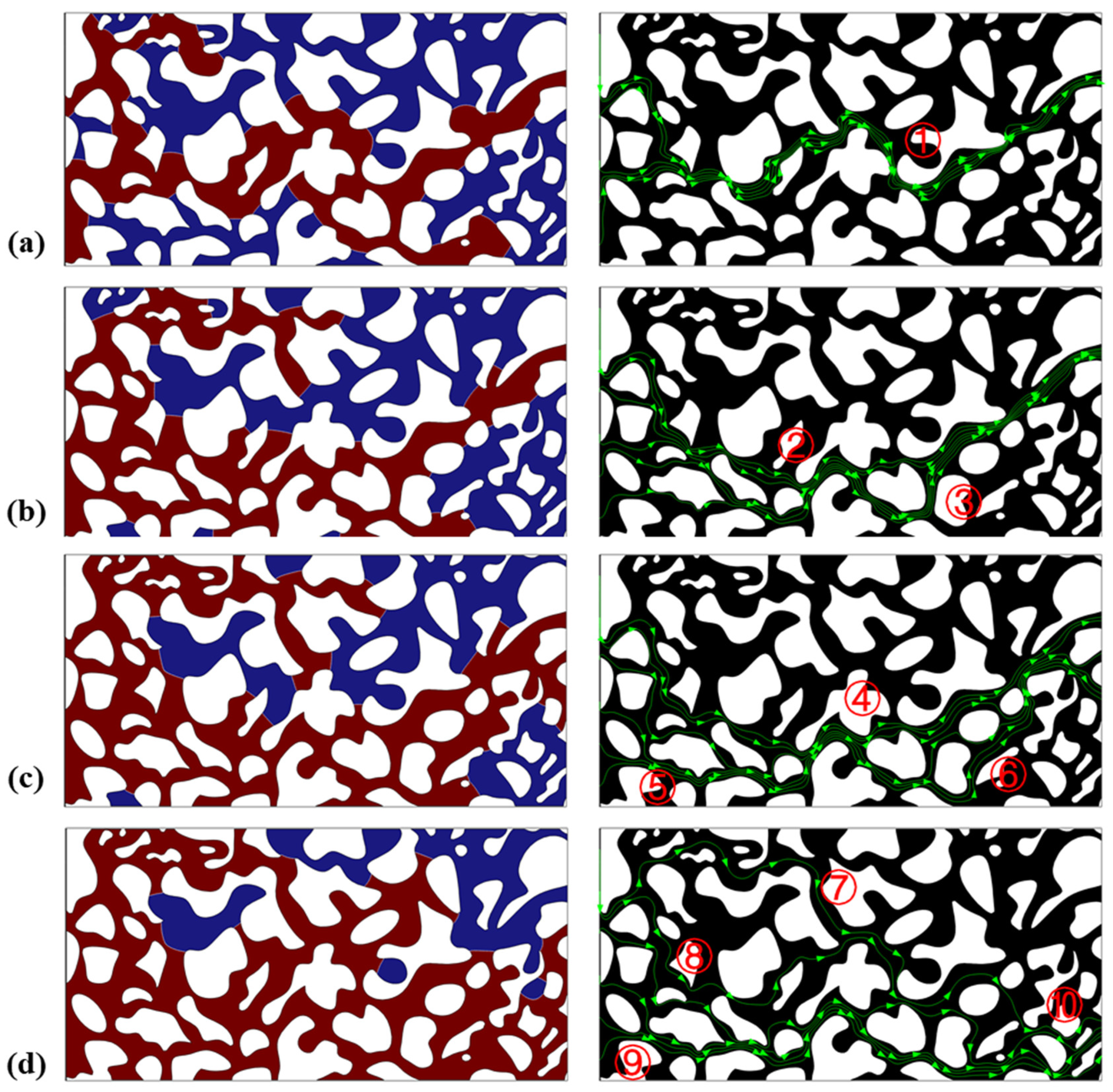
Figure 11 presents the steady-state fluid distributions and main flow pathways for four contact angles—π/3, 5π/12, π/2, and 2π/3—corresponding to water-wet, weakly water-wet, neutral-wet, and oil-wet conditions, respectively. In general, as the water-wetness of the medium increases, residual oil saturation decreases, as illustrated in Figure 11. Under oil-wet conditions (θ = 2π/3), CO2 advances toward the displacement front as three continuous fingers, with the middle finger breaking through the boundary while the two lateral fingers stagnate after the middle finger has broken through; the finger on the upper side of the medium is notably shorter. Large quantities of residual oil of varying volumes are observed at different locations within the medium after displacement stabilization, and only a single fingering main channel ① is present. The steady-state two-phase fluid distribution and main flow channel under oil-wet conditions exhibit strong heterogeneity. Under neutral-wet conditions (θ = π/2), the two-phase fluid distribution is broadly similar to that of the oil-wet case, with CO2 again advancing as three continuous fingers; however, the upper finger advances further toward the outlet boundary, the main fingering channel shifts, and CO2 flows along two primary channels (② and ③). Under water-wet conditions (θ = 5π/12 and π/3), CO2 advances as two continuous fingers, with the finger at the bottom of the medium being thicker and eventually breaking through the outlet boundary. A thinner, longer finger forms in the upper region of the medium and ceases to advance after the lower finger has broken through. As water-wetness increases, the CO2 seepage pathway transitions from a few dominant channels to multiple dispersed channels, resulting in a more uniform flow distribution. At θ = π/3, the number of main seepage channels reaches four (⑦, ⑧, ⑨, and ⑩).
Figure 11.
Phase-field distribution (left, blue: oil, brown: CO2) and flow field distribution (right, arrow represents flow line) in the model at steady-state displacement under different contact angles: (a) 2π/3, (b) π/2, (c) 5π/12, (d) π/3.
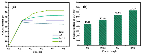
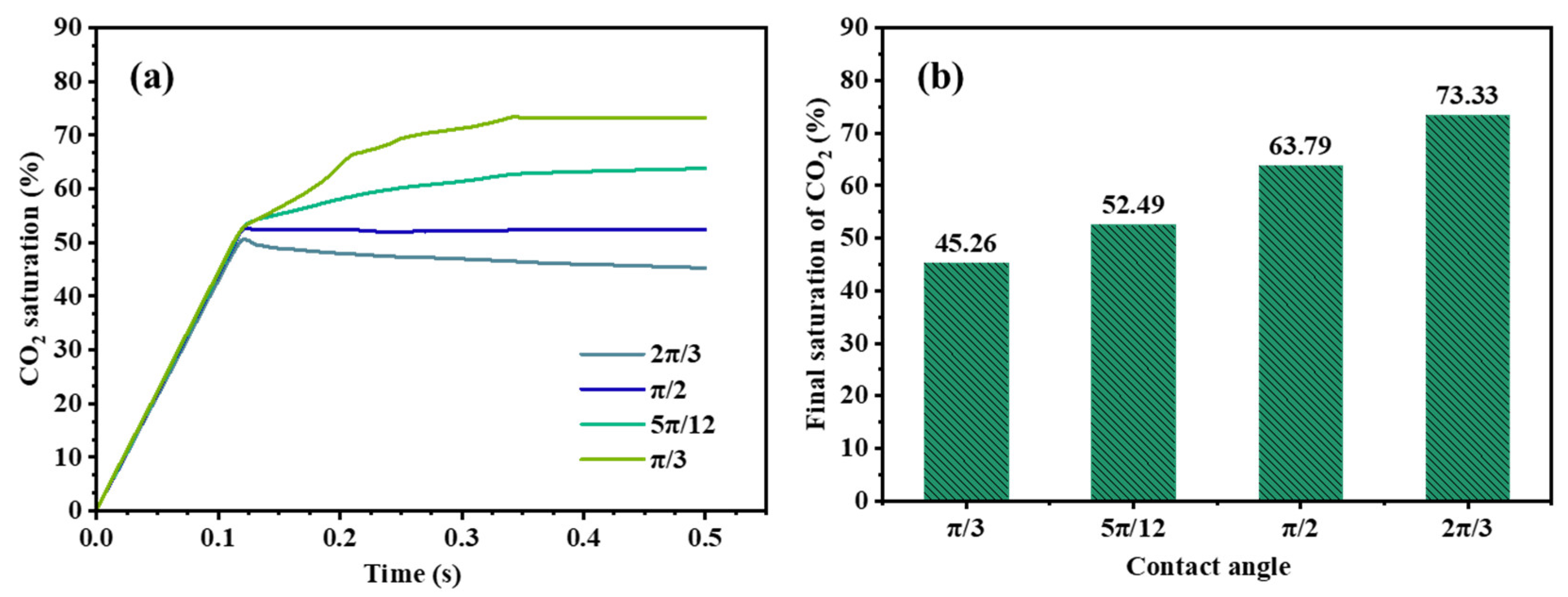
The evolution of CO2 saturation during CO2–crude oil displacement under different wettability conditions is shown in Figure 12a. The weaker the oil-wetness of the medium, the higher the CO2 saturation, which is consistent with findings widely reported in the literature [38,39]. Under oil-wet conditions (θ = 2π/3), CO2 saturation at steady state is only 45.26%; when the contact angle is reduced to π/3, CO2 saturation increases by more than 28% (Figure 12b). It is also notable that as oil-wetness increases, CO2 breakthrough occurs earlier. For example, the breakthrough times for media with contact angles of θ = π/3 and θ = 2π/3 are 0.34 s and 0.12 s, respectively. This implies that, in reservoirs where wettability alteration is feasible, shifting the rock surface toward a weakly water-wet or strongly water-wet state would be beneficial for suppressing dominant fingering flow, promoting a more distributed flow pattern, and improving microscopic oil displacement efficiency.
Figure 12.
CO2–oil displacement results under different wettability conditions: (a) evolution of CO2 saturation during the displacement process; (b) steady-state CO2 saturation after stabilization.
4. Conclusions
The present study employs COMSOL Multiphysics to simulate non-isothermal CO2–crude oil displacement in heterogeneous porous structures, based on a coupled model integrating the Cahn–Hilliard phase-field equation, the Navier–Stokes equations, and the heat transfer equation. The effects of injection rate, injection temperature, and wettability on two-phase flow characteristics are systematically investigated. The main conclusions are as follows:
- (1)
- During non-isothermal two-phase displacement, changes in the viscosity ratio between the displacing and displaced phases—induced by heat transfer—may be an important factor governing immiscible two-phase interfacial dynamics and two-phase flow characteristics in heterogeneous porous structures.
- (2)
- Within a certain range, increasing the injection rate of the displacing phase enables CO2 to break through smaller pore throats and expand the sweep area, thereby improving oil recovery. For example, the steady-state CO2 saturation increased from 45.35% to 55.98% as the injection rate increased from 50 to 250 μm/s, but decreased to 49.81% at 350 μm/s. However, an excessively high injection rate intensifies non-piston-like displacement and leads to premature CO2 breakthrough, which is detrimental to displacement efficiency.
- (3)
- During non-isothermal CO2–crude oil displacement, injection temperature significantly affects both the main flow channels and local flow pathways within the porous structure. The steady-state CO2 saturation increased from 43.15% to 50.62% as the injection temperature increased from 293.15 K to 363.15 K. Moderately increasing the injection temperature of the displacing phase improves the viscosity ratio, enhances the utilization of lateral pore channels, promotes a more uniform flow distribution, and ultimately improves overall displacement efficiency.
- (4)
- Compared to weakly water-wet porous media, strongly water-wet systems exhibit a transition of CO2 seepage pathways from a few dominant channels to multiple dispersed channels, resulting in a more uniform flow distribution. In particular, the steady-state CO2 saturation increased by more than 28% when the contact angle decreased from 2π/3 to π/3. Furthermore, CO2 breakthrough is delayed and the steady-state CO2 saturation after displacement stabilization is higher.
It should be noted that the present validation mainly supports the pore-scale hydrodynamic and interface-capturing capability of the model under isothermal benchmark conditions (Section 3.1). In addition, the present model is developed for immiscible non-isothermal CO2–oil two-phase flow and does not explicitly consider chemical interactions or detailed compositional/thermodynamic phase behavior (Section 2.1), which could be addressed in future work.
Author Contributions
Conceptualization, P.S. and K.Y.; methodology, L.D.; software, L.D.; validation, C.Q., L.D. and W.J.; formal analysis, C.X.; investigation, C.X.; resources, L.D.; data curation, L.D.; writing—original draft preparation, P.S. and L.D.; writing—review and editing, P.S.; visualization, W.J.; supervision, C.Q.; project administration, K.Y.; funding acquisition, C.Q. All authors have read and agreed to the published version of the manuscript.
Funding
This research received no external funding.
Data Availability Statement
Data will be made available on request.
Conflicts of Interest
Authors Pinghua Shu, Kairui Ye, Chao Qian and Wei Jiang were employed by the PetroChina Southwest Oil and Gas Field Company, Chao Xu was employed by the CNPC Chuanqing Drilling Engineering Co., Ltd. The remaining author declares that the research was conducted in the absence of any commercial or financial relationships that could be construed as a potential conflict of interest.
References
- Liu, J.; Ju, Y.; Zhang, Y.; Gong, W.; Chang, W. Thermal-hydro coupling model of immiscible two-phase flow in heterogeneous porous structures at high temperatures. Int. J. Therm. Sci. 2020, 156, 106465. [Google Scholar] [CrossRef] [Scilit]
- Amiri, H.A.; Hamouda, A. Pore-scale modeling of non-isothermal two phase flow in 2D porous media: Influences of viscosity, capillarity, wettability and heterogeneity. Int. J. Multiph. Flow 2014, 61, 14–27. [Google Scholar] [CrossRef] [Scilit]
- Cai, P.; Que, Y.; Xie, X.; Xue, B. Numerical study on two-phase seepage characteristics in porous media considering wall wettability. J. Wuhan Univ. (Eng. Sci.) 2023, 56, 414–420. (In Chinese) [Google Scholar]
- Ji, Y.; Wang, L.; Han, H.; Jiang, G.; Wang, Z. Study on microscopic flow characteristics of foam in porous media. J. Southwest Pet. Univ. (Nat. Sci. Ed.) 2022, 44, 111–120. (In Chinese) [Google Scholar]
- Li, D.; Zheng, S.; Ren, C.; Zhao, X.; Pu, Y.; Chang, Z. Analysis of migration and retention of shale oil in porous media at pore scale. J. Northeast Pet. Univ. 2022, 46, 98–104. (In Chinese) [Google Scholar]
- Meakin, P.; Tartakovsky, A.M. Modeling and simulation of pore-scale multiphase fluid flow and reactive transport in fractured and porous media. Rev. Geophys. 2009, 47, RG3002. [Google Scholar] [CrossRef] [Scilit]
- Karadimitriou, N.K.; Hassanizadeh, S.M. A review of micromodels and their use in two-phase flow studies. Vadose Zone J. 2012, 11, vzj2011.0072. [Google Scholar] [CrossRef] [Scilit]
- Noiriel, C.; Soulaine, C. Pore-scale imaging and modelling of reactive flow in evolving porous media: Tracking the dynamics of the fluid–rock interface. Transp. Porous Media 2021, 140, 181–213. [Google Scholar] [CrossRef] [Scilit]
- Xiao, X.; Hu, S.; Wang, G.; Wang, G.; An, H. Effect of porosity on water–gas two-phase displacement in porous medium models. Chin. J. Nonferrous Met. 2024, 34, 1757–1767. (In Chinese) [Google Scholar]
- Xu, M.; Liu, H. Prediction of immiscible two-phase flow properties in a two-dimensional Berea sandstone using the pore-scale lattice Boltzmann simulation. Eur. Phys. J. E 2018, 41, 124. [Google Scholar] [CrossRef] [Scilit]
- Li, Z.; Galindo-Torres, S.; Yan, G.; Scheuermann, A.; Li, L. Pore-scale simulations of simultaneous steady-state two-phase flow dynamics using a lattice Boltzmann model: Interfacial area, capillary pressure and relative permeability. Transp. Porous Media 2019, 129, 295–320. [Google Scholar] [CrossRef] [Scilit]
- Gao, H.; Tatomir, A.; Karadimitriou, N.; Steeb, H.; Sauter, M. Effect of pore space stagnant zones on interphase mass transfer in porous media, for two-phase flow conditions. Transp. Porous Media 2023, 146, 639–667. [Google Scholar] [CrossRef] [Scilit]
- Nasrollahzadeh, B.; Amiri, H.A.A.; Ghabezloo, S. Pore-scale numerical modeling of coupled fluid flow and medium geometrical deformations in an unconsolidated porous medium. Eur. Phys. J. Plus 2019, 134, 596. [Google Scholar] [CrossRef] [Scilit]
- Xiao, X. Experimental Study on the Effect of Pore Structure on Water–Gas Two-Phase Displacement in Porous Media. Master’s Thesis, Jiangxi University of Science and Technology, Ganzhou, China, 2024. (In Chinese) [Google Scholar]
- Zhang, L.; Qu, S.; Wang, C.; Guan, B. Prediction of temperature field and wax deposition based on heat–fluid coupling method. J. Pet. Explor. Prod. Technol. 2019, 9, 639–644. [Google Scholar] [CrossRef] [Scilit]
- Yao, C.; Shao, Y.; Yang, J.; Huang, F.; He, C.; Jiang, Q.; Zhou, C. Effects of non-Darcy flow on heat-flow coupling process in complex fractured rock masses. J. Nat. Gas Sci. Eng. 2020, 83, 103536. [Google Scholar] [CrossRef] [Scilit]
- Zhang, X. Non-Isothermal Multiphase Multicomponent Seepage Model and Applications. Ph.D. Thesis, University of Science and Technology of China, Hefei, China, 2022. (In Chinese) [Google Scholar]
- Soulaine, C.; Creux, P.; Tchelepi, H.A. Micro-continuum framework for pore-scale multiphase fluid transport in shale formations. Transp. Porous Media 2019, 127, 85–112. [Google Scholar] [CrossRef] [Scilit]
- Alhosani, A.; Lin, Q.; Scanziani, A.; Andrews, E.; Zhang, K.; Bijeljic, B.; Blunt, M.J. Pore-scale characterization of carbon dioxide storage at immiscible and near-miscible conditions in altered-wettability reservoir rocks. Int. J. Greenh. Gas Control. 2021, 105, 103232. [Google Scholar] [CrossRef] [Scilit]
- Wang, M.; Li, L.; Zhou, Y.; Peng, X.; Yu, P.; Wang, X.; Yang, S. Experimental study on the effect of microheterogeneity on multiphase flow in a microscopic visualization model. Energy Fuels 2022, 36, 4757–4769. [Google Scholar] [CrossRef] [Scilit]
- Auset, M.; Keller, A.A. Pore-scale processes that control dispersion of colloids in saturated porous media. Water Resour. Res. 2004, 40, W03503. [Google Scholar] [CrossRef] [Scilit]
- Qin, Z.; Arshadi, M.; Piri, M. Micro-scale experimental investigations of multiphase flow in oil-wet carbonates. I. In situ wettability and low-salinity waterflooding. Fuel 2019, 257, 116014. [Google Scholar] [CrossRef] [Scilit]
- Qin, Z.; Arshadi, M.; Piri, M. Micro-scale experimental investigations of multiphase flow in oil-wet carbonates. II. Tertiary gas injection and WAG. Fuel 2019, 257, 116012. [Google Scholar] [CrossRef] [Scilit]
- Ali, H.; Soleimani, H.; Yahya, N.; Khodapanah, L.; Kozlowski, G.; Sabet, M.; Demiral, B.M.; Adebayo, L.L.; Hussain, T. Experimental investigation and two-phase flow simulation of oil and nanofluids on micro CT images of sandstone for wettability alteration of the system. J. Pet. Sci. Eng. 2021, 204, 108665. [Google Scholar] [CrossRef] [Scilit]
- Wang, L.; He, Y.; Wang, Q.; Liu, M.; Jin, X. Multiphase flow characteristics and EOR mechanism of immiscible CO2 water-alternating-gas injection after continuous CO2 injection: A micro-scale visual investigation. Fuel 2020, 282, 118689. [Google Scholar] [CrossRef] [Scilit]
- Liu, Y.; Lv, P.; Liu, Y.; Jiang, L.; Tetsuya, S.; Song, Y.; Wu, B.; Liu, S. CO2/water two-phase flow in a two-dimensional micromodel of heterogeneous pores and throats. RSC Adv. 2016, 6, 73897–73905. [Google Scholar] [CrossRef] [Scilit]
- Nuske, P.; Ronneberger, O.; Karadimitriou, N.K.; Helmig, R.; Hassanizadeh, S.M. Modeling two-phase flow in a micro-model with local thermal non-equilibrium on the Darcy scale. Int. J. Heat Mass Transf. 2015, 88, 822–835. [Google Scholar] [CrossRef] [Scilit]
- Sirivithayapakorn, S.; Keller, A. Transport of colloids in saturated porous media: A pore-scale observation of the size exclusion effect and colloid acceleration. Water Resour. Res. 2003, 39, 1109. [Google Scholar] [CrossRef] [Scilit]
- Zhao, H.; Wei, A.; Peng, H.; Zhang, K.; Chen, Y. Study on the characteristics and mechanisms of supercritical CO2 immiscible displacement in heterogeneous porous media. J. Eng. Geol. 2024, 32, 1825–1837. (In Chinese) [Google Scholar]
- Ahammad, M.J.; Alam, J.M.; Rahman, M.; Butt, S.D. Numerical simulation of two-phase flow in porous media using a wavelet based phase-field method. Chem. Eng. Sci. 2017, 173, 230–241. [Google Scholar] [CrossRef] [Scilit]
- Mirjalili, S.; Jain, S.S.; Mani, A. A computational model for interfacial heat and mass transfer in two-phase flows using a phase field method. Int. J. Heat Mass Transf. 2022, 197, 123326. [Google Scholar] [CrossRef] [Scilit]
- Yue, P.; Feng, J.J.; Liu, C.; Shen, J. A diffuse-interface method for simulating two-phase flows of complex fluids. J. Fluid Mech. 2004, 515, 293–317. [Google Scholar] [CrossRef] [Scilit]
- Norouzi, M.; Dorrani, S.; Shokri, H.; Bég, O.A. Effects of viscous dissipation on miscible thermo-viscous fingering instability in porous media. Int. J. Heat Mass Transf. 2019, 129, 212–223. [Google Scholar] [CrossRef] [Scilit]
- Loeve, D.; Hofstee, C.; Maas, J.G. Thermal effects in a depleted gas field by cold CO2 injection in the presence of methane. Energy Procedia 2014, 63, 5378–5393. [Google Scholar] [CrossRef] [Scilit]
- Bi, Y.; Wang, Y.; Zeng, C.; Liu, Y.; Xue, X.; Shi, B.; Zhong, H. Numerical simulation study on CO2 flooding in microscopic heterogeneous porous media. J. Energy Resour. Technol. Part B Subsurf. Energy Carbon Capture 2025, 1, 031006. [Google Scholar] [CrossRef] [Scilit]
- Roman, S.; Soulaine, C.; Kovscek, A.R. Pore-scale visualization and characterization of viscous dissipation in porous media. J. Colloid Interface Sci. 2020, 558, 269–279. [Google Scholar] [CrossRef] [Scilit] [PubMed]
- Khanamiri, H.H.; Slotte, P.A.; Berg, C.F. Contact angles in two-phase flow images. Transp. Porous Media 2020, 135, 535–553. [Google Scholar] [CrossRef] [Scilit]
- Dai, Y.; Zhou, Z.; Lin, J.; Han, J. Modeling of two-phase flow in rough-walled fracture using level set method. Geofluids 2017, 2017, 2429796. [Google Scholar] [CrossRef] [Scilit]
- Liu, H.; Ju, Y.; Wang, N.; Xi, G.; Zhang, Y. Lattice Boltzmann modeling of contact angle and its hysteresis in two-phase flow with large viscosity difference. Phys. Rev. E 2015, 92, 033306. [Google Scholar] [CrossRef] [Scilit]

Disclaimer/Publisher’s Note: The statements, opinions and data contained in all publications are solely those of the individual author(s) and contributor(s) and not of MDPI and/or the editor(s). MDPI and/or the editor(s) disclaim responsibility for any injury to people or property resulting from any ideas, methods, instructions or products referred to in the content. |
© 2026 by the authors. Licensee MDPI, Basel, Switzerland. This article is an open access article distributed under the terms and conditions of the Creative Commons Attribution (CC BY) license.