


Abstract
Point-the-bit rotary steerable systems (RSSs) achieve trajectory build-up through the coupled action of internal steering offset, bit attitude change, bottom hole assembly (BHA) flexure, and nonlinear wellbore interaction. Unlike conventional rigid or quasi-static BUR models, this study developed a 3D dynamic finite element model for point-the-bit RSS. The drill string was discretized using Euler–Bernoulli beam elements, with an equivalent “hinge-deflection angle” constraint introduced at the steering unit. Relative angle loading was imposed using the penalty function method, with nonlinear boundary conditions (bit–formation interaction and borehole friction) coupled into the model. Based on the established model, the effects of deflection angle, weight on bit (WOB), and rotary speed were systematically quantified. The results show that when the deflection angle increases from 0.5° to 1.5°, the average BUR rises from 1.452°/30 m to 4.251°/30 m; when the WOB increases from 60 kN to 100 kN, the average BUR increases from 2.281°/30 m to 2.814°/30 m. Within the range of 50–90 r/min, rotary speed has a limited effect on the average BUR, but it can alter the characteristics of transient fluctuations. This approach provides a robust theoretical basis for BUR evaluation, parameter optimization, and control strategy design for rotary steerable tools.
1. Introduction
With the continued development of deep and ultra-deep reservoirs and increasingly complex well architectures, precise wellbore trajectory control has become essential for improving drilling quality, reducing total cost, and maintaining operational safety and efficiency. Compared with conventional slide drilling, Rotary Steerable Systems (RSS) enable continuous drill string rotation while actively controlling inclination and azimuth, thereby improving wellbore smoothness and reducing frictional resistance [1,2]. Among the available RSS configurations, point-the-bit RSS directly reorients the bit axis through an internal biasing mechanism, producing an equivalent deflection angle and toolface-dependent steering action during rotation. Owing to this direct attitude control, point-the-bit RSS exhibits fast trajectory response and strong steering potential [3,4].
Existing studies on point-the-bit RSS have mainly proceeded along two directions. The first concerns tool architecture, steering mechanisms, and measurement control implementation [5,6]. Beyond the early clarification of operating principles, recent studies have further examined the mechanical design of RSS-related BHA components and their effects on steering behavior. For example, Wang et al. analyzed the influence of flex–sub configuration on the mechanical characteristics of RSS and showed that structural details of the steering assembly can materially affect directional performance [7]. More recently, Geng et al. reviewed the evolution of push-the-bit, point-the-bit, and hybrid RSS technologies, and highlighted the practical bottlenecks associated with steering efficiency, component reliability, and intelligent upgrading in complex shale-gas wells [8].
The second concerns steering-capacity evaluation, where build-up is the key indicator for trajectory planning, BHA design, and parameter selection. In this area, research has progressed from rock–bit-interaction-based trajectory prediction and bit steerability analysis [9,10] to RSS-oriented mathematical modeling and build-up rate (BUR) evaluation methods [11,12]. In parallel, recent studies have extended the scope from static or semi-empirical prediction toward closed-loop and intelligent control. Zafarian et al. proposed a smart RSS trajectory-tracking framework for thin-layer drilling and demonstrated the importance of reducing path-following error in complex well paths [13]. Li et al. further developed an adaptive backstepping strategy for stabilized-platform control in RSS, while Xu et al. introduced a real-time multi-input/multi-output economic model predictive control framework with sensor fusion for directional drilling, showing the growing importance of automated and control-oriented RSS applications [14,15].
The third category concerns drill string dynamics, wellbore contact, and bit–rock coupling. classical drag-bit studies have shown that drilling response can be interpreted through the coupled effects of cutting and friction, providing a useful reduced-order foundation for describing bit–rock interaction in steering analysis [16]. During drilling, continuous drill string rotation, BHA flexure, intermittent wellbore contact, and bit loading act simultaneously, often inducing coupled lateral, axial, and torsional dynamics [17,18]. Recent dynamic studies indicate that damping, borehole contact, formation interaction, and structural flexibility jointly govern the stability of near-bit motion and the transient evolution of wellbore trajectory [19,20,21,22]. In particular, Zhang et al. established a coupled drill string dynamic modeling framework using 3D field-consistent corotational beam elements, with bit–rock interaction, stabilizer effects, and wellbore contact integrated into a control-oriented formulation [23]. These studies collectively show that realistic prediction of directional behavior requires simultaneous consideration of structural flexibility, loading transfer, and nonlinear boundary effects.
The fourth category addresses sensing reliability and fault-tolerant operation of rotary steerable tools. For high-precision directional drilling, steering capability is determined not only by mechanical design and dynamic response, but also by the quality of downhole measurements and control execution. Wang et al. investigated sensor fault detection and minimum detectable fault analysis for a dynamic point-the-bit RSS, demonstrating that measurement reliability is a non-negligible factor in maintaining stable steering performance under drilling disturbances [24]. This line of research suggests that future RSS evaluation should be understood in a broader system sense, involving structure, dynamics, sensing, and control rather than only static geometric relationships.
Although these studies have significantly advanced the understanding of steering mechanisms, intelligent control, and drill string dynamics, most available BUR evaluation methods for point-the-bit RSS still rely on rigid, quasi-static, or partially coupled formulations. As a result, they cannot explicitly describe, within a unified framework, how internal steering offset is transferred through flexible BHA deformation and nonlinear wellbore constraints into both the mean BUR and its time-dependent fluctuations. This limitation becomes more pronounced in build-up sections of deep, extended-reach, and complex-structure wells, where steering efficiency, vibration suppression, and trajectory smoothness must be considered simultaneously.
To address this gap, this study develops a 3D dynamic finite element model for point-the-bit RSS. The steering unit is represented through an equivalent hinge deflection-angle constraint, while bit–rock interaction and nonlinear borehole contact/friction are incorporated into the global dynamic formulation. On this basis, the model is used to evaluate steering capacity and dynamic stability under different operating conditions. The main objectives are to
- (1)
- Construct a high-fidelity flexible dynamic model by implementing an equivalent “hinge-deflection angle” constraint at the biasing unit to accurately represent tool steering;
- (2)
- Achieve integrated dynamic coupling of the RSS-drill string assembly by incorporating bit–formation interaction and nonlinear borehole contact friction;
- (3)
- Elucidate the impacts of deflection angle, WOB, and rotational speed on BUR and stability, thereby offering critical insights for performance evaluation and operational parameter tuning.
From a practical engineering perspective, the proposed model can support pre-job evaluation of steering performance for different point-the-bit tools and BHA configurations, optimization of deflection angle–WOB–rotary speed combinations in build-up sections, and reduction of field trial-and-error during directional drilling. It therefore has direct application potential for trajectory design and parameter selection in deep, extended-reach, and complex-structure wells, where improved trajectory controllability, lower vibration risk, and reduced wellbore tortuosity are critical to drilling efficiency and safety.
2. Dynamic Analysis Model
2.1. Dynamic Equation of Whole Well Drill String
To keep the proposed dynamic finite element model computationally efficient while preserving the dominant steering physics of a point-the-bit RSS, the following assumptions are adopted. First, the drill string is treated as a slender beam undergoing small strain and small relative rotation at the element level, while the global rotation of the string about its axis is retained. Second, Euler–Bernoulli beam theory is employed; therefore, transverse shear deformation and cross-sectional warping are neglected. Third, the steering unit is represented by an equivalent rotational joint, in which translational continuity and torsional continuity are preserved, whereas prescribed relative rotations about the two lateral axes are used to describe the pointing action. Fourth, the material and sectional properties are assumed piecewise constant within each element. Fifth, the bit–rock interaction is modeled by a reduced-order interface law acting at the bit node, using averaged cutting, friction, and lateral steering actions per revolution rather than cutter-scale transient fracture processes. Finally, thermal effects, cutter wear evolution, and explicit formation anisotropy are not considered in the present formulation.
Consider a spatial beam element, e, where the local coordinate axis, x, aligns with the element centerline, and the y and z axes lie within the cross-sectional plane. Based on the Euler–Bernoulli beam theory [25] (neglecting shear deformation), each node of the two-node spatial beam element is assigned six degrees of freedom (including three translational, two lateral rotational, and one torsional). The nodal displacement vector is defined as follows:
For an element of length, Le, the displacement and rotation fields are interpolated as a linear combination of the nodal generalized coordinates using the shape function matrix, N(x):
By substituting Equation (2) into the definition of kinetic energy, the expression can be reformulated into a standard quadratic form, thereby defining the consistent element mass matrix.
where ρ is quality weight matrix.
For an Euler–Bernoulli beam characterized by small-deformation linear elasticity, the strain energy is similarly formulated as a quadratic function, from which the element stiffness matrix is derived.
where B(x) represents the strain–displacement matrix, and D denotes the material and sectional stiffness matrix.
For the distributed load p(x,t) and the concentrated nodal loads, , the virtual work done by external forces can be expressed as follows:
The element equations of motion are derived from Hamilton’s Principle, . By assembling all individual elements and applying the corresponding boundary conditions, the global dynamic equations for the entire system can be obtained [26].
where U is the global degree-of-freedom vector (comprising six degrees of freedom per node); M, K, and F are assembled from the individual element matrices Me, Ke, and fe based on their connectivity; and C is employed to characterize the engineering equivalent damping.
2.2. Development of a Dynamic Model for Point-the-Bit RSS
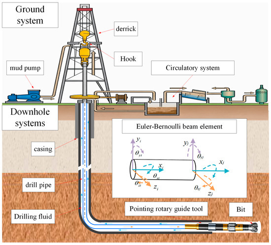
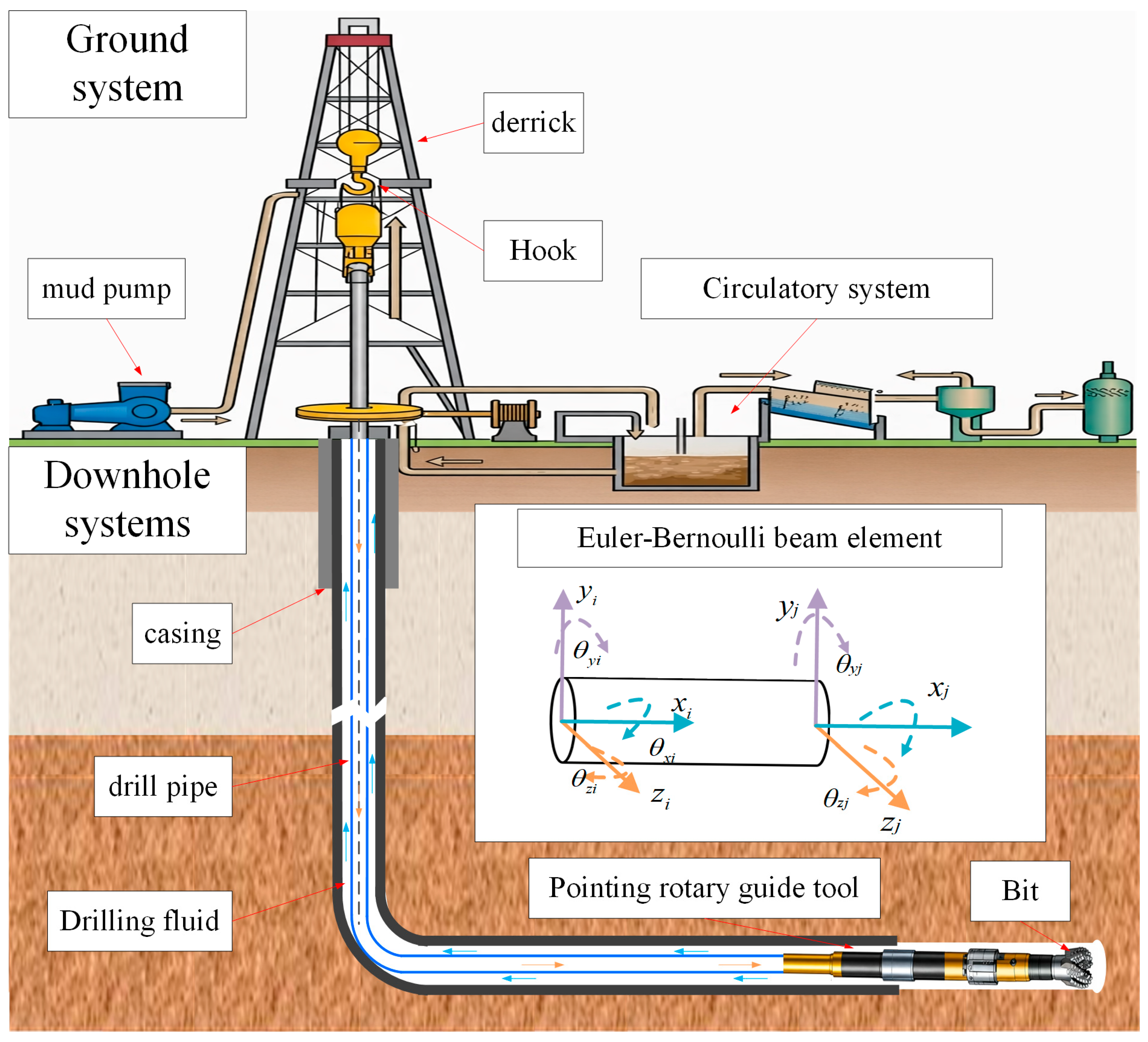
The essence of a point-the-bit RSS lies in its internal actuator, which deflects the lower drive shaft axis relative to the upper tool housing, thereby orienting the drill bit in the desired direction. This mechanism is modeled as an equivalent “rotational node” connecting the upper and lower beam elements. Within this node, continuity is maintained for translational and torsional degrees of freedom, while controlled relative rotations are permitted only along the two lateral rotational degrees of freedom. Let a and b denote the upper and lower nodes of the rotational joint, respectively (Figure 1). By concatenating the degrees of freedom of these two nodes, the generalized displacement vector for the steering segment joint is defined as follows:
where and denote the axial displacements of the upper and lower nodes, respectively; , , , and represent the lateral displacements of the two nodes; and are the torsional angles about the beam element axis; and , , , and are the transverse rotations about the y and z axes.
Figure 1.
Physical model diagram.
The point-the-bit RSS generates a directional deflection angle, , relative to the tool axis. Its orientation within the radial y-z plane is determined by the toolface angle, . Thus, the relationship can be expressed as follows:
Let denote the amplitude of the pointing angle. The angular increments are assumed to follow a linear variation as follows:
Since relative rotation occurs between the upper and lower nodes of the rotational joint, the relative rotation vector is expressed as follows:
Under the assumption of small rotations, the rotation vector approximation satisfies the following linear relationship:
Namely, the variation in the axial direction follows:
The directional deflection along the toolface can be equivalent to two relative rotational constraints about the y and z axes. By comparing the components term by term, we obtain
Under the assumptions of small rotations and Euler–Bernoulli beam theory, the difference in lateral rotations between the two nodes of the joint can be approximated as the relative rotational components.
Thus, the relative deflection constraint equations between the upper and lower nodes can be expressed as follows:
In addition to the deflection angle constraints, the rotational joint must satisfy continuity in both displacement and torsion. Consequently, the comprehensive constraint equations can be expressed as follows:
where denotes the constraint matrix, and is the constraint vector, which can be expressed as follows:
By employing the penalty method, the constraint errors are incorporated into the system as an additional potential energy term:
where denotes the penalty factor matrix. By taking the variation in , the generalized constraint forces can be obtained as follows:
Therefore, the additional stiffness matrix, , and the additional load vector, [27], contributed by the rotational joint to the local equations are given by
By utilizing the assembly matrix, Aab, the degrees of freedom in the rotational joint, , are transformed into the global displacement vector, U, yielding
Furthermore, the contribution of the joint to the global equilibrium equations is given by
Finally, the global system equations incorporating the steering constraints of the point-the-bit RSS are obtained as follows:
To avoid numerical ill-conditioning caused by using a single penalty factor for constraints with different dimensions, the penalty factor matrix in this study is defined in a block-diagonal form:
where is applied to translational continuity constraints, to torsional continuity, and to deflection angle constraints.
Considering the different constraint types and their disparate dimensions and stiffness scales, the penalty factors are constructed based on the local characteristic stiffness:
where represents the characteristic discrete length near the offset element; EA, GJ, and EI denote the axial, torsional, and bending stiffness, respectively; and , , and are dimensionless amplification coefficients.
2.3. Boundary Conditions
The boundary conditions for the drill string system consist of three parts. The upper end is hinged at the wellhead, subjected to the tension from the underlying drill string and the torque provided by the rotary table, while its lateral displacements are constrained. The lower end, located at the drill bit, is subjected to axial excitations and resistive torques generated by the bit–rock interaction.
The excitation model for the drill bit is defined as follows [28]:
where Wc and Wf are the cutting and frictional components of the WOB, respectively, in N; and Tc and Tf are the cutting and frictional components of the torque on bit, respectively, in N·m.
Following the cutting–friction decomposition of drag-bit response, the cutting components are assumed to scale with the depth of cut per revolution, defined as
where is the instantaneous penetration rate, is the instantaneous angular speed, and and are the bit–rock cutting coefficients.
The frictional axial component is obtained from the residual compressive load transmitted to the bit, while the frictional torque is related to the frictional axial force through the effective bit radius:
where is the effective bit radius, and is the bit–rock friction coefficient.
To represent the directional steering effect, the lateral bit force is further related to the lateral penetration and angular penetration in the toolface plane. In a reduced-order form, the directional interface law is written as [29]
where and are the lateral penetration per revolution; and are the angular penetration per revolution; and and are the drilling coefficients.
Accordingly, the equivalent bit load vector in the local coordinate system can be expressed as
The third boundary condition for the drill string system is the constraint imposed by the wellbore. When contact occurs between the drill string and the wellbore wall, the system is subjected to a normal contact force, FN; a tangential friction force, Ff; and a frictional torque, Ftorq, which can be expressed as [30]
where ur is the radial displacement of the drill string, m; represents the wellbore clearance, m; cs is the normal contact damping coefficient, N·s/m; kh denotes the wellbore stiffness, N/m; do is the wellbore diameter, m; and is the friction coefficient considering the drill string’s kinematic velocity.
2.4. Methodology for Determining the BUR
Let denote the unit direction vector of the drill bit axis, be the local axial unit vector of the wellbore, and represent the unit vector of the toolface direction within the y-z cross-section. The instantaneous attitude angle of the drill bit in the build-up plane is then defined as follows [10]:
The BUR is formulated as follows:
where denotes the incremental well depth corresponding to the i-th time step.
2.5. Numerical Solution Procedure
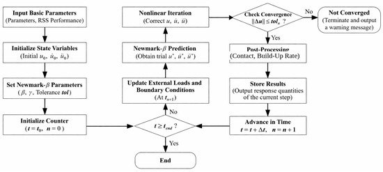
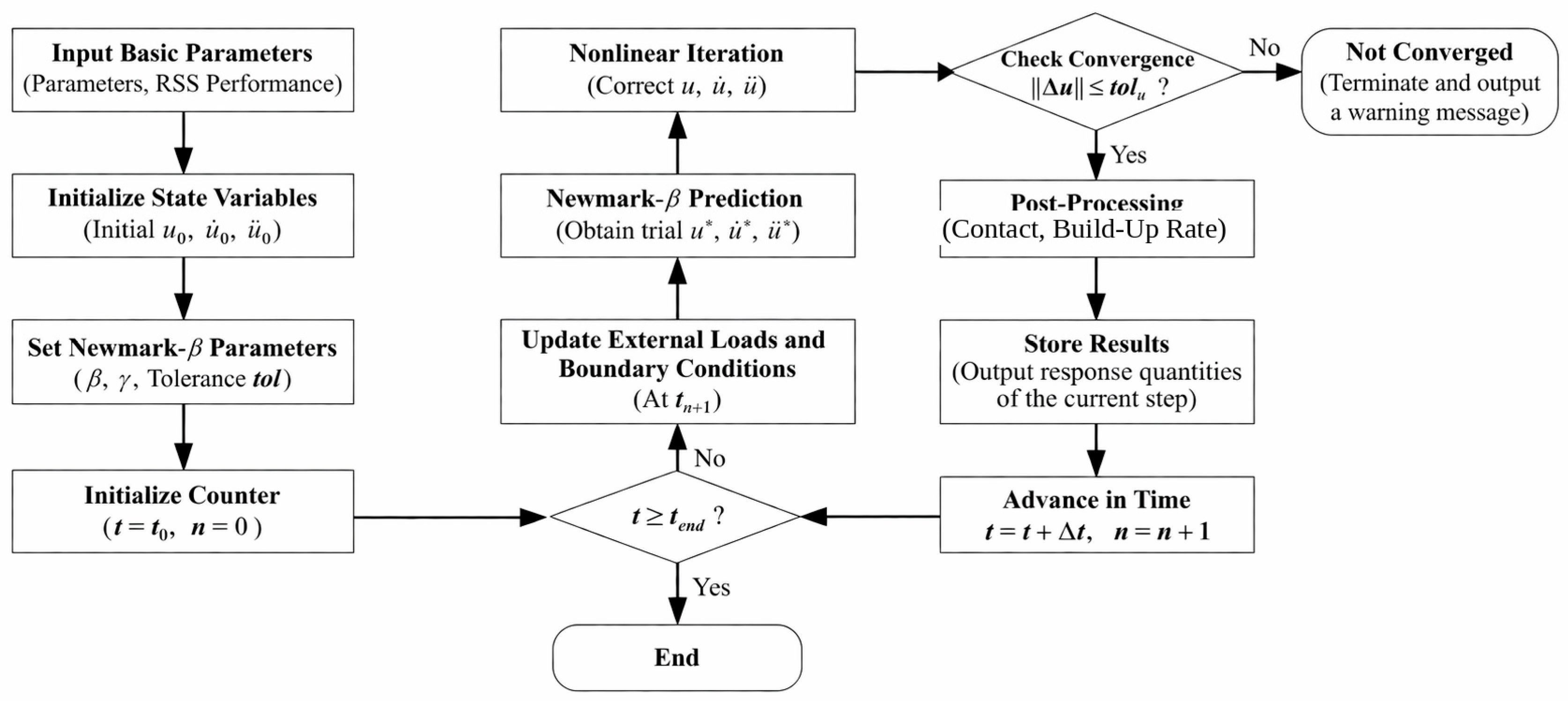
The dynamic response is solved using the Newmark–β-based implicit time integration method. Contact and constraint conditions are coupled into the nonlinear equilibrium equations within each time step via an incremental–iterative approach. The iteration process is controlled by a residual convergence criterion to ensure numerical stability and computational accuracy (see Figure 2).
Figure 2.
Calculation flowchart.
3. Model Verification
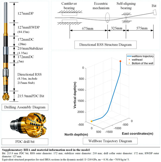
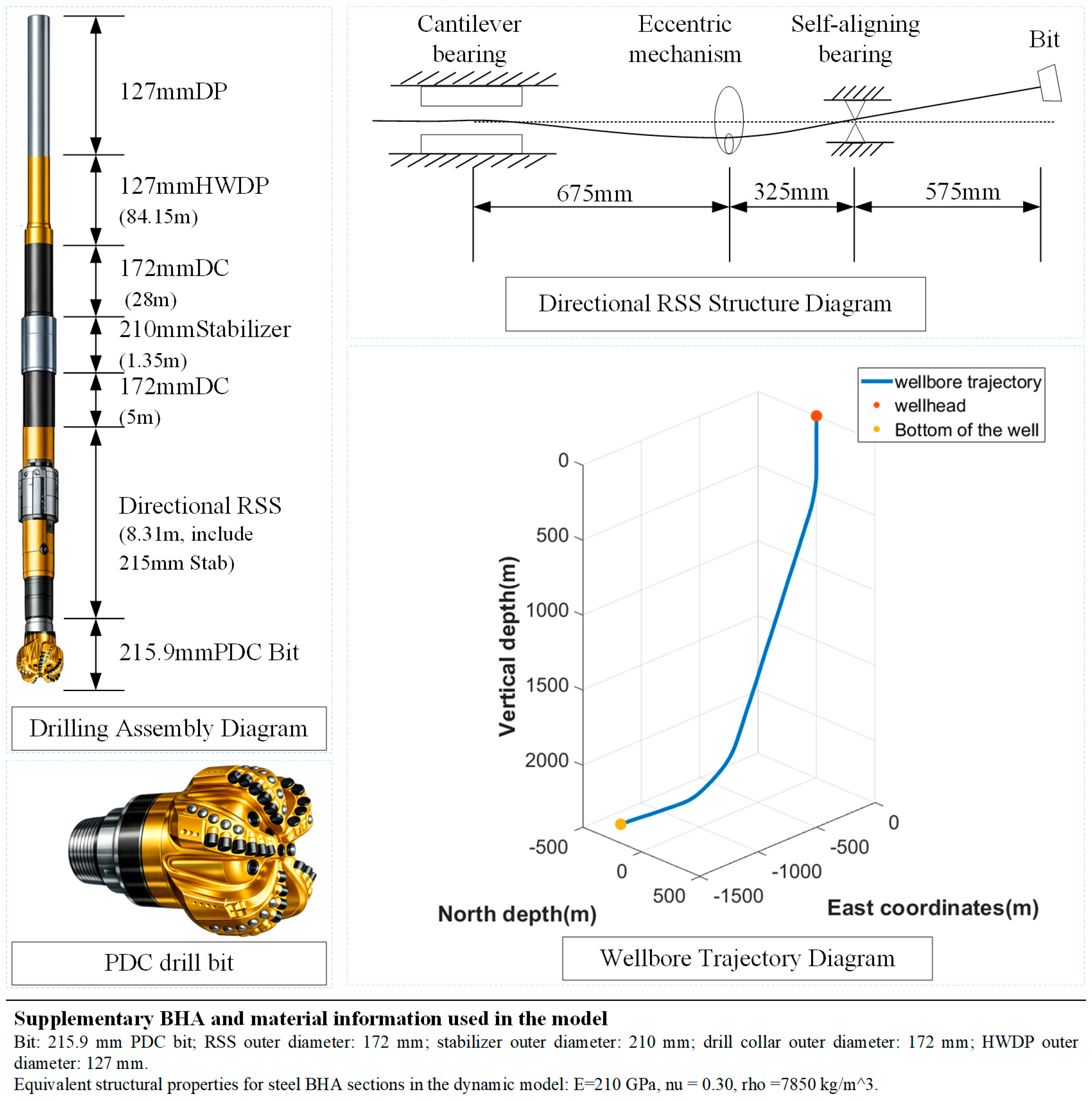
An exploratory well in the Bohai Sea, as illustrated in Figure 3, was selected for model validation. The wellbore diameter is 215.9 mm. The secondary build-up section begins at a depth of 2200 m within the Shahejie Formation. The WOB fluctuates between 48 kN and 77 kN, with an average of 62.7 kN, while the rotary speed is maintained at 70 r/min. The BHA used in this well consists of a 215.9 mm drill bit + 172 mm point-the-bit RSS (8.31 m, equipped with a 215 mm stabilizer) + 172 mm non-magnetic drill collar (5 m) + 210 mm stabilizer (1.35 m) + 172 mm drill collar (28 m) + 127 mm heavy-weight drill pipe (84.15 m) + 127 mm drill pipe. Additionally, the simulation parameters are set with a WOB of 62.7 kN and a rotary speed of 70 r/min. Due to the confidentiality of the RSS tool, the deflection angle and related control parameters cannot be listed in detail.
Figure 3.
Schematic diagram of calculation parameters.
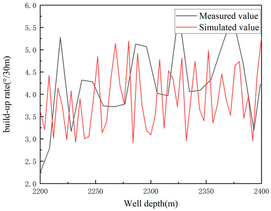
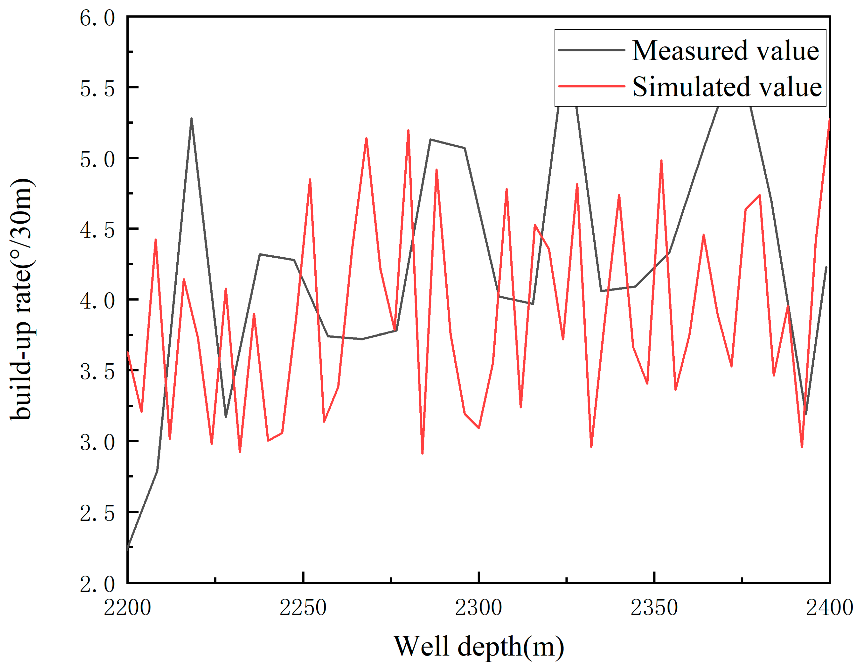
The results in Figure 4 demonstrate that the model reproduces the field-level BUR with acceptable engineering accuracy. Within the validated interval of 2200–2400 m, the predicted BUR ranges from 2.17 to 5.84 deg/30 m, with an average of 4.19 deg/30 m, whereas the measured BUR ranges from 2.91 to 5.28 deg/30 m, with an average of 3.80 deg/30 m. The corresponding average deviation is 0.39 deg/30 m, or about 10.3% relative to the measured mean. This level of agreement indicates that the model is reliable for ranking steering capacity and comparing parameter sensitivity within the validated operating window.
Figure 4.
Model verification.
Although the mean agreement is satisfactory, local discrepancies remain between the calculated and measured trends. The main reasons are that the field-recorded BUR is affected by local formation heterogeneity and operational disturbances, whereas the model uses averaged bit–rock parameters and equivalent boundary conditions; the verification simulation adopts representative constant inputs (WOB = 62.7 kN and rotary speed = 70 r/min), while the field process contains time-varying fluctuations in WOB, toolface control, and contact conditions; and the present contact formulation neglects some distributed borehole irregularities. Therefore, the model reproduces the average BUR level well, but slight mismatches in local trend and amplitude are still expected.
4. Analysis of Influencing Factors and Discussion
4.1. Impact of Deflection Angle
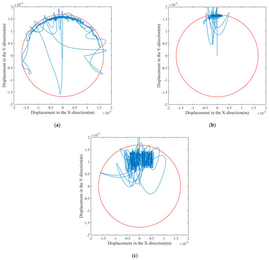
Figure 5 illustrates the lateral trajectories of the drill bit within the wellbore cross-section under varying deflection angles, where the blue curves represent the bit center’s planar trajectory over time, and the red circles denote the wellbore boundary. At a deflection angle of 0.5°, the trajectory exhibits a wide circumferential sweep near the wellbore wall, indicating extensive azimuthal coverage and frequent collisions with the wellbore under low deflection conditions. As the angle increases to 1°, the trajectory significantly converges, clustering within a localized region at the upper part of the borehole. The lateral displacement amplitude decreases, and the motion transitions to small-scale reciprocal oscillations. This suggests that the increased steering thrust and attitude constraints tend to stabilize the bit motion into a quasi-steady state, with contact occurring primarily at specific azimuths. Upon further increasing the angle to 1.5°, although the trajectory remains concentrated at the upper section, its dispersion increases compared to the 1° case, accompanied by several large-scale rebounding paths. This indicates that larger deflection angles introduce higher lateral loads, which exacerbate lateral vibrations and whirling tendencies, thereby reducing motion stability.
Figure 5.
Bit trajectories under different deflection angles: (a) deflection angles = 0.5°, (b) deflection angles = 1°, and (c) deflection angles = 1.5°.
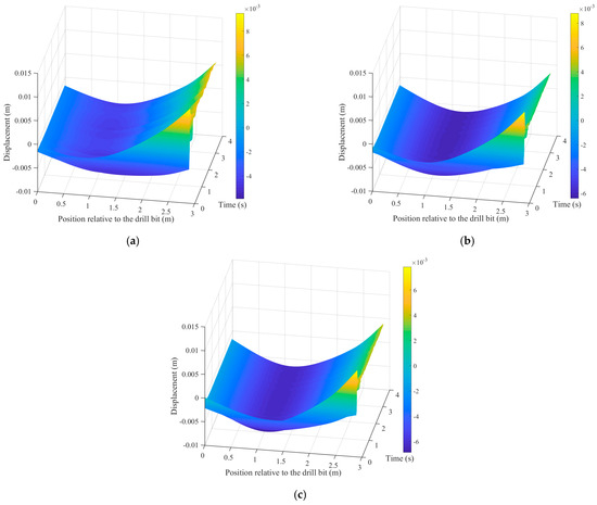
Figure 6 shows the schematic of the BHA lateral deformation under different deflection angles. The deformation distribution along the axial position exhibits a “concave” deflection characteristic across all three working conditions. As the deflection angle increases, this “concave” deformation of the BHA becomes more pronounced.
Figure 6.
BHA deflection for various deflection angles: (a) deflection angles = 0.5°, (b) deflection angles = 1°, and (c) deflection angles = 1.5°.
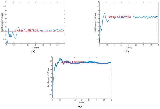
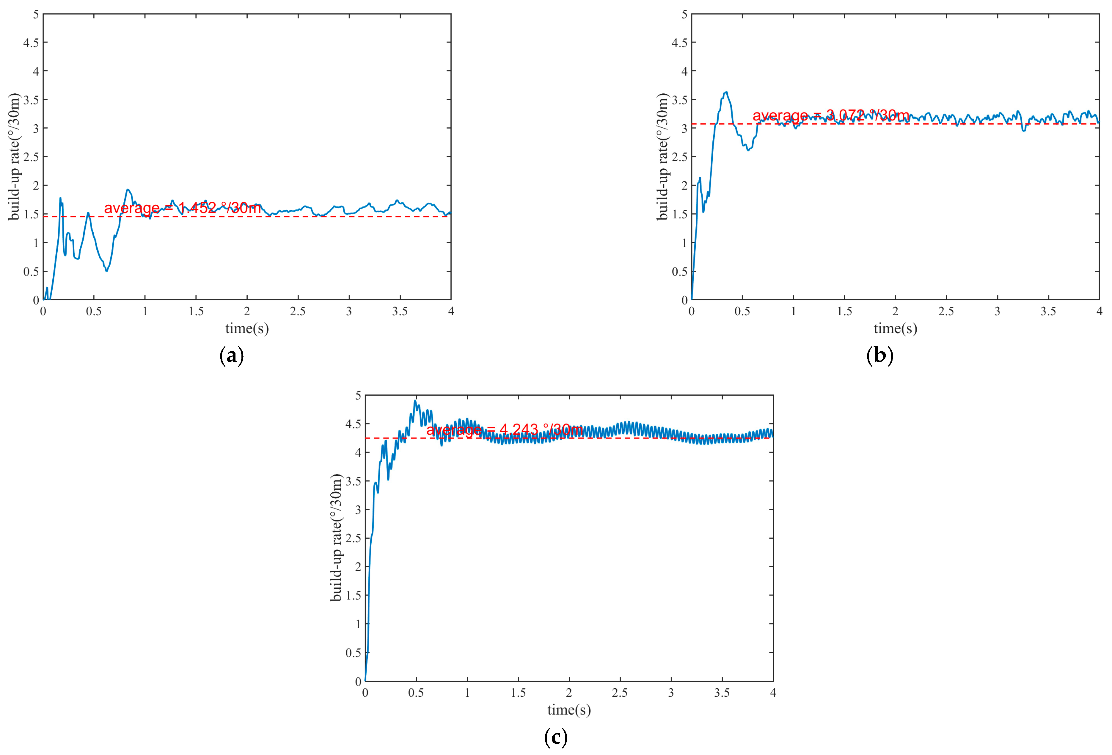
Figure 7 shows that the deflection angle is the dominant control variable for BUR because it directly prescribes the relative rotation at the equivalent steering joint. This imposed rotation increases bit inclination in the build-up plane, enlarges the lateral penetration components in the directional bit–rock law, and thereby generates a larger lateral side force and bending moment in the near-bit BHA. As a result, the average BUR increases from 1.452°/30 m at 0.5° to 4.251°/30 m at 1.5°, corresponding to a growth of about 192.8% across the tested range. The 1.0° case provides a useful intermediate state, where the BUR rises rapidly and the response stabilizes faster than in the 0.5° case, showing that moderate deflection improves both steering efficiency and output stability.
Figure 7.
BUR prediction diagram under different deflection angles: (a) deflection angles = 0.5°, (b) deflection angles = 1°, and (c) deflection angles = 1.5°.
However, the same mechanism that strengthens steering also amplifies dynamic disturbance when the imposed deflection becomes too large. At 1.5°, the stronger bit tilt increases lateral contact load, collision-rebound intensity, and local whirling tendency, which explains the visibly larger time-varying fluctuation of BUR after the initial transient. Therefore, the effect of deflection angle should be understood as a competition between steering-force enhancement and vibration/contact amplification: increasing deflection strongly raises the mean BUR, but excessive deflection reduces smoothness and may narrow the stable operating window.
The dominant role of the deflection angle can be understood from the fact that it directly controls the prescribed relative rotation at the equivalent steering joint, thereby increasing the bit tilt and the lateral penetration tendency in the build-up plane. As the deflection angle increases, the bit is forced to maintain a stronger directional bias, which leads to a substantial increase in the average BUR. However, the corresponding increase in trajectory dispersion and side-force fluctuation also indicates that excessive deflection amplifies near-bit contact and lateral vibration.
4.2. Impact of WOB
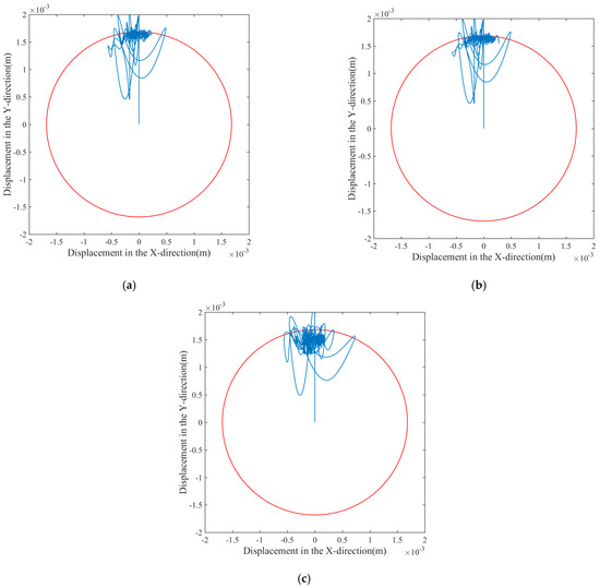
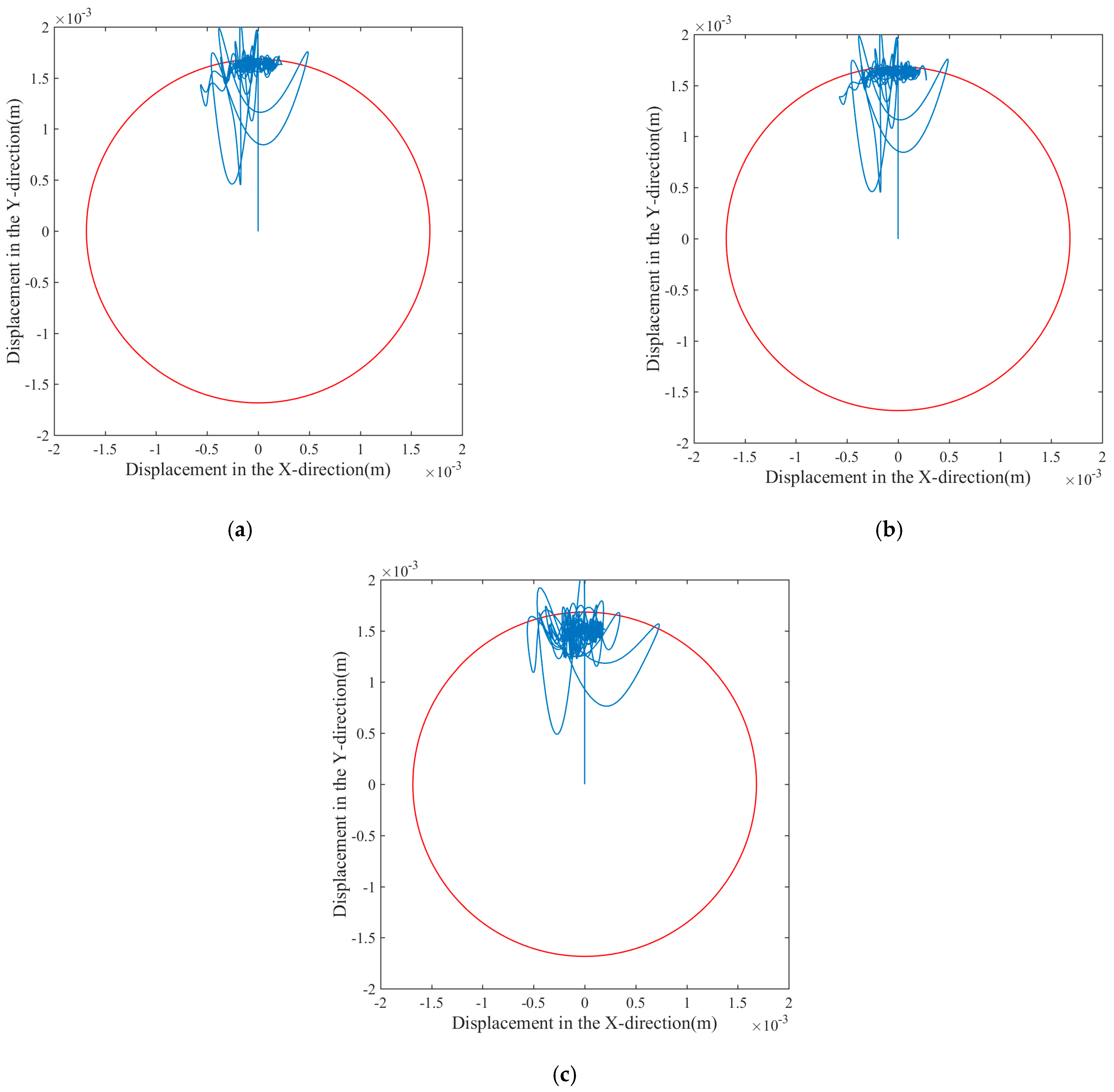
Under the three WOB conditions, the trajectories are primarily concentrated in a localized region at the upper part of the borehole, exhibiting significant azimuthal bias and trajectory clustering (Figure 8). This indicates that the drill bit maintains a stable contact azimuth under the influence of the steering force. Meanwhile, a few radial mutations are observed, reflecting the transient contact-impact states between the bit and the wellbore wall. As the WOB increases, the trajectory continues to revolve and swing mainly within the upper azimuth, with little change in overall morphology. However, the lateral dispersion of the trajectory and the number of orbital loops increase slightly with higher WOB, suggesting that a larger WOB enhances the lateral loading induced by bit–rock interaction.
Figure 8.
Bit trajectories under different WOB values: (a) WOB = 60 kN, (b) WOB = 80 kN, and (c) WOB = 100 kN.
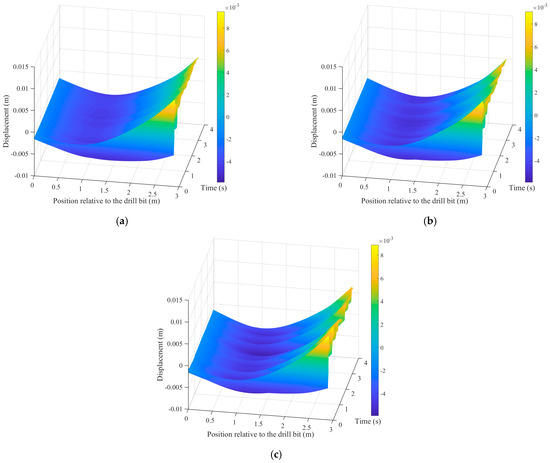
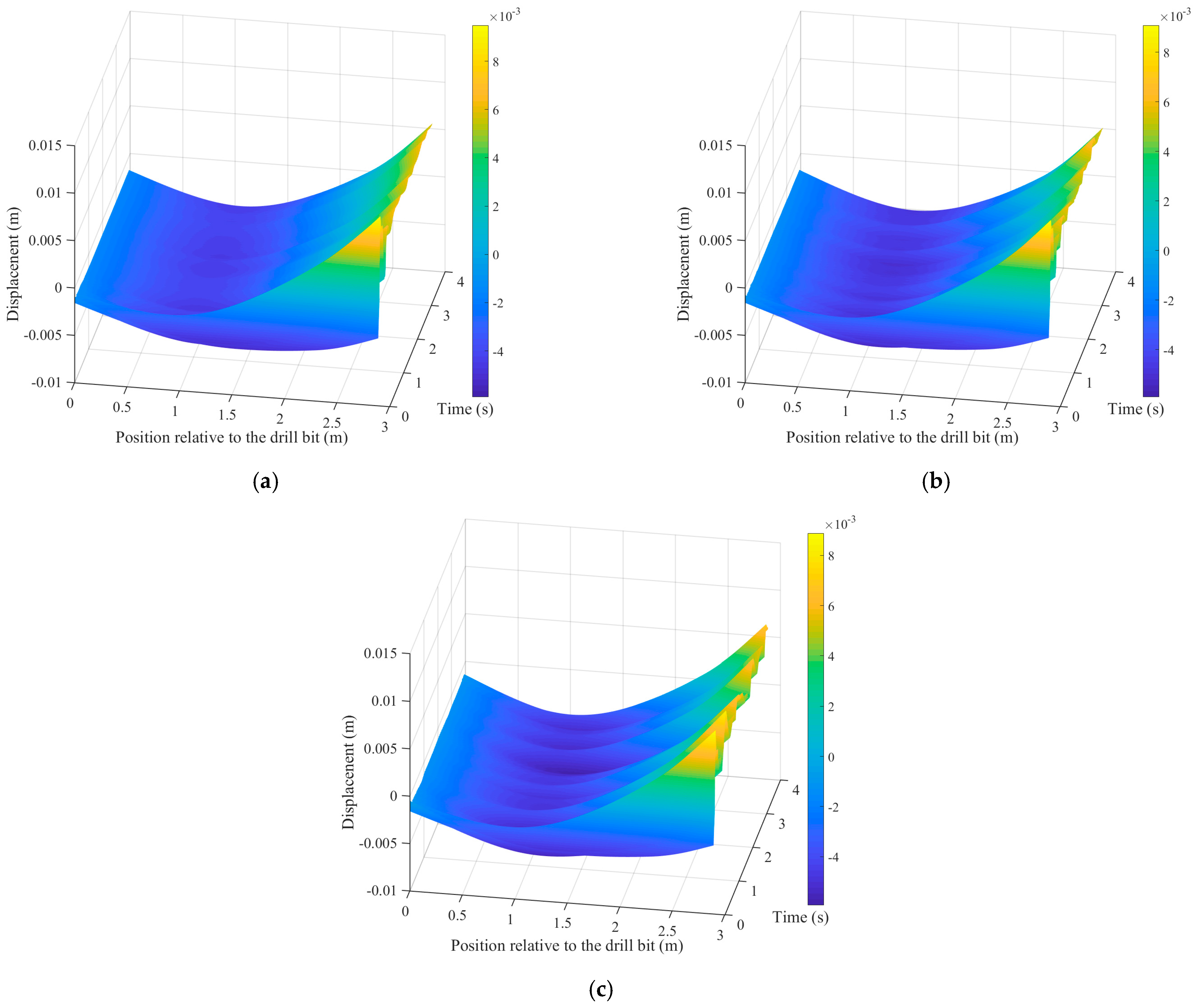
Figure 9 illustrates the BHA’s lateral deformation under varying WOB values. The overall deformation patterns remain consistent across different WOB levels, all exhibiting a characteristic “concave” shape. However, as the WOB increases, more pronounced stratified fluctuations become visible along the BHA. This indicates that an increase in WOB tends to reduce the toolface stability of the bottom hole assembly.
Figure 9.
BHA deflection under different WOB values: (a) WOB = 60 kN, (b) WOB = 80 kN, and (c) WOB = 100 kN.
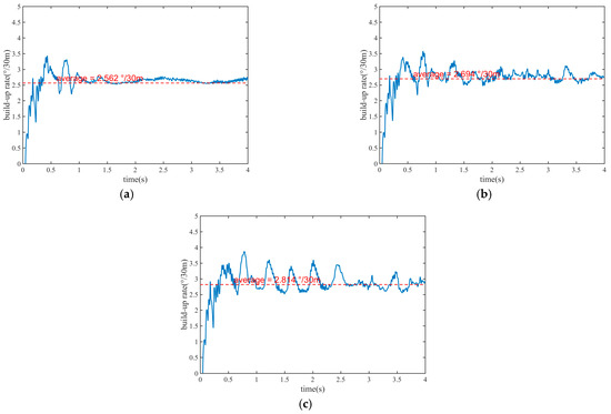
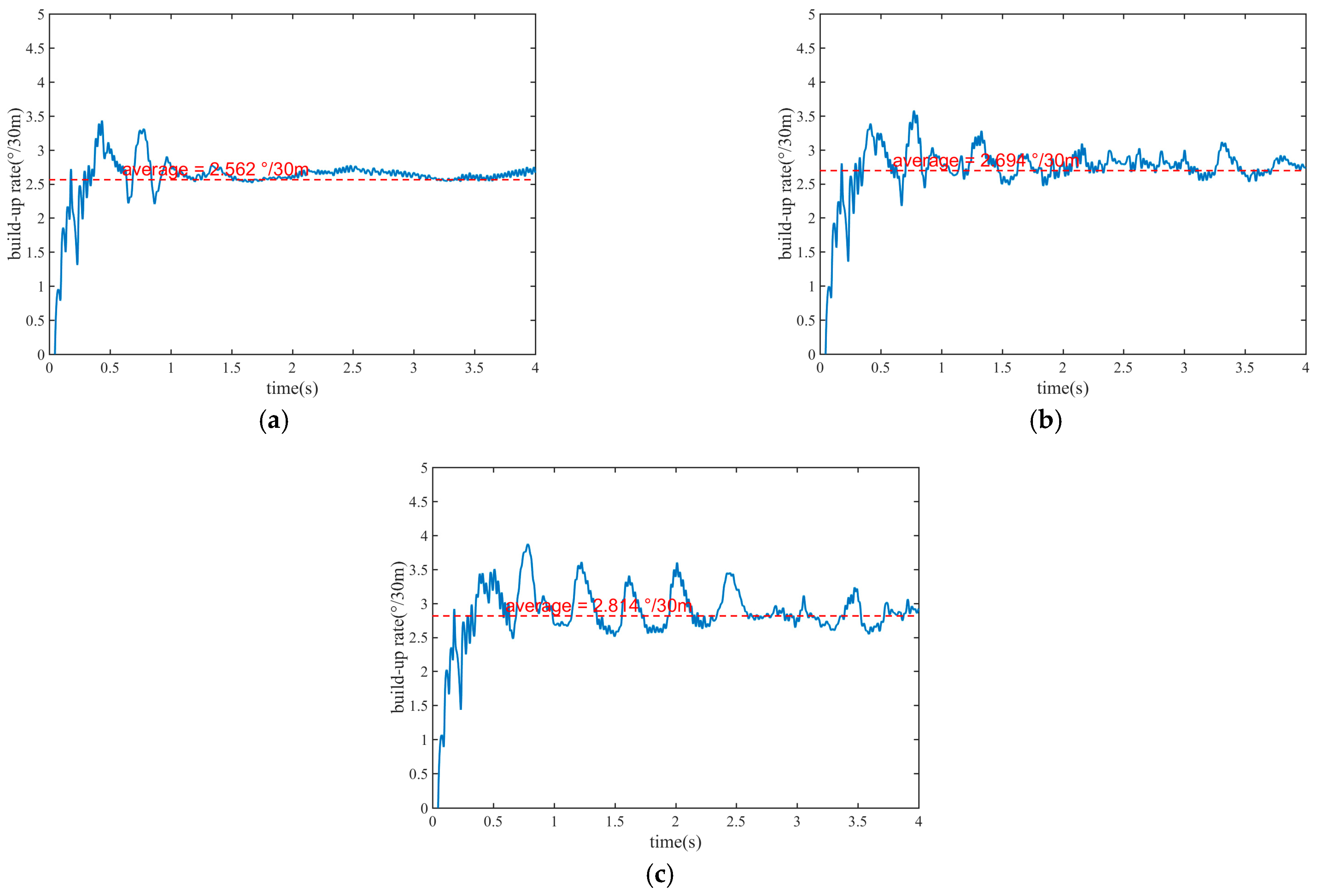
WOB influences BUR through an axial-to-lateral load-transfer pathway at the bit. A higher WOB increases the depth of cut per revolution and the cutting-related load components in the bit–rock interface law; under a deflected bit, part of this additional axial loading is converted into a larger lateral side force and near-bit bending moment, which enhances the steering output. This is why the average BUR rises from 2.281°/30 m at 60 kN to 2.814°/30 m at 100 kN, corresponding to an increase of about 23.4% across the tested range (Figure 10).
Figure 10.
Prediction BUR under different WOB values: (a) WOB = 60 kN, (b) WOB = 80 kN, and (c) WOB = 100 kN.
At the same time, a larger WOB also raises the normal contact force between the BHA and the wellbore wall, making the system more sensitive to local collision, rebound, and bending disturbance. Consequently, WOB has a weaker effect on the mean BUR than the deflection angle, but it still increases the fluctuation intensity of the response at high load. From an operational viewpoint, WOB should therefore be treated as an auxiliary tuning parameter that can enhance steering output within limits, rather than as the primary steering-control variable.
4.3. Impact of Rotary Speed
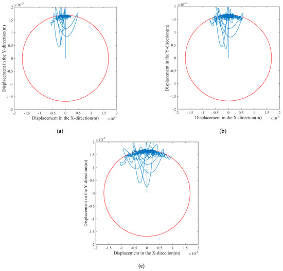
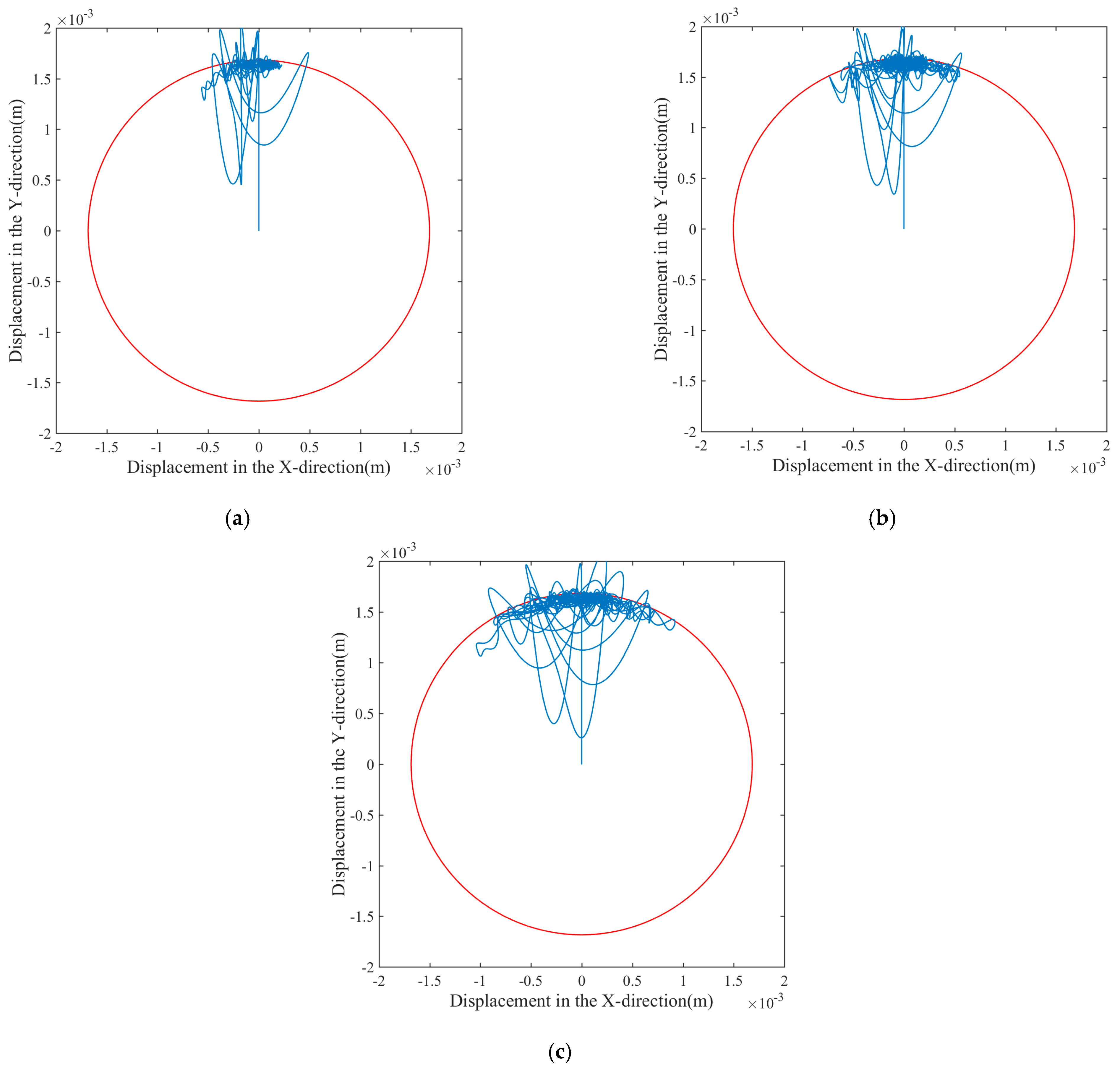
Under the three rotary speed conditions, the bit trajectories are primarily concentrated in a localized region at the upper part of the borehole, also exhibiting distinct azimuthal bias (Figure 11). The marginal impact of rotary speed on the contact orientation indicates that its influence on the bit’s lateral motion is primarily achieved by modulating the frequency and phase, rather than altering the steady-state bias.
Figure 11.
Bit trajectories under different rotary speeds: (a) rotary speed = 50 r/min, (b) rotary speed = 70 r/min, and (c) rotary speed = 90 r/min.
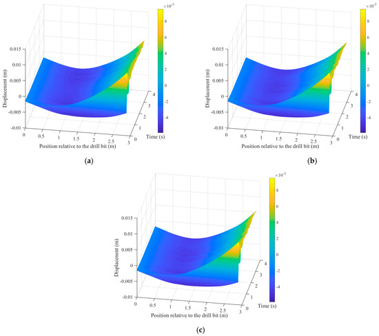
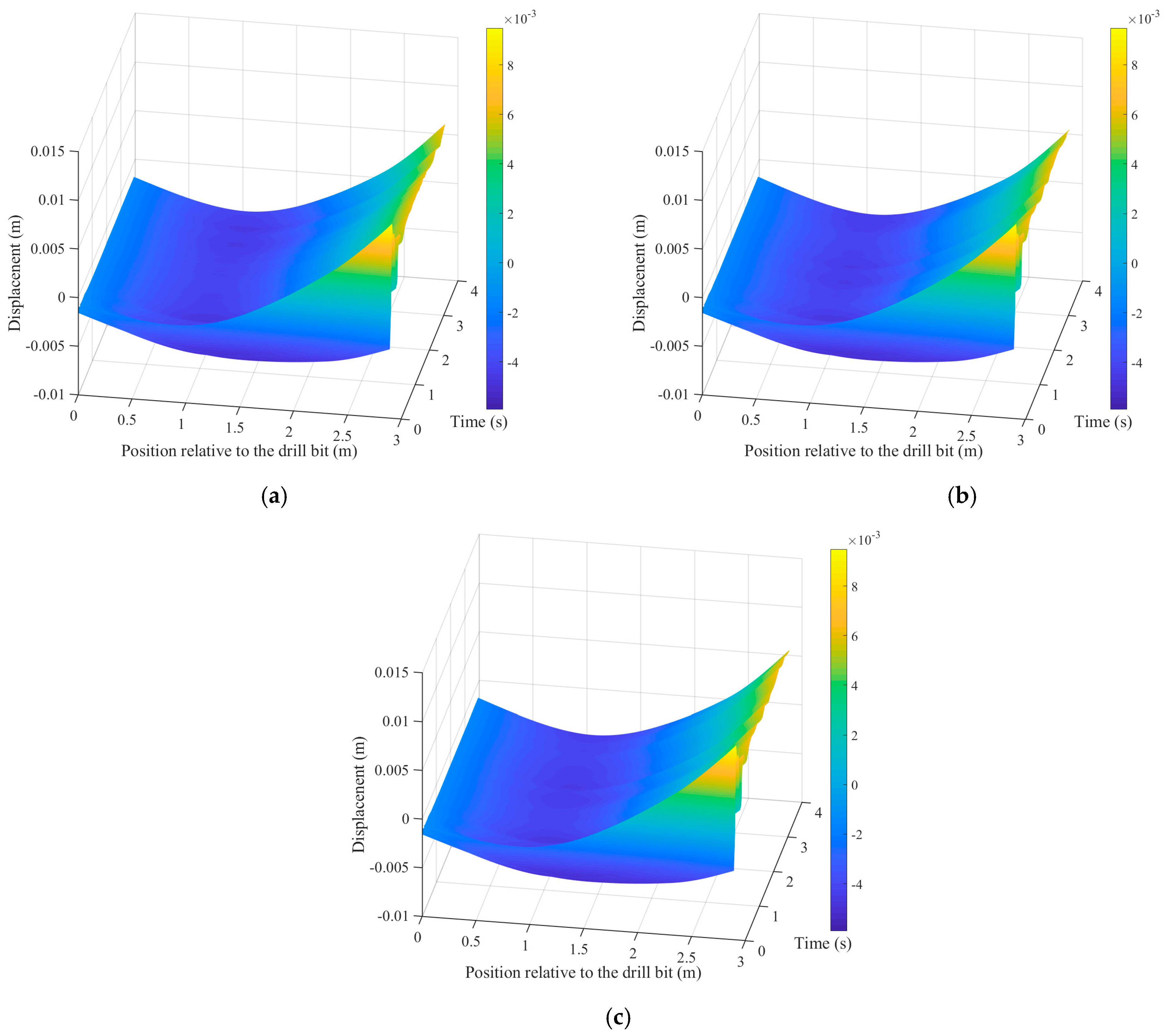
The overall morphology and peak magnitudes of the BHA remain largely consistent across the three rotary speeds (Figure 12). This indicates that within this speed range, rotary speed has a marginal impact on the average bending profile and quasi-steady deflection levels of the BHA. Its influence is primarily reflected in high-frequency vibrational details rather than in the global deflection behavior.
Figure 12.
BHA deflection under different rotary speeds: (a) rotary speed = 50 r/min, (b) rotary speed = 70 r/min, and (c) rotary speed = 90 r/min.
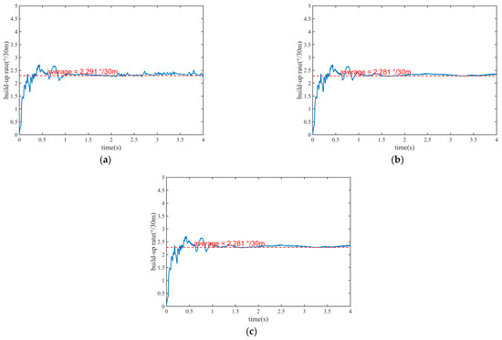
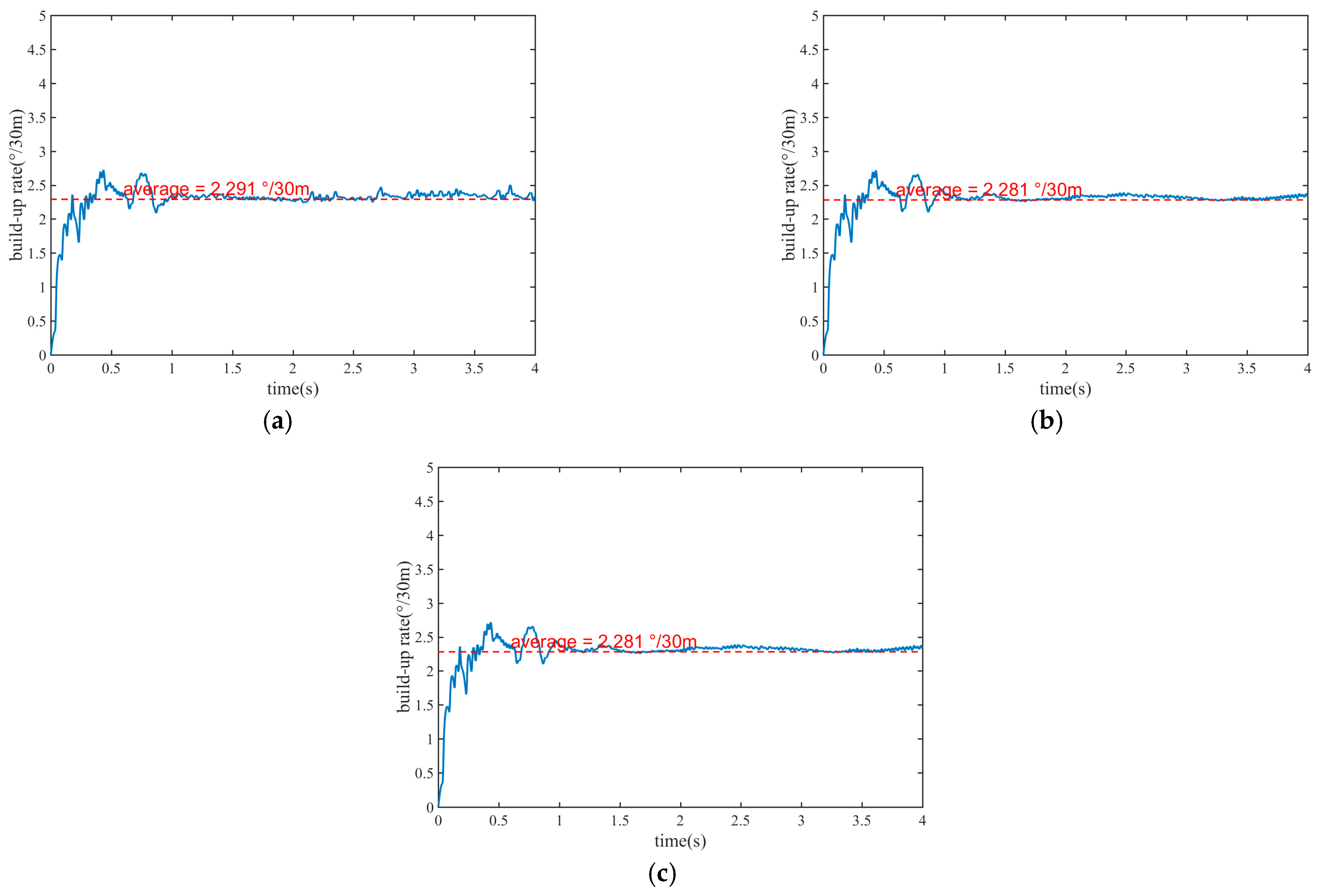
The average BURs under the three rotary speeds are remarkably similar: 2.291°/30 m at 50 r/min, 2.281°/30 m at 70 r/min, and 2.301°/30 m at 90 r/min. The maximum spread is only 0.020°/30 m, which is less than 1% of the mean level. These results indicate that within the range of 50–90 r/min, rotary speed has a negligible impact on the steady-state steering capacity under the current parameter combination and control strategy (Figure 13).
Figure 13.
Prediction BUR under different rotary speeds: (a) rotary speed = 50 r/min, (b) rotary speed = 70 r/min, and (c) rotary speed = 90 r/min.
In contrast, the rotary speed has only a limited influence on the mean BUR. This suggests that, under the current structural configuration and control mode, rotary speed mainly affects the excitation frequency, contact phase, and transient vibration details, rather than the quasi-steady steering bias itself. From an engineering perspective, rotary speed is more relevant to response smoothness and dynamic stability than to the average steering capability.
4.4. Discussion
Compared with conventional rigid or quasi-static BUR models [9,10], the present method provides a unified framework for simultaneously representing continuous BHA flexure, intermittent wellbore contact, and steering joint-induced bit inclination. This capability is important because previous BUR-oriented models mainly focus on steady geometric compatibility or simplified force balance, whereas dynamic drill string studies [19,20,21,22,30,31,32,33] emphasize vibration and contact response without explicitly describing the equivalent steering offset of a point-the-bit RSS. By embedding the hinge deflection-angle constraint into the finite element system, the current model links tool structure, steering action, and trajectory response within the same dynamic formulation.
This unified description enables the model to explain not only the mean BUR, but also the transient bit-trajectory clustering, localized BHA deformation, and time-dependent BUR fluctuations. From a practical viewpoint, the model can be used to evaluate steering capacity during BHA design, identify operating windows that balance steering efficiency and stability, and support parameter tuning for build-up sections in complex wells. In particular, the main advantage of the proposed 3D dynamic model is that it preserves the physical transfer chain from internal offset to bit attitude, BHA bending, wellbore contact, and finally BUR response, which is difficult to obtain from rigid or quasi-static formulations.
Despite the promising agreement with field data, the present model still has several limitations. First, the bit–rock interaction is represented by a reduced-order interface law rather than a cutter-resolved fracture model. Second, the wellbore contact model is simplified by penalty-based unilateral contact and friction, which may not fully capture distributed contact evolution under highly irregular borehole conditions. Third, the present validation relies on one representative field section. Therefore, broader calibration under extreme steering offsets, more severe borehole irregularity, and more complex operating conditions will be a necessary next step before extending the conclusions to a wider field envelope.
5. Conclusions
This study developed a 3D dynamic finite element model for the point-the-bit RSS, The primary findings are as follows:
- (1)
- The equivalent hinge deflection-angle constraint of the point-the-bit RSS is explicitly embedded into the overall structural dynamic equations and coupled with the nonlinear boundary conditions required for directional drilling, enabling internal steering action, BHA flexure, wellbore contact, and BUR response to be analyzed within a unified physical framework.
- (2)
- Sensitivity analysis reveals that the deflection angle is the dominant factor in steering capacity; increasing the angle from 0.5° to 1.5° enhances the average BUR from 1.452 to 4.251°/30 m. While increasing the WOB from 60 to 100 kN also improves the BUR (from 2.281 to 2.814°/30 m), the impact is secondary. Within the 50–90 r/min range, rotary speed has a marginal effect on the average BUR but significantly dictates transient fluctuations.
- (3)
- Although higher deflection angles and WOB improve steering efficiency, they aggravate localized bending and increase the risk of wellbore contact in the near-bit region. In engineering practice, steering targets should primarily be achieved through deflection-angle adjustments, supplemented by moderate WOB tuning.
Author Contributions
Conceptualization, Z.T. and Y.H.; methodology, Z.T.; software, J.H.; validation, Y.C., J.H., and Y.S.; formal analysis, Y.H.; investigation, Z.T.; resources, Y.H.; data curation, Z.T.; writing—original draft preparation, J.H.; writing—review and editing, Z.T.; visualization, Y.C.; supervision, Y.H.; project administration, Z.T. and Y.S.; funding acquisition, Z.T. and Y.H. All authors have read and agreed to the published version of the manuscript.
Funding
This research was funded by National Key R&D Program of China, grant number 2023YFC2810901.
Data Availability Statement
The original contributions presented in this study are included in the article. Further inquiries can be directed to the corresponding author.
Conflicts of Interest
Authors Zheng Tian, Yufa He, and Yu Chen were employed by the company CNOOC Research Institute Co., Ltd. The remaining authors declare that the research was conducted in the absence of any commercial or financial relationships that could be construed as potential conflicts of interest. The CNOOC Research Institute Co., Ltd., had no role in the design of the study; in the collection, analyses, or interpretation of data; in the writing of the manuscript; or in the decision to publish the results.
Abbreviations
The following abbreviations are used in this manuscript:
| RSS | Rotary steerable system |
| BUR | Build-up rate |
| BHA | Bottom hole assembly |
| WOB | Weight on bit |
References
- Andrade, C.P.S.; Saavedra, J.L.; Tunkiel, A.; Sui, D. Rotary Steerable Systems: Mathematical Modeling and Their Case Study. J. Pet. Explor. Prod. Technol. 2021, 11, 2743–2761. [Google Scholar] [CrossRef] [Scilit]
- Demirer, N.; Zalluhoglu, U.; Marck, J.; Darbe, R.; Morari, M. Autonomous Directional Drilling with Rotary Steerable Systems. In Proceedings of the 2019 American Control Conference (ACC); IEEE: New York, NY, USA, 2019; pp. 5203–5208. [Google Scholar] [CrossRef] [Scilit]
- Schaaf, S.; Mallary, C.R.; Pafitis, D. Point-the-Bit Rotary Steerable System: Theory and Field Results. In Proceedings of the SPE Annual Technical Conference and Exhibition, Dallas, TX, USA, 1–4 October 2000; SPE: Dallas, TX, USA, 2000; p. SPE-63247-MS. [Google Scholar] [CrossRef]
- Menand, S.; Simon, C.; Gaombalet, J.; Macresy, L.; Gerbaud, L.; Ben Hamida, M.; Amghar, Y.; Denoix, H.; Cuiller, B.; Sinardet, H. PDC Bit Steerability Modeling and Testing for Push-the-Bit and Point-the-Bit RSS. In Proceedings of the IADC/SPE Drilling Conference and Exhibition, San Diego, CA, USA, 6–8 March 2012; SPE: Dallas, TX, USA, 2012; p. SPE-151283-MS. [Google Scholar] [CrossRef] [Scilit]
- Li, R.; Georgy, J.; Zhao, J.; Noureldin, A. Testing a New Integrated Solution for MEMS Inertial Measurement Unit Used for Measurement-While-Drilling in Rotary Steerable System. Sens. Lett. 2012, 10, 719–725. [Google Scholar] [CrossRef] [Scilit]
- Kim, J.; Myung, H. Development of a Novel Hybrid-Type Rotary Steerable System for Directional Drilling. IEEE Access 2017, 5, 24678–24687. [Google Scholar] [CrossRef] [Scilit]
- Wang, J.; Xue, Q.; Li, L.; Huang, L.; Li, F.; Liu, B. Influence of Flex-Sub on Mechanical Properties of Rotary Steerable Drilling System. Mech. Sci. 2020, 11, 285–297. [Google Scholar] [CrossRef] [Scilit]
- Geng, H.; Zhang, B.; Xie, Y. Rotary Steerable Drilling Technology: Bottlenecks Breakthroughs and Intelligent Trends in China Shale Gas Development. Processes 2025, 13, 3471. [Google Scholar] [CrossRef] [Scilit]
- Ho, H.-S. SPE 16658. Prediction of drilling trajectory in directional wells via a new rock-bit interaction model: Ho, H S Proc 1987 SPE Annual Technical Conference, Drilling, Dallas, Sept 27–30 1987P83–95. Publ Richardson: SPE, 1987. Int. J. Rock Mech. Min. Sci. Geomech. Abstr. 1988, 25, 235. [Google Scholar] [CrossRef] [Scilit]
- Menand, S.; Sellami, H.; Simon, C.; Besson, A.; Silva, N.D. How the Bit Profile and Gages Affect the Well Trajectory. Presented at the IADC/SPE Drilling Conference, Dallas, TX, USA, 26–28 February 2002. [Google Scholar] [CrossRef]
- Huang, W.; Wang, G.; Gao, D. A Method for Predicting the Build-up Rate of ‘Push-the-Bit’ Rotary Steering System. Nat. Gas Ind. B 2021, 8, 622–627. [Google Scholar] [CrossRef] [Scilit]
- Chen, T.; Liu, G.; He, X.; Li, J.; Wang, W. Calculation Method of the Build-up Rate of the Internal Push Point-the-Bit Rotary Steering Tool. Geoenergy Sci. Eng. 2023, 230, 212177. [Google Scholar] [CrossRef] [Scilit]
- Zafarian, H.; Ameri, M.; Vaghasloo, Y.A.; Soleymanpour, J. Error Reduction of Tracking Planned Trajectory in a Thin Oil Layer Drilling Using Smart Rotary Steerable System. J. Pet. Sci. Eng. 2021, 196, 107668. [Google Scholar] [CrossRef] [Scilit]
- Li, S.; Wang, Y.; Wu, X.; Mao, Y.; Chen, J.; Yang, Y. Self-Stabilizing Control Strategy of Stabilized Platform for Rotary Steerable Drilling System Based on Adaptive Backstepping Control. Actuators 2024, 13, 116. [Google Scholar] [CrossRef] [Scilit]
- Xu, J.; Demirer, N.; Pho, V.; Tian, K.; Zhang, H.; Bhaidasna, K.; Darbe, R.; Chen, D. Real Time Multi-Inputs Multi-Outputs Economic Model Predictive Control for Directional Drilling Based on Fast Modeling and Sensor Fusion. J. Process Control 2025, 156, 103577. [Google Scholar] [CrossRef] [Scilit]
- Detournay, E.; Defourny, P. A Phenomenological Model for the Drilling Action of Drag Bits. Int. J. Rock Mech. Min. Sci. Geomech. Abstr. 1992, 29, 13–23. [Google Scholar] [CrossRef] [Scilit]
- Ghasemloonia, A.; Geoff Rideout, D.; Butt, S.D. A Review of Drillstring Vibration Modeling and Suppression Methods. J. Pet. Sci. Eng. 2015, 131, 150–164. [Google Scholar] [CrossRef] [Scilit]
- Tucker, W.R.; Wang, C. An Integrated Model for Drill-String Dynamics. J. Sound Vib. 1999, 224, 123–165. [Google Scholar] [CrossRef] [Scilit]
- Xiang, C.; Fang, P.; Li, H.; Feng, H.; Tang, B.; Zhang, T.; Xiao, G. Nonlinear Dynamics of a Drillstring System with PDC Bit in Curved Wells Based on the Finite Element Method. Geoenergy Sci. Eng. 2023, 230, 212240. [Google Scholar] [CrossRef] [Scilit]
- Hou, X.; Zhou, Y.; Meng, G.; Liu, X. Dynamic Stability and Optimization of a Delay-Affected Drill String with an Anti-Stall Tool. J. Sound Vib. 2025, 604, 118960. [Google Scholar] [CrossRef] [Scilit]
- Tian, J.; Wu, Y.; Xiao, G.; Dai, L. Lateral Vibration Characteristics Analysis and Vibration Mode Study of Drill String in Deep Horizontal Well. J. Comput. Nonlinear Dyn. 2025, 20, 111001. [Google Scholar] [CrossRef] [Scilit]
- Liu, W.; Ni, H.; Wang, Y.; Guo, Y.; Gao, Y.; He, P. Dynamic Modeling and Load Transfer Prediction of Drill-String Axial Vibration in Horizontal Well Drilling. Tribol. Int. 2023, 177, 107986. [Google Scholar] [CrossRef] [Scilit]
- Zhang, Y.; Ashok, P.; Chen, D.; Van Oort, E. Coupled Drillstring Dynamics Modeling Using 3D Field-Consistent Corotational Beam Elements. Geoenergy Sci. Eng. 2024, 233, 212424. [Google Scholar] [CrossRef] [Scilit]
- Wang, W.; Geng, Y.; Sun, J.; Xu, H.; Sheng, L. Sensor Fault Detection and Minimum Detectable Fault Analysis for Dynamic Point-the-Bit Rotary Steerable System. ISA Trans. 2022, 127, 108–119. [Google Scholar] [CrossRef] [Scilit]
- Zhang, Z.; Qi, Z.; Wu, Z.; Fang, H. A Spatial Euler-Bernoulli Beam Element for Rigid-Flexible Coupling Dynamic Analysis of Flexible Structures. Shock Vib. 2015, 2015, 208127. [Google Scholar] [CrossRef] [Scilit]
- Mao, L.; Ma, M.; Cai, M. Research on the Dynamics of Drillstring Considering Bit–Rock Nonlinear Interaction. Int. J. Non-Linear Mech. 2023, 148, 104301. [Google Scholar] [CrossRef] [Scilit]
- Motamedian, H.R.; Kulachenko, A. Rotational Constraint between Beams in 3-D Space. Mech. Sci. 2018, 9, 373–387. [Google Scholar] [CrossRef] [Scilit]
- Fang, P.; Ding, S.; Yang, K.; Li, G.; Xiao, D. Dynamics Characteristics of Axial–Torsional–Lateral Drill String System under Wellbore Constraints. Int. J. Non-Linear Mech. 2022, 146, 104176. [Google Scholar] [CrossRef] [Scilit]
- Perneder, L.; Detournay, E.; Downton, G. Bit/Rock Interface Laws in Directional Drilling. Int. J. Rock Mech. Min. Sci. 2012, 51, 81–90. [Google Scholar] [CrossRef] [Scilit]
- Zhang, H.; Tian, K.; Bhaidasna, K. Efficient Contact Algorithm for 3D Finite Element Modeling of Bottomhole Assemblies: Validation and Application. SPE J. 2025, 30, 1237–1255. [Google Scholar] [CrossRef] [Scilit]
- Tian, J.; Xie, Y.; Al-Mamoori, H.N.; Kana, A.D.; Dai, L. Dynamic Characteristics and Parameter Analysis of Drill String System with Sliding Drilling Controller. Int. J. Non-Linear Mech. 2025, 171, 105028. [Google Scholar] [CrossRef] [Scilit]
- Khulief, Y.A.; Al-Naser, H. Finite Element Dynamic Analysis of Drillstrings. Finite Elem. Anal. Des. 2005, 41, 1270–1288. [Google Scholar] [CrossRef] [Scilit]
- Liao, C.-M.; Vlajic, N.; Karki, H.; Balachandran, B. Parametric Studies on Drill-String Motions. Int. J. Mech. Sci. 2012, 54, 260–268. [Google Scholar] [CrossRef] [Scilit]
Disclaimer/Publisher’s Note: The statements, opinions and data contained in all publications are solely those of the individual author(s) and contributor(s) and not of MDPI and/or the editor(s). MDPI and/or the editor(s) disclaim responsibility for any injury to people or property resulting from any ideas, methods, instructions or products referred to in the content. |
© 2026 by the authors. Licensee MDPI, Basel, Switzerland. This article is an open access article distributed under the terms and conditions of the Creative Commons Attribution (CC BY) license.