


Abstract
To address the instability of small coal pillars in gob-side entry driving under thick and hard roof conditions, this study proposes a synergistic control technology combining “pressure relief, bundle control, and strong support”. First, a segmented deflection curve model of the coal pillar was established to quantify the correlation between pillar deformation and dominant controlling factors. Numerical simulations (FLAC3D) were then performed to optimize the roof cutting parameters, determining an optimal cutting height of 23.2 m and a cutting angle of 9°. Based on these findings, a comprehensive control scheme was implemented in the Fucun Coal Mine. Field monitoring results indicate that the proposed technology effectively controlled the lateral displacement of the coal pillar to 264 mm and maintained the stability of the roadway. This study provides a theoretical basis and practical reference for deformation control in similar geological conditions.
1. Introduction
In the continuous mining of coal resources, the smooth progress of mining succession and the stability of roadways are ongoing problems that must be solved for efficient mine production. The traditional method of roadway layout along the gob generally ensures the stability of the surrounding rock and continuity by providing wide coal pillars. However, this method not only consumes a large amount of coal resources and reduces the extraction rate but also significantly increases the likelihood of high stress concentration forming under deep mining conditions, inducing coal pillar instability and even dynamic disasters. In order to balance mining succession and resource recovery, the technique of implementing a narrow coal pillar roadway along the gob has been gradually applied in recent years. However, under the action of a thick, hard roof, high ground, stress, and multiple mining disturbances, narrow coal pillars exhibit a greater tendency to deform and become unstable, which has become a key problem restricting the stability of roadways along the gob. To address this challenge, it is necessary to conduct a systematic study on the corresponding instability mechanism and control techniques [1,2,3].
In recent years, numerous domestic scholars have conducted extensive research on the instability of roadways with small coal pillars. Huang Wanpeng et al. [4] conducted a systematic study on the layout of “double roadway excavation and narrow coal pillars” and the stability of the surrounding rock and proposed to reduce stress concentration and suppress damage propagation by optimizing the roadway–coal pillar combination and construction sequence. Zhang Guanghui et al. [5] demonstrated in engineering practice that “deep and shallow hole combined blasting for pressure relief” can effectively weaken the concentrated load on the roof and improve the stress state of small coal pillars, providing conditions for roadway retention along the gob. Wang Wenjie [6] developed an analysis framework and control mechanisms for the stress evolution characteristics of roadways on the gob side, providing a basis for identifying high-risk sections of small coal pillars. Fan Hongguang et al. [7] further demonstrated the coupling law between the development of surrounding rock damage and support response under mining disturbance by studying the deformation mechanism and control techniques of the advanced roadway of the fully mechanized mining face from the perspective of roadway–working face coordination. Wang Mingshan [8] used a complete set of technical routes for roadway excavation along the gob of small coal pillars in medium and thick coal seams in the direction of “decompression-reinforcement” coordination and improved the overall stability by configuring differentiated parameters. For roadways with hard roofs, Du Yunjie [9] explored pre-pressure relief methods such as high-pressure hydraulic roof cutting to reduce the peak load caused by the key layer effect. In addition, Zhu Zhen [10] conducted an in-depth discussion on the surrounding rock structure mechanism of roof cutting and pillarless mining, providing theoretical support for understanding the stress and movement of overlying blocks after roof cutting. Zhang Wenzhang [11] focused on the key parameters and applications of roof cutting and roadway retention, and related research provided a selection of parameters and key points for field implementation, laying the foundation for engineering promotion. Recent studies have also investigated the failure depth of large mining height working surfaces and the energy evolution mechanism of coal failure [12,13].
Although previous studies have investigated coal pillar stability and roof cutting techniques, a critical research gap remains: there is a lack of quantitative expression correlating small coal pillar deformation with its dominant controlling factors under thick, hard roof conditions. Furthermore, most existing studies focus on a single control measure, failing to integrate pressure relief with active pillar reinforcement. To address these limitations, this paper focuses on the instability mechanism of gob-side small coal pillars in the Fucun Coal Mine. By establishing a mechanical deflection model and conducting numerical comparisons, we propose a synergistic “pressure relief–bundle control–strong support” technology. This study aims to provide a quantitative design basis for controlling pillar deformation and ensuring long-term roadway stability.
2. Project Overview
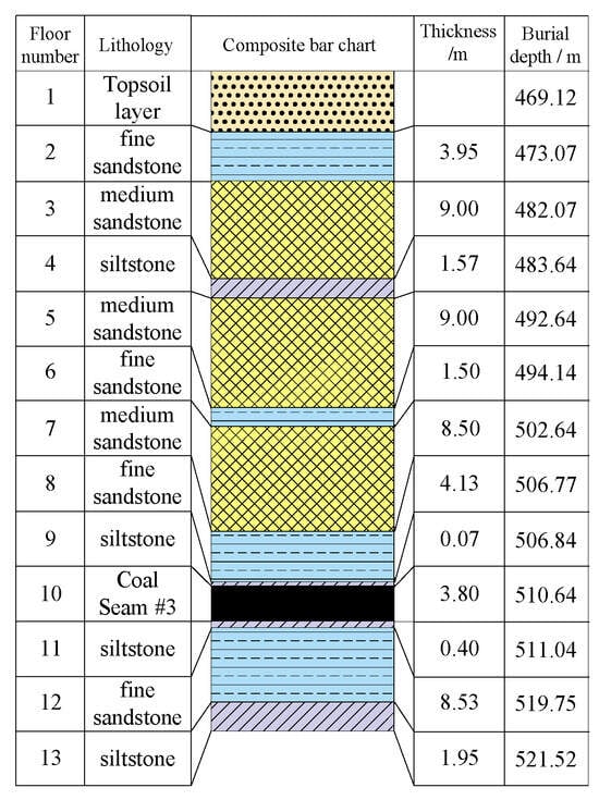
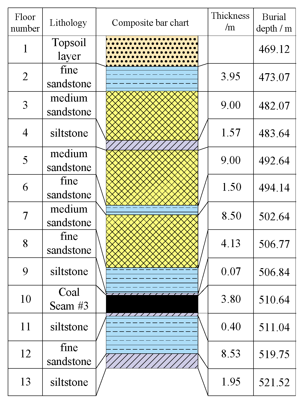
The 123-06 working face of Fucun Coal Mine Co., Ltd. (Jining, China) is located in the northern part of the East Twelfth Mining Area, primarily mining the Permian Shanxi Formation No. 3 coal seam, with an average burial depth of 510 m. The surface elevation is +33.1~+35.9 m. The coal seam structure is simple, with a strike of 100° and a dip of 190°. The f = 1.5~2.2, classifying it as medium-hard coal. Based on the exposure of adjacent mined working faces and tunnels, the coal seam thickness is 3.8 m, relatively stable, and possesses good mineability. Large-scale geological structures have not affected the coal seam structure. The roof strata of the working face are mainly composed of fine sandstone and medium sandstone, as shown in Figure 1.
Figure 1.
Columnar diagram of rock strata. (The symbol “#” denotes “Number”).
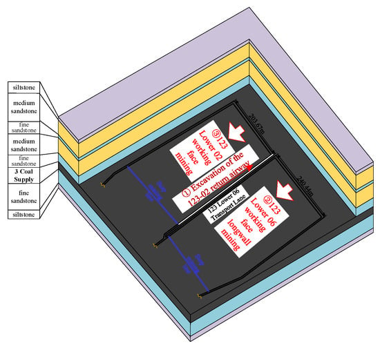
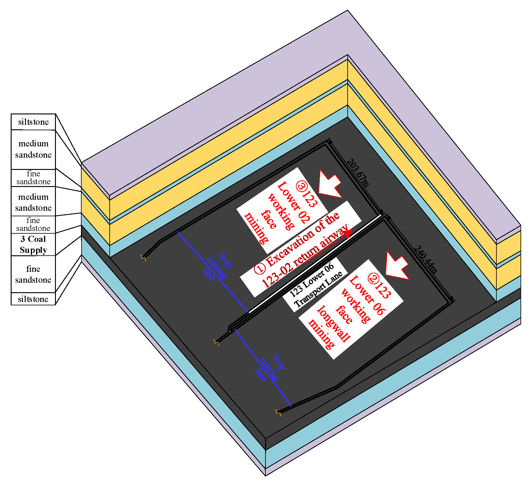
The haulage roadway of the 123-06 working face is adjacent to the 123-02 working face, as shown in Figure 2. Based on the production succession plan of Fucun Coal Mine, the 123-02 track roadway is no longer suitable for goaf excavation. In more detail, before the 123-06 working face is mined, the excavation and support work of the 123-02 track roadway must be completed. It is vital for the 123-02 track roadway and the 123-06 haulage roadway to be arranged as a double-roadway excavation with reserved small coal pillars; such an arrangement will enable the goaf roadway to be located in a relatively low-stress area. However, compared with wide coal pillar roadway protection, small coal pillars experience more significant disturbance under dual-face mining, resulting in relatively poor stability and a higher risk of large deformation in the reused roadway. Under deep, high-stress conditions, dynamic disasters may also occur.
Figure 2.
Working face roadway layout diagram.
In order to ensure the stability of the surrounding rock of the 123-02 track roadway under the condition of a thick and hard roof, it is therefore necessary to perform systematic research on the stability of small coal pillars, determine their instability mechanism, and develop effective control techniques to improve the stress state of the coal pillars in the section. Concurrently, it is necessary to propose a strengthening support technology scheme for the small coal pillars in the section to reduce the risk of large deformation and dynamic disasters in the roadway.
3. Analysis of the Instability Mechanism of Small Coal Pillars
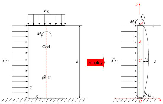
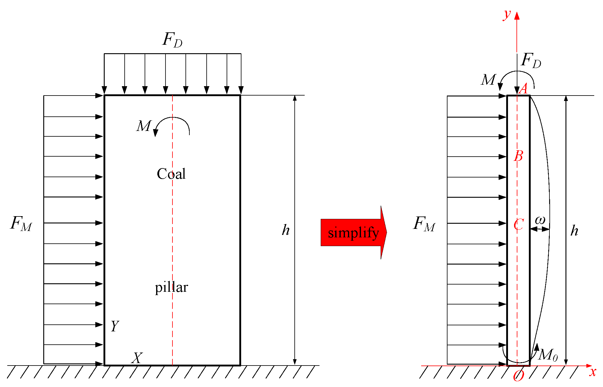
To derive the analytical solution for the mechanical deflection model, the coal pillar is simplified as a continuous, homogeneous, and isotropic elastic medium, neglecting random fissures. The roof–pillar interaction is treated as a load boundary condition with a rigid floor foundation, and the deformation is analyzed as a plane strain problem given the roadway geometry. These assumptions capture the primary mechanical behavior and facilitate the theoretical derivation. Based on the distribution characteristics of coal pillar support pressure and the stress characteristics of different regions, a stability model of the working face coal pillar is established. The working face coal pillar is simplified as possessing an elastic support at the top and a fixed support at the bottom, and is simultaneously subjected to the pressure FD of the overlying strata and the support force FM. The pressure difference formed by the support pressure of the unit body is regarded as the equivalent bending moment M. For ease of calculation, the fixed support condition at the bottom O point of the coal pillar is treated as a hinged support in the modeling process, and the constraint moment M0 is used to characterize the rotation restriction effect of the original fixed end on the section O. The mechanical model of coal pillar stability per unit width of the working face is obtained, as shown in Figure 3.
Figure 3.
Coal pillar stability model of the working face.
Let and , with O as the origin; the approximate differential equations of the deflection curves in segments OC, CB, and BA can be obtained from the bending moment theory, as shown in Equations (1)–(3).
OC segment (0 ≤ y ≤ h − b):
CB segment (h − a ≤ y ≤ h − b):
BA stage (h − a ≤ y ≤ h):
where M is the equivalent bending moment, kN·m; FD and FM are the overlying strata pressure and support force, respectively, kN; h is the section height, m; qD = FD/h and qM = FM/h represent the equivalent distributed loads, kN/m.
Combining the deflection differential equation and the elastic support term , we can obtain the approximate differential equations of the deflection curves within segments OC, CB, and BA as follows:
OC segment (0 ≤ y ≤ h − b):
CB segment (h − a ≤ y ≤ h − b):
BA stage (h − a ≤ y ≤ h):
In the formula, ω1, ω2, and ω3 represent the deflections of coal pillar segments OC, CB, and BA, respectively; h is the working face height; a and b are the distances from points B and C to the roof, i.e., AB = a and AC = b; E is the elastic modulus of the coal pillar; and I is the moment of inertia.
The boundary conditions and continuity conditions for the coal pillar mechanical model are as follows:
The equations for the deflection curves of the coal pillar segments OC, CB, and BA are as follows:
OC segment (ω1):
CB segment (ω2):
BA segment (ω3):
in:
In the formula, C1, C2, C3, C4, C5, and C6 are integration constants; when the maximum deflection of the coal column exceeds δcr, the coal column is considered to have entered an unstable state.
By establishing a three-segment deflection curve model for a small coal pillar and combining it with analytical solutions based on boundary and continuity conditions, the full-segment deflection curve can be obtained. The results show that the deformation of the coal pillar is mainly affected by key factors such as the overlying equivalent bending moment, support strength, coal body stiffness, and geometric segmentation parameters. Based on the above, it is necessary to further analyze the influencing factors to clarify the response mechanism of different parameter changes to the stability of the coal pillar [14,15,16,17].
4. Analysis of Influencing Factors
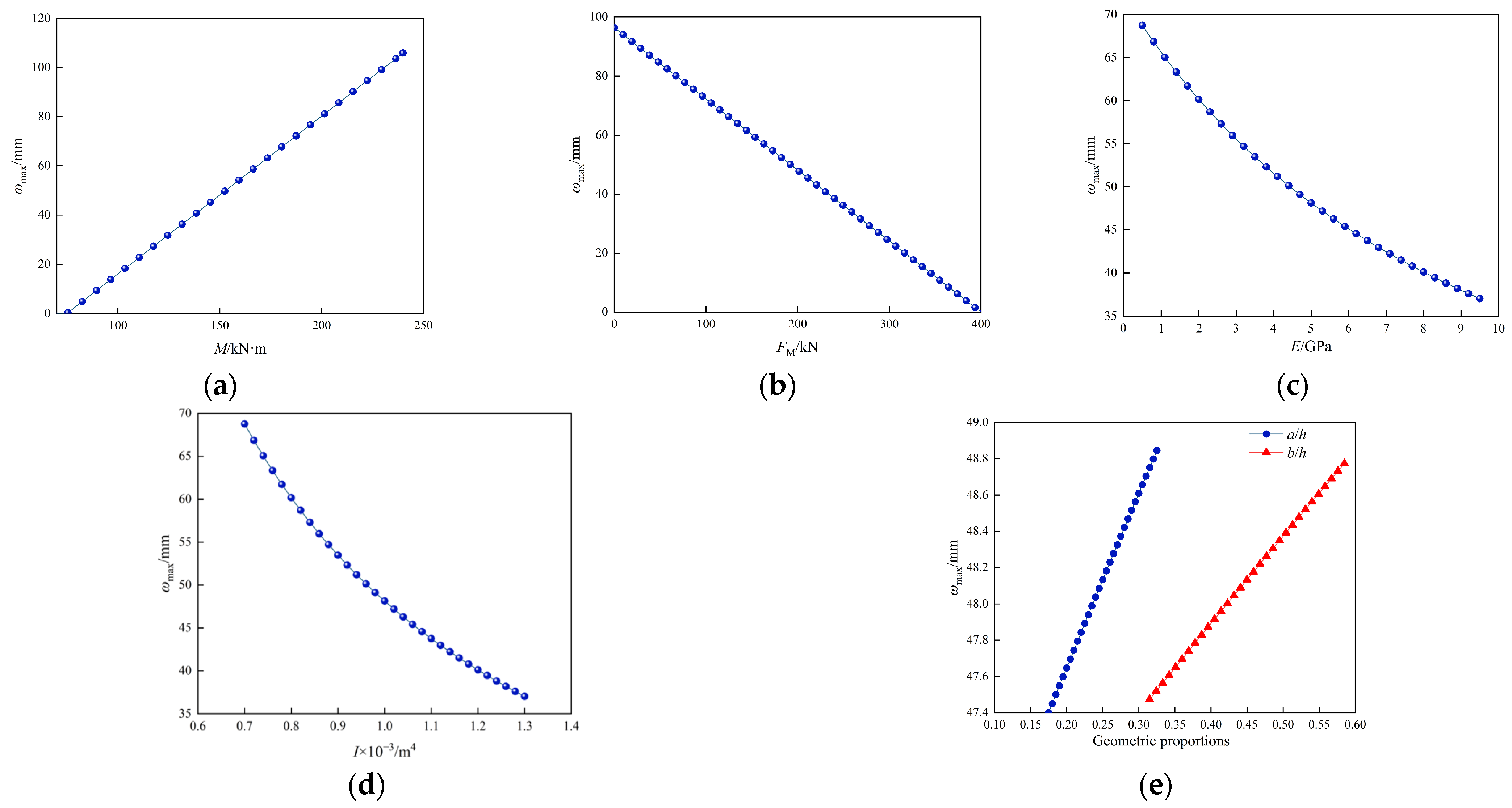
Based on the piecewise deflection curve model and boundary/continuity conditions detailed in Chapter 3, the single-factor method is used herein to examine and analyze the influence of each factor on the maximum deflection of the coal pillar. Based on Equations (13)–(17), MATLAB (version R2024b) is used to calculate and plot the influence of each factor on the maximum deflection of the coal pillar, as shown in Figure 4. The variables and units are consistent: E (GPa), h (m), M (kN·m), FM (kN), and I (m4).
Figure 4.
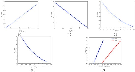
Influence of various factors on the maximum deflection of the coal pillar. (a) Effect of equivalent bending moment on deflection; (b) Impact of active support on deflection; (c) Effect of elastic modulus on deflection; (d) Influence of moment of inertia on deflection; (e) Effect of geometric segmentation on deflection.
- (1)
- Influence of Overburden Pressure on Deflection
As shown in Figure 4a, the maximum deflection increases approximately linearly with the increase in the equivalent overburden bending moment M. From the data presented in the figure, as M increases from 70.0 to 240.0 kN·m, the maximum deflection increases linearly from 0.0 to 105.9 mm. This finding indicates that when the span is large or the overhang is lengthened, the coal pillar is more prone to bending and bulging into the roadway.
- (2)
- Influence of Support Strength on Deflection
As shown in Figure 4b, the maximum deflection decreases significantly after increasing the active support force FM. From the data presented in the figure, as the active support force FM increases from 0.0 to 400.0 kN, the maximum deflection decreases from 96.3 mm to 0.0 mm. On-site, the preload and spacing should be applied according to the design, and reinforcement and densification should be performed in the deformation zone to reduce the deflection to a controllable range.
- (3)
- Influence of Elastic Modulus on Deflection
As shown in Figure 4c, an increase in the elastic modulus E of the coal pillar will simultaneously reduce the maximum deflection and shift the overall curve downward. Based on the data presented in the figure, as the elastic modulus E increases from 21.0 to 39.0 GPa, the maximum deflection decreases from 68.8 mm to 37.0 mm, a decrease of approximately 46.2%.
- (4)
- Influence of Moment of Inertia on Deflection
As shown in Figure 4d, increasing the equivalent moment of inertia I is also effective in suppressing deflection. Based on the data presented in the figure, as the moment of inertia I increases from 0.7 × 10⁻³ to 1.3 × 10⁻³ m4, the maximum deflection decreases from 68.8 mm to 37.0 mm, a decrease of approximately 46.2%. Adding support plates and connectors to key stress-bearing areas can improve bending stiffness.
- (5)
- Influence of Height and Geometric Segmentation
As shown in Figure 4e, geometric segmentation mainly affects subtle changes in the deflection amplitude and the peak distribution. Based on the data presented in the figure, when a/h increases from 0.175 to 0.325, the maximum deflection increases from 47.4 to 48.8 mm, an increase of approximately 3.0%; when b/h increases from 0.315 to 0.585, the maximum deflection increases from 47.5 to 48.8 mm, an increase of approximately 2.7%.
Based on the results presented in Figure 4, the effects can be classified into two categories: reducing the bending moment and increasing the support force. Reducing the bending moment is primarily achieved by adjusting the roof cutting and pressure relief parameters (angle, cutting height, and hole spacing/row spacing); when the parameters are appropriate, the equivalent bending moment M decreases faster, the overhang is shorter, and the maximum deflection is reduced [18]. Increasing support strength requires strengthening the lateral constraints (pre-tightening force, inter-row spacing, etc.), increasing FM, and reducing deflection [19]. In thick hard roofs or inclined coal seams, the optimization of roof cutting parameters can significantly weaken the peak stress and shorten the critical layer fracture step distance [20,21,22].
5. Small Coal Pillar Stability Control Technology
5.1. “Pressure Relief-Bundle Control-Strong Support” Stability Control Method
5.1.1. Determining Reasonable Parameters for Top Pressure Relief (Pressure Relief)
Within the framework of the overburden composite structure mechanics, the key layer control mechanism was introduced to classify and divide the structural characteristics of the overburden above the No. 3 coal seam, thus forming a targeted stratification scheme. Equations (19) and (20) show that the thickness of the direct roof of the No. 3 coal seam is 14.2 m, and the above is the basic roof of the coal seam.
In the formula, hz is the immediate roof height, m; hi is the thickness of the i-th stratum, m; KAi is the coefficient of fragmentation of the i-th stratum, generally taken as 1.2~1.3, and 1.3 is selected; and M is the coal seam thickness, taken as 3.8 m.
where qn(x) represents the load generated by the m-th rock layer above the coal seam on the n-th rock layer, and hi, γi, and Ei represent the thickness, density, and elastic modulus of the i-th rock layer, respectively (i ranges from n to m). When (22) is satisfied, the m + 1-th rock layer is the key layer.
The results are presented in Table 1. Two key layers are present in the overlying strata, located within the basic roof, at distances of 12.7 m and 23.2 m from the coal seam, respectively; the loads they bear are 0.262 MPa and 0.27 MPa, respectively; and the fracture steps are 20.50 m and 19.66 m, respectively.
Table 1.
Distribution table of key layers in overburden.
Within the area affected by cutting, there are n rock layers, numbered sequentially from bottom to top as 1, 2, 3,…, n. Then:
The above can be represented as:
Considering the overlying rock layers’ rotation, subsidence, and natural collapse:
In the formula: Hn is the thickness of the n-th rock layer (m); M is the mining height (3.8 m); kn is the bulking factor of the n-th rock layer; hq is the theoretical roof cutting height (m); and kp is the weighted average bulking factor of the caved zone (taken as 1.2).
Substituting the data, we obtain:
Based on the masonry beam theory and the S-R structural stability criterion, when the fracture surface of the main roof forms an angle with the vertical direction, the slippage instability of the rock block must satisfy the following equation:
That is:
In the formula, T is the horizontal thrust on the rock block, kN; R is the shear stress on the rock block, kN; q is the load intensity of the basic top, kN/m; L is the length of the basic top rock block, m; h is the thickness of the basic top, m; Δs is the subsidence of rock block B, m; φ is the friction angle between the rock masses, °; and θ is the cutting angle, °.
Substituting = 48°, L = 19.66 m, = 2.55 m, and h = 21.07 m into Equation (27), we obtain:
In summary, for a cut-off height greater than 23.2 m, drilling and blasting should be performed above the coal pillar at an angle of 9°. The drilling location should be as close as possible to the side of the coal pillar to minimize the overhang length.
5.1.2. Determination of Key Parameters for Through-Anchor Cables (Bundle Control)
After completing on-site sampling, indoor testing was conducted on the coal samples: Under uniaxial compression conditions, the average ultimate strength of the coal body was 11.32 MPa, the elastic modulus was approximately 2.5 GPa, and the internal friction angle was approximately 23°; after entering the plastic stage, the residual strength was approximately 0.57 MPa. Considering the geomechanical conditions of the roadway, superimposed with the development of coal pillar joints and the influence of groundwater, and reduced according to the RMR system, the coal–rock mass strength weakening coefficient was determined to be approximately 0.63. It can therefore be deduced that, in the absence of lateral constraints on both sides, the plastic residual compressive strength of the small coal pillar is approximately 0.36 MPa.
The self-weight of the overlying direct roof and the basic roof is shared by the small coal pillars and adjacent supports. The bearing requirement is established based on the moment balance, and the support pressure is determined based on Formula (28):
In the formula, σ is the self-weight load of the immediate roof and the basic roof, MPa; T is the equivalent length of the overlying roof, which is approximately the sum of the roadway width and the small coal pillar width, and is taken as 9.3 m; Kx is the stress concentration factor, which increases with the increase in the rock beam length, and is taken as 2.0; γi is the unit weight of the i-th rock layer; and mi is the thickness of the i-th rock layer.
Substituting the relevant overburden parameters into Equation (28), we obtain F = 5394 kN.
Therefore, the load P borne per unit area of the coal pillar is
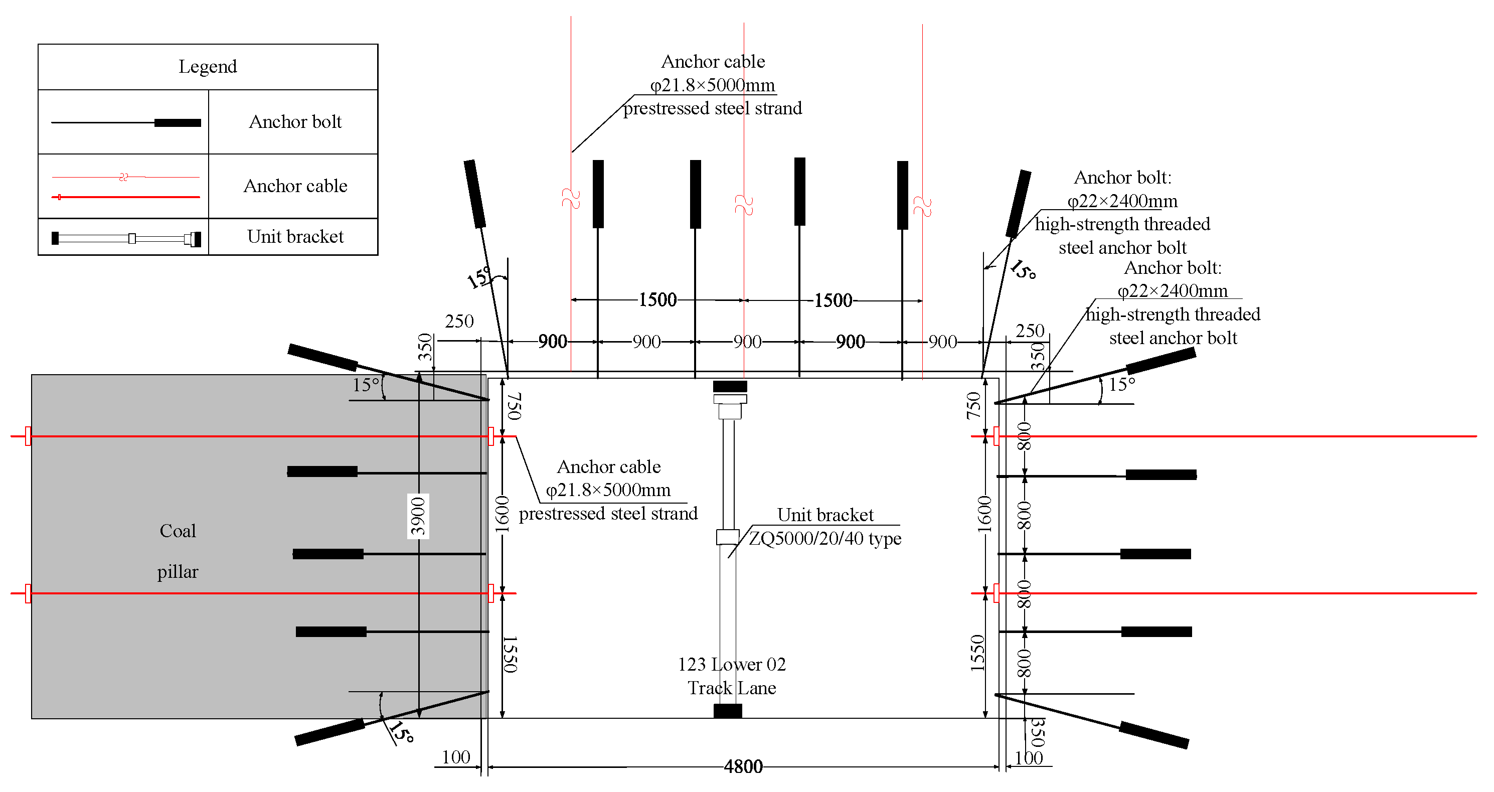
Based on the design dimensions of the roadway cross-section, the cross-sectional dimensions of the track roadway in the 123-02 working face are 5.0 m wide and 3.9 m high. Anchor cable support is designed and arranged on both sides of the coal pillar, with two and three anchor cables installed in each cross-section, respectively. The lateral restraint strength of the coal pillar is calculated based on a minimum preload of 220 kN for a single anchor cable; the specific results are shown in Table 2.
Table 2.
Small coal pillar through-anchor cable support scheme.
With the introduction of lateral constraints, the stress on the coal pillar changes from a unidirectional load to a bidirectional coupling effect, thereby significantly improving the residual strength and bearing capacity. Correspondingly, the ultimate bearing capacity σ1 of the small coal pillar under lateral stress is provided by Equation (29):
In the formula, σ0 is the residual compressive strength of the coal column under uniaxial compression conditions, MPa; σ3 is the lateral constraint stress provided by the through anchor cable, MPa; k is the lateral strengthening coefficient, ; and φ is the internal friction angle of the coal body, °.
The calculation yields k = 2.77.
Substituting the parameters in the table into Equation (29), the following results are obtained: when two and three anchor cables are configured on both sides of the cross-section, the ultimate bearing strength of the small coal pillar is 0.83 MPa and 1.06 MPa, respectively.
Considering the large slenderness ratio of the small coal pillar in the section, and the fact that its axial dimension is significantly larger than its width, its stress can be simplified and analyzed using a two-dimensional plane assumption. The edge effects at the front and rear ends can thus be ignored. Based on a coal pillar width of 4.5 m, the calculated bearing capacity results are shown in Table 3.
Table 3.
Analysis of the bearing capacity of small coal pillars.
Under these conditions, the ultimate bearing capacity of the two small coal pillars with through-cable anchors is 1.54 MPa, which is greater than the load per unit width of the coal pillar, P = 1.2 MPa, meeting the specified requirements.
Based on the actual site conditions, and considering both improving the extraction rate (i.e., reducing the coal pillar size) and the reasonable arrangement of anchor support density, a 4.5 m coal pillar was selected as the optimal support scheme, with two anchors installed on the coal pillar sidewall. Additionally, considering the actual site conditions, two more anchors were installed on the solid coal sidewall of the 123-02 track roadway for reinforcement.
5.1.3. Roadway Support Design Scheme (Strong Support)
During the advance process, the roadway exhibits spatially non-uniform characteristics due to mining activity: the advance zone initially bears the pressure of the advance support; after mining commences, the roof undergoes a “collapse-gradual change-stability” process; therefore, the rear support zone adjacent to the working face must be equipped with strong roof support. Only after the working face continues to advance, the spacing increases, and the roof movement enters a stable stage, can the temporary support behind the support be removed based on the procedure. The removal of support is based solely on the results of mine pressure monitoring; only when the roof of the remaining roadway section exhibits stable characteristics is the phased removal of temporary support equipment permitted.
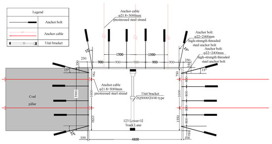
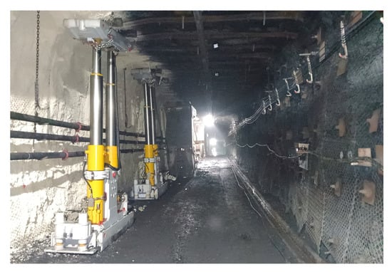
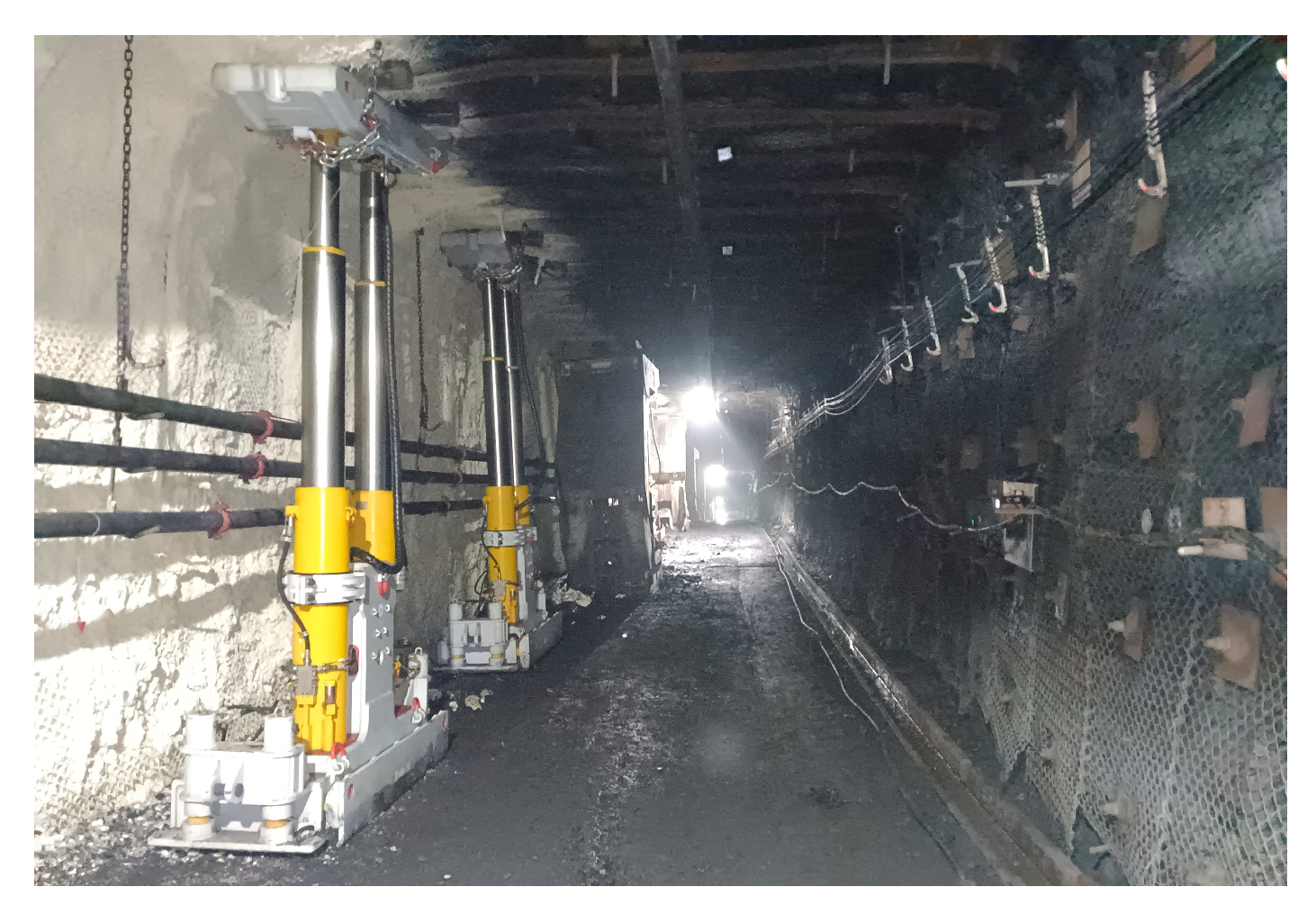
Since the middle section of the roadway bears most of the displacement and internal forces of the roof and floor, a ZQ5000/20/40 type unitized support is configured as a passive reinforcement system for the 50 m section at the forefront of the 123-02 return airway, in addition to the active support.
Layout principle: The supports are installed in a single row along the strike, with the axis falling near the roadway centerline and 2.4 m from the sidewalls; the construction sequence is performed after the completion of the pre-splitting blasting to avoid interfering with the conventional process flow. The on-site support cross-section is shown in Figure 5.
Figure 5.
The 123 Lower 02 Track Roadway Support Section Diagram.
5.2. Top Pressure Relief Parameter Optimization
Based on the theoretical calculation in Section 4, the theoretical roof cutting height is derived as 23.2 m. To verify the accuracy of this theoretical value and further determine the optimal engineering parameters, the numerical simulation schemes were designed around this calculated value. By comparing the stress distribution and roadway deformation under different cutting heights (including heights below and above the theoretical value), the simulation results serve to validate the theoretical model. The analysis below demonstrates that the optimal range identified by the simulation aligns consistently with the theoretical calculation of 23.2 m.
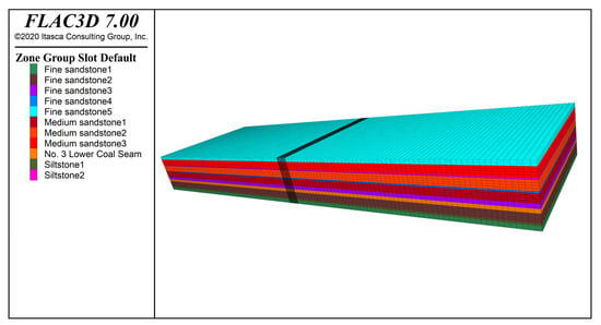
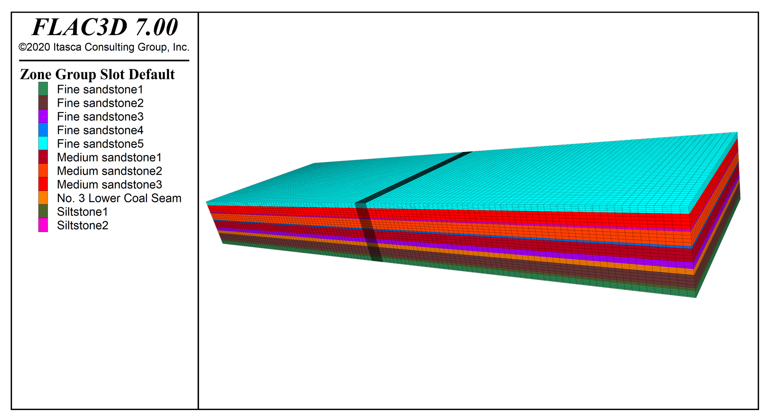
Based on the geological conditions and engineering specifications of the studied roadway, a numerical model with a length × width × height of 560 m × 165 m × 60 m was established at a constant scale using FLAC3D modeling. FLAC3D is based on the explicit finite difference method (FDM) to simulate the complex mechanical behavior of geological materials. The numerical model includes 11 rock layers, including the coal seam and the roof and floor. To reflect boundary effects, 60 m wide protective coal pillars were placed on both sides of the coal seam in the model. The boundary and load conditions were as follows: horizontal displacement was prohibited on all four sides, the bottom was vertically fixed, and a uniformly distributed surface load representing the self-weight of the overlying rock strata and surface soil was applied to the top, with a value of 11.56 MPa. The Mohr–Coulomb criterion was selected for the material constitutive model. The 123-02 track roadway was excavated first, followed by the 123-06 transport roadway, then the 123-06 working face, and finally the 123-02 working face. After model excavation was completed, the small coal pillar support stress curves for the two working face stages were extracted. The schematic diagram of the numerical model and mesh generation is shown in Figure 6.
Figure 6.
Schematic diagram of the numerical model and mesh generation.
The physico-mechanical parameters of the coal and rock mass were determined based on laboratory mechanical tests conducted on rock samples collected from the Fucun Coal Mine. Standard uniaxial compression and tensile tests were performed to obtain the intact rock properties. To account for the scale effect and the presence of discontinuities in the in situ rock mass, the laboratory data were reduced using the engineering geological reduction method to derive the final simulation parameters listed in Table 4.
Table 4.
Physical and mechanical parameters of coal and rock mass.
5.2.1. Cutting Height Simulation Optimization
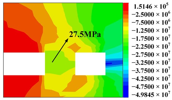
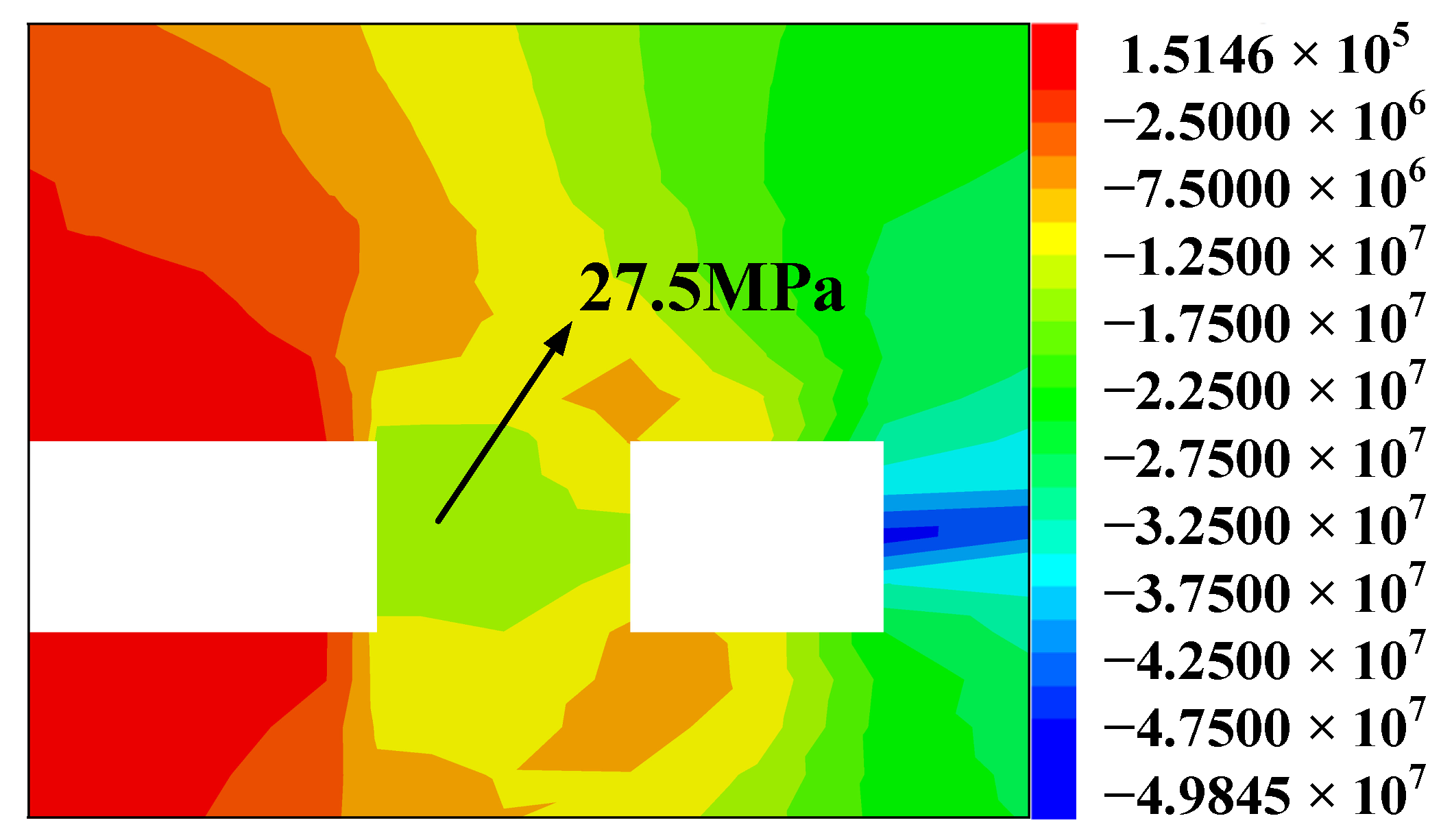
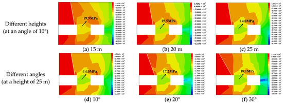
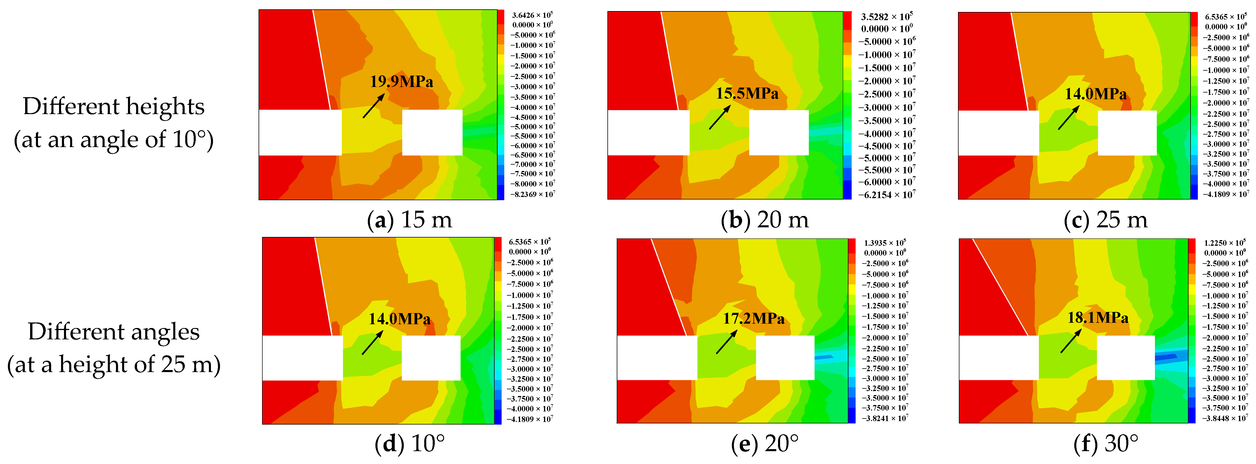
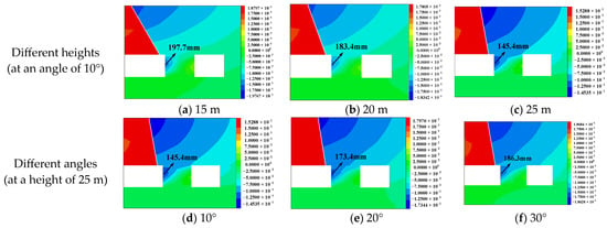
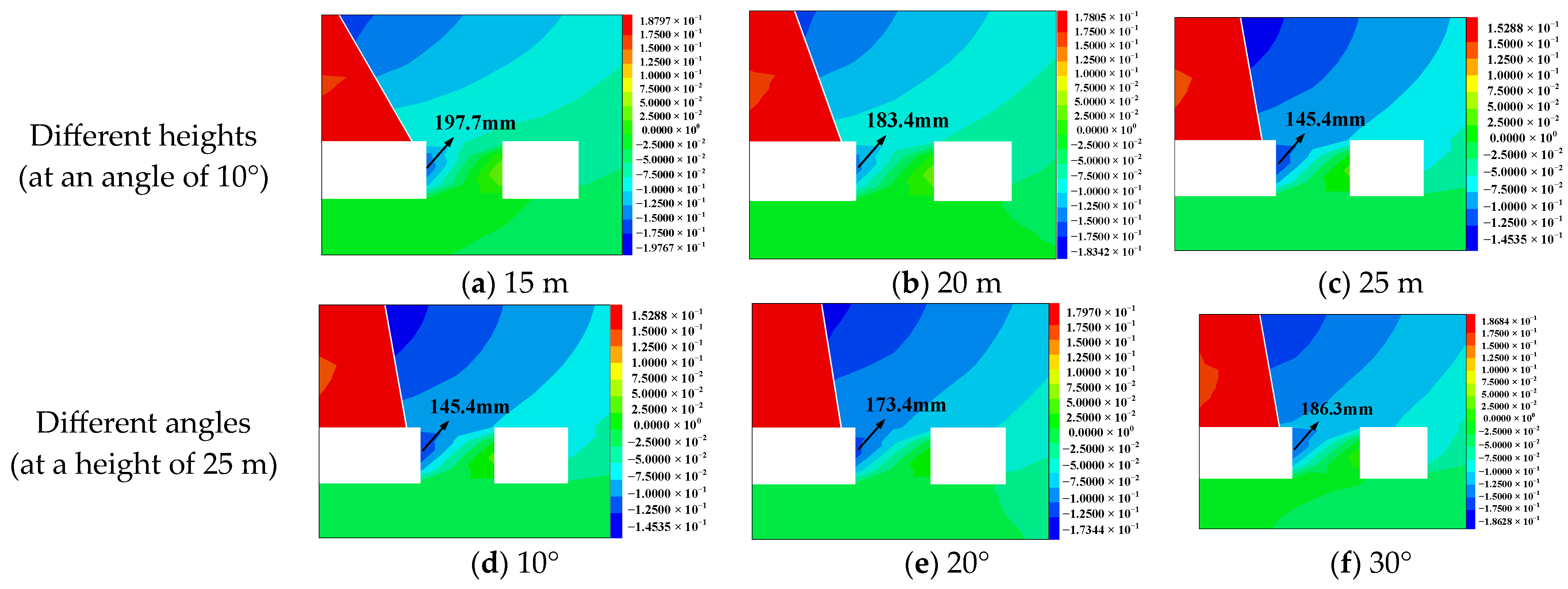
A cutting angle of 10° was selected. Based on the location of the key strata that play a dominant role in the roof strata, the cutting heights were determined to be 15 m, 20 m, and 25 m. A cutting height of 25 m was selected, and the cutting angles were determined to be 10°, 20°, and 30°. The vertical stress of the small coal pillar at different cutting heights and angles is shown in Figure 7, and the lateral displacement cloud diagrams of the small coal pillar at different cutting heights and angles are shown in Figure 8.
Figure 7.
Vertical stress distribution without roof cutting. (Unit: MPa).
Figure 8.
Stress cloud diagrams at different cutting heights and angles (Unit: MPa).
As shown in Figure 7 and Figure 8, the peak vertical stress of the coal pillar before roof cutting is 27.5 MPa. When the roof cutting angle is 10° and the cutting height is 15 m, the peak value drops to 19.9 MPa, a reduction of 27.6%, significantly alleviating stress concentration. This finding indicates that a 15 m roof cutting mechanically weakens the force transmission chain from the hard roof above the goaf to the overlying strata of the coal pillar. However, due to insufficient filling and compaction of the fallen gangue, delamination and large pores are still present at the roof–fill interface, making it difficult to form a stable support system, and the overall stress relief has not yet reached the ideal state. When the roof cutting height is increased to 20 m, the peak value further decreases to 15.5 MPa, a reduction of 43.6%. The larger cutting range effectively curbs the fracturing, rotation, and subsidence of the overlying strata, prompting the gangue in the goaf to construct a relatively stable load-bearing skeleton, working synergistically with the roof, thereby producing an enhanced inhibitory effect on the deformation of the surrounding rock in the roadway.
When the cutting height is increased to 25 m, the peak pressure is approximately 14.0 MPa, a decrease of 49.1%; however, the pressure relief benefits show diminishing marginal returns. Simultaneously, the height of the lateral combined cantilever beam increases, causing the pressure on the coal pillar roof to show a tendency to rise, significantly increasing operational costs and complicating construction. Considering both mechanical benefits and engineering feasibility, a cutting height of 23.2 m was determined to be the optimal solution after comparison.
5.2.2. Cutting Angle Simulation Optimization
Adjusting the roof cutting angle will reshape the location of the fracture zone in the roof strata and simultaneously change the distribution pattern of the supporting stress field on the coal pillar. Regarding the selection of the roof cutting angle, considering that a 0° cutting angle results in low sliding friction resistance on both sides of the cutting surface, although most effective in improving the stress environment of the goaf roadway, using pre-splitting roof cutting changes the roof on the cutting side of the 123-06 transport roadway from fixed support to simply supported. Furthermore, the pre-splitting position is more prone to roof collapse under mining stress, which is detrimental to the safety of the original roadway. Therefore, as shown in Figure 9, roof cutting angles of 10°, 20°, and 30° were selected, with corresponding peak stresses of 14.0 MPa, 17.2 MPa, and 18.1 MPa, respectively. The peak vertical stress within the coal pillar was reduced by 49.1%, 37.5%, and 34.2%, respectively. At a cutting angle of 10°, the peak supporting stress in the coal pillar is the lowest at 14.0 MPa, resulting in the lowest overall stress on the coal pillar.
Figure 9.
Lateral displacement contour maps under different cutting heights and angles (Unit: m).
The deformation results of the coal pillar sidewall under different cutting angles show that the deformation is the smallest, at 145 mm, when the cutting angle is 10°. Based on comprehensive theoretical calculations, it is concluded that the cutting angle with a cutting height of 23.2 m and a cutting angle of 9° produces the best decompression effect.
5.2.3. Analysis of Vertical Stress Results of Small Coal Pillars
- (1)
- Excavation of the 123 Lower 02 Return Airway and the 123 Lower 06 Transport Airway
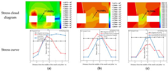
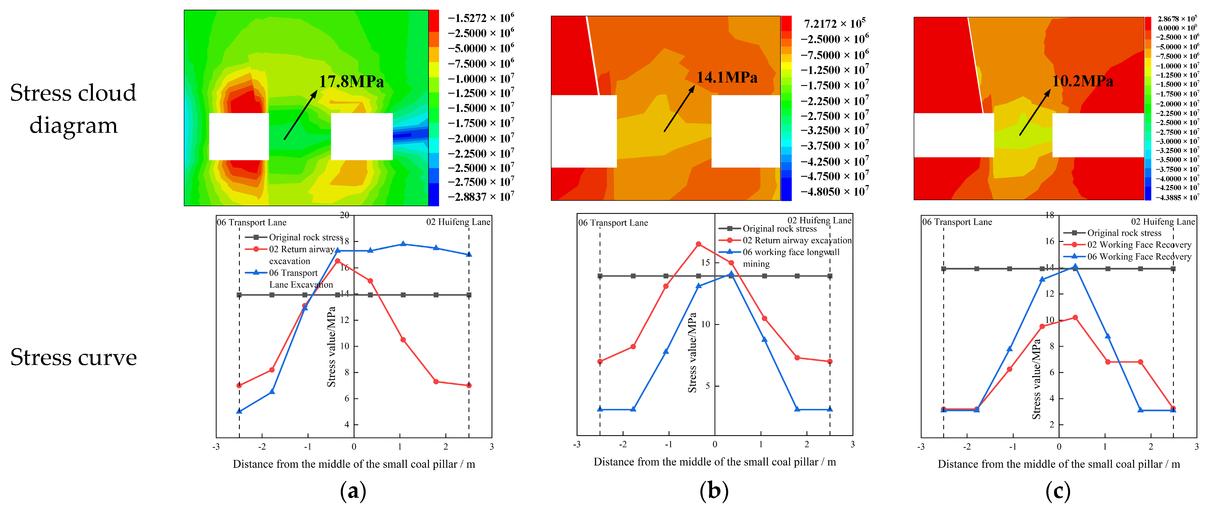
As shown in Figure 10a, the stress distribution of the small coal pillar after excavation is as follows: (a) The vertical stress cloud diagram shows that the stress at both edges is low, resulting in destructive deformation, whereas the elastic core remains in the middle; (b) after excavation of the 123 Lower 02 Return Airway, the support stress curve is symmetrically distributed, with a peak value of approximately 16.5 MPa and a stress concentration factor of 1.2. After excavation of the 123 Lower 06 Transport Airway, the stress within 1.5 m of the coal pillar edge is lower than the original rock stress; in comparison, the peak stress at 3–4.5 m reaches 17.8 MPa, with a stress concentration factor of 1.28.
Figure 10.
Vertical stress distribution of small coal pillars at different stages (Unit: MPa). (a) Excavation of the 123 Lower 02 Return Airway and the 123 Lower 06 Transport Airway; (b) Mining of the 123-06 working face; (c) Mining of the 123-02 working face.
- (2)
- Mining of the 123-06 working face
As shown in Figure 10b, the stress distribution of the small coal pillar after mining of the 123-06 working face is as follows: (a) The vertical stress cloud map shows that the stress in the middle of the coal pillar is lower than the original rock stress, and it has lost its bearing capacity; (b) the support stress curve shows a single-peak distribution, with a peak value of approximately 14.1 MPa, located 0.5 m away from the 123-02 return airway in the middle, indicating that the coal pillar is almost completely destroyed and the deformation is obvious, which may affect the stability of the 123-02 return airway.
- (3)
- Mining of the 123-02 working face
As shown in Figure 10c, the stress distribution of the small coal pillar after mining of the 123-02 working face is as follows: (a) The vertical stress cloud map shows that the change in stress of the coal pillar is not significant, and it is in a non-bearing state; (b) the support stress curve shows a single-peak distribution, with a peak value of approximately 10.2 MPa, which is lower than that of the 123-06 working face after mining, indicating that the degree of coal pillar destruction has been further aggravated; however, because it has been fundamentally destroyed in the early stage, the disturbance of the 123-02 working face has little impact.
5.2.4. Analysis of Lateral Deformation Results of Small Coal Pillars
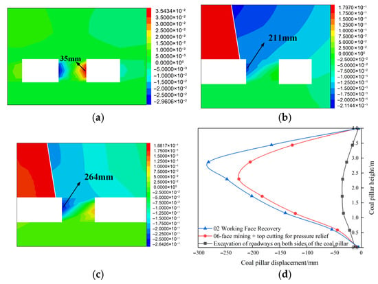
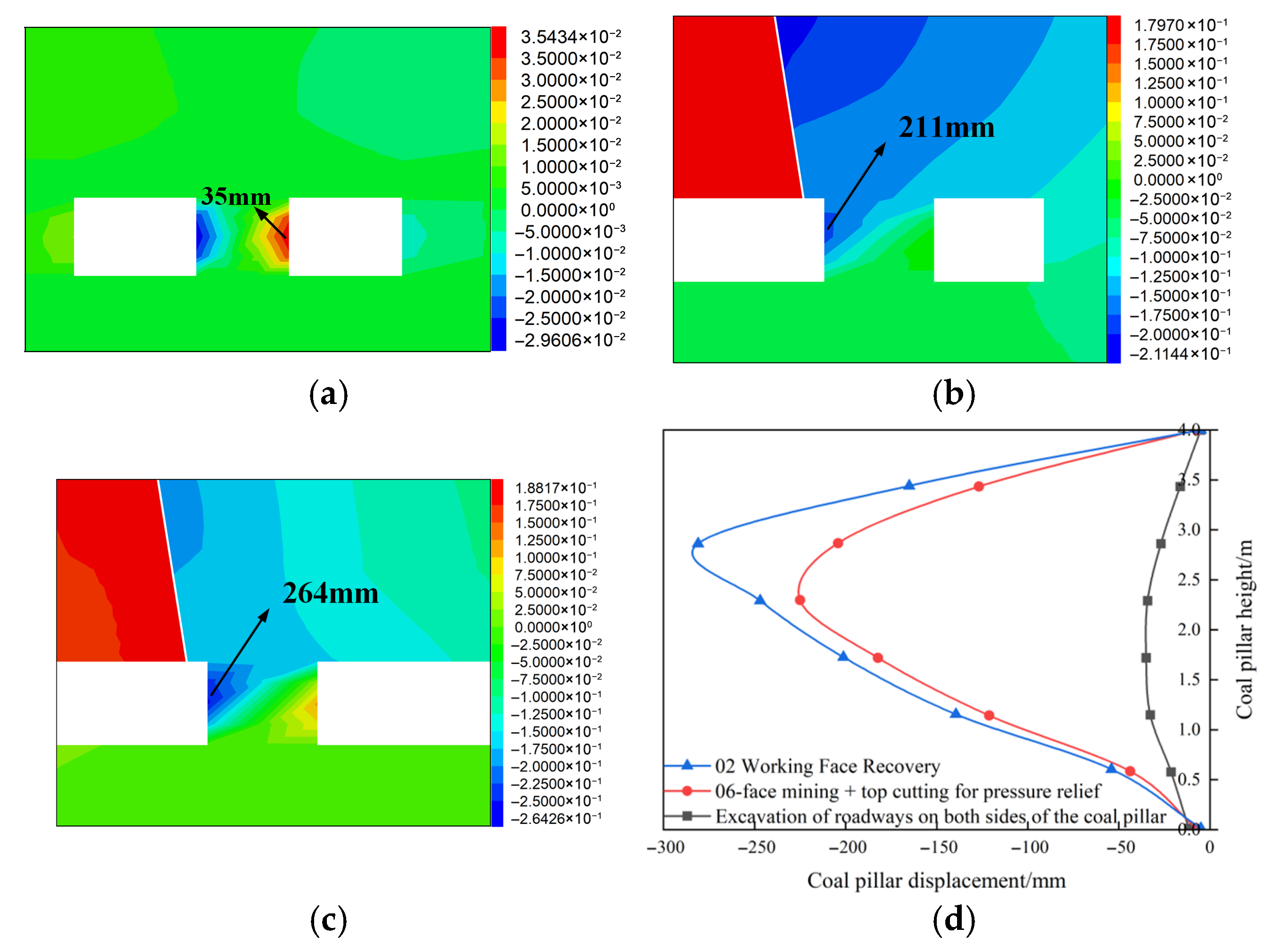
Figure 11a–c show the lateral deformation cloud maps of the coal pillar at different stages, and Figure 11d shows the displacement distribution curves of the coal pillar sidewall at different stages. From the figures, the following observations can be made: ① During the roadway excavation stage on both sides of the coal pillar, the coal pillar experiences relatively little mining disturbance, with a lateral displacement of only 35 mm. This finding indicates that the coal pillar is in a low-stress disturbance state at this stage, and its structure remains relatively stable. The deformation of the coal pillar sidewall mainly occurs within the shallow 2.0 m range, and the coal body in this area should be reinforced. ② With the mining of the 123-06 working face, mining activities should have led to stress concentration in the coal pillar and a significant increase in lateral deformation. However, by implementing roof cutting and pressure relief technology in the track roadway of the 123-02 working face while mining the 123-06 working face, the lateral displacement of the coal pillar was effectively controlled at 211 mm. The deformation of the upper part of the coal pillar sidewall is significantly greater than that of the lower part, and the deformation is mainly concentrated in the upper part of the roadway sidewall at 0–2.5 m. ③ Furthermore, during the mining phase of the 123-02 working face, due to the prior implementation of roof cutting and pressure relief, the lateral displacement of the coal pillar only increased to 264 mm, an increase of approximately 25.12%, far lower than the expected increase without control measures.
Figure 11.
Lateral Deformation Distribution of Small Coal Pillars at Different Stages (Unit: m). (a) Excavation of roadways on both sides of the coal pillar; (b) 123 Lower 06 working face longwall mining + roof cutting for pressure relief; (c) 123 Lower 02 working face mining; (d) Displacement curves of coal pillars at different stages.
Data show that the roof cutting and pressure relief technology not only effectively suppressed coal pillar deformation during the mining of the 123-06 working face but also continued to play a controlling role in the subsequent mining of the 123-02 working face, maintaining effective stability of the coal pillar under the disturbance of the thick, hard roof.
In terms of parameters, the roof cutting angle, cutting length, hole spacing/row spacing, and pre-tightening force should be considered in a coordinated manner; by comparing on-site monitoring and numerical calculations, it is necessary to reduce the peak value of lateral displacement and peak value of support stress to the target range [23,24].
6. Engineering Practice Effect Verification
6.1. Monitoring Methods and Survey Area Layout
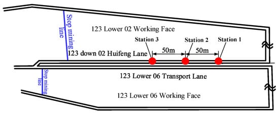
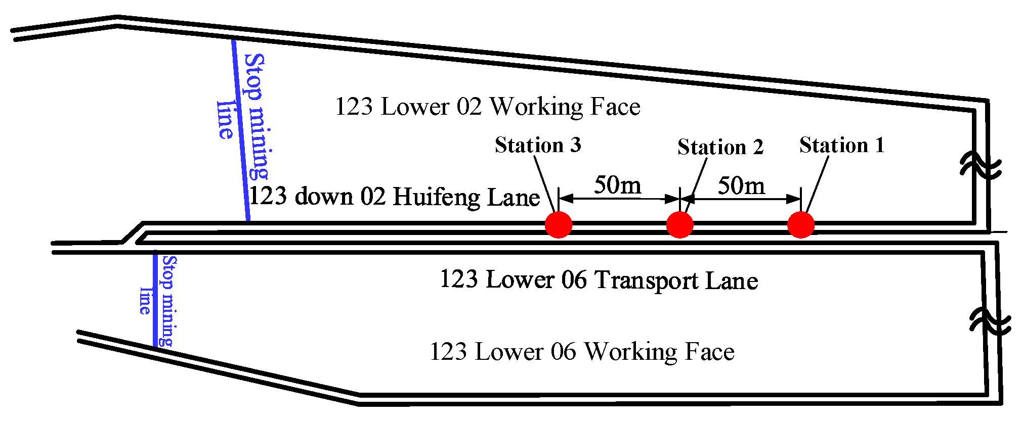
The monitoring scheme is designed as follows: Three observation stations are established in the test section of the 123-02 return airway, with a station spacing of 50 m. These stations are mainly used to record the working resistance of the anchor cables and the deformation of the surrounding rock during the mining process of the 123-06 working face. As shown in Figure 12, data acquisition begins at station #1 when the working face advances to a distance of approximately 200 m. Monitoring continues after the working face has passed until the distance between the station and the working face reaches 300 m, at which point monitoring ends.
Figure 12.
Layout diagram of the 123-02 return airway monitoring station.
6.2. Analysis of Monitoring Results
6.2.1. Analysis of Anchor Bolt (Cable) Working Resistance Monitoring Results
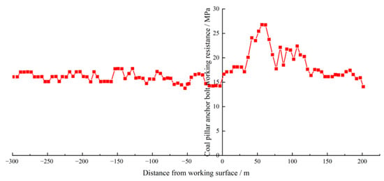
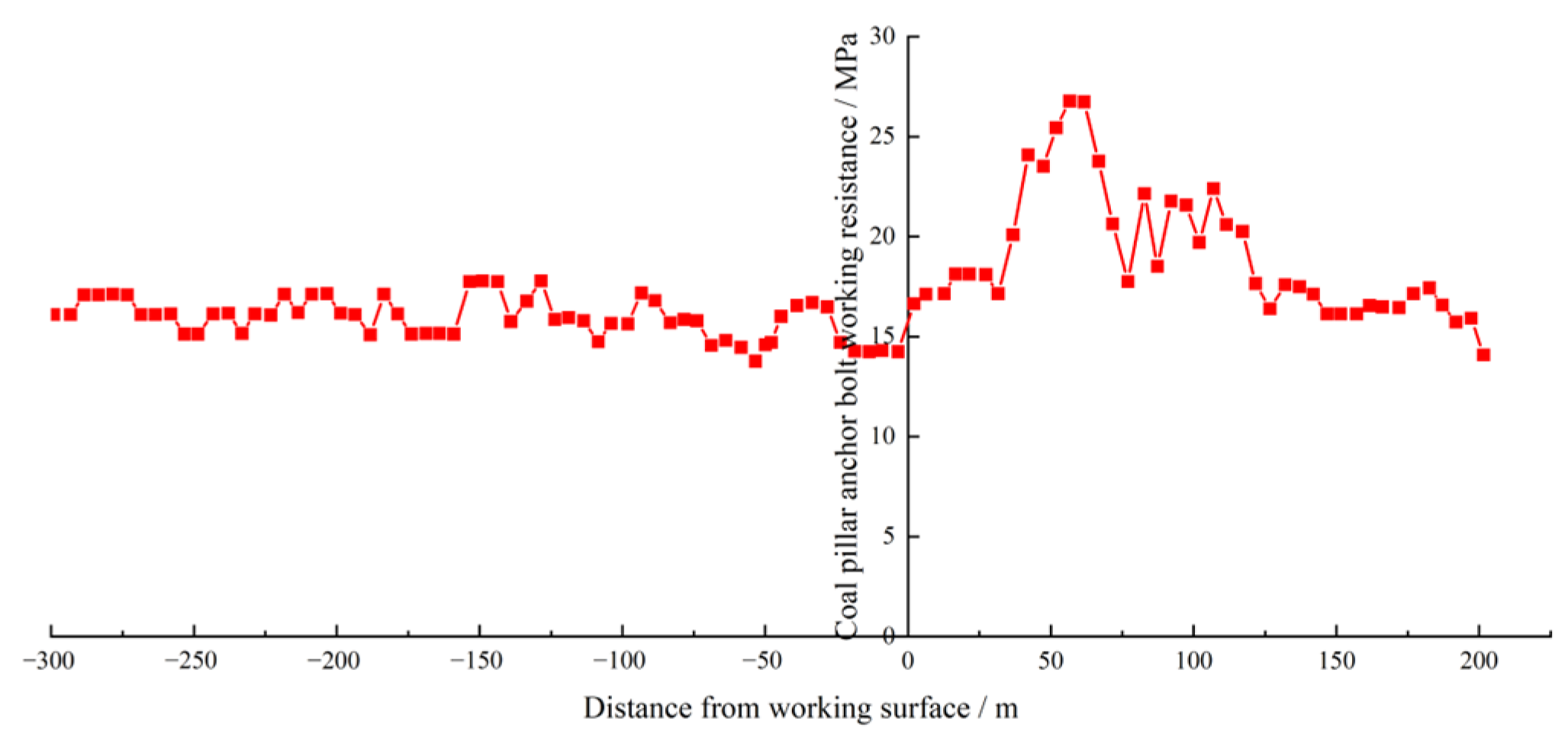
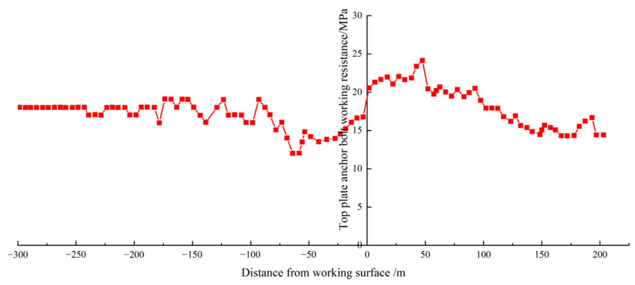
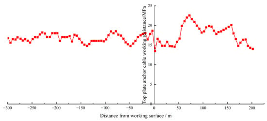
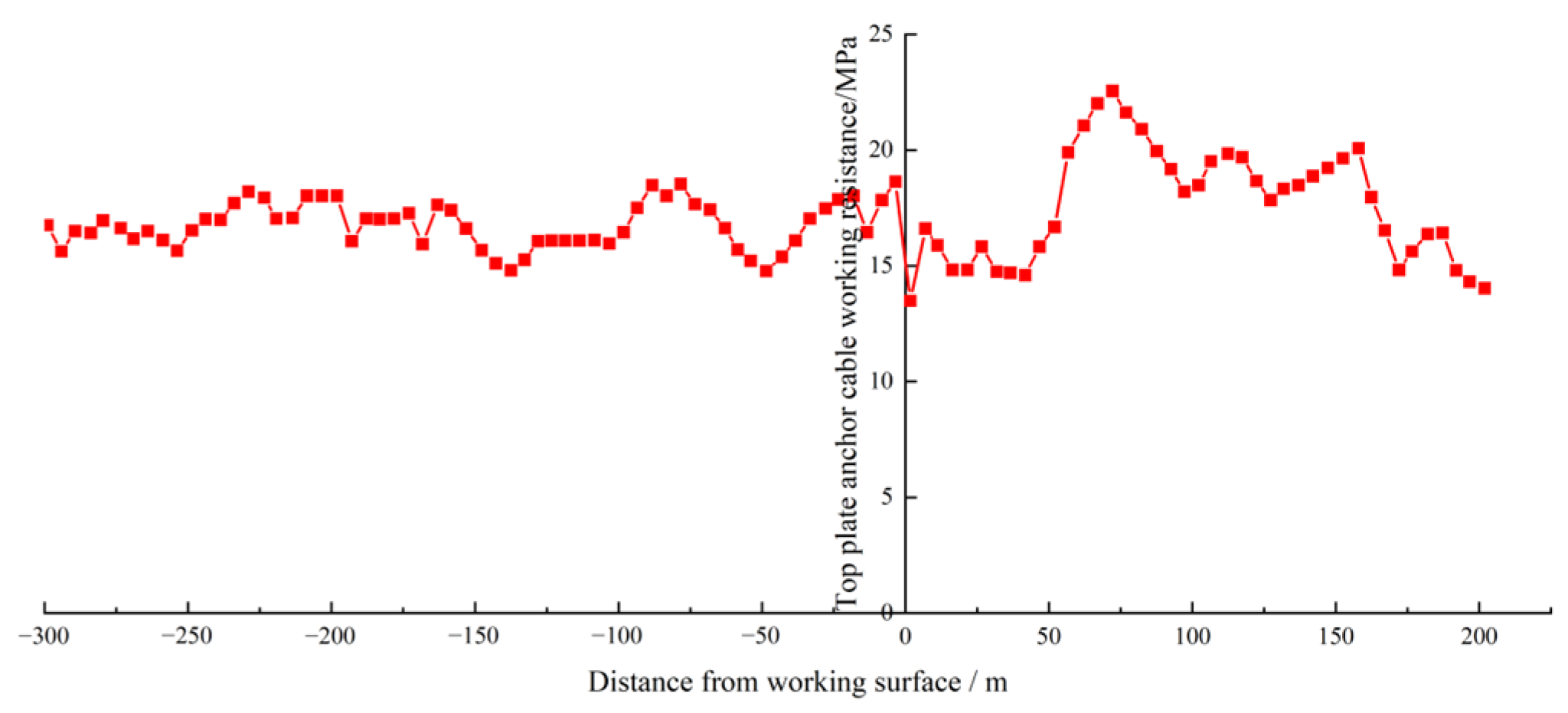
During the mining process at the 123-02 working face, the data recorded using the anchor bolt (cable) dynamometer were compiled and plotted as a curve showing the working resistance as a function of distance. As shown in Figure 13, Figure 14 and Figure 15, the coordinate axes correspond to the distance between the monitoring points and the front of the working face when the working face has not passed the monitoring station, while the negative direction corresponds to the distance after the working face has passed the monitoring station.
Figure 13.
Coal pillar side anchor bolt working resistance.
Figure 14.
Top plate anchor bolt working resistance.
Figure 15.
Anchor cable working resistance.
Analysis of Figure 13, Figure 14 and Figure 15 shows that as the 123-06 working face advances, the working resistance of the pressure-reducing anchor bolts (cables) increases with decreasing distance from the face after applying high preload. The resistance significantly increases within the range of 50–110 m from the working face. Specifically, the roof anchor cable reaches a peak of 22 MPa at approximately 75 m, the coal pillar anchor bolt reaches a maximum of 27 MPa at 60 m, and the roof anchor bolt reaches 24 MPa at 45 m. Monitoring indicates that the pre-support pressure mainly acts within the range of approximately 50–110 m from the working face. Under this effect, the support system has a significant restraining effect on surrounding rock damage and increases the bearing capacity of the surrounding rock.
After the working face passes the monitoring station, due to the repositioning and subsidence of the overlying strata in the goaf, the deformation of the roadway in the test section does not immediately stabilize. The resistance of the anchor bolts (cables) continuously adjusts, indicating that the support system is still functioning. When the working face advanced to approximately 250 m from the monitoring station, the resistance of the anchor bolts (cables) gradually stabilized, indicating that the movement of the basic roof beam was nearing its end and the roadway had entered a stable phase.
Based on the site conditions, the test section incorporated an integrated force-bearing system composed of anchor bolts (cables), support plates, steel strips, and metal mesh to achieve overall constraint and coordinated load-bearing. This system maintained its effectiveness even after the 123-06 working face was mined out, ensuring the stability of the goaf-side roadway and providing conditions for the next working face’s recovery.
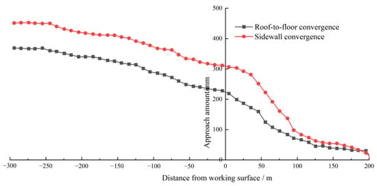
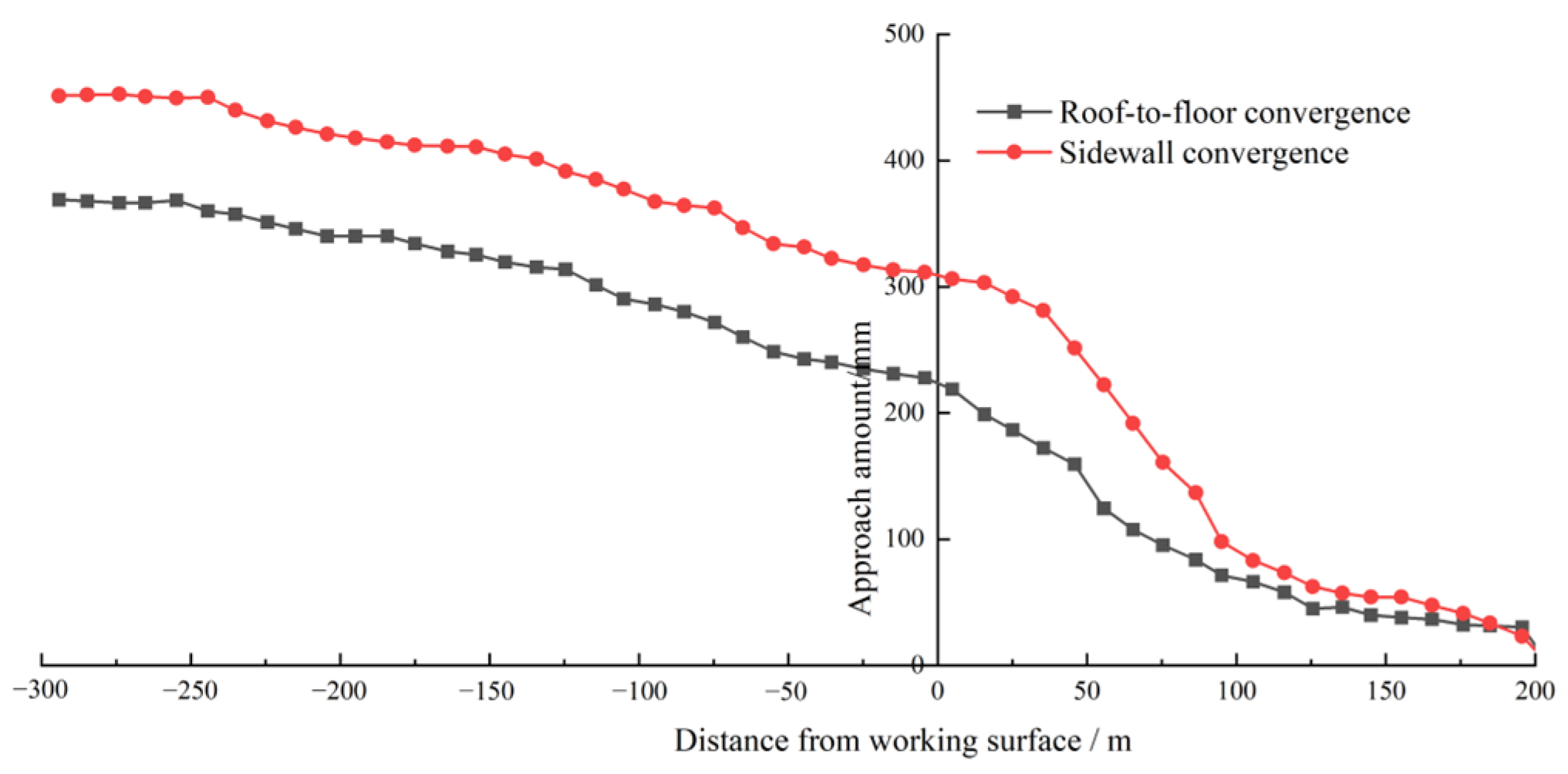
6.2.2. Roadway Surrounding Rock Deformation Monitoring Results
Based on the results presented in Figure 16, the convergence of the top and bottom plates and the two sidewalls begins to rise approximately 110 m from the working face, indicating that the advance support pressure enters this range. Upon entering the 50–80 m zone, the convergence rate increases sharply, and the advance pressure is at its peak influence period. After the working face passes the measuring point, the surrounding rock continues to deform gradually due to the continuous movement of the basic roof rock beam, only reaching a steady state after advancing approximately 250 m, indicating that the movement of the rock beam has essentially ceased at this stage.
Figure 16.
The moving distance of the tunnel roof and floor slabs and the two sides.
6.2.3. Unit Support Pressure Observation Results
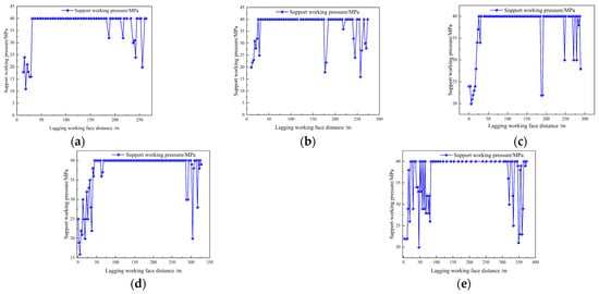
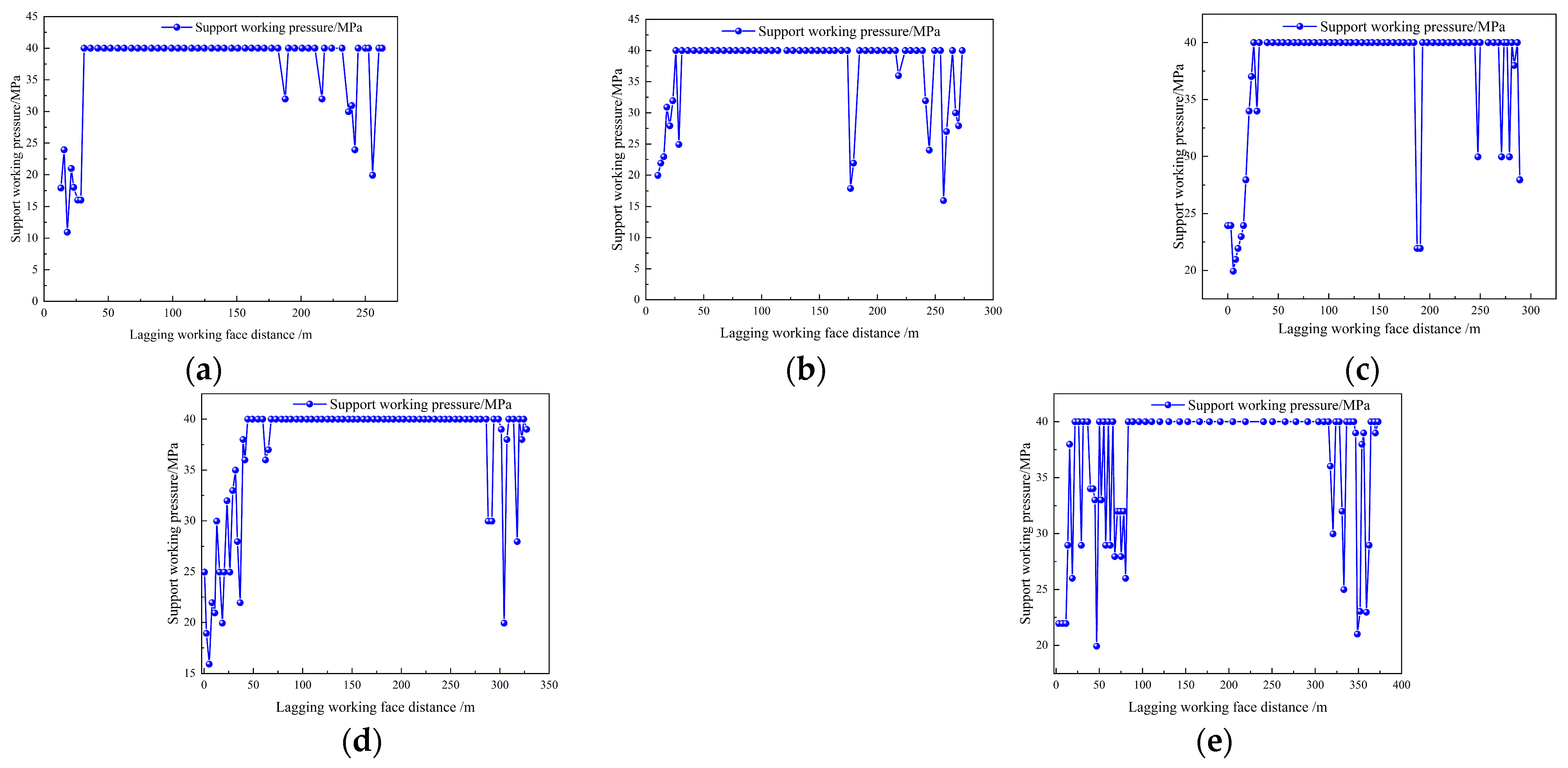
Based on the analysis results presented in Figure 17, for the support system during the roadway retention period, monitoring points were established on the coal pillar side to record the working resistance of the unit-type supports on-site. The observation results are shown in Figure 17 below.
Figure 17.
Unit support working resistance variation diagram. (a) Hydraulic support No. 1; (b) Hydraulic support No. 2; (c) Hydraulic support No. 3; (d) Hydraulic support No. 4; (e) Hydraulic support No. 5.
Considering all of the aforementioned factors, to ensure surrounding rock stability, it is recommended that the withdrawal starting point of the temporary unit supports be set at approximately 300 m behind the working face to achieve reuse; the on-site performance is consistent with the expected control target.
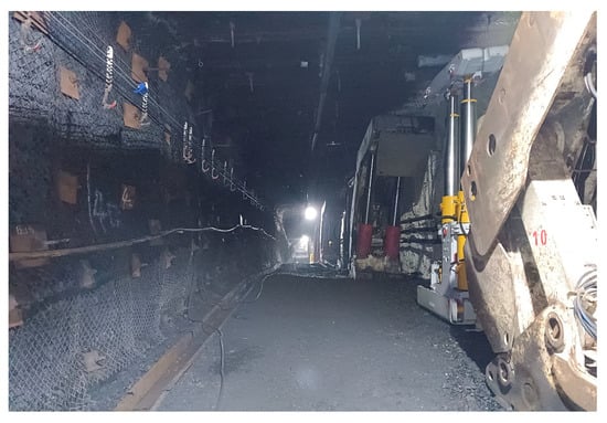
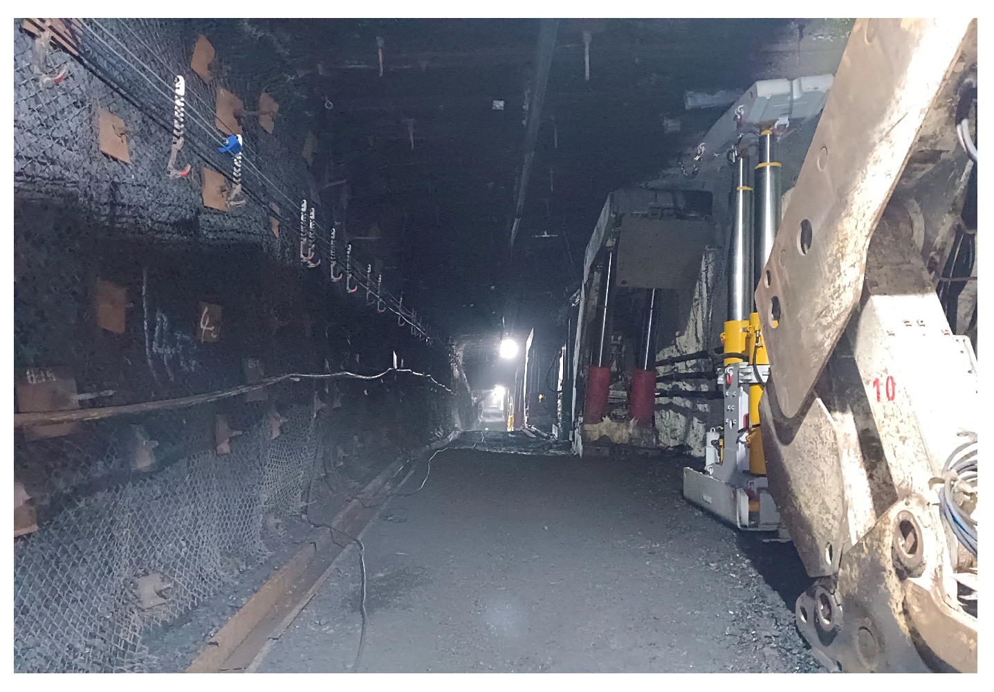
Compared with existing research results from studies on roadways without coal pillars and roadways along the goaf, the reasonable selection of self-forming roadway technology and roof cutting parameter configuration can effectively suppress roof subsidence and sidewall bulging, making the surrounding rock deformation stabilize more quickly; concurrently, taking into account the coal pillar width and floor stability conditions during the design can further reduce the continued development and secondary concentration of deformation in the later stage [25,26,27], as illustrated in Figure 18 and Figure 19.
Figure 18.
Roadway deformation during 123-06 mining.
Figure 19.
Roadway deformation after 123-06 mining.
7. Discussion
As a general overview, research on gob-side roadways and narrow/small coal pillars has consistently shown that stability is controlled by the coupled effects of mining disturbance, roof structure, and the capacity of the surrounding rock–support system to provide confinement and load sharing. Under thick and hard roof conditions, sectioned small coal pillars are prone to progressive deformation and instability because roof blocks tend to form strong load-transfer paths and impose sustained bending and extrusion demands on the pillar–roadway system. In this context, we interpret the observed large deformation risk as a flexural-dominated instability problem rather than a purely compressive failure mode. By establishing a segmented deflection–curve model under a continuous-medium assumption and deriving an analytical expression for deflection, the deformation response is linked to a set of dimensionless influencing factors, enabling a direct interpretation of how roof-induced loading and support actions govern pillar stability.
The numerical investigations further support this interpretation by demonstrating that overburden load transfer (represented by an equivalent bending effect) dominates the deflection response; in comparison, enhanced active support markedly suppresses deformation, indicating that instability is best mitigated through simultaneous “load-path weakening” and “confinement strengthening”.
The novelty and main contribution of this work are the establishment of a comprehensive, engineering-oriented stability logic for sectioned small coal pillars under thick and hard roofs: (i) we quantify deformation tendency via a deflection-based mechanical representation; (ii) identify dominant controls through dimensionless sensitivity; and (iii) translate these controls into a coordinated field strategy.
Specifically, the proposed “pressure relief–bundle control–strong support” framework is not a simple stacking of measures; it corresponds to three distinct mechanical functions aligned with the governing factors. First, roof cutting provides pressure relief by weakening the load-transfer chain from roof key blocks and shortening the effective cantilever action over the roadway–pillar system; our parameter determination and comparative numerical results provide evidence that an appropriate cutting geometry can substantially reduce the stress concentration borne by the coal pillar.
Second, through-anchor cables deliver bundle control by introducing lateral confinement that transforms the pillar from a weakly confined state into a biaxially constrained state, thereby elevating residual bearing performance and stabilizing deformation under repeated disturbance.
Third, the unit supports act as a strong support during the period when roof movement and time-dependent strata behavior (“caving–slow adjustment–stabilization”) demand a high-reserve passive bearing capacity, preventing delayed deformation from propagating into an uncontrollable regime.
In combination, these three functions form a closed-loop interpretation: pressure relief reduces external driving actions (roof-induced bending/stress transfer), bundle control increases internal resistance (confinement and residual strength), and strong support provides redundancy during the most demanding stages of strata motion. This coordinated interpretation is consistent with the field observations that the adopted scheme can significantly reduce deformation and ensure roadway formation quality.
Limitations: Although a direct field comparison without roof cutting was restricted by safety regulations, the numerical simulation in Section 5 serves as a comparative baseline. The contrast between the simulated high stress concentration (27.5 MPa) in the untreated scenario and the stabilized field monitoring results confirms the causality between the proposed synergistic control technology and the roadway stability. In this study, the theoretical model treats the coal pillar as a continuous elastic medium, neglecting the influence of pre-existing geological fissures and mining-induced plastic damage. This simplification leads to minor discrepancies between the theoretical predictions and the field monitoring data. Specifically, the field measured lateral displacement (264 mm) is slightly larger than the theoretical elastic calculation results. However, these field results still fall within the controllable range predicted by the FLAC3D simulation (approx. 220–280 mm), demonstrating a strong consistency. The monitoring curves of bolt and cable forces exhibited a distinct “rapid increase–stabilization” trend. This characteristic indicates that despite the model’s simplifications, the “pressure relief” mechanism successfully transferred high stress to the deep stable rock, and the “strong support” effectively restrained the shallow broken zone. This confirms that the proposed synergistic control technology remains robust and effective in engineering practice despite the theoretical idealizations. Several limitations should be recognized when generalizing the findings. First, the deflection–curve formulation is developed under a continuous-medium assumption and idealized boundary conditions; in practice, the coal pillar and surrounding rock may exhibit pronounced discontinuities, bedding anisotropy, and localized plastic softening that can alter the deformation mode and the effective stiffness distribution along the pillar height.
Second, the numerical evaluation of roof cutting and support response necessarily relies on constitutive simplifications and parameter representations that may not fully capture progressive fracturing, goaf compaction, and time-dependent behavior under repeated mining disturbances. Third, the bundle-control effect of through-anchor cables is quantified primarily through its confinement and bearing-capacity implications; however, the long-term evolution of cable–coal interaction (e.g., degradation under cyclic loading, local damage accumulation, and water-related weakening) may influence sustained effectiveness and should be validated under extended monitoring windows.
Lastly, while the proposed control pathway is demonstrated to be effective in the studied setting, parameter transfer to other mines should explicitly account for differences in roof lithology/structure, mining geometry, stress regime, and roadway service requirements.
In terms of future outlook, the authors of subsequent studies may proceed along four directions to broaden applicability and improve predictive fidelity. (1) Model refinement: incorporate discontinuities, anisotropy, and spatial variability into the deflection-based framework to better represent thick-hard roof roadways where structural planes govern deformation localization. (2) Time-dependent coupling: integrate roof movement stages and goaf compaction processes into a unified time-evolution model for deformation and support demand, enabling better design of the strong-support duration and withdrawal criteria. (3) Support–rock interaction under cyclic disturbance: evaluate the durability of bundle control by examining anchor–cable performance under repeated disturbances, including the evolution of confinement effectiveness and potential degradation mechanisms. (4) Data-driven calibration and multi-source monitoring: use field monitoring data to calibrate and update key parameters (e.g., effective bending demand and confinement response) and develop adaptive support strategies that link mechanical indicators (deflection tendency, confinement level, and roof movement stage) to real-time decision-making.
8. Conclusions
In this study, to address the deformation instability of gob-side roadways with small coal pillars under thick and hard roof conditions, a mechanical deflection model was established, and a synergistic control technology of “pressure relief–bundle control–strong support” was proposed and applied. The main conclusions are as follows:
- (1)
- A segmented deflection-curve model for small coal pillars was developed. It revealed that the lateral deformation of the pillar is primarily controlled by the rotation angle of the overlying rock strata and the stiffness of the pillar itself. The theoretical analysis indicated that optimizing the roof cutting height is the most critical factor in reducing the rotation angle and relieving stress concentration.
- (2)
- Theoretical calculations derived a roof cutting height of 23.2 m. Numerical simulations verified this result, showing that when the cutting height is within the range of 22–24 m and the cutting angle is 9°, the stress concentration in the coal pillar is minimized, effectively cutting off the stress transmission path.
- (3)
- A “pressure relief–bundle control–strong support” synergistic technology was proposed. Roof cutting provides pressure relief (reducing external load), the through-anchor cables provide bundle control (increasing the internal bearing capacity and integrity of the pillar), and the high-strength bolts provide surface confinement. This combination transforms the passive support mode into an active reinforcement system.
- (4)
- The industrial test in the Fucun Coal Mine demonstrated significant stability control. The monitored maximum lateral displacement of the coal pillar was controlled at 264 mm, and the roof-to-floor convergence was 350 mm. The roadway section met the requirements for safe mining, verifying the reliability and engineering value of the proposed method for similar geological conditions.
It should be noted that the proposed parameters are specific to the studied geological conditions. Future applications in different mines should consider the site-specific roof lithology and long-term creep behavior of the surrounding rock.
Author Contributions
Conceptualization, G.L. and X.L.; Formal analysis, C.L.; Funding acquisition, X.L. and Y.W.; Methodology, Y.W.; Visualization, X.S. and J.N.; Writing—original draft, G.L. and X.L.; Writing—review and editing, C.L. All authors have read and agreed to the published version of the manuscript.
Funding
The research described in this paper was financially supported by the National Natural Science Foundation of China (No. 52374130 and 52204100).
Data Availability Statement
The original contributions presented in this study are included in the article. Further inquiries can be directed to the corresponding author. The data are not publicly available due to confidentiality restrictions related to the mine site.
Conflicts of Interest
Author Changhu Li was employed by the Zaozhuang Mining Group Co., Ltd. Author Yujie Wu was employed by the company Shandong Energy Northwest Mining Group. The remaining authors declare that the research was conducted in the absence of any commercial or financial relationships that could be construed as a potential conflict of interest.
References
- Tang, D.; Zhao, W.; Zhang, J.; Ban, D. Reasonable width and control technology of narrow coal pillar in gob-side entry driving in deep-buried bump-prone coal seam. J. Min. Sci. Technol. 2024, 9, 921–931. [Google Scholar] [CrossRef]
- Zhang, H.; Wan, Z.; Zhang, Y.; Teng, T.; Chen, Y.; Wei, Z. Stability control of narrow coal pillars in the fully-mechanized gob-side entry during sequenced top coal caving mining. J. China Coal Soc. 2021, 46, 1211–1219. [Google Scholar] [CrossRef]
- Liang, M.; Zhang, B. Reasonable parameters of pre-splitting blasting pressure relief of residual coal pillar in upper coal seam. Coal Eng. 2023, 55, 82–86. Available online: https://d.wanfangdata.com.cn/periodical/CiBQZXJpb2RpY2FsQ0hJU29scjkyMDI2MDExMjE3MDQyNhINbXRnYzIwMjMwNDAxNRoIYzVvZnRvZno%3D (accessed on 25 January 2026).
- Huang, W.P.; Zhao, T.Y.; Jiang, D.H.; Guo, X.; Zheng, Y.; Wang, X. Arrangement of double entry driving with a narrow coal pillar in the middle and stability control technology of surrounding rock. Chin. J. Rock Mech. Eng. 2023, 42, 617–629. [Google Scholar] [CrossRef]
- Zhang, G.; Jiang, J.; Deng, Z.; Zhao, S.; Si, R.; Gao, J.; Xu, L.; Zhang, A. Research on pressure relief technology of deep and shallow hole combined blasting under retaining small coal pillar in double roadway excavation. Coal Sci. Technol. 2023, 51, 33–40. [Google Scholar] [CrossRef]
- Wang, W. Study on surrounding rock stress and control technology of goaf side roadway. China Min. Mag. 2021, 30, 144–152. [Google Scholar] [CrossRef]
- Fan, H.G.; Lu, Z.J.; Jiang, D.J. Deformation mechanism and surrounding rock control of advance heading in fully mechanized working face. Coal Eng. 2024, 56, 39–44. Available online: https://d.wanfangdata.com.cn/periodical/CiBQZXJpb2RpY2FsQ0hJU29scjkyMDI2MDExMjE3MDQyNhINbXRnYzIwMjQwMzAwNxoIYXMzbmQ1bHM%3D (accessed on 25 January 2026).
- Wang, M. Research on complete set of technology for “pressure relief-reinforcement” surrounding rock control in gob-side entry driving with small coal pillars in medium-thick coal seams. China Min. Mag. 2023, 32, 118–125. [Google Scholar] [CrossRef]
- Du, Y.J. Research on High Pressure Hydraulic Roof Cutting and Pressure Relief Technology for Hard Roof in Roadways. Shandong Coal Sci. Technol. 2023, 41, 68–70+74. [Google Scholar] [CrossRef]
- Wang, Q.; He, M.C.; Wang, Y.; Liu, J.; Xue, H. Research progress and prospect of automatically formed roadway by roof cutting and pressure relief without pillars. J. Min. Saf. Eng. 2023, 40, 429–447. [Google Scholar] [CrossRef]
- He, M.; Zhao, L. Parameter design and practice of retaining roadway along goaf for roof cutting and pressure relief in medium thick coal seam. China Min. Mag. 2022, 31, 88–96. [Google Scholar] [CrossRef]
- Wang, W.; Li, Z.; Du, F.; Cao, Z.; Shi, J.; Zhai, M.; Liu, M. Study on the evolution law of failure depth of large mining height and ultra-wide working surface. Sci. Rep. 2026, 16, 665. [Google Scholar] [CrossRef] [Scilit]
- Lin, H.; Zhang, W.; Guo, S.; Zhang, X.; Wang, L.; Zhang, J. Study on the energy evolution mechanism and fractal characteristics of coal failure under dynamic loading. ACS Omega 2025, 10, 54710–54719. [Google Scholar] [CrossRef] [Scilit]
- Wang, P.X.; Liu, J.N.; Feng, G.R. Stress distribution and failure characteristics of a longwall panel floor with a negative gate pillar. Chin. J. Rock Mech. Eng. 2023, 42, 194–211. [Google Scholar] [CrossRef]
- Liu, S.; Li, X.; Zhu, W.; Fu, M.; Zhang, D.; Peng, B. Roof cutting mechanism of dense drilling in gob-side entry retaining and determination method of key parameters. Coal Sci. Technol. 2024, 52, 23–33. [Google Scholar] [CrossRef]
- Shi, W.; Li, Z.; Liu, C.; Lü, Y.; Zhang, H.; Yang, T. Study on optimization of key parameters of thick hard roof cutting and retaining roadway in inclined coal seam. Coal Sci. Technol. 2024, 52, 11–24. [Google Scholar] [CrossRef]
- He, M.C. Theory and engineering practice for non-pillars mining with automagical entry formation and 110 mining method. J. Min. Saf. Eng. 2023, 40, 869–881. [Google Scholar] [CrossRef]
- Zhang, W.; Zhang, Q.J.; Xie, X.H.; Yang, B.; Shi, Y.; Yang, Y.; Shi, Q. Optimization on Key Parameters of Roof Cutting and Gob-Side Entry Retaining at the Soft and Hard Composite Roof in Medium Thick Coal Seams. Min. Res. Dev. 2023, 43, 12–18. [Google Scholar] [CrossRef]
- Zhang, Z.Z.; Bai, J.B.; Wang, X.G.; Xu, Y.; Yan, S.; Liu, H.; Wu, W.; Zhang, W. Review and development of surrounding rock control technology for gob-side entry retaining in China. China Coal Soc. 2023, 48, 3979–4000. [Google Scholar] [CrossRef]
- Xu, X.; He, F.; Lü, K.; Wang, D.; Li, L.; Zhai, W. Research on reasonable cutting roof parameters of gob side entry retaining by roof cutting in thick and hard roof. J. China Coal Soc. 2023, 48, 3048–3059. [Google Scholar] [CrossRef]
- Cui, H.T. Research on Pillarless Mining Technology of Fully Mechanized Mining Face. Coal Mine Mod. 2025, 34, 155–160. [Google Scholar] [CrossRef]
- Zhu, Y.; Yang, K.; Li, Y.L. Stability analysis and control strategy of layered floor of mining roadway under different coal pillar sizes. J. Min. Safety Eng. 2023, 40, 467–479. [Google Scholar] [CrossRef]
- Xu, X.T. Optimization of roof cutting parameters and surrounding rock control method for gob-side entry retaining under thick and hard roof. Meitan 2023, 32, 72–76+83. [Google Scholar] [CrossRef]
- Ma, J.; Lyu, C.; Liao, Y. Research on the width of narrow coal pillars in goaf excavation roadway of fully mechanized caving face in inclined thick coal seam. China Min. Mag. 2024, 33, 317–322. [Google Scholar] [CrossRef]
- Kang, H.; Zhang, X.; Wang, D.; Tian, J.; Yi, Z.; Jiang, W. Strata control technology and applications of non-pillar coal mining. J. China Coal Soc. 2022, 47, 16–44. [Google Scholar] [CrossRef]
- Chen, Z.; Zhang, Y. Research and application of coordinated control technology for surrounding rock stability of gob-side entry driving with narrow coal pillar. Min. Saf. Environ. Prot. 2023, 50, 65–70. [Google Scholar] [CrossRef]
- Wang, B.; Feng, G.; Jiang, F. Research on segment coal pillar width based on rock burst prevention in Shaanxi–inner Mongolia deep mines. J. Taiyuan Univ. Technol. 2023, 54, 443–450. [Google Scholar] [CrossRef]

Disclaimer/Publisher’s Note: The statements, opinions and data contained in all publications are solely those of the individual author(s) and contributor(s) and not of MDPI and/or the editor(s). MDPI and/or the editor(s) disclaim responsibility for any injury to people or property resulting from any ideas, methods, instructions or products referred to in the content. |
© 2026 by the authors. Licensee MDPI, Basel, Switzerland. This article is an open access article distributed under the terms and conditions of the Creative Commons Attribution (CC BY) license.