


Abstract
Diamond particles tend to disperse non-uniformly during the electroplating sand-setting process of diamond wire manufacture. To address this problem, the gas–liquid–solid three-phase flow characteristics in a baffled semi-circular reciprocating mixing tank were numerically analyzed by means of CFD(computational fluid dynamics). A VOF–DPM (Volume of Fluid–Discrete Phase Model) coupled gas–liquid–solid model was established to investigate the flow-field evolution within a stirring cycle, the velocity distribution characteristics, and the influence of the reciprocating frequency on mixing performance; the particle mixing uniformity of the reciprocating stirring device was further verified by sampling experiments. The results show that three typical dynamic vortex regions are formed in the tank, located above and below the stirring plate and outside the baffle, and the flow structure evolves periodically with the motion of the stirring plate. The reciprocating motion of the flat plate exerts a pronounced velocity-amplification effect on the fluid: the maximum axial velocity in the tank can reach 1.95 times the maximum velocity of the stirring plate. Increasing the reciprocating frequency raises the overall flow velocity and improves the uniformity of the velocity distribution, but does not change the basic flow pattern. Under the process condition of 0.5 Hz, which was evaluated experimentally by multi-point sampling (the CFD simulations were performed at 0.25, 0.62, and 1.00 Hz), the relative standard deviation of the diamond particle mass fraction is 4.62%, satisfying the requirements of the diamond wire electroplating sand-setting process. The results provide a theoretical basis for the structural optimization and process parameter regulation of reciprocating stirring devices for diamond wire sand-setting.
1. Introduction
Diamond wire is a highly efficient cutting tool in which diamond particles are firmly bonded onto the surface of a steel wire substrate by electroplating, and it is widely used for cutting hard and brittle materials such as photovoltaic silicon wafers, sapphire, and ceramics [1,2,3]. During the sand-setting electroplating stage, the dispersion uniformity of the diamond particles in the plating bath directly determines the consistency of particle attachment on the wire surface [4,5,6] and is a core factor affecting the cutting performance and service life of the diamond wire [7,8,9]. Developing an efficient, low-damage stirring process [10] that achieves the uniform suspension of diamond particles in the plating bath [11,12] is therefore a key issue in diamond wire manufacture.
Conventional impeller-based rotary stirring readily produces a central vortex dead zone [13], and high-speed impellers can cause impact damage to the crystal form and the pre-plated coating of diamond particles [14,15], making it difficult to satisfy the quality requirements of the sand-setting process. Reciprocating stirring drives the fluid flow through the periodic reciprocating motion of a stirring element; it has no central dead zone and exerts a mild shear action without damaging the particle morphology, giving it unique advantages in the field of multiphase suspension and mixing [16]. In recent years, reciprocating (oscillatory) stirring technology has been gradually applied to industrial processes such as heat and mass transfer, multiphase mixing, particle suspension, and biological fermentation, and related studies have shown that oscillation-induced vortices can effectively enhance liquid–solid mixing and particle suspension [17,18].
A series of studies has been carried out on the flow characteristics of reciprocating stirring. Hirata et al. [19] investigated the chaotic mixing characteristics caused by reciprocating a disk in a cylindrical vessel and found that reciprocating motion can induce complex flow structures and improve the mixing efficiency. Komoda et al. [20] measured the turbulent flow characteristics induced by a reciprocating disk in a cylindrical vessel and obtained the distribution law of the turbulence. Kordas et al. [21] compared the mixing efficiency of rotary and reciprocating agitation and demonstrated that reciprocating stirring exhibits superior mixing performance under certain operating conditions. Fan et al. [22] found that, under the reciprocating motion of the agitator, a large-scale vortex is generated below the impeller, and this vortex phenomenon improves the mixing effect. The stirring of diamond particles involves a gas–liquid–solid three-phase system, and researchers have realized multiphase coupling by means of the VOF–DPM approach [23,24]. Liu et al. [25] employed VOF–DPM coupling to investigate the mixing uniformity of concrete. Chen et al. [26] used this method to improve the spraying uniformity of droplets on complex surfaces. The above studies indicate that a reciprocating stirring device in which the gas–liquid–solid three-phase flow is realized by the VOF–DPM coupling method can effectively improve the dispersion uniformity of diamond particles in the plating bath.
In this study, targeting the process requirements of diamond wire electroplating sand-setting, a baffled semi-circular flat-plate reciprocating stirring device was taken as the research object. A transient CFD numerical model was constructed using the dynamic mesh and user-defined function (UDF) techniques, and the gas–liquid–solid three-phase flow was simulated with a VOF–DPM coupled model. The vortex evolution, velocity distribution, turbulent kinetic energy distribution, and particle motion characteristics within a single stirring cycle were systematically investigated, and the influence of the reciprocating frequency on the flow and mixing performance was analyzed. Multi-point sampling experiments were also carried out to determine the particle mixing uniformity and to verify the feasibility of the device.
2. Materials and Methods
2.1. Structure and Working Principle of the Stirring Device
2.1.1. Model of the Stirring Device
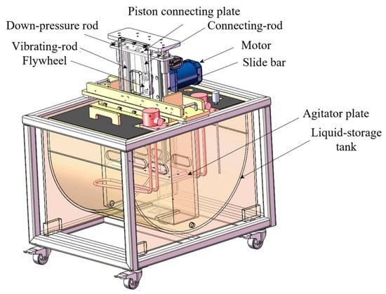
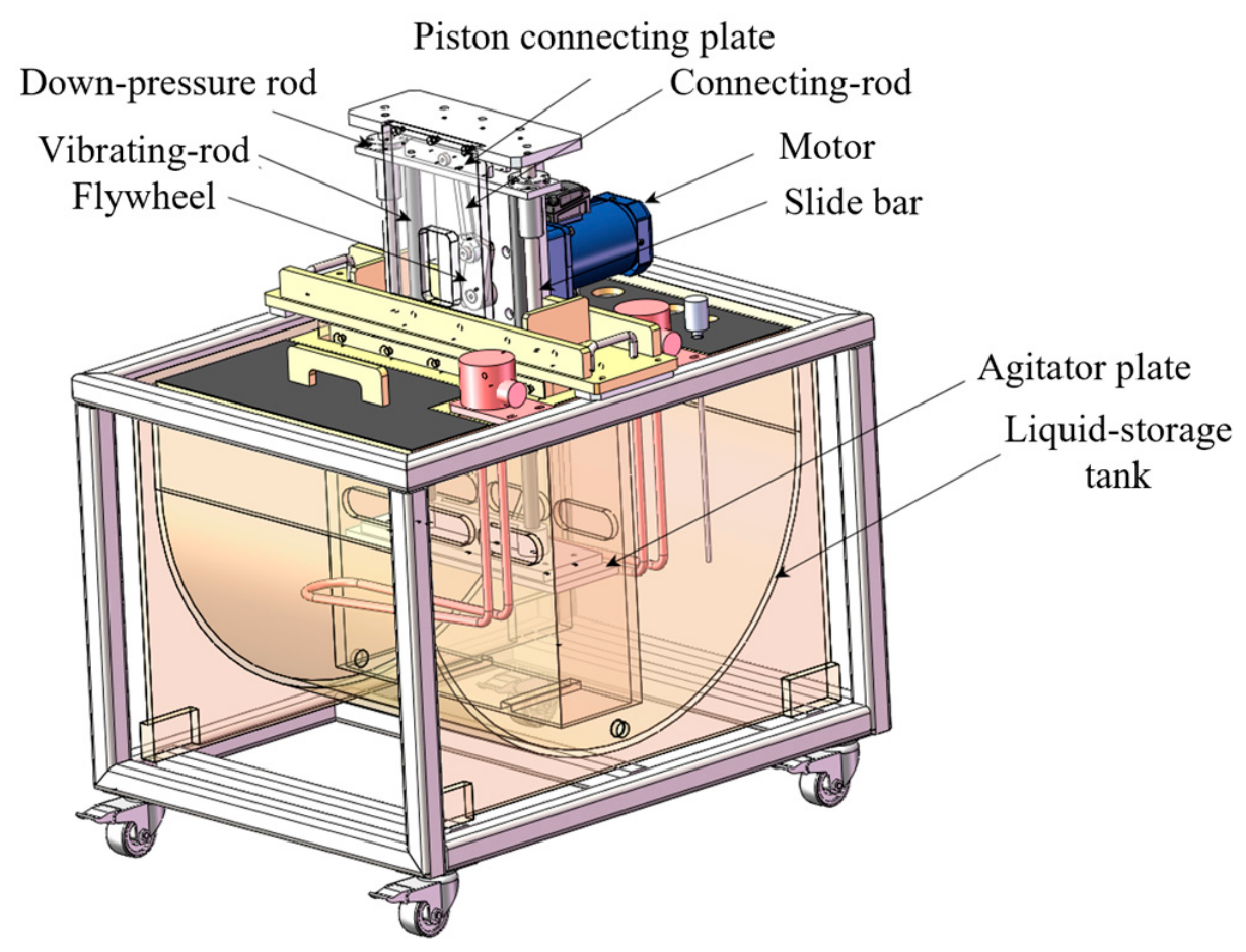
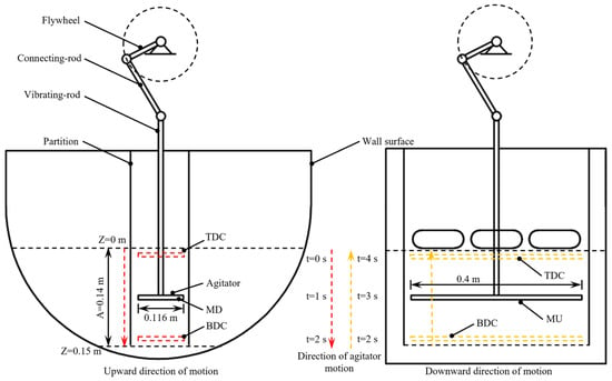
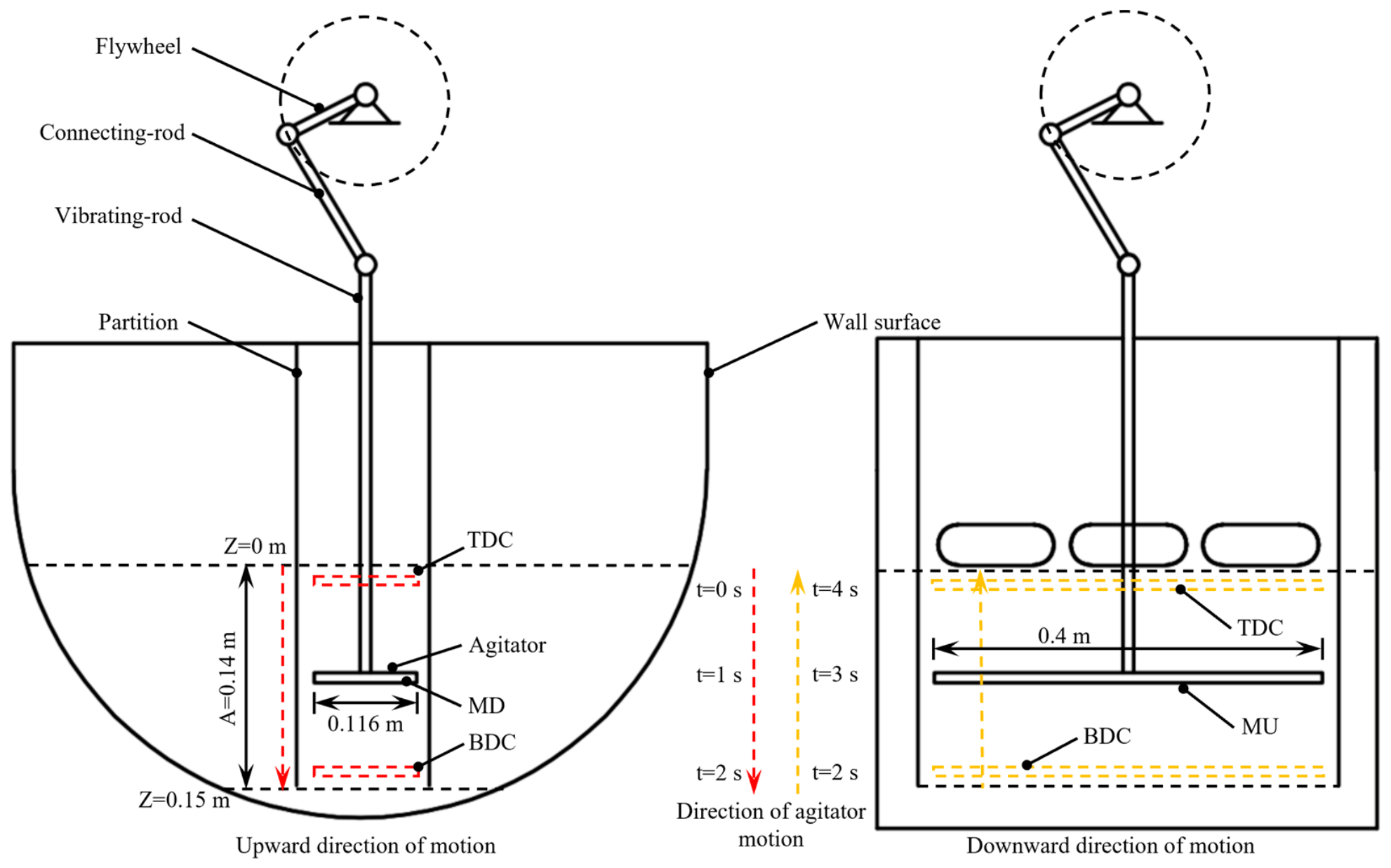
The reciprocating stirring device mainly consists of a flywheel, a connecting rod, a down-press rod, a rectangular stirring plate, and a semi-circular mixing tank with a baffle, as shown in Figure 1. The rotary motion of the flywheel is converted by the linkage mechanism into the vertical reciprocating linear motion of the stirring plate, which drives the fluid in the tank and realizes mixing; the working principle is shown in Figure 2.
Figure 1.
CAD model of the mixing tank.
Figure 2.
Schematic diagram of the structure of the reciprocating stirring device.
The mixing tank has a semi-circular cross-section with a radius of R = 0.34 m. The stirring plate is a rectangular flat plate with dimensions of 0.40 m (length) × 0.116 m (width) × 0.01 m (thickness). A vertical baffle is installed inside the tank, forming a clearance flow channel with the stirring plate, which serves to enhance the fluid shear and vortex generation.
2.1.2. Kinematic Equations of the Stirring Device Model
Owing to the kinematic characteristics of the crank-and-connecting-rod mechanism, the instantaneous displacement and velocity of the stirring plate contain higher-order harmonic components. By analyzing the geometric relationship between the connecting-rod length L and the amplitude A, the instantaneous displacement z(t) of the stirring plate can be expressed as
Differentiating with respect to time yields the instantaneous velocity w(t) of the stirring plate:
where A is the amplitude, f is the reciprocating frequency (Hz), and L is the connecting-rod length.
To quantitatively describe the flow-field characteristics at different phases within a single cycle, a dimensionless relative time is introduced, in which time is normalized by the reciprocating period T of the stirring plate, with T = 1/f. In this paper, relative instants within the cycle are denoted in the form 0.125T–1T, defined as follows: 0T corresponds to the stirring plate being located at the top dead centre (TDC), 0.5T corresponds to the stirring plate moving to the bottom dead centre (BDC), and 1T corresponds to the stirring plate returning to the TDC, completing one full reciprocating cycle.
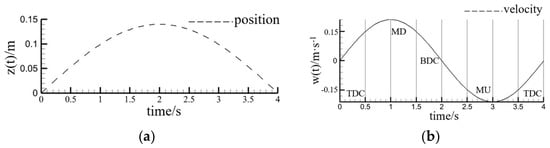
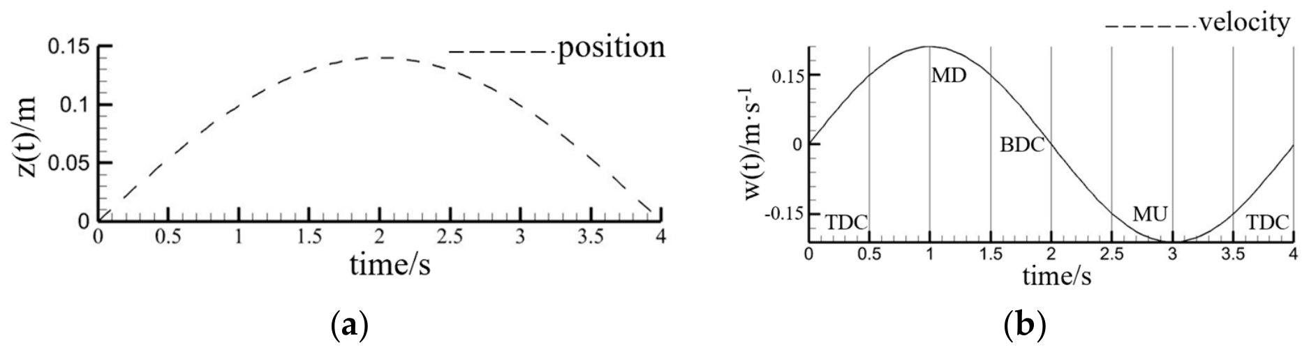
The stirring plate descends from the TDC to the BDC and then ascends back to the TDC, which constitutes one period T; under the present operating condition, the period is 4 s. Figure 3 shows the instantaneous position and velocity curves of the stirring plate within one cycle under the typical condition (A = 0.14 m, f = 0.25 Hz, L = 0.13 m). It can be seen that the velocity of the plate is zero at the TDC and the BDC and reaches its peak at the mid-point of the upward stroke (MU) and the mid-point of the downward stroke (MD), which is consistent with the motion law of the crank-and-connecting-rod mechanism.
Figure 3.
Instantaneous position and velocity of the reciprocating stirrer: (a) instantaneous position; (b) velocity.
2.2. Numerical Model
2.2.1. Governing Equations and Turbulence Model
The transient turbulent flow in the tank is described by the Reynolds-averaged Navier–Stokes (RANS) equations, which include the continuity equation and the momentum equation:
where ρ is the fluid density (kg/m3); ue and uj are the time-averaged velocity components (m/s); p is the time-averaged pressure (Pa); μ is the dynamic viscosity of the fluid (Pa·s); δje is the Kronecker delta; and −ρue′uj′ is the Reynolds stress term.
where μt is the turbulent viscosity (Pa·s) and k is the turbulent kinetic energy (m2/s2).
The flow regime in the tank is judged by the mean Reynolds number Rem, defined as
where is the mean velocity of the stirring plate (m/s) and D is the characteristic width of the stirring plate (m).
According to the calculation, the minimum mean Reynolds number under the present operating conditions is 2.46 × 10⁴, which is far greater than the critical value of 1000 for turbulent flow; therefore, the flow in the tank is fully developed turbulent flow. The standard k-ε turbulence model is adopted to close the Reynolds-averaged equations, and this model has good applicability in the simulation of reciprocating stirring flow fields [6]. Although the standard k-ε model is generally considered less accurate for flows with strong separation, severe pressure gradients, or unconfined vortices, in the present configuration the flow is confined within the baffled semi-circular tank at a moderate Reynolds number, and the separation and vortex regions are bounded by the tank walls and the baffle. Under these conditions, the standard k-ε model with standard wall functions provides a computationally economical and reasonably accurate description of the integral flow and mixing characteristics investigated here, as supported by the quantitative agreement between the simulated particle-uniformity trend and the experimental measurements reported in Section 4.
2.2.2. VOF Model
The Volume of Fluid (VOF) method is used to track the gas–liquid free surface in the tank, and the spatial distribution of each phase is determined by solving the volume-fraction transport equation. For the q-th phase, its volume fraction αo satisfies
and the volume fractions of all phases satisfy Σαo = 1. In this study, the gas and liquid phases share a single set of momentum equations, and the fluid properties are obtained by weighting the properties of each phase with its volume fraction.
2.2.3. DPM
The motion of the diamond particles in the stirring device is discrete; therefore, the Discrete Phase Model (DPM) is adopted to simulate the motion of the diamond particles. Based on the Eulerian-Lagrangian framework, this model treats the fluid as the continuous phase and the particles as the discrete phase, and is applicable to dilute liquid–solid systems with a particle volume fraction below 10%. The particle motion is governed by Newton’s second law:
where mp is the particle mass (kg); vp is the particle velocity vector (m/s); FD is the drag force; FB is the buoyancy force; FP is the pressure gradient force; FVM is the virtual mass force; FR is the inertial force of the rotating system; FS is the Saffman lift force; and FBA is the Basset force (N).
In the present study, the volume fraction of the diamond particles is far below 10%, and the particle size is small. Under such a dilute condition, particle–particle collisions and the resulting localized-concentration effects are negligible, and the localized concentration that may arise near the stirring plate or in the baffle clearance is governed mainly by the convective transport of the continuous phase. The DPM is therefore used with the particle–particle collisions and interactions neglected, and only the one-way coupling of the fluid on the particles is considered. It should be noted that, for more concentrated suspensions, particle–particle collisions and four-way coupling would need to be considered.
2.3. Mesh Generation and Independence Verification
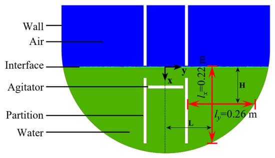
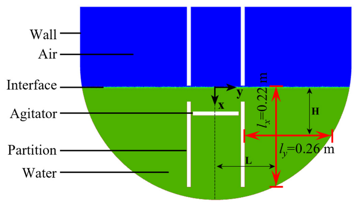
Because the cross-section of the mixing tank is identical along its length, the three-dimensional model is simplified to a two-dimensional computational domain to reduce the computational cost. An unstructured mesh is used to discretize the computational domain, as shown in Figure 4.
Figure 4.
Mesh generation and parameter settings.
As the outlet is located in this cross-section and has no thickness in the out-of-plane direction, the equivalent dissipative effects of the three-dimensional flow can be approximately incorporated into the two-dimensional model, which captures the dominant flow-field features with acceptable accuracy. This simplification neglects the end-wall effects and lateral vortex stretching at the two axial ends. The influence of the axial dead zones is equivalently represented by the near-wall boundary-layer thickness resolved in the two-dimensional mesh, which accounts for the momentum loss induced by the axial walls.
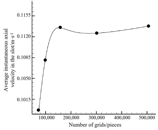
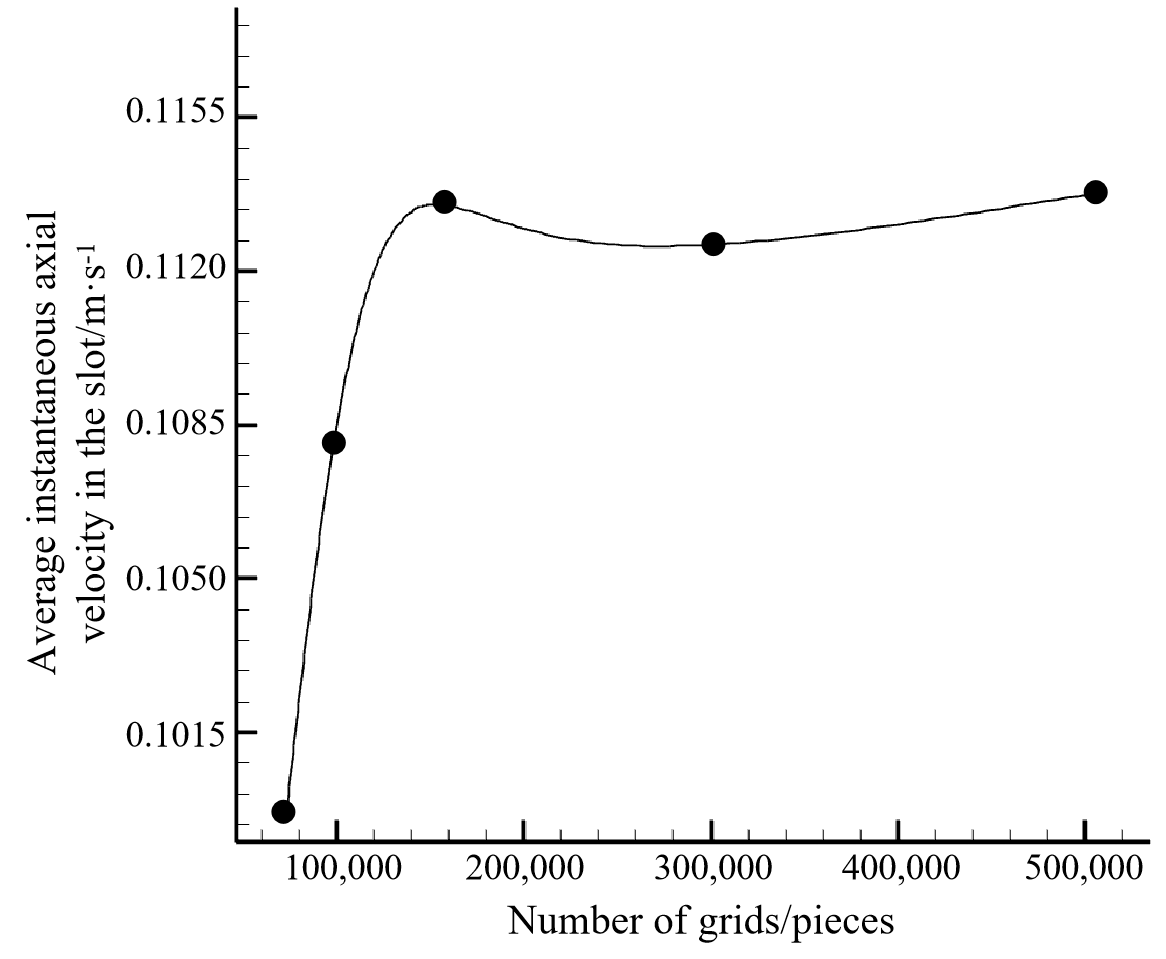
An unstructured triangular mesh was adopted, with local refinement in the baffle-clearance channel, near the stirring plate, and adjacent to the tank walls to resolve the clearance jet and the near-wall boundary layers. To eliminate the influence of the mesh density on the computational results, five characteristic mesh sizes of 1.00 mm, 1.25 mm, 1.50 mm, 1.75 mm, and 2.0 mm were selected for mesh independence verification, with the time-averaged axial velocity in the slot used as the monitoring indicator; the mesh independence verification results are shown in Figure 5. The results show that, when the mesh size is reduced from 1.50 mm to 1.25 mm, the relative deviation of the monitored velocity is less than 2%, satisfying the computational accuracy requirement. The characteristic mesh size of 1.50 mm was therefore adopted, with a total of 141,321 mesh cells.
Figure 5.
Mesh independence verification results.
The computational grid was generated with the meshing module of Fluent meshing 2020R2. An unstructured mesh consisting of triangular cells was adopted, with a characteristic surface mesh size of 1.5 mm and a growth rate of 1.2 in the transition region. To resolve the near-wall velocity gradients and the clearance jet, a boundary-layer inflation treatment was applied adjacent to the tank walls and around the stirring plate, with a first-layer height of 0.2 mm, five boundary layers, and a layer growth rate of 1.2.
The grid convergence index, abbreviated as GCI, was further evaluated to quantify the discretization uncertainty of the mesh-independence study, following the procedure recommended by Celik et al. [27]. The apparent order of convergence was estimated from three consecutive grid levels by Richardson extrapolation, and the GCI was computed with a safety factor Fs of 1.25. Taking the 1.25 mm and 1.50 mm meshes as the reference pair, with a refinement ratio r of 1.2, the relative deviation of the monitored time-averaged axial velocity was approximately 1.06%, giving a GCI of about 1.8%. Since the adopted 1.50 mm mesh deviates from the finer 1.25 mm mesh by only about 1.06%, the discretization uncertainty of the adopted mesh remains of the same order and well below the commonly accepted threshold of 5%, confirming that the adopted mesh provides a grid-independent solution.
The monitored velocity was obtained by averaging the instantaneous axial velocity over a complete reciprocating cycle after the flow field reached a quasi-steady state, so that the time-dependent variation in the flow is inherently reflected in the comparison. In addition, the dynamic-mesh implementation in the Fluent solver satisfies the geometric conservation law, and the mass imbalance remained negligible throughout the transient calculation.
2.4. Numerical Simulation Settings
The transient numerical calculation was performed with the Fluent 2020 R2 solver (ANSYS Inc., Canonsburg, PA, USA). A UDF program was compiled using the DEFINE_CG_MOTION macro to load the instantaneous velocity of the stirring plate onto the dynamic mesh region, thereby enabling the dynamic simulation of the reciprocating motion. The multiphase model was set as the VOF model, and the DPM was added. The transient time step was 0.001 s, with 20 iterations per step. The pressure-based solver was used to iteratively solve the conservation equations, and the SIMPLE algorithm was adopted for the pressure–velocity coupling, with a first-order upwind scheme. The standard wall function was used for the near-wall treatment, and the near-wall y+ values were maintained within approximately 30–300. The convergence criteria were set as residuals below 1 × 10⁻³ for continuity and below 1 × 10⁻⁴ for the momentum and turbulence equations. In the dynamic-mesh scheme, spring-based smoothing combined with local remeshing was adopted to accommodate the displacement of the stirring plate. At the initial instant, the fluid domain was patched, and the stirring plate was located at the TDC position.
The intrinsic parameters of the materials were determined experimentally to ensure the reliability of the simulation. The liquid phase was a nickel sulfamate plating bath with a density of 1365 kg/m3. The particle size distribution of the diamond particles was measured by the wet method using an OMEC LS-POP laser particle size analyzer (OMEC, Zhuhai, China); the specific parameters are listed in Table 1. The particle density was determined by the water displacement method to be 5200 kg/m3.
Table 1.
Particle size distribution of diamond particles.
During the calculation, the first two reciprocating cycles were used for the flow-field development to eliminate the influence of the initial condition, and the flow-field data were collected for analysis starting from the third cycle.
2.5. Evaluation Indicators of Mixing Performance
To quantitatively evaluate the flow and mixing performance in the mixing tank, evaluation indicators were established at two levels, namely the flow characteristics and the particle uniformity.
2.5.1. Flow-Field Indicators
The area-weighted instantaneous mean velocity ū(t), the relative standard deviation vRSD, and the dimensionless velocity v* are adopted as the evaluation indicators.
The area-weighted instantaneous mean velocity of the entire fluid domain in the tank is defined as
where dA′ is the area of a mesh face (m2) and A′ is the total area of the mesh faces (m2).
To eliminate the influence of the operating parameters on the flow-pattern analysis, the dimensionless velocity v* is introduced, which is defined as the ratio of the local velocity to the global maximum velocity:
The relative standard deviation vRSD is used to characterize the uniformity of the velocity distribution, and its calculation formula is
where n is the total number of mesh faces; vRSD(t) is the relative standard deviation of the velocity distribution at time t, and a smaller value indicates a more uniform velocity distribution.
2.5.2. Particle Uniformity Indicator
The relative standard deviation of the particle mass fraction, PRSD, is adopted as the core evaluation indicator of the particle mixing uniformity, and it is used for both the post-processing of the numerical simulation and the processing of the experimental data. The calculation formulas are
where is the particle mass fraction at the i-th sampling point (%) and n is the total number of sampling points. A smaller PRSD indicates a more uniform particle distribution.
The uniformity of the fluid velocity field is the dynamic basis for the uniform dispersion of the particles: the more uniform the velocity distribution, the more frequently the vortices are renewed, and the better the diffusion of the particles entrained by the fluid; therefore, vRSD and PRSD are intrinsically positively correlated. Through this correlation, the velocity-field analysis of the numerical simulation and the particle-concentration measurement of the experiments are unified within the same evaluation framework.
3. Results and Discussion
3.1. Transient Flow-Field Evolution Characteristics of the Reciprocating Mixing Tank
3.1.1. Dynamic Evolution of Vortex Structures Within One Stirring Cycle
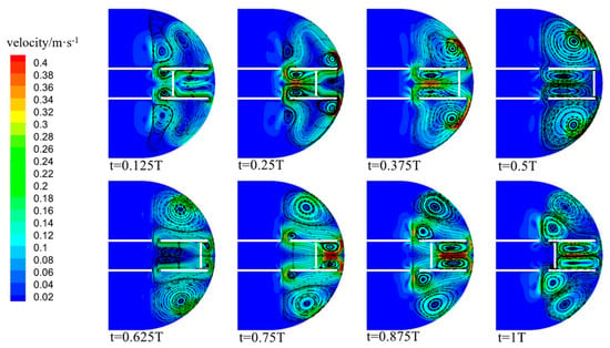
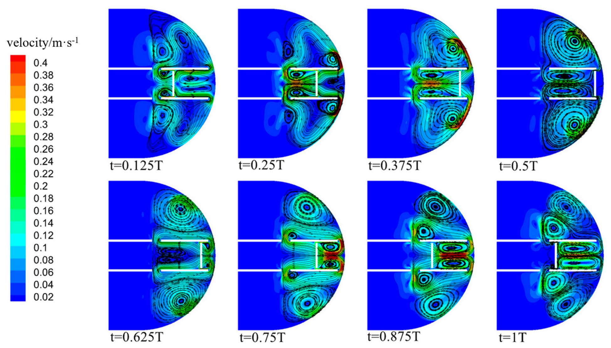
The instantaneous velocity contours at different instants within one stirring cycle under the condition of f = 0.25 Hz and A = 0.14 m are shown in Figure 6. Driven by the reciprocating motion of the stirring plate, three typical dynamic vortex regions are formed in the tank, located above the stirring plate, below the stirring plate, and outside the baffle, respectively. The size, position, and intensity of the vortices change periodically with the motion phase of the stirring plate.
Figure 6.
Instantaneous velocity fields at different times (f = 0.25 Hz, A = 0.14 m).
When the stirring plate moves downward from the TDC position (t = 0.125T–0.5T), it pushes the fluid below it upward through the baffle clearance, forming a high-speed jet near the baffle. At t = 0.125T, two small-scale vortices exist above and below the stirring plate, respectively, and two separated vortices exist outside the baffle. As the plate continues to move downward (t = 0.25T), the vortex above the plate gradually expands while the vortex below the plate gradually shrinks; a new vortex is generated at the lower part of the baffle, and the two vortices near the side wall merge into one near the liquid surface. At t = 0.375T, the total number of vortices decreases from 8 to 4: the vortices below the plate and above the liquid surface disappear, the vortex above the plate continues to grow, and the side-wall vortex moves upward along the wall. When the stirring plate reaches the BDC (t = 0.5T), its velocity drops to zero and the overall flow velocity in the tank decreases; however, the vortex in the circular-arc region outside the baffle reaches its maximum size, and the velocity there is higher than that in the regions above and below the plate.
When the stirring plate moves upward from the BDC (t = 0.625T–1T), the flow-field evolution process is essentially symmetric and opposite to that during the downward stroke. The plate drives the fluid above it upward, and the fluid returns downward through the baffle clearance; the vortex below the plate gradually develops and grows, while the vortex above the plate gradually weakens, eventually returning to the initial state and completing one cycle.
Unlike conventional impeller-based rotary stirring, which readily produces a central vortex dead zone [13] and can cause impact damage to particle morphology [14,15], the reciprocating flat plate generates multiple dynamic vortices covering the tank without a stagnant central region, so that the particles are continuously redistributed and uniformly dispersed; this behaviour is consistent with the mixing-efficiency improvement induced by reciprocating motion reported by Hirata et al. [19].
The baffle divides the mixing tank into a main flow region and a side flow region. The reciprocating motion of the stirring plate creates a pressure difference between the two regions, which drives the fluid to flow at high speed through the clearance and form a jet. The jet entrains the surrounding fluid and thereby induces large-scale vortices, which is the core mechanism by which reciprocating stirring achieves efficient mixing. The periodic generation, development, merging, and dissipation of the vortices continuously renew the distribution of the fluid elements in the tank, effectively avoiding the formation of local dead zones.
3.1.2. Spatial Distribution Characteristics of the Velocity Field
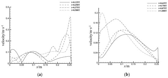
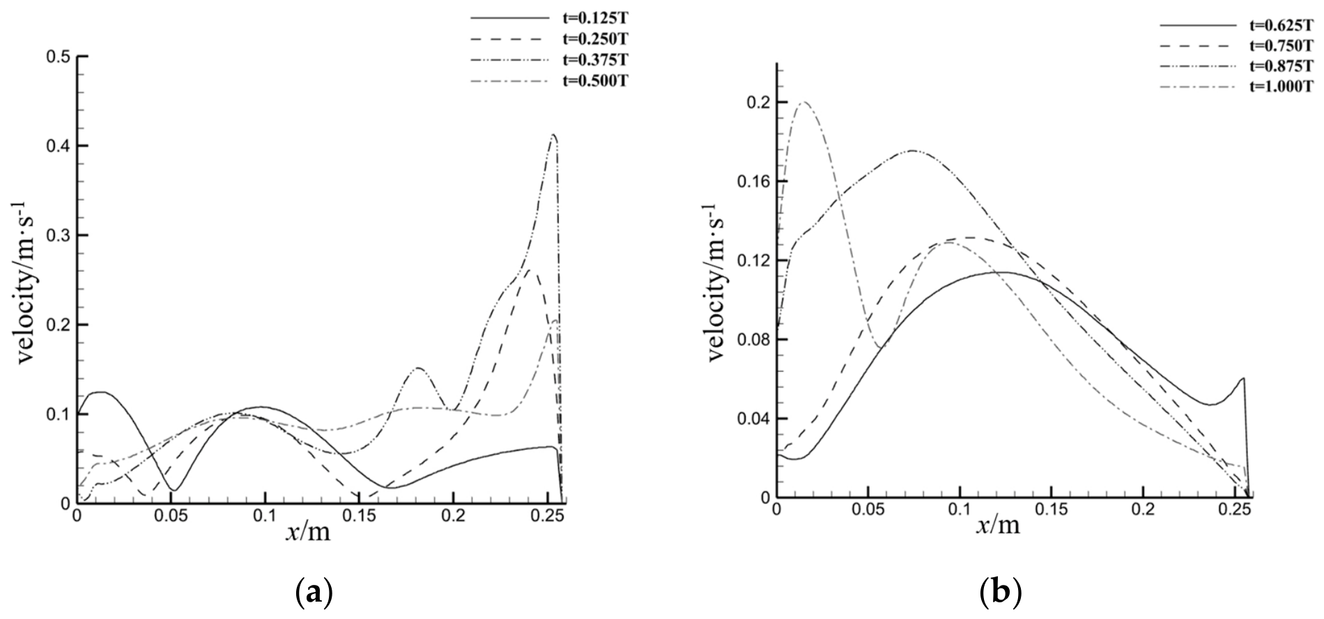
The axial velocity distribution profiles of the fluid at different motion phases (monitoring line L = 0.15 m, i.e., 0.15 m from the x-axis) are shown in Figure 7. It can be seen that the axial velocity distribution during the downward stroke is opposite to that during the upward stroke.
Figure 7.
Axial velocity distributions at different instants (f = 0.25 Hz, A = 0.14 m, L = 0.15 m). (a) Downward stroke; (b) Upward stroke.
During the downward stroke (t = 0.125T–0.5T), the velocity near the liquid surface fluctuates appreciably only at t = 0.125T, showing an oscillatory feature. The axial velocity in the circular-arc region at the tank bottom first increases and then decreases, reaching a peak of 0.43 m/s at t = 0.375T. During the upward stroke (t = 0.625T–1T), the velocity fluctuation near the liquid surface is largest at t = 1T. At the position of x = 0.05 m, the axial velocity first increases and then decreases; at x = 0.10 m, the velocity differences among different instants are small; and at x = 0.15 m, the velocity gradually decreases with time. It should be noted that, under this operating condition, the maximum velocity of the stirring plate itself is only 0.22 m/s, whereas the maximum axial velocity of the fluid in the tank can reach 0.43 m/s, i.e., 1.95 times the maximum velocity of the stirring plate. When the stirring plate is located at the MD position, the velocity peaks above and below the plate are 1.28 times and 0.59 times the maximum velocity of the stirring plate, respectively.
This pronounced velocity-amplification effect arises from two mechanisms. First, the throttling effect of the baffle clearance: when the fluid passes through the narrow clearance, the flow area decreases sharply, and, according to the continuity equation, the flow velocity increases markedly. Second, the entrainment effect of the vortices: the large-scale vortices carry the surrounding fluid into joint motion, further amplifying the local flow velocity.
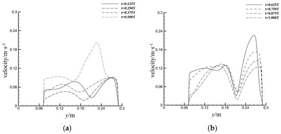
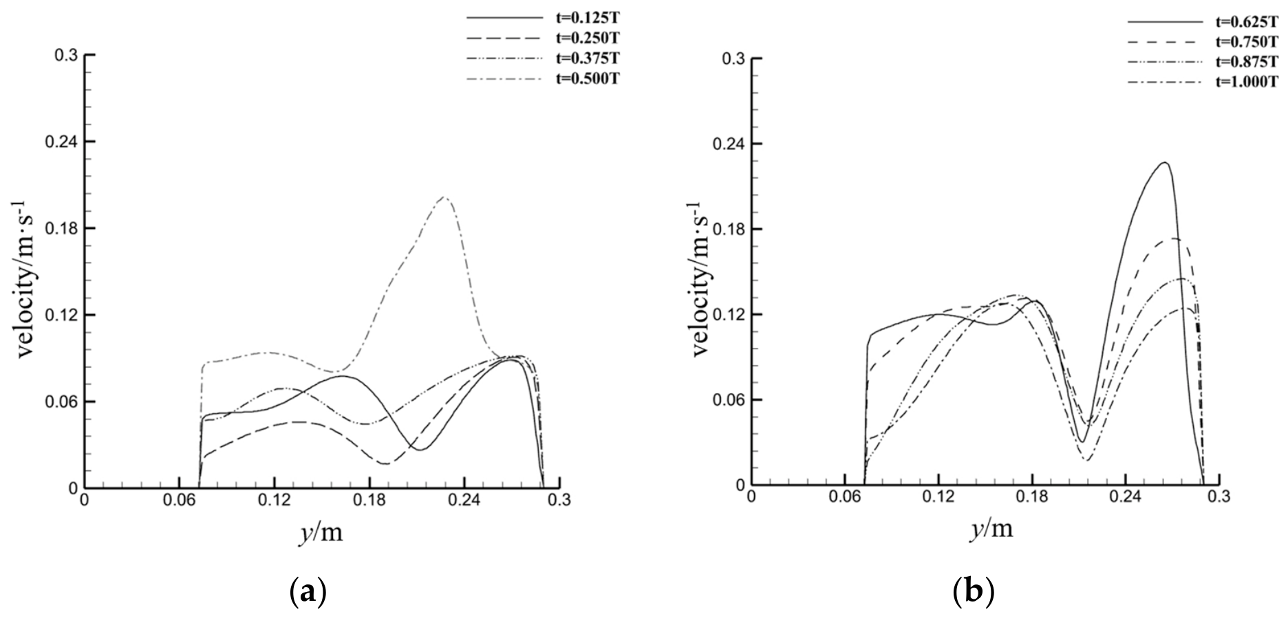
The radial velocity distribution profiles of the fluid at different motion phases (monitoring line H = 0.08 m, i.e., 0.08 m from the y-axis) are shown in Figure 8. During the stage of t = 0.125T–0.375T, the radial velocity is generally small, fluctuating in the range of 0.02–0.1 m/s, without obvious variation with the phase. At t = 0.5T, affected by the rising large-scale vortex outside the baffle, the radial velocity increases significantly, and the velocity profile exhibits an abrupt change, reaching a peak of 0.21 m/s within the range of y = 0.2–0.25 m, which is comparable to the maximum velocity of the stirring plate.
Figure 8.
Radial velocity distributions at different instants (f = 0.25 Hz, A = 0.14 m, H = 0.08 m). (a) Downward stroke; (b) Upward stroke.
When the stirring plate moves upward from the BDC (t = 0.625T–1T), the radial velocity distribution exhibits a regular double-peak profile, with a velocity trough in the range of y = 0.2–0.25 m and one velocity peak on each side, which corresponds to the symmetric distribution structure of the vortices.
3.1.3. Turbulent Kinetic Energy Distribution and Mixing Intensity
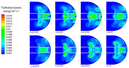
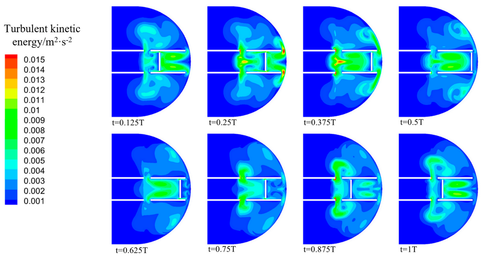
The turbulent kinetic energy is a core indicator for measuring the turbulent mixing intensity: the higher its value, the stronger the fluid fluctuation and diffusion. The turbulent kinetic energy contours at different instants within one cycle are shown in Figure 9. The results show that the turbulent kinetic energy is relatively high in most regions of the tank, and the high-value regions are mainly concentrated near the surface of the stirring plate and in the baffle clearance, because the shear action of the stirring plate and the entrainment effect of the clearance jet generate intense fluid fluctuations. These turbulent characteristics are in agreement with the turbulent flow features induced by a reciprocating disk in a cylindrical vessel reported by Komoda et al. [20].
Figure 9.
Turbulent kinetic energy k (f = 0.25 Hz, A = 0.14 m).
During the downward stroke of the stirring plate, the turbulence intensity above the plate gradually increases. At t = 0.25T, the turbulent kinetic energy in the circular-arc region at the tank bottom and in the baffle region reaches its maximum value. At t = 0.375T, the turbulent kinetic energy near the liquid surface reaches a peak. The periodic evolution of the high-turbulent-kinetic-energy regions can effectively enhance the mass transfer and particle suspension in the tank, ensuring mixing uniformity.
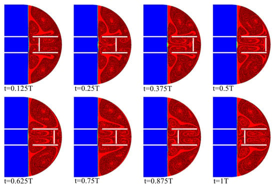
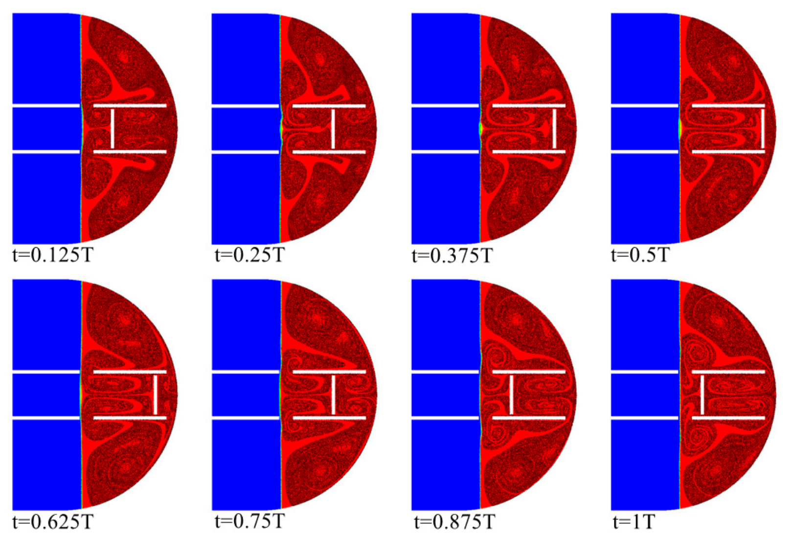
The distribution state of the particles in the tank is shown in Figure 10. The particle trajectories are basically consistent with the fluid streamlines, and the particles perform periodic cyclic motion carried by the flow field. The number and size of the particle vortices change dynamically with the motion phase of the stirring plate, in close agreement with the evolution of the fluid vortices, indicating that the flow structure of the fluid phase directly determines the dispersion state of the particles. This result verifies the correlation mechanism between the flow-field characteristics and the particle distribution: the periodic evolution of the fluid vortices drives the continuous redistribution of the particles, which is the intrinsic reason for achieving uniform particle mixing.
Figure 10.
Distribution of diamond particles in the gas–liquid two-phase flow field (f = 0.25 Hz, A = 0.14 m). Blue represents the gas phase, red represents the liquid phase, and white represents the stirring plate.
3.2. Influence of Reciprocating Frequency on Flow and Mixing Performance
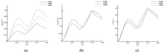
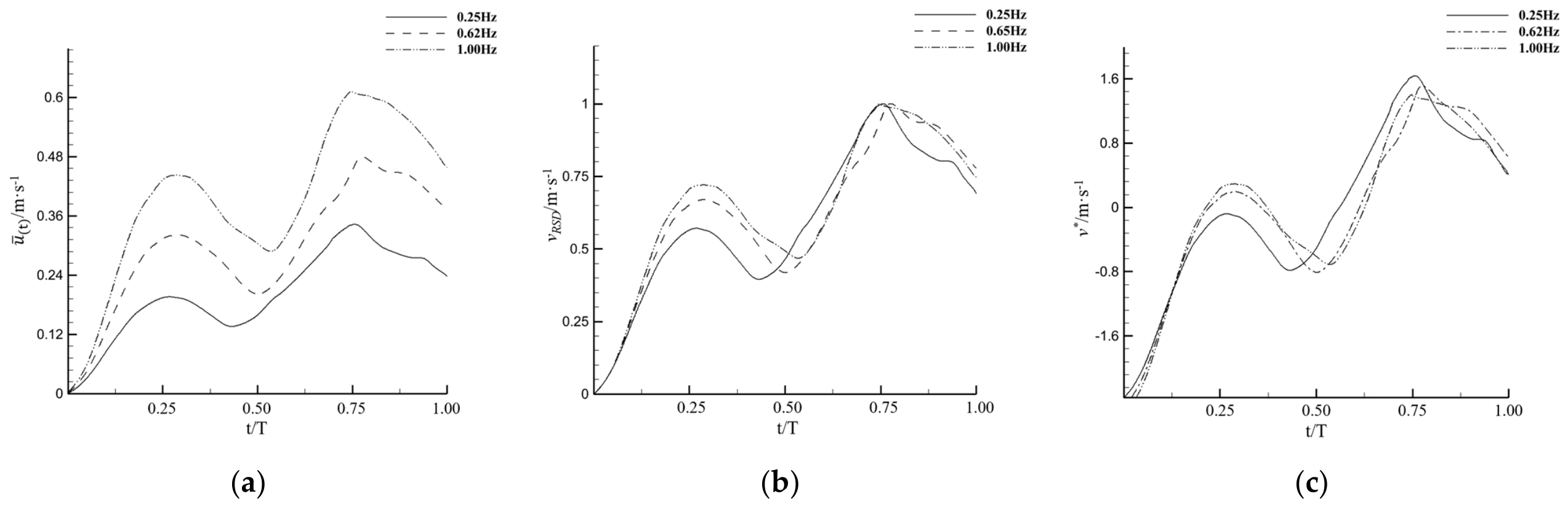
To investigate the influence of the reciprocating frequency on the mixing performance, the liquid flow characteristics in the tank were compared at three reciprocating frequencies, namely 0.25 Hz, 0.62 Hz, and 1.00 Hz; the results are shown in Figure 11.
Figure 11.
Instantaneous mean velocity, dimensionless velocity, and relative standard deviation at different reciprocating frequencies: (a) instantaneous mean velocity; (b) instantaneous relative standard deviation of the velocity distribution; (c) dimensionless mean velocity.
3.2.1. Effect on the Instantaneous Mean Velocity
The instantaneous variation curves of the area-weighted mean velocity in the tank at different frequencies are shown in Figure 11a. Affected by the fluid inertia, the variation in the mean fluid velocity lags slightly behind the motion of the stirring plate. The stirring plate reaches its velocity peak at the MU position, whereas the peak of the mean fluid velocity appears shortly after the plate passes the MU position.
As the reciprocating frequency increases, the overall level of the instantaneous mean velocity in the tank rises significantly, and the frequency of the velocity fluctuation increases correspondingly. This is because, at a higher frequency, the work done by the stirring plate on the fluid per unit time increases, so the fluid obtains more kinetic energy and the overall flow velocity rises. From the viewpoint of the energy input, the power of the work done by the stirring plate on the fluid is proportional to the square of the frequency; therefore, increasing the frequency has a pronounced effect on raising the flow velocity.
3.2.2. Effect on the Uniformity of the Velocity Distribution
The instantaneous relative standard deviation curves of the velocity distribution at different frequencies are shown in Figure 11b. The uniformity of the velocity distribution varies periodically with the motion phase, which is consistent with the evolution period of the flow-field vortices. As the reciprocating frequency increases, the overall level of the instantaneous vRSD decreases slightly, indicating that a higher frequency can improve the uniformity of the velocity distribution to a certain extent.
The reason is that, at a high frequency, the number of vortex renewals per unit time increases, the fluid fluctuation is more intense, and the momentum transfer is more complete, so that the velocity differences among different regions are smoothed out more quickly, resulting in a more uniform velocity distribution. This trend is consistent with the variation in the particle mixing uniformity, which provides a basis for optimizing the mixing effect by adjusting the frequency.
3.2.3. Dimensionless Velocity and Flow-Pattern Similarity
The dimensionless mean velocity variation curves at different frequencies are shown in Figure 11c. Although the absolute velocity increases with increasing frequency, the variation in the dimensionless mean velocity is almost exactly the same, and the relative positions of the peaks and troughs remain basically unchanged.
According to the flow similarity principle, under an unchanged geometric structure, changing the reciprocating frequency only changes the time scale of the flow without changing the spatial flow-pattern structure; therefore, the dimensionless velocity distribution remains consistent. This also implies that, within a certain range, adjusting the reciprocating frequency can regulate the mixing intensity by changing the flow velocity without changing the mixing mechanism, which provides theoretical guidance for the optimization of the process parameters.
4. Experimental Verification of Mixing Uniformity
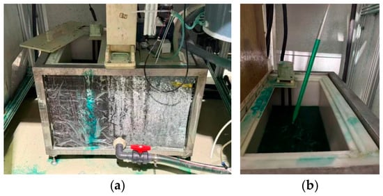
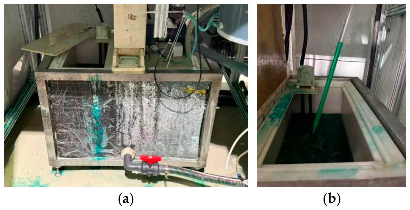
To verify the conclusions of the numerical simulation and to evaluate the actual particle mixing effect of the reciprocating stirring device, an experimental platform was built for the mixing uniformity test; the experimental apparatus is shown in Figure 12. The main body of the apparatus consists of a semi-circular liquid storage tank and a reciprocating stirring mechanism, with structural parameters consistent with the numerical model: the radius of the liquid storage tank is R = 0.34 m, and the stirring plate dimensions are 0.4 m × 0.116 m × 0.01 m; polypropylene was adopted to reduce the influence of the motion inertia on the measurements. In the experiments, the clearance between the bottom of the stirring plate and the tank bottom was set to h = 0.215R, and the liquid level height in the tank was H = 0.8R. A nickel sulfamate plating bath was used as the liquid phase, and the diamond particles used in the experiments had the same properties as those in the simulation, with the particle size distribution shown in Table 1.
Figure 12.
Experimental apparatus for the mixing uniformity verification of the reciprocating stirring device: (a) experimental apparatus; (b) diamond particle suspension (plating bath) after stirring.
The dropper sampling method was adopted to determine the spatial distribution uniformity of the particles, and the experimental procedure followed the principles of sampling, detection, and statistical analysis. First, after the stirring ran stably, 10 sampling points were selected at different heights (upper, middle, and lower) in the tank, and a 100 mL suspension was quickly collected at each sampling point with a custom-made sampling tube. The mass of the diamond particles in each sample was determined by the oven-drying gravimetric method, and the mass fraction was calculated. The mean , the standard deviation s, and the relative standard deviation PRSD of the sample mass fractions were calculated, with PRSD adopted as the evaluation indicator of the mixing uniformity; a smaller PRSD indicates better uniformity.
The calculation formulas for the relevant statistics are given in Equations (13)–(15). Dynamic rapid sampling was adopted in the experiments to shorten the sampling time as much as possible and to avoid the measurement errors caused by particle settling. Referring to the general standard of the chemical industry, the qualified limit for the particle mixing uniformity is PRSD ≤ 5.0%.
Under the process condition of 0.5 Hz, the particle mass fraction measurement results at the 10 sampling points are listed in Table 2. According to the calculation, the mean particle mass fraction is 0.279%, the standard deviation s is 0.0129%, and the relative standard deviation PRSD is 4.62%, which is lower than the industrial limit of 5.0%.
Table 2.
Diamond particle mass fractions (%).
This quantified uniformity performance demonstrates that the baffled flat-plate reciprocating stirring device satisfies the dispersion requirement of the diamond-wire sand-setting process, corroborating the superior mixing performance of reciprocating over rotary agitation reported by Kordas et al. [21].
The experimental results show that the reciprocating stirring device can achieve the uniform dispersion of the diamond particles in the plating bath and satisfies the uniformity requirements of the sand-setting process. Combined with the numerical simulation results, the 0.5 Hz condition lies between the simulated 0.25 Hz and 0.62 Hz; according to the interpolation analysis of the frequency influence law, the tank exhibits a relatively high flow velocity and a good velocity-distribution uniformity under this condition. The periodically evolving vortices continuously renew the particle distribution and prevent particle settling and agglomeration, which is the fundamental reason for the good mixing effect. The uniformity trend obtained in the experiments is consistent with the uniformity characteristics of the velocity distribution in the simulation, which verifies the reliability of the numerical model in this study.
It should be acknowledged that the present experimental verification is based on the integral mixing-uniformity indicator PRSD rather than on direct measurements of the flow field, for two reasons. First, the flow-field indicators predicted by the CFD model, namely the velocity distribution, vortex structure, and turbulent kinetic energy, and the experimentally measured particle uniformity are linked through the correlation established in Section 2.5.2; the agreement between the simulated uniformity trend and the experimental PRSD therefore provides an indirect but meaningful validation of the model’s predictive capability. Second, direct measurement of the instantaneous velocity field inside the semi-circular tank is difficult because of the limited optical access and the presence of the baffle and the moving plate.
5. Conclusions
Aiming at the process requirements of diamond wire electroplating sand-setting, this study investigated the flow and mixing characteristics of a baffled semi-circular reciprocating stirring device using the VOF–DPM coupling method. The main conclusions are as follows:
- (1)
- Under the two-dimensional model, three typical dynamic vortex regions are predicted in the baffled semi-circular reciprocating mixing tank, located above the stirring plate, below the stirring plate, and outside the baffle. The size and position of the vortices evolve periodically with the motion phase of the stirring plate: during the downward stroke, the total number of vortices gradually decreases from 8 to 4, and the side-wall vortex above the plate eventually reaches its maximum size; during the upward stroke, the flow-field evolution is symmetrically opposite. The throttling effect of the baffle clearance and the jet entrainment are the core mechanisms of the vortex generation and enhancement.
- (2)
- The reciprocating motion of the flat plate has a pronounced velocity-amplification effect on the fluid. Under the condition of A = 0.14 m and f = 0.25 Hz, the maximum velocity of the stirring plate itself is 0.22 m/s, whereas the maximum axial velocity in the tank reaches 0.43 m/s, which is 1.95 times the velocity of the stirring plate. The maximum radial velocity is 0.21 m/s, which is comparable to the maximum velocity of the stirring plate. Both the axial and radial velocity distributions exhibit symmetric and opposite patterns with the direction of the motion.
- (3)
- The reciprocating frequency significantly affects the absolute velocity of the flow in the tank but does not change the basic flow-pattern structure. As the frequency increases, the mean velocity in the tank increases overall, the uniformity of the velocity distribution improves slightly, and the dimensionless velocity characteristics remain basically consistent, which conforms to the flow similarity principle.
- (4)
- Under the process condition of 0.5 Hz, the relative standard deviation of the diamond particle mass fraction, PRSD, is 4.62%, which is lower than the industrial uniformity limit of 5%, demonstrating that the device can satisfy the dispersion requirements of the diamond particles.
Author Contributions
Conceptualization, T.G. and J.L. (Jiahao Liu); methodology, J.L. (Jiahao Liu) and T.G.; software, Z.L.; validation, X.Z., J.L. (Jingang Liu) and T.G.; formal analysis, X.Z. and M.Z.; investigation, J.H. and M.Z.; resources, T.G. and M.Z.; data curation, J.L. (Jingang Liu) and Z.L.; writing—original draft preparation, T.G. and J.H.; writing—review and editing, J.L. (Jiahao Liu) and T.G.; visualization, T.G., J.L. (Jiahao Liu) and J.H.; supervision, T.G. and J.L. (Jingang Liu); project administration, T.G. and J.L. (Jingang Liu); funding acquisition, T.G. All authors have read and agreed to the published version of the manuscript.
Funding
This research was funded by Science and Technology Plan Project of Hunan Provincial Administration for Market Regulation (Grant No. 2024KJJH23); Natural Science Foundation of Hunan Province (Grant No. 2025JJ80215).
Data Availability Statement
The original contributions presented in this study are included in the article. Further inquiries can be directed to the corresponding author.
Acknowledgments
During the preparation of this manuscript/study, the authors used DeepSeek V4 for the purposes of translation and proofreading. The authors have reviewed and edited the output and take full responsibility for the content of this publication.
Conflicts of Interest
Authors Tao Gong, Jiahao Liu, Ming Zhao, Zhou, Zhuangzhi Li and Junhao Hu were employed by the company Hunan Yujing Machine Co., Ltd. The remaining authors declare that the research was conducted in the absence of any commercial or financial relationships that could be construed as potential conflicts of interest.
Abbreviations
The following abbreviations are used in this manuscript:
| CFD | computational fluid dynamics |
References
- Sefene, E.M.; Chen, C.A.; Tsai, Y. A comprehensive review of diamond wire sawing process for single-crystal hard and brittle materials. J. Manuf. Process 2024, 131, 1466–1497. [Google Scholar] [CrossRef] [Scilit]
- Zhang, N.; Li, H.; Gao, Y. The state of the art of wire sawing-based hybrid cutting technology: A review. Int. J. Adv. Manuf. Technol. 2024, 133, 2001–2030. [Google Scholar] [CrossRef] [Scilit]
- Li, A.; Hu, S.; Zhou, Y.; Wang, H.; Zhang, Z.; Ming, W. Recent advances in precision diamond wire sawing monocrystalline silicon. Micromachines 2023, 14, 1512. [Google Scholar] [CrossRef] [Scilit] [PubMed]
- Li, J.; Lin, J.; Li, D.; Cheng, J. Flow-field-coupled thickness prediction and process optimization of diamond–nickel composite electroformed coatings for ultra-thin dicing blades. Precis. Eng. 2026, 102, 855–878. [Google Scholar] [CrossRef] [Scilit]
- Weijs, J.H.; Bartolo, D. Mixing by unstirring: Hyperuniform dispersion of interacting particles upon chaotic advection. Phys. Rev. Lett. 2017, 119, 48002. [Google Scholar] [CrossRef] [Scilit] [PubMed]
- Mehta, V.R.; Sutaria, M.P. Investigation on the effect of stirring process parameters on the dispersion of SiC particles inside melting crucible. Met. Mater.-Int. 2021, 27, 2989–3002. [Google Scholar] [CrossRef] [Scilit]
- Su, S.; Zang, J.; Zhou, Y.; Liu, W.; Zhang, X.; Zhao, M.; Wang, Y. Efficient manufacture of high-performance electroplated diamond wires utilizing Cr-coated diamond micro-powder. Mater. Sci. Semicond. Process 2024, 179, 108511. [Google Scholar] [CrossRef] [Scilit]
- Huang, C.A.; Shen, C.H.; Huang, W.Z.; Lo, J.S.; Lai, P.L. Grinding performance of electroplated diamond tools strengthened with Cr-C deposit using D-150 diamond particles. Int. J. Adv. Manuf. Technol. 2022, 121, 4549–4558. [Google Scholar] [CrossRef] [Scilit]
- Kim, D.; Kim, H.; Lee, S.; Lee, T.; Jeong, H. Characterization of diamond wire-cutting performance for lifetime estimation and process optimization. J. Mech. Sci. Technol. 2016, 30, 847–852. [Google Scholar] [CrossRef] [Scilit]
- Huang, C.A.; Yang, S.W.; Shen, C.H.; Cheng, K.C.; Wang, H.; Lai, P.L. Fabrication and evaluation of electroplated Ni–diamond and Ni–B–diamond milling tools with a high density of diamond particles. Int. J. Adv. Manuf. Technol. 2019, 104, 2981–2989. [Google Scholar] [CrossRef] [Scilit]
- Huda, N.; Bisht, A.; Moreau, E.; Corbin, S.; Rabkin, E.; Gerlich, A.P. Fabrication of copper–diamond composite by friction stir processing. J. Mater. Sci. 2023, 58, 4184–4198. [Google Scholar] [CrossRef] [Scilit]
- Huang, C.A.; Shen, C.H.; Lee, C.J.; Wang, H.; Lai, P.L. Grinding performances of electroplated Ni–B-diamond tools prepared through composite electroplating with intermittent stirring. Int. J. Adv. Manuf. Technol. 2023, 124, 1891–1903. [Google Scholar] [CrossRef] [Scilit]
- Busciglio, A.; Montante, G.; Kracík, T.; Moucha, T.; Paglianti, A. Rotary sloshing induced by impeller action in unbaffled stirred vessels. Chem. Eng. J. 2017, 317, 433–443. [Google Scholar] [CrossRef] [Scilit]
- Hoang, T.; Lee, H. Rotational disruption of dust grains by mechanical torques for high-velocity gas–Grain collisions. Astrophys. J. 2020, 896, 144. [Google Scholar] [CrossRef] [Scilit]
- Tu, J.; Wang, X.; Liu, B. Fragmentation behavior of diamond particles with different particle size and ratio under high pressure compaction. Ceram. Int. 2024, 50, 36145–36155. [Google Scholar] [CrossRef] [Scilit]
- Toister, R.; Khrapach, A. Computer modelling of the flow structure in a combined mixer for aqueous suspensions with solid and gas phases. Acad. J. Ind. Mach. Build. Civ. Eng. 2024, 2, 66–72. [Google Scholar] [CrossRef] [Scilit]
- Li, L.; Xiang, K.; Xiang, B. Numerical simulation of transient power consumption characteristics in an unbaffled stirred tank. Chem. Pap. 2020, 74, 2849–2859. [Google Scholar] [CrossRef] [Scilit]
- Wójtowicz, R. Flow pattern and power consumption in a vibromixer. Chem. Eng. Sci. 2017, 172, 622–635. [Google Scholar] [CrossRef] [Scilit]
- Kordas, M.; Story, G.; Konopacki, M.; Rakoczy, R. Study of mixing time in a liquid vessel with rotating and reciprocating agitator. Ind. Eng. Chem. Res. 2013, 52, 13818–13828. [Google Scholar] [CrossRef] [Scilit]
- Hirata, Y.; Dote, T.; Yoshioka, T.; Komoda, Y.; Inoue, Y. Performance of chaotic mixing caused by reciprocating a disk in a cylindrical vessel. Chem. Eng. Res. Des. 2007, 85, 576–582. [Google Scholar] [CrossRef] [Scilit]
- Komoda, Y.; Inoue, Y.; Hirata, Y. Characteristics of turbulent flow induced by reciprocating disk in cylindrical vessel. J. Chem. Eng. Jpn. 2001, 34, 929–935. [Google Scholar] [CrossRef] [Scilit]
- Fan, M.; Xu, J.; Sun, H.; Wang, S.; Zhang, X.; Wang, H.; Yin, W. Enhancement of chaotic mixing performance in laminar flow with reciprocating and rotating coupled agitator. Chem. Eng. Sci. 2023, 280, 118988. [Google Scholar] [CrossRef] [Scilit]
- Li, B.; Wang, X.; Ding, S.; Li, B.; Wang, W. Coupled VOF–DPM numerical simulation of pressure-swirl sprays with an improved transition criterion. Chem. Eng. Sci. 2027, 338, 124817. [Google Scholar] [CrossRef] [Scilit]
- Jin, W.; Xiao, J.; Ren, H.; Li, C.; Zheng, Q.; Tong, Z. Three-dimensional simulation of impinging jet atomization of soft mist inhalers using the hybrid VOF-DPM model. Powder Technol. 2022, 407, 117622. [Google Scholar] [CrossRef] [Scilit]
- Liu, S.; Zhu, X.; Lu, X.; Li, M.; Chen, X.; Qi, G.; Huo, W. Optimization and scaled validation research on impellers for aerated concrete mixing. J. Phys. Conf. Ser. 2026, 3296, 12007. [Google Scholar] [CrossRef] [Scilit]
- Chen, S.; Zhang, Y.; Wu, Z.; Fang, G.; Chen, Y.; Duan, J. Near-nozzle atomization characteristics in air-assisted spraying: Integrated VOF-DPM modeling and experimental validation. Coatings 2025, 15, 939. [Google Scholar] [CrossRef] [Scilit]
- Celik, I.B.; Ghia, U.; Roache, P.J.; Freitas, C.J. Procedure for estimation and reporting of uncertainty due to discretization in CFD applications. J. Fluids Eng. 2008, 130, 078001. [Google Scholar] [CrossRef] [Scilit]

Disclaimer/Publisher’s Note: The statements, opinions and data contained in all publications are solely those of the individual author(s) and contributor(s) and not of MDPI and/or the editor(s). MDPI and/or the editor(s) disclaim responsibility for any injury to people or property resulting from any ideas, methods, instructions or products referred to in the content. |
© 2026 by the authors. Licensee MDPI, Basel, Switzerland. This article is an open access article distributed under the terms and conditions of the Creative Commons Attribution (CC BY) license.