


Abstract
Progressive wear of the cutting structure degrades the performance of polycrystalline diamond compact (PDC) drill bits during deep and ultradeep drilling. Current designs primarily delay wear through improved material wear resistance and structural optimization, but provide limited capability for active downhole restoration after wear. This study proposes a rotary self-renewing PDC drill bit driven by drilling-fluid pressure through a worm gear transmission. The design allows active renewal of the cutting structure downhole. The overall bit structure was developed around four modules for pressure actuation, motion conversion and transmission, cutting-structure renewal, and position limiting. Kinematic and dynamic models were established to assess the required driving force and transmission characteristics. Computational fluid dynamics (CFD) simulations were used to evaluate the effect of piston clearance on pressure transmission, and Adams simulations were used to examine the motion and dynamic response of the mechanism. The total resisting torque of the renewal modules, including transmission resistance, was 3.84 N·m, corresponding to a theoretical driving force of approximately 115 N. In the Adams simulation, the renewal modules began moving at 120 N, a deviation of 4.3% from the theoretical value. A proof-of-concept prototype was then tested to verify the renewal function. At a water pressure of 0.8 MPa, the piston traveled 67 mm and rotated the renewal modules by approximately 114°, achieving one cutting-structure renewal. The results indicate that the proposed mechanism can use drilling-fluid pressure to achieve stable adjustment of the cutting structure. This design provides a structural approach to active downhole renewal of worn PDC cutting structures.
1. Introduction
As global oil and gas exploration extends into deeper, ultradeep, and geologically complex formations, deep and ultradeep wells have become increasingly important for energy supply [1,2]. China’s Deep Earth Engineering initiative has supported advances in deep-resource exploration and development. These advances include ultrahigh-strength casing and drill pipes, high-performance drilling fluids, and high-precision measurement and control systems operating while drilling. They have supported the construction of several ultradeep wells exceeding 8000 m, often described in China as underground Mount Everest projects [3,4,5]. Following the launch of the 10,000-m scientific drilling program, China’s first 10,000-m well in the Fuman Oilfield, Tarim Basin, Xinjiang, has entered preliminary testing. Additional 10,000-m wells in Sichuan and Xinjiang are being prepared for drilling [6]. However, low drilling efficiency in deep intervals remains a major obstacle to reducing drilling time and costs [7,8]. Bit wear necessitates frequent tripping, extending drilling schedules and increasing expenditure. This limits both the wider deployment of ultradeep wells and progress under the Deep Earth Engineering initiative [9,10,11]. The proportion of nonproductive time attributable to tripping increases sharply with well depth. More frequent trips and longer individual trip durations jointly contribute to low efficiency and high costs in deep drilling [12].
Research on sustained operation of bit cutting structures has explored adaptive control, movable components, and cutting-structure renewal. Controlling the motion of internal bit mechanisms can change the operating configuration of the cutting structure, providing an approach to extending effective operating time [13]. Retractable bit designs and their rigid-body dynamic analyses also provide structural and analytical foundations for mechanically changing bit configurations [14,15]. Maintaining the operating capability of the cutting structure has become an important research direction for long-life PDC bits [16]. Yang et al. [17] proposed embedded secondary cutters that allow backup cutters to engage the rock after the primary cutters wear. Subsequent designs with translating blades or partially movable blades changed the working positions of cutting structures through blade motion [18]. Long-life PDC bits with indexable blades extended this approach from positional compensation to rotational indexing [19]. Bits with self-repair capability and downhole self-renewal capability further incorporated cutting-structure renewal into bit operation [20,21]. Designs with automatic downhole cutter replacement refined the renewal unit from an entire blade to an individual cutter [22,23]. Bioinspired adaptive PDC bits adjust cutter orientation in response to operating conditions, offering another approach to active control of cutting structures [24].
Cutting-structure renewal in PDC bits has thus progressed from fixed backup cutters to blade motion, rotational indexing, downhole self-renewal, and automatic cutter replacement. Nevertheless, existing designs have limitations in coordinating multiple cutting units within a restricted space and maintaining stable working positions before and after renewal. Controlled renewal of multiple cutting units through a compact, reliable mechanical transmission therefore remains an unresolved design challenge. This study proposes a rotary renewal structure for PDC bits, using cutter wheels as renewable cutting units. A worm gear transmission indexes the cutter wheels between working positions, while a position-limiting mechanism maintains positional stability before and after renewal. The overall bit and renewal mechanism were designed with reference to their operating principles and renewal sequence. The kinematic relationships, loading characteristics, and motion of the cutter wheels between their initial and renewed positions were analyzed. Dynamic analysis and laboratory prototype tests were used to assess the motion feasibility of the mechanism. The findings provide a reference for designing PDC-bit renewal mechanisms with multiple cutting units and a basis for subsequent rock-breaking and long-term performance studies.
2. Assessment and Selection of Downhole Renewal Strategies
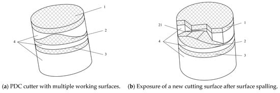
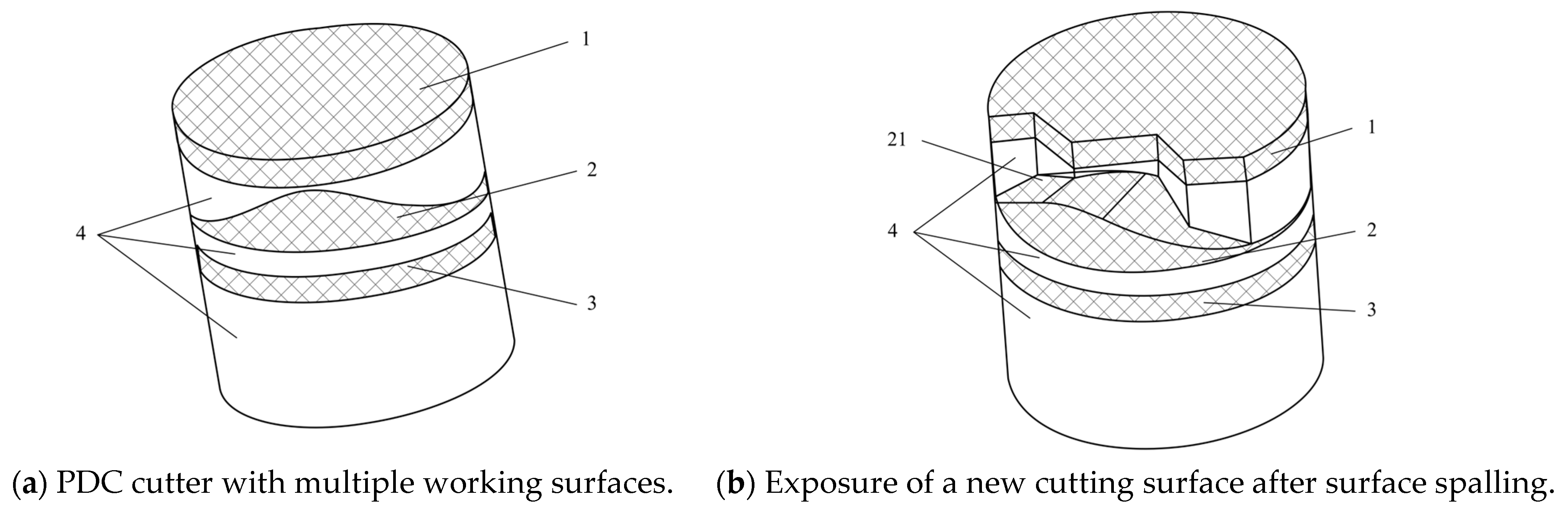
An assessment of bit wear and existing renewal technologies indicates that abrasive wear, fatigue fracture, and thermochemical processes progressively degrade cutter performance during rock breaking. Conventional replacement after wear can terminate the service life of an entire bit when only a local cutting unit fails. Renewal technologies actively adjust or replace worn cutting units to improve sustained operation and make fuller use of the remaining bit life. Existing approaches follow two principal routes: material-driven renewal and mechanical renewal. Material-driven renewal uses layered PDC cutters with multiple working surfaces. Wear progressively exposes a new working surface, providing passive renewal without external actuation. Figure 1 identifies a thin planar polycrystalline diamond layer (1), a curved polycrystalline diamond layer (2), a planar polycrystalline diamond layer (3), a cemented-carbide layer (4), and a second working surface (21). This structure has no moving components and offers high reliability. However, renewability depends on cutter wear, limiting active control over its timing and frequency. Fabrication complexity, cost, and consistency of interlayer properties also remain concerns. In complex heterogeneous formations, especially where drilling to total depth in a single bit run is required, material improvements alone offer limited active control over bit capability. Mechanically actuated, in situ downhole renewal of cutting structures is therefore needed.
Figure 1.
Schematic of material-driven renewal.
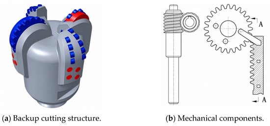
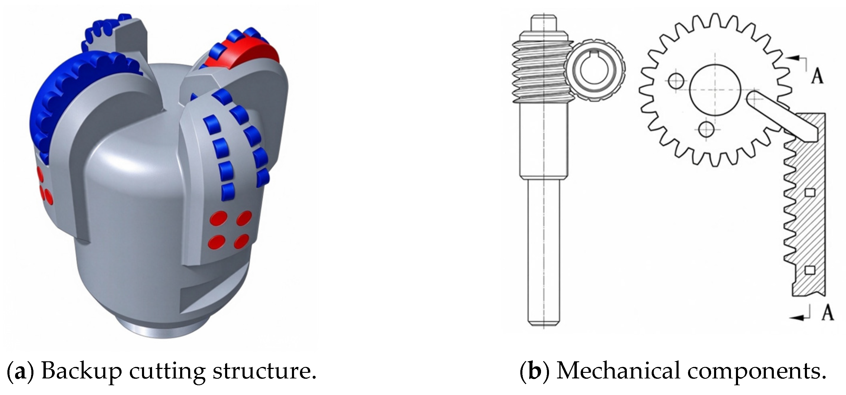
Mechanical renewal offers greater engineering applicability, as illustrated in Figure 2. The use of worm gear, rack-and-pinion, or screw mechanisms converts drilling-fluid pressure into controlled mechanical motion. Backup cutting structures rotate or translate along prescribed paths to achieve in situ downhole renewal. This approach provides an available power source, precise positioning, and adaptability to operating conditions. Mechanical self-locking can maintain a stable configuration after renewal. Mechanical actuation therefore offers a feasible route to repeated, reliable downhole renewal.
Figure 2.
Schematic of mechanical renewal.
The proposed renewal mechanism uses a worm gear transmission, as shown in the three-dimensional model in Figure 3. Smooth transmission, compact geometry, a high transmission ratio, and resistance to backdriving support precise indexing and stable positioning of the cutting structure. An 8-1/2-in., six-blade PDC bit was used as the reference design. Four modules were developed for pressure actuation, motion conversion and transmission, cutting-structure renewal, and position limiting. Theoretical analysis and numerical simulations assessed kinematic and force feasibility. A prototype was subsequently fabricated and tested on a full-scale rig to verify the renewal function, providing an engineering implementation of active downhole cutting-structure renewal.
Figure 3.
Three-dimensional model of the self-renewing bit driven by a single worm.
3. Structural Design of the Self-Renewing PDC Bit
3.1. Overall Structure and Operating Principle
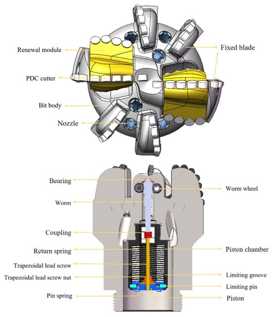
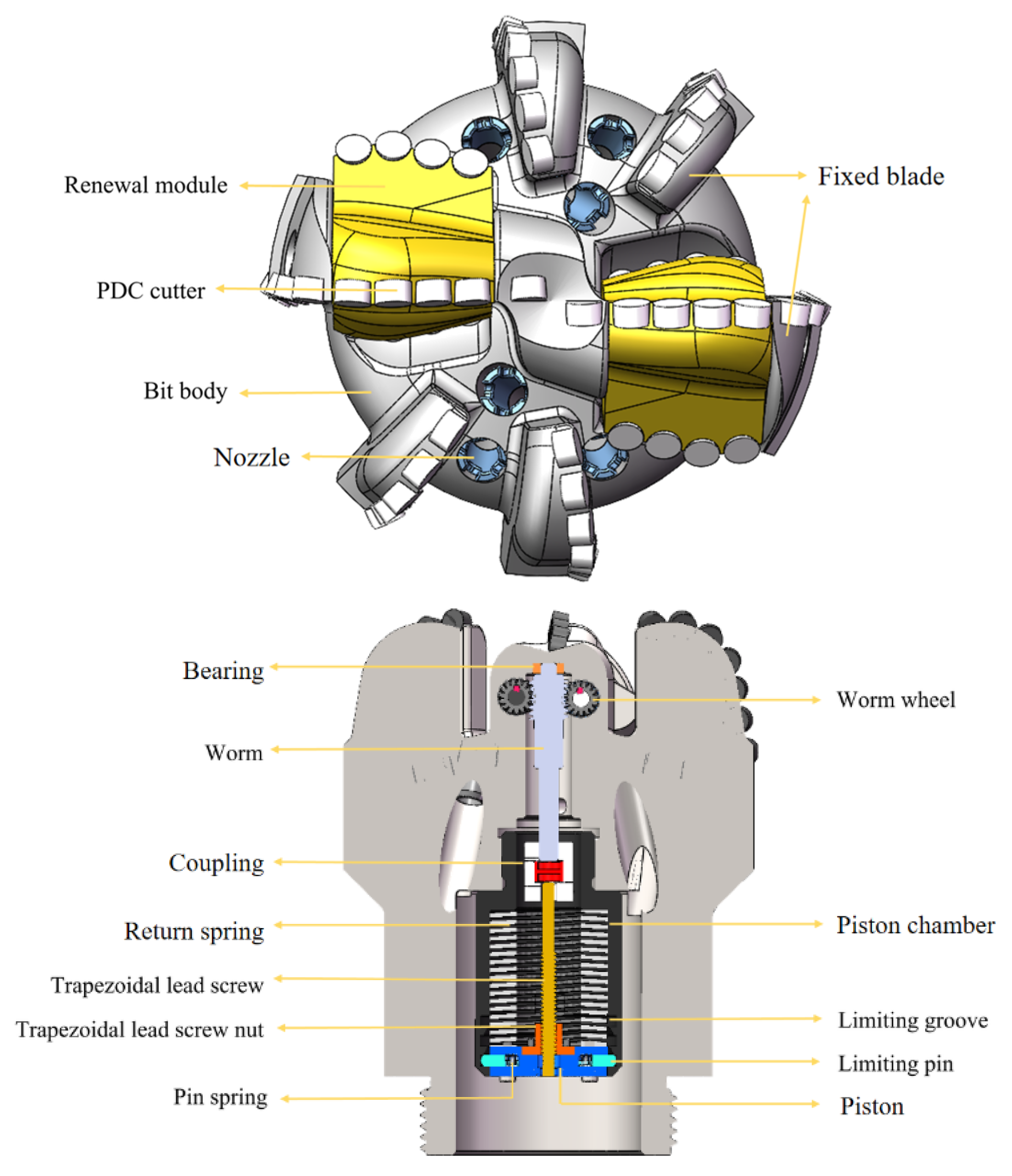
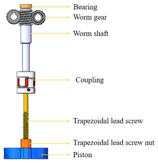
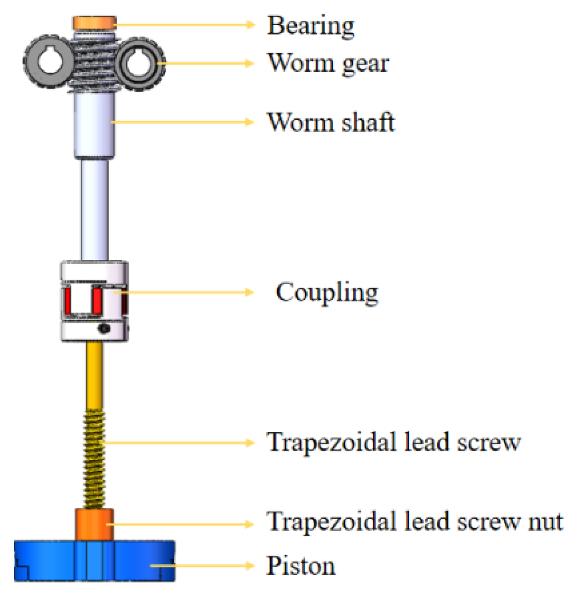
Figure 4 shows the structure of the self-renewing PDC bit. The central transmission uses one worm to drive a pair of worm wheels. The worm is positioned centrally, with its axis coincident with the bit axis. A bearing supports its upper end, while a coupling connects its lower end to a trapezoidal lead screw. The screw nut is rigidly connected to the piston. Position-limiting mechanisms are provided at the piston-chamber interface and the screw linkage. The renewal modules are oriented perpendicular to the radial direction of the bit. They are keyed to the transmission shaft, which is supported on both sides by the bit body.
Figure 4.
Schematic of the self-renewing PDC bit.
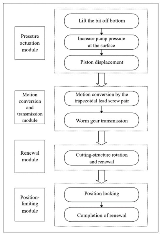
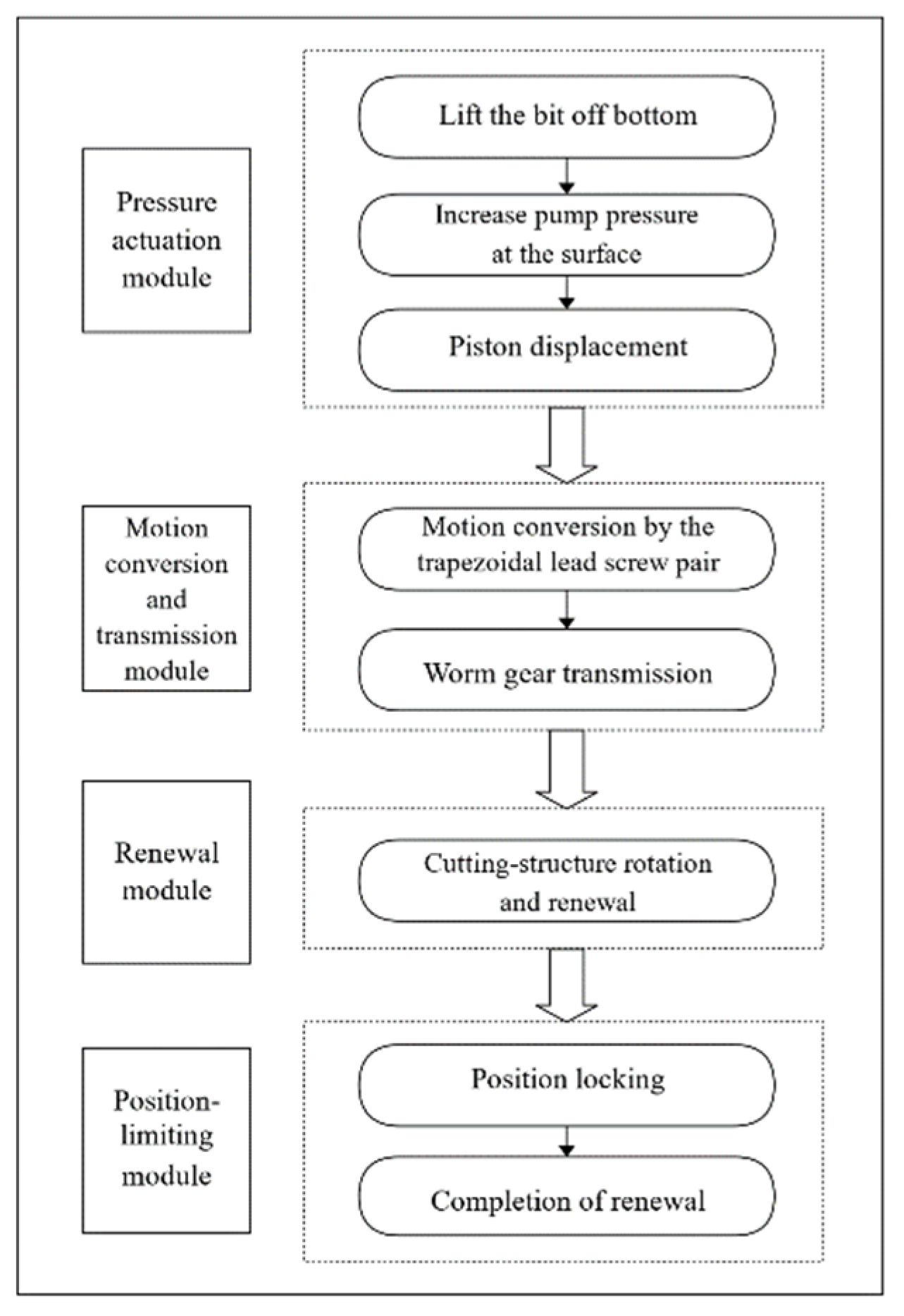
As shown in Figure 5, cutting-structure renewal is achieved through coordinated operation of the four modules. During normal drilling, the cutters on the renewal modules engage the rock as fixed cutters, while the worm gear transmission maintains stability through self-locking. When renewal is required, the drilling-fluid pressure is increased from the surface. This moves the piston and its rigidly connected screw nut. The screw pair converts axial nut motion into screw rotation, which drives the worm gear transmission through the coupling. The cutter wheels then rotate to replace worn cutters with backup cutters. At the prescribed piston position, the limiting pins engage the limiting grooves and prevent further travel, completing the renewal sequence.
Figure 5.
Operating principle of the self-renewing PDC bit.
3.2. Design of the Pressure Actuation Module
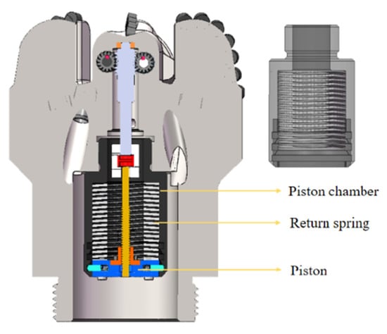
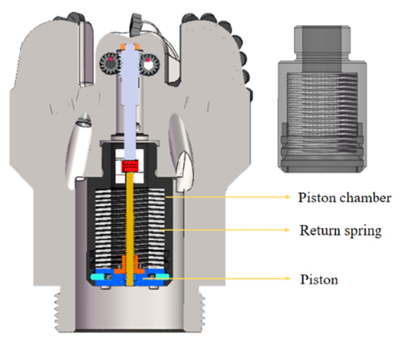
The bit uses a sliding-piston actuation mechanism comprising a piston, piston chamber, and return spring (Figure 6). Both sides of the piston are subjected to downhole hydrostatic pressure, and actuation depends on the effective pressure difference between them. In this design, the chamber below the piston is sealed and does not communicate directly with the annulus. The hydrostatic pressure contributions on the two sides are therefore considered to cancel out. During normal drilling, drilling-fluid pressure balances the spring preload, holding the piston stationary. Increasing the circulation pressure raises the pressure difference across the piston. Once the resulting force overcomes the spring preload and transmission resistance, the piston moves and drives cutting-structure renewal. The mechanism uses drilling-fluid pressure for actuation without additional downhole hydraulic components.
Figure 6.
Schematic of the sliding-piston actuation module.
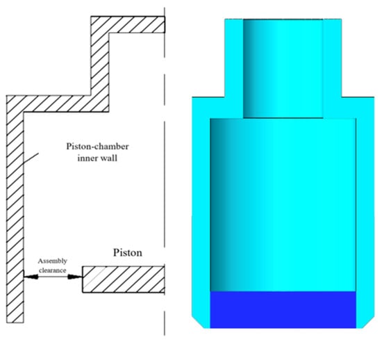
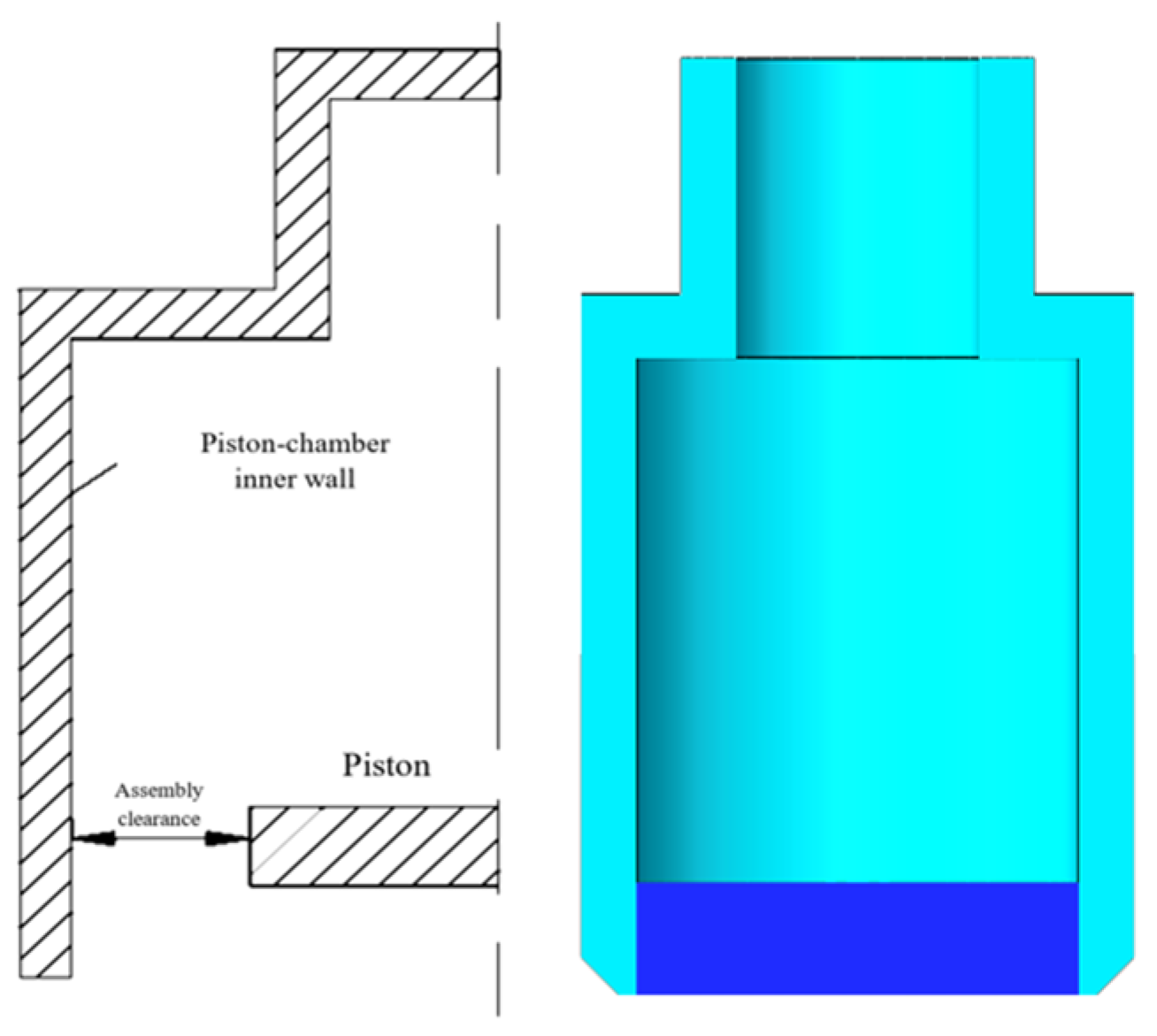
The clearance between the piston and its chamber directly affects pressure transmission. A larger clearance increases fluid leakage and reduces the pressure difference across the piston and the available driving force. Numerical analyses were therefore conducted to identify a suitable clearance range. Steady-state CFD simulations [25] used a bit model with a piston diameter of 60 mm. Four clearances were examined at 0.05, 0.10, 0.15, and 0.20 mm, as illustrated in Figure 7. An unstructured tetrahedral mesh was used. The inlet velocity was 3.82 m/s, corresponding to a flow rate of 30 L/s, and the outlet gauge pressure was 0 MPa. The working fluid was water at 25 °C. Gravity was included with g = 9.8 m/s2, and turbulence was modeled using the k-epsilon model.
Figure 7.
Planar and three-dimensional views of the assembly clearance.
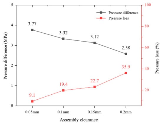
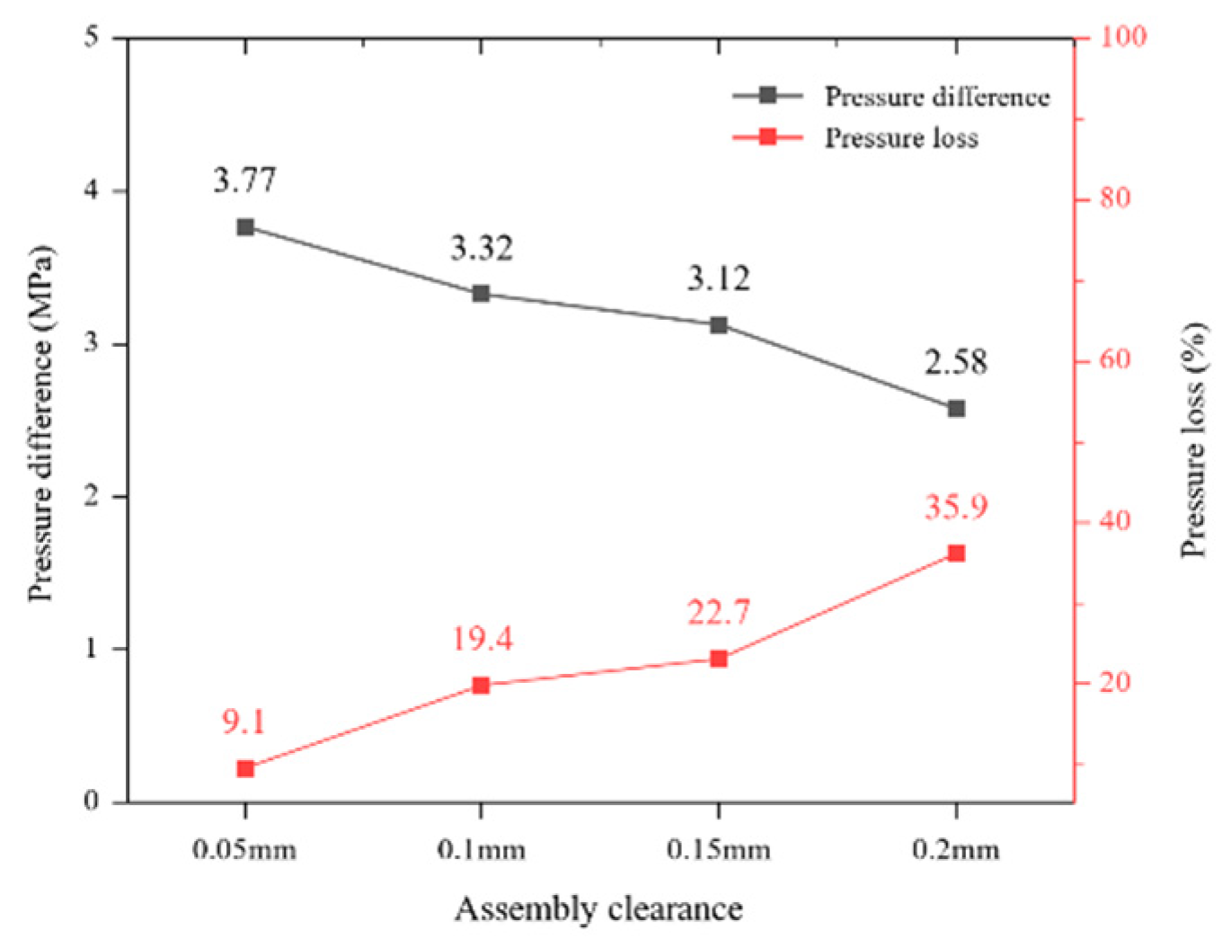
As shown in Figure 8, increasing the clearance from 0.05 to 0.20 mm reduced the pressure difference across the piston from 3.77 to 2.58 MPa. The pressure-loss percentage increased from 9.1% to 35.9%, indicating that leakage through a larger clearance reduced pressure transmission efficiency. At 0.10 mm, the pressure difference was approximately 12% lower than at 0.05 mm, with a pressure-loss percentage of 19.4%. The corresponding percentages at 0.15 and 0.20 mm were 22.7% and 35.9%, respectively. Balancing pressure transmission against manufacturing and assembly requirements, the clearance should be maintained at or below 0.15 mm. The actual activation pressure must also account for return-spring preload and transmission resistance.
Figure 8.
Effect of assembly clearance on the pressure difference across the piston.
3.3. Design of the Motion Conversion and Transmission Module
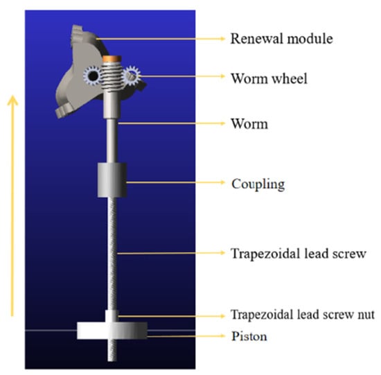
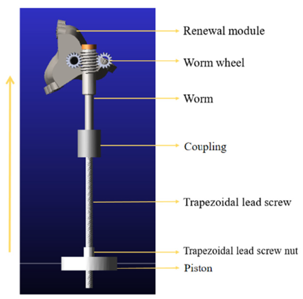
The motion conversion and transmission module comprises a trapezoidal screw pair and a worm gear pair (Figure 9). The screw pair converts axial nut motion into screw rotation. Its lead angle must prevent self-locking during backdriving. Conversely, the small lead angle of the single-start worm provides resistance to backdriving by the worm wheel, stabilizing the renewed cutting structure. During operation, drilling-fluid pressure moves the piston and its rigidly connected nut, causing the trapezoidal screw to rotate. The coupling transmits this rotation to the worm, and the worm wheels drive the renewal modules.
Figure 9.
Motion conversion and transmission module.
3.4. Design of the Renewal Module
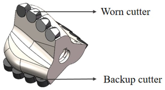
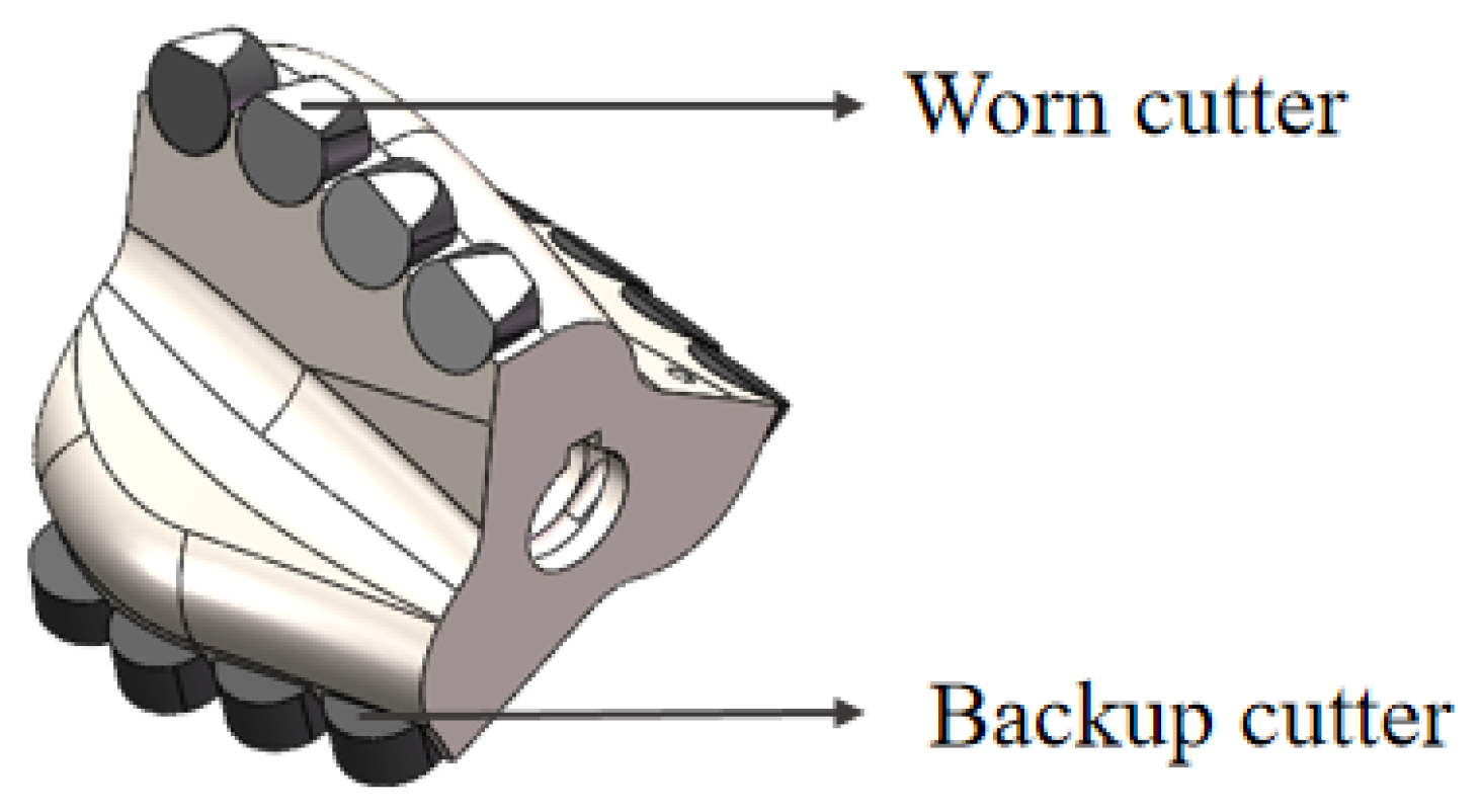
The renewal module contains one initial cutting structure and two backup cutting structures (Figure 10). After the initial structure becomes worn or damaged, rotation about the module axis brings a backup structure into the working position. The renewal module matches the cutting structure on the fixed blades to maintain the overall cutting performance of the bit.
Figure 10.
Renewal module.
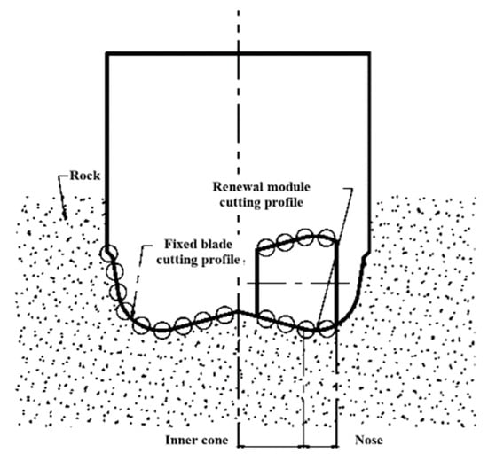
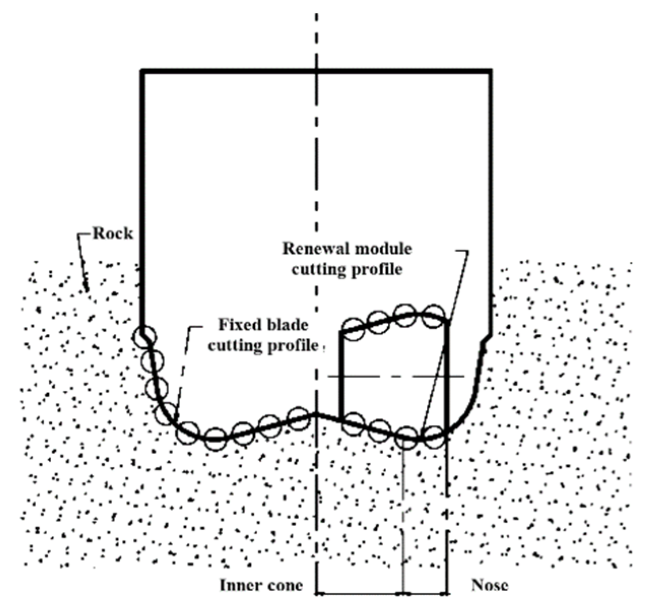
Figure 11 shows the cutting profile of the self-renewing PDC bit. The renewal modules cover approximately two-thirds of the inner cone and the nose, which are major wear regions during drilling. Renewing the cutting structures in these regions can extend bit service life. The renewal modules and fixed blades share a consistent cutting profile, forming a continuous, smooth cutting surface to maintain borehole quality.
Figure 11.
Cutting profile of the self-renewing PDC bit.
3.5. Design of the Position-Limiting Module
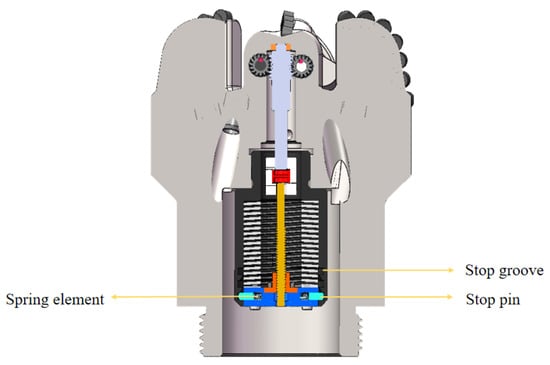
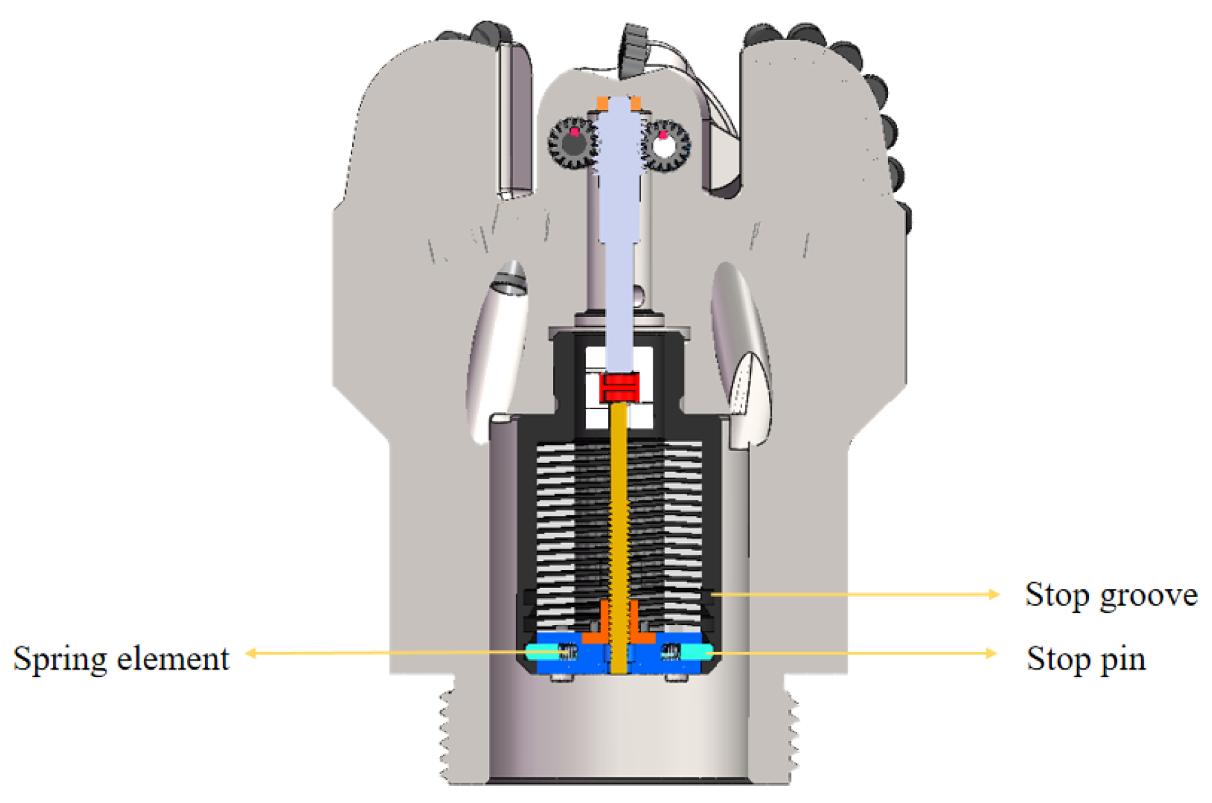
The position-limiting module combines return springs with a multistage mechanical limiting mechanism (Figure 12). It consists primarily of limiting pins and a piston chamber with multiple limiting grooves. Three locking positions are provided along the chamber wall. Spring-loaded limiting pins are arranged symmetrically on either side of the piston. Initially, the pins engage the first-stage grooves and lock the piston in its initial position. During the first renewal, hydraulic pressure moves the piston to the second-stage grooves, where the pins engage automatically. During the second renewal, hydraulic force overcomes the spring force and retracts the pins. The piston then travels to the third-stage grooves and locks again, completing the second renewal.
Figure 12.
Schematic of the position-limiting module.
4. Feasibility Analysis and Verification of the Renewal Function
4.1. Kinematic Feasibility of Renewal
A kinematic model was established using the motion transmission path in Figure 11. The model quantifies the input–output relationship of the internal transmission, relating piston translation to renewal-module rotation. Calculations were performed to assess whether the prescribed cutting-structure replacement could be achieved.
4.1.1. Piston-to-Screw Motion Conversion
The piston is rigidly connected to the trapezoidal screw nut. When drilling-fluid pressure produces axial piston displacement, the nut moves with the piston and drives screw rotation. The relationship between piston displacement and the number of screw revolutions is
where Nscrew is the number of screw revolutions (rev);
Spiston is the piston displacement (mm);
Ph is the trapezoidal screw lead (mm/rev).
Table 1 lists the parameters of the trapezoidal screw pair. Unlike conventional operation, nut translation drives screw rotation, so the screw pair must permit backdriving.
Table 1.
Parameters of the trapezoidal screw.
Self-locking was evaluated using Equations (2) and (3). The screw pair is not self-locking when λ > ρv:
where λ is the thread lead angle;
μ is the friction coefficient, taken as 0.15 for the stainless-steel screw pair under unlubricated conditions;
β is the thread flank angle, equal to 15°.
The calculated lead angle λ was 32.47°, exceeding the equivalent friction angle ρv of 8.83°. The screw pair therefore satisfies the conditions for backdriving.
4.1.2. Worm Gear Transmission
The trapezoidal screw is connected directly to the worm through a coupling, so both rotate synchronously [26,27]. Their rotational relationship is
The worm drives the worm wheel, whose number of revolutions is
where Nwormgear is the number of worm revolutions (rev);
Nworm is the number of worm-wheel revolutions (rev);
i is the transmission ratio of the worm gear pair.
Table 2 lists the dimensions of the worm gear pair. The theoretical transmission ratio is 15:1, converting five screw revolutions into 120° of worm-wheel rotation. This meets the requirement for one renewal operation.
Table 2.
Parameters of the worm gear pair.
Self-locking of the worm gear pair was evaluated using Equations (6) and (7). The self-locking condition is ≤ ρv:
where ρv is the equivalent friction angle;
γ is the worm lead angle;
μ is the friction coefficient, taken as 0.15 for the grade 45 steel worm gear pair under unlubricated conditions;
αn is the normal pressure angle, equal to 20°.
The calculated worm lead angle γ was 3.18°, which is below the equivalent friction angle ρv of 9.07°, satisfying the self-locking condition.
4.1.3. Overall Kinematic Relationship
Combining the two transmission stages gives the relationship between piston displacement and worm-wheel rotation. The total worm-wheel rotation angle θ is
4.1.4. Calculation-Based Verification
The design parameters in Table 3 were substituted into the kinematic relationship to verify the prescribed motion.
Table 3.
Design Parameters of the Renewal System.
Substitution into Equation (8) gives a worm-wheel rotation of 120°, which is equal to the rotation of the renewal module. This satisfies the requirement of indexing by one working position. The design is therefore kinematically feasible and provides the prescribed conversion from piston translation to renewal-module rotation.
4.2. Force Feasibility of Renewal
A load model was established to assess the force required for drilling-fluid pressure to drive the renewal modules. The model includes friction between the transmission shaft and bit body, additional fluid resistance, and resistance associated with debris entering the clearance. The required piston force was calculated by tracing these loads backward through the transmission chain.
4.2.1. Resisting Torque
The renewal modules are keyed to the two sides of the transmission shaft. Each is subjected to sliding friction at the shaft–bore interface, additional fluid resistance, and resistance caused by debris intrusion. With one renewal module on either side of the bit, the total resisting torque is
where T is the total resisting torque (N·m);
Tfluid is the resisting torque produced by drilling-fluid impingement on the cutting structure. It was calculated from the surface area of the renewal module and fluid velocity and taken as 1.1 N·m. The prototype experiment described below used water, whereas this load estimate represents drilling-fluid conditions. Differences in density and viscosity produce differences in fluid resistance. The water-based experiment therefore primarily examines actuation and renewal motion, while Tfluid represents the fluid resistance under drilling-fluid conditions.
Tdebris is the additional resisting torque associated with debris intrusion into the clearance, taken as 0.8 N·m.
Here, Fr is the radial force exerted on the shaft by one renewal module (N);
m is the mass of one renewal module (kg);
g is the gravitational acceleration, taken as 9.8 m/s2;
μ is the sliding friction coefficient at the shaft–bore interface, taken as 0.2 for unlubricated steel-on-steel contact;
r is the shaft-journal radius (mm).
Each renewal module has a mass of 1.17 kg, and the shaft radius is 8 mm. Equations (9) to (11) give a total resisting torque of 3.84 N·m for rotation of both modules.
4.2.2. Required Driving Force
The total worm-wheel load was referred back through the transmission chain to determine the required axial piston force. The calculation follows power balance and accounts for torque amplification and transmission losses. Applying the total resisting torque to the worm input requires the transmission ratio and efficiency:
where Tworm is the worm input torque (N·m);
i is the worm gear transmission ratio;
ηworm is the worm gear transmission efficiency, taken as 0.5.
The worm and screw are directly connected. The required screw torque is related to the axial nut force through the mechanics of the trapezoidal screw pair, including the return-spring preload:
where Tscrew is the required screw torque (N·m);
ηscrew is the transmission efficiency of the trapezoidal screw pair, taken as 0.4;
Fscrew is the required axial nut force (N);
Fspring is the spring preload. A rectangular-wire spring with a stiffness of 280.7 N/mm was selected.
Referring the loads through the transmission chain and including spring preload gives a required piston force of approximately 1818.5 N that drives both renewal modules.
4.2.3. Required Drilling-Fluid Pressure
The screw nut is rigidly connected to the piston, so drilling-fluid pressure supplies the required axial nut force. The minimum pressure required at the piston is
where Pmin is the minimum drilling-fluid pressure required to drive the piston (MPa);
S is the piston surface area (mm2).
The theoretical calculation gives a drilling-fluid pressure of approximately 1 MPa to actuate the mechanism and complete one cutting-structure renewal. This pressure is readily available during drilling. In practice, spring preload can increase the activation threshold to suit different pump-pressure conditions.
4.3. Dynamic Verification Using Adams
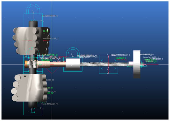
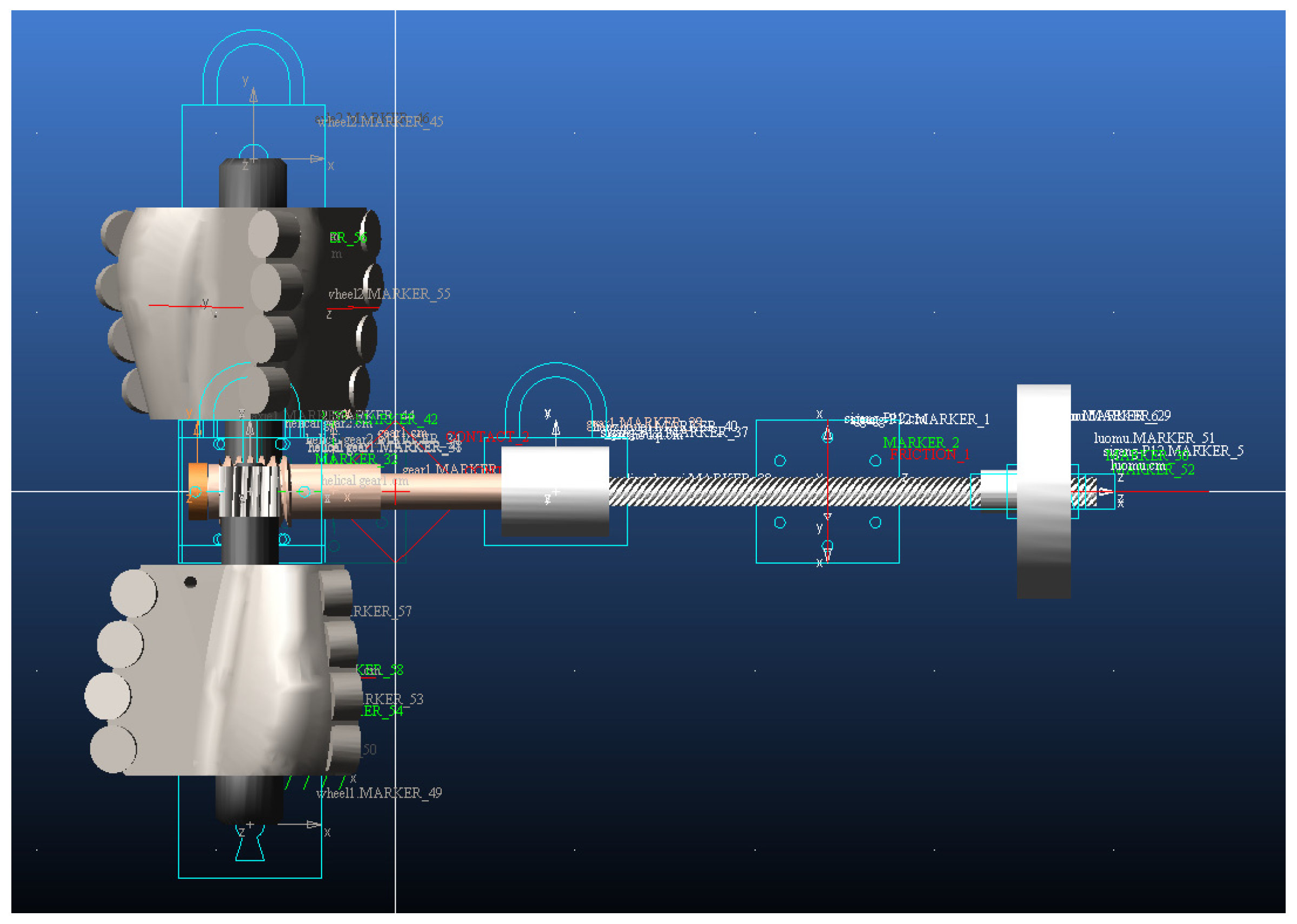
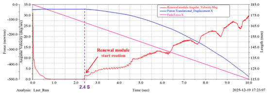
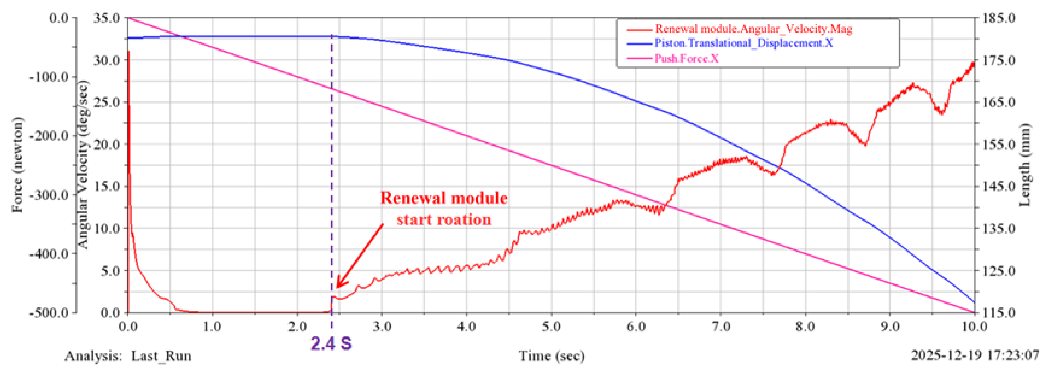
The Adams simulations excluded return-spring preload and primarily examined the basic dynamic response of the transmission system. Motion constraints and contact relationships were established for the screw and worm gear pairs according to the actual transmission configuration (Figure 13 and Figure 14). A prescribed translational drive of “14 × time” was applied to the screw nut, producing 70 mm of piston travel over 5 s. A characteristic point on the renewal module followed a 120° circular arc, consistent with the kinematic calculation. In a further simulation, each module was subjected to a resisting torque of 1.92 N·m, and the driving force increased at 50 N/s. As shown in Figure 15, the modules began rotating at 120 N. This differed by 4.3% from the theoretical value of 115 N, indicating agreement between the simulated and calculated transmission response.
Figure 13.
Motion constraints and contact relationships.
Figure 14.
Dynamic simulation results.
Figure 15.
Motion transmission path.
5. Experimental Verification of the Self-Renewing PDC Bit
5.1. Prototype Fabrication
A prototype was fabricated and assembled from the three-dimensional design to assess structural feasibility. Machining of the bit body included the blades, flow channels, nozzle holes, cutter-wheel slots, bearing bores, and cutter pockets. The PDC cutters were brazed into position, and the connection was installed.
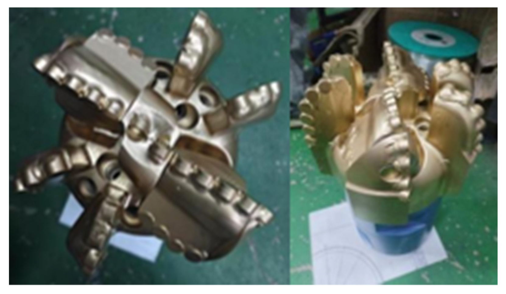
The renewal module comprises a cutter wheel and transmission shaft machined from SAE 4145H alloy steel. The shaft was quenched and tempered. The transmission module includes the worm gear mechanism and trapezoidal screw. The actuation module comprises the piston and piston housing, with the housing threaded into the bit body. After machining, the modules were assembled and their fits adjusted to produce the prototype shown in Figure 16.
Figure 16.
Prototype of the self-renewing PDC bit.
5.2. Renewal Performance Testing
5.2.1. Experimental Principle and Procedure
A laboratory test using hydraulic actuation was conducted to assess the feasibility and operational reliability of the downhole renewal function.
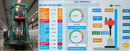
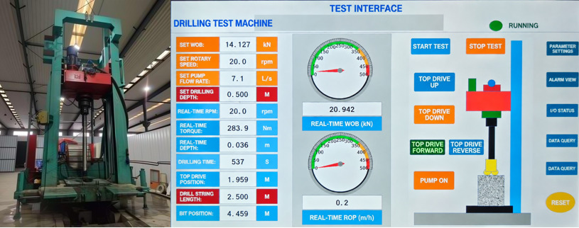
Testing was conducted at the Drill Bit Research Institute of Southwest Petroleum University using a YD100 bit test rig. Its dedicated pump provides continuously adjustable flow rates from 0 to 20 L/s. Weight on bit, torque, and rotational speed can also be controlled. The rig provides a maximum weight on bit of 300 kN, a maximum torque of 30,000 N·m, and a maximum speed of approximately 100 rev/min. Figure 17 shows the test rig and controls.
Figure 17.
YD100 bit test rig and controls.
Sensors were installed at the drill-string end to reduce disturbance from fluid jets. Load and displacement sensors measured weight on bit, torque, and displacement. The data acquisition system transferred the measurements synchronously to a computer for storage. The displacement sensor had a range of 0–16 m and a measurement error of ±0.5 mm. The weight-on-bit and torque channels had ranges of 0–300 kN and 0–20,000 N·m, respectively, with measurement errors of ±1%.
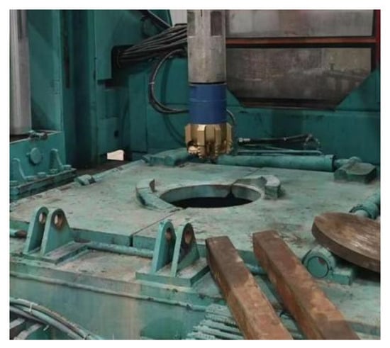
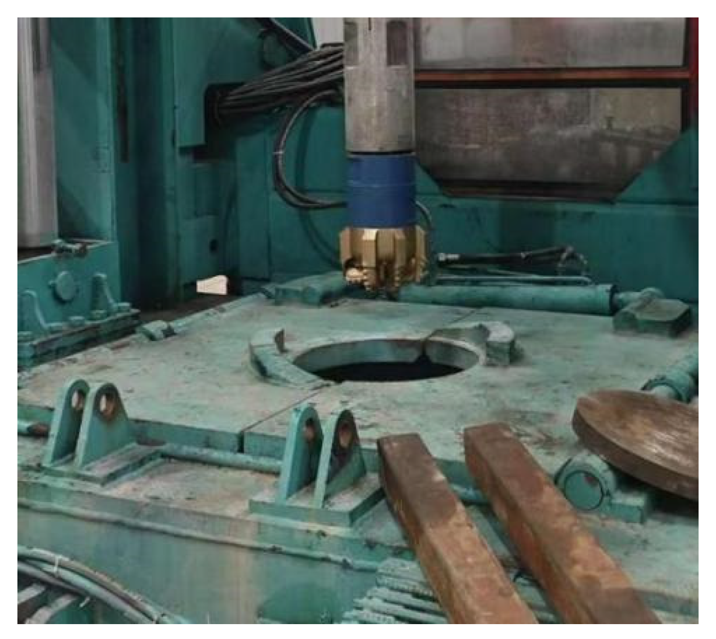
The experiment assessed the ability of the renewal modules to complete one renewal operation. The return spring and position-limiting module were removed to exclude their influence on the single-renewal sequence. The assembled prototype was connected to the YD100 rig with the transmission in its initial working position. Water was used as the driving medium. The rig included a dedicated pump with an adjustable flow rate of 0–20 L/s and a pressure sensor with a range of 0–20 MPa and an accuracy of ±0.5%. The experimental setup is shown in Figure 18.
Figure 18.
Prototype and mounting arrangement of the self-renewing PDC bit.
Pump pressure was increased from 0 MPa in increments of 0.2 MPa, each maintained for 5 s. Pressure and module motion were observed throughout the test. Once stable rotation was observed, pressure was held for another 5 s to confirm completion of the renewal, and then gradually reduced to atmospheric pressure. Piston displacement and module rotation were measured after testing and compared with the theoretical values. Testing was terminated if pressure continued increasing without module motion, abnormal noise occurred, or pressure fluctuated sharply.
5.2.2. Experimental Results
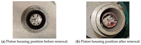
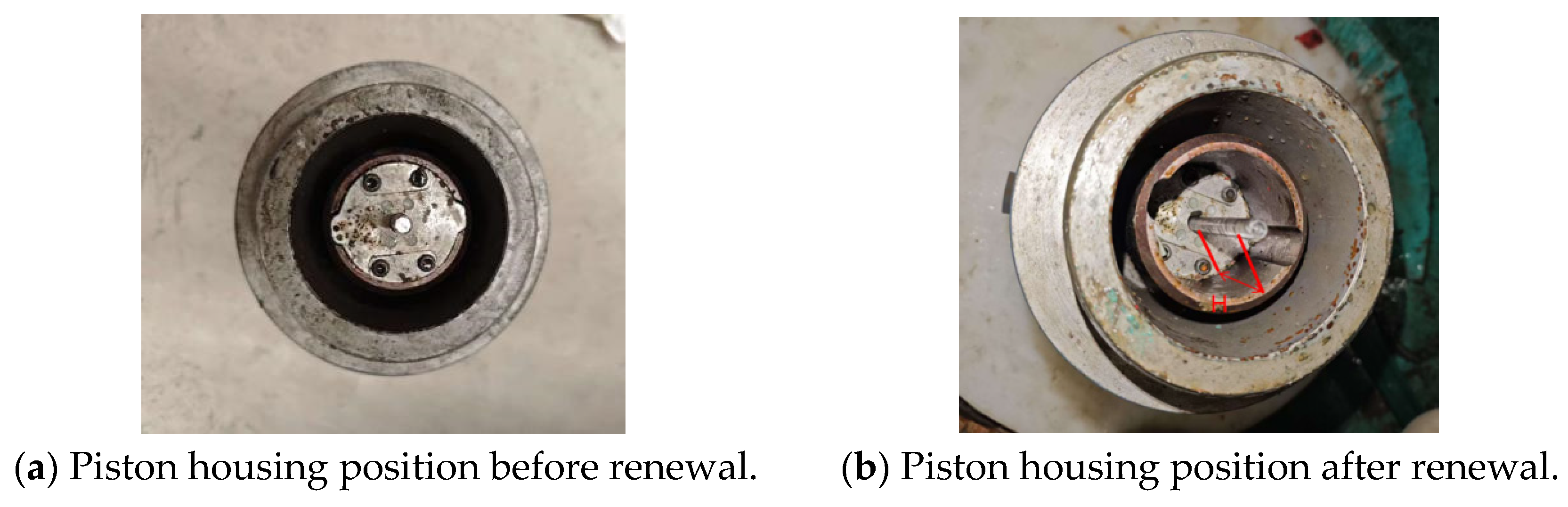
To illustrate the piston position changes before and after actuation of the renewal mechanism, a comparison of the initial and final piston positions is presented in Figure 19. The renewal modules began moving at a water pressure of 0.8 MPa and completed the renewal after a 5-s hold. The piston traveled 67 mm, and the cutter wheels rotated approximately 114°, achieving one cutting-structure renewal.
Figure 19.
Piston positions before and after renewal.
The theoretical activation pressure of 1 MPa includes the spring preload and therefore represents the combined effect of basic system resistance and spring loading. The return spring was removed during testing, so the measured pump pressure of 0.8 MPa corresponds to overcoming basic system resistance alone. Applying the 19.4% pressure loss associated with a 0.10-mm clearance in Section 3.2 gives an effective piston pressure of approximately 0.645 MPa. The corresponding thrust is approximately 1858 N, exceeding the theoretical estimate of the basic resistance without the spring. This difference is attributed primarily to interference fits, coaxiality deviations, actual static friction, and reduced efficiency across the transmission stages.
The design and measured parameters are compared in Table 4. The target piston displacement was 70 mm, and the target cutter-wheel rotation was 120°. The measured displacement H and rotation were 67 mm and 114°, respectively. The overall deviation was 5%, within the prescribed acceptable range, supporting the motion feasibility of the transmission system.
Table 4.
Comparison of theoretical and measured renewal parameters.
6. Conclusions
(1) A rotary self-renewing PDC bit actuated by drilling-fluid pressure was proposed to address the limited capability of conventional bits for active downhole restoration after cutter wear. A piston, trapezoidal screw, and worm gear transmission adjust the cutting-structure orientation. The design provides an approach to active renewal without requiring retrieval of the bit solely for cutting-structure replacement.
(2) CFD simulations assessed the effect of piston-chamber clearance on pressure transmission. Increasing the clearance from 0.05 to 0.20 mm reduced the pressure difference across the piston from 3.77 to 2.58 MPa. The pressure-loss percentage increased from 9.1% to 35.9%. Considering both pressure transmission and manufacturing requirements, the clearance should be maintained at or below 0.15 mm to support effective transmission of the driving force.
(3) A dynamic model was established to assess the resisting torque and driving-force requirement during renewal. Including shaft friction, additional drilling-fluid resistance, and debris-intrusion resistance gave a total resisting torque of 3.84 N·m and a theoretical piston force of approximately 115 N. In the Adams simulation, the renewal modules began moving at 120 N, a deviation of 4.3% from the theoretical value. This comparison supports the dynamic model of the transmission system.
(4) Laboratory prototype testing assessed the operating capability of the renewal mechanism. At a water pressure of 0.8 MPa, the piston traveled 67 mm and rotated the renewal modules by approximately 114°, achieving one cutting-structure renewal. The results indicate that drilling-fluid pressure actuation combined with worm gear transmission can provide stable cutting-structure renewal. Seal reliability during long-term downhole operation, compatibility with drilling fluids, and drilling performance after renewal require further investigation.
Author Contributions
Conceptualization, X.L.; Methodology, X.L.; Software, Q.W.; Validation, Q.W.; Formal analysis, K.H.; Investigation, K.H.; Resources, X.W.; Data curation, X.W.; Writing—original draft, J.Y.; Writing—review and editing, H.R.; Visualization, G.J.; Supervision, G.J.; Project administration, H.R.; Funding acquisition, J.Y. All authors have read and agreed to the published version of the manuscript.
Funding
This research was funded by the Complex deep underground safe and efficient drilling and completion technology and equipment grant number [2025ZD1401902], the Synthesis of composite sheets of ultra-high pressure and superhard materials, upgrading of drill bit technology, and on-site testing grant number [2026ZS003], Nanchong City–Southwest Petroleum University City-School Science and Technology Strategic Cooperation Project grant number [23XNSYX0018], the Deep Earth Probe and Mineral Resources Exploration–National Science and Technology Major Project grant number [2025ZD1008300].
Data Availability Statement
The original contributions presented in this study are included in the article. Further inquiries can be directed to the corresponding author(s).
Conflicts of Interest
Authors Xiaoao Liu, Qiang Wu, Xinyue Wu, Jinping Yu and Guodong Ji were employed by the CNPC Engineering Technology R&D Company Limited. The remaining authors declare that the research was conducted in the absence of any commercial or financial relationships that could be construed as a potential conflict of interest.
References
- Wang, H.G.; Huang, H.C.; Bi, W.X.; Ji, G.D.; Zhou, B.; Zhuo, L.B. Advances and prospects in oil and gas drilling technologies for deep and ultradeep wells. Nat. Gas Ind. 2021, 41, 163–177. (In Chinese) [Google Scholar]
- Li, H.Y. Exploring the Frontiers of Deep Exploration Through Collaboration: The Third Forum on Deep and Ultradeep Well Oil and Gas Development Concludes. China Daily, 21 July 2025. (In Chinese)
- Wang, X.C. Deep and Ultradeep Well Drilling Technologies: Technical Progress and Future Trends. Institute of Geology and Geophysics and Institute of Earth Sciences, Chinese Academy of Sciences, 3 January 2023. (In Chinese)
- Gao, L.D.; Huang, W.J. Advances and recommendations in ultradeep well engineering theory and technology. Pet. Drill. Technol. 2024, 52, 1–11. (In Chinese) [Google Scholar]
- Deng, H.; Jia, L.C. Advances and prospects in key technologies for deep and ultradeep oil and gas drilling in the Sichuan Basin. Nat. Gas Ind. 2022, 42, 82–94. (In Chinese) [Google Scholar]
- Wang, Z.G.; Wang, W.S.; Zhang, L.Y.; Xi, Z.; An, D.; Yin, H.; Wang, W.; Yan, J. Current status and prospects of drilling and completion technologies for 10,000-m scientific ultradeep wells. Sci. Technol. Rev. 2022, 40, 27–35. (In Chinese) [Google Scholar]
- Yin, H.; Zhao, X.W.; Li, Q. Selection of drill bits for deep and ultradeep wells using entropy-weighted Vague sets. In Proceedings of the 2022 China Intelligent Oil and Gas Technology Conference, the Fifth Forum on Artificial Intelligence in the Petroleum and Petrochemical Industry, and the Eighth Intelligent Digital Oilfield Forum; Beijing Energy Association: Beijing, China; China University of Petroleum: Beijing, China; State Key Laboratory of Petroleum Resources and Prospecting: Beijing, China; State Key Laboratory of Heavy Oil Processing: Beijing, China; Baidu Intelligent Cloud: Beijing, China, 2022; pp. 178–185. (In Chinese) [Google Scholar]
- Zuo, H.G.; He, F.Y.; Yan, W.F.; He, P.F.; Li, X.D. Customized PDC bit design and its application in ultradeep wells in the East China Sea. Technol. Superv. Pet. Ind. 2020, 36, 17–22. (In Chinese) [Google Scholar]
- Rashidi, B.; Hareland, G.; Tahmeen, M.; Anisimov, M.; Abdorazakov, S. Real-Time Bit Wear Optimization Using the Intelligent Drilling Advisory System. In Proceedings of the 2010 SPE Russian Oil & Gas Technical Conference and Exhibition, Moscow, Russia, 26–28 October 2010; OnePetro: Richardson, TX, USA, 2010. [Google Scholar]
- Yang, H.; Wang, C.S.; Yang, X.Z.; Zhang, Z.; Guo, X.G.; Sun, C.H.; Lu, X.G.; Liu, J.L. Advances in key drilling technologies and scientific significance of the 10,000-m-class ultradeep Shendi Take 1 well. Pet. Explor. Dev. 2025, 52, 1180–1188. (In Chinese) [Google Scholar]
- Southwest Petroleum University. Cutting Structure and PDC Bit for Highly Abrasive Formations. 202311756192.4, 23 July 2024. (In Chinese) [Google Scholar]
- Zhang, C.; Sun, J.S.; Huang, X.B.; Lu, K.H.; Wang, J.T.; Li, J.; Geng, Y.; He, J.; Dai, J.J. Advances and prospects in cooling technologies for drilling fluids in deep and ultradeep wells. Chin. J. Eng. 2025, 47, 1161–1174. (In Chinese) [Google Scholar]
- Baker Hughes Incorporated. Adaptive Control Scheme for a PDC/Roller-Cone Hybrid Bit. US20100270085A1, 28 October 2010. [Google Scholar]
- Cui, G.; Cao, P.; Zhang, Y. Design and rigid body dynamics analysis of a novel retractable drill bit used in casing-while-drilling. Proc. Inst. Mech. Eng. Part E J. Process Mech. Eng. 2026, 240, 281–291. [Google Scholar] [CrossRef] [Scilit]
- Zhang, C.; Wang, J.; Ke, X.; Yang, Y.; Ren, H.; Niu, S.; Cai, C. Rock-breaking performance analysis of worn polycrystalline diamond compact bit. Geoenergy Sci. Eng. 2023, 221, 211352. [Google Scholar] [CrossRef] [Scilit]
- Liu, X.; Ji, G.; Yang, L.; Ren, H.; Wu, Q.; Yu, J.; Huang, K. Polycrystalline Diamond Composite Bit Technology for Sustainable Work. Processes 2025, 13, 421. [Google Scholar] [CrossRef] [Scilit]
- Yang, Y.X.; Zeng, H.; Ma, J.; Zhang, L.; He, X.; Fan, X.L.; Lin, M. Embedded secondary-cutter technology for PDC bits. Acta Pet. Sin. 2008, 29, 612–614. (In Chinese) [Google Scholar]
- Southwest Petroleum University; Chengdu Weiyi Petroleum Technology Co., Ltd. Long-life PDC Bit with Translating Blades. 201810103381.4, 18 May 2018. (In Chinese) [Google Scholar]
- Southwest Petroleum University; Chengdu Weiyi Petroleum Technology Co., Ltd. PDC Bit with Partially Movable Blades. 202210075971.7, 18 February 2025. (In Chinese) [Google Scholar]
- Southwest Petroleum University; Chengdu Weiyi Petroleum Technology Co., Ltd. Long-Life PDC Bit with Indexable Blades. 201810103009.3, 13 October 2023. (In Chinese) [Google Scholar]
- Southwest Petroleum University; Chengdu Weiyi Petroleum Technology Co., Ltd. Long-Life Drill Bit with Self-Repair Capability. 201610281540.0, 15 March 2019. (In Chinese) [Google Scholar]
- Southwest Petroleum University. Long-Life Drill Bit with Downhole Self-Renewal Capability. 202410872472.X, 30 August 2024. (In Chinese) [Google Scholar]
- Sichuan Branch of Shanghai Datan Energy Technology Co., Ltd. PDC Bit with Automatic Downhole Cutter Replacement and Replacement Method. 202510748897.4, 8 August 2025. (In Chinese) [Google Scholar]
- Liao, G.R. A Bioinspired Adaptive PDC Bit with Self-Protection Capability. Master’s Thesis, Jilin University, Changchun, China, 2025. (In Chinese) [Google Scholar] [CrossRef]
- Sundaram, N.M.; Ezhilarasan, C.; Kumar, A.J.P.; Betala, R. Analysis of multipoint cutting tool temperature using FEM and CFD. Manuf. Rev. 2018, 5, 16. [Google Scholar] [CrossRef] [Scilit] [PubMed]
- Bloch, H.P.; Perez, R.X. Industrial Drive Couplings. In Process Machinery Handbook; Perez, R.X., Ed.; Wiley: Hoboken, NJ, USA, 2025. [Google Scholar] [CrossRef] [Scilit]
- Childs, P.R.N. Mechanical Design, 3rd ed.; Elsevier: Amsterdam, The Netherlands, 2021. [Google Scholar]

Disclaimer/Publisher’s Note: The statements, opinions and data contained in all publications are solely those of the individual author(s) and contributor(s) and not of MDPI and/or the editor(s). MDPI and/or the editor(s) disclaim responsibility for any injury to people or property resulting from any ideas, methods, instructions or products referred to in the content. |
© 2026 by the authors. Licensee MDPI, Basel, Switzerland. This article is an open access article distributed under the terms and conditions of the Creative Commons Attribution (CC BY) license.