


Abstract
Thermoelectric modules enable direct conversion between thermal and electrical energy and offer attractive opportunities for waste-heat recovery, solid-state refrigeration, electronics cooling, renewable energy harvesting, and thermal control. Although considerable progress has been achieved in enhancing the thermoelectric figure of merit of constituent materials, practical device performance is frequently constrained by heat transfer processes occurring within the thermoelectric legs, across material interfaces, and between the module and external heat sources and sinks. This review provides a comprehensive assessment of the heat transfer challenges governing thermoelectric modules and devices and critically evaluates thermal management strategies from the material to system scale. The fundamental coupling among thermoelectric effects, Fourier conduction, and Joule heating processes is first presented, followed by analysis of contradictory thermal requirements, phonon transport, temperature-dependent properties, thermal contact resistance, heat leakage, parasitic losses, temperature nonuniformity, and transient thermal loads. Particular attention is given to advanced heat rejection and heat supply technologies, including optimized finned heat sinks, microchannel heat sinks, jet impingement, heat pipes, vapor chambers, and phase change materials. Emerging approaches involving nanostructured thermal interfaces, additive manufacturing, machine-learning-assisted optimization, and hybrid cooling are critically assessed. The review identifies a transition from component-level thermal-resistance minimization toward integrated material–interface–device–heat-exchanger co-design. Major research needs include transient experimental datasets, physics-informed artificial intelligence, scalable manufacturing, and validation under realistic operating conditions. Future thermoelectric systems will require simultaneous optimization of heat transfer, electrical performance, auxiliary energy consumption, mechanical reliability, manufacturability, and lifecycle performance.
1. Introduction
The continuing growth in global energy consumption, coupled with the need to reduce greenhouse gas emissions and improve energy efficiency, has intensified interest in technologies capable of recovering otherwise wasted thermal energy. Among available waste-heat recovery technologies, thermoelectric (TE) conversion is particularly attractive because it enables direct conversion between thermal and electrical energy without mechanical components or circulating working fluids [1,2,3,4]. Their solid-state construction provides compactness, silent operation, modularity, scalability, high reliability, and low maintenance requirements [5,6]. These characteristics have enabled applications in industrial and automotive waste-heat recovery, spacecraft power systems, solar-energy conversion, electronics cooling, refrigeration, biomedical equipment, and autonomous sensors [6,7,8]. However, the intrinsic performance of a thermoelectric material is commonly characterized by the dimensionless figure of merit, , where S is the Seebeck coefficient, σ is the electrical conductivity, k is total thermal conductivity, and T is absolute temperature [3,4]. High thermoelectric performance therefore requires a large Seebeck coefficient and high electrical conductivity, together with low thermal conductivity. These requirements are intrinsically coupled, because increasing carrier concentration generally improves electrical conductivity but can increase electronic thermal conductivity. Consequently, high-performance thermoelectric materials require simultaneous control of electron and phonon transport [9,10,11].
Considerable progress has been achieved through low-dimensional structures, nanostructuring, electronic-band engineering, and hierarchical phonon scattering [12,13,14,15,16,17,18]. Nanostructured BiSbTe alloys have demonstrated that enhanced phonon scattering at grain boundaries and defects can suppress lattice thermal conductivity while preserving useful electrical transport [15]. Band-structure engineering provides a complementary approach by modifying electronic transport, while hierarchical architectures combine atomic-scale disorder, nanoscale precipitates, and mesoscale grain boundaries to scatter heat-carrying phonons over multiple length scales [16,17]. These developments have produced substantial improvements in material performance, establishing phonon and electron engineering as central strategies for thermoelectric-material optimization. However, improvements in material performance do not translate directly into equivalent improvements in practical device efficiency or power density. A thermoelectric module comprises active TE legs together with electrodes, diffusion barriers, bonding layers, ceramic substrates, thermal interface materials (TIMs), packaging, and external heat exchangers. The source-to-sink temperature difference is therefore distributed across a network of thermal resistances rather than being imposed entirely across the active thermoelectric material [7,19]. This distinction is fundamental because thermoelectric performance is determined by the actual thermal conditions experienced by the active elements rather than solely by their intrinsic material properties.
Heat transfer therefore provides the critical link between thermoelectric material performance and practical system performance. In thermoelectric generators (TEGs), efficient hot-side coupling is required to transfer thermal energy from the source, while low-resistance cold-side heat rejection is necessary to maintain a large temperature difference across the TE elements. Excessive thermal resistance on either side reduces the useful temperature gradient and electrical output. For thermoelectric coolers (TECs), hot-side thermal management is even more demanding because the heat exchanger must dissipate both the heat pumped from the cold side and the electrical energy supplied to the module. Inadequate heat rejection consequently raises the hot-side temperature and reduces cooling capacity and coefficient of performance (COP) [2,6]. Thermal contact resistance and parasitic heat leakage further constrain device performance. Surface roughness, microscopic voids, oxide layers, bonding materials, and imperfect contact introduce additional temperature drops at material interfaces. Meanwhile, electrodes, ceramic substrates, encapsulation, and structural components provide parasitic thermal pathways that bypass the active thermoelectric elements. As intrinsic material properties improve, these device-level losses can represent an increasingly significant fraction of the total thermal resistance and may limit the system-level benefits obtained from further increases in material performance [7,18,20]. Practical heat sources such as exhaust streams, industrial equipment, solar absorbers, and electronic components impose spatially and temporally nonuniform thermal loads. Individual TE couples may therefore operate at different temperature differences, producing nonuniform electrical output or cooling performance, and these limitations have stimulated the development of advanced thermal management technologies.
Although substantial reviews are available on thermoelectric materials, TEG/TEC technologies, and individual cooling approaches, the heat-transfer processes connecting these levels are often treated separately. Consequently, the pathway through which intrinsic material properties are translated into practical modules and system performance remains insufficiently synthesized. Improvements in ZT do not necessarily produce proportional improvements in device efficiency, while auxiliary fan or pump consumption can further reduce net system benefits. This review therefore adopts heat transfer as a unifying framework across the material–interface–module–device–system hierarchy. Particular emphasis is placed on the interactions among phonon transport, thermal contact resistance, parasitic heat leakage, temperature nonuniformity, transient loads, advanced heat exchangers, and phase-change thermal management and on how these interactions ultimately determine TEG net power and TEC system COP. Figure 1 provides the overall framework of this review, linking the principal heat-transfer challenges across characteristic length scales to their effects on TEG/TEC performance and the corresponding thermal-management strategies.
Figure 1.
Overall framework linking multiscale heat-transfer challenges, their effects on TEG/TEC performance, and corresponding thermal-management strategies.
A structured literature-search procedure was employed to identify studies addressing heat-transfer phenomena and thermal-management technologies in thermoelectric materials, modules, generators, and coolers. The primary literature search covered publications from 2006 to 2026, with particular emphasis on studies published during the most recent five years. Earlier seminal studies were additionally retained where they provided fundamental thermoelectric theory, established widely adopted thermal-management concepts, or reported benchmark experimental results. Search terms included combinations of “thermoelectric generator”, “thermoelectric cooler”, “thermoelectric module”, “heat transfer”, “thermal management”, “thermal contact resistance”, “thermal interface material”, “heat sink”, “microchannel”, “jet impingement”, “heat pipe”, “vapor chamber”, and “phase change material”. Studies were included when they provided quantitative or mechanistic information relevant to thermal transport or thermal management at the material, interface, module, device, or system scale.
2. Fundamentals of Thermoelectric Heat Transfer
2.1. Thermoelectric Effects
The operation of thermoelectric devices is governed primarily by three interconnected phenomena: the Seebeck, Peltier, and Thomson effects [1,3,4]. Figure 2 shows the schematic diagram of the three thermoelectric effects [21]. The Seebeck effect describes the generation of an electrical potential when a temperature difference exists across a thermoelectric material. Charge carriers at the high-temperature region possess greater thermal energy and diffuse toward the lower-temperature region, resulting in charge separation and the development of an electrical voltage. For a material over a sufficiently small temperature range, the generated voltage can be approximated by , where V is the thermoelectric voltage and is the temperature gradient. This phenomenon provides the physical basis for TEGs, in which p-type and n-type thermoelectric elements are electrically connected in series and thermally arranged in parallel to generate useful electrical power from an imposed temperature difference [1,6]. The magnitude of S depends strongly on material composition, charge-carrier concentration, electronic band structure, and temperature. Conventional metals generally exhibit relatively small Seebeck coefficients, typically around 1–10 μV/K, whereas doped semiconductors commonly exhibit substantially higher values of approximately 100–1000 μV/K.
Figure 2.
Schematic diagram of thermoelectric effects. (a) Seebeck effect, (b) Peltier effect, (c) Thomson effect. Reproduced from Zhang et al. [21], licensed under CC BY 4.0.
The Peltier effect represents the reciprocal thermoelectric phenomenon. When an electrical current passes through the junction between two dissimilar conductors or semiconductors, heat is either absorbed or released depending on the direction of current flow. The Peltier heat rate is given by , where is the Peltier coefficient and I is the electrical current. This mechanism forms the basis of thermoelectric refrigeration and temperature control [6]. The direction of heat pumping can be reversed simply by reversing the electrical current, allowing the same module to provide either cooling or heating. The heat transported by the Peltier effect is proportional to current, whereas resistive Joule heating increases approximately with the square of current. Consequently, increasing electrical current does not indefinitely increase useful cooling; an optimum current generally exists because Joule heating progressively offsets Peltier cooling.
The Thomson effect occurs when an electrical current flows through a homogeneous thermoelectric material subjected to a temperature gradient. The Thomson heat generation can be expressed as , where denotes the Thomson coefficient. Depending on the current direction and temperature dependence of the Seebeck coefficient, heat can be continuously absorbed or released within the material [3,22]. The Thomson contribution is often neglected in simplified thermoelectric models because it may be relatively small when the Seebeck coefficient varies weakly with temperature. However, this assumption can become inaccurate for large temperature differences or strongly temperature-dependent materials [22].
2.2. Heat Transfer Mechanisms
Heat transfer in a practical thermoelectric device involves conduction, convection, and radiation, together with thermoelectric heat transport and internally generated Joule heat. Conduction is the dominant mechanism within thermoelectric legs, metallic electrodes, ceramic substrates, solder layers, and TIMs. Fourier heat conduction can be expressed as . The total thermal conductivity of a thermoelectric material contains electronic and lattice contributions. Suppressing lattice thermal conductivity through phonon scattering while retaining efficient electrical carrier transport is therefore a central strategy in thermoelectric material engineering [3,4,19].
Figure 3 illustrates the thermal-resistance-chain framework governing heat transfer through TEG. The available source-to-sink temperature difference is progressively reduced by thermal resistances associated with the hot-side heat collector, interfaces and packaging, thermoelectric module, parasitic heat leakage, and cold-side heat sink [23]. Consequently, only a fraction of the external temperature difference is established directly across the thermoelectric legs. TEG performance therefore requires coordinated optimization of the complete thermal-resistance chain rather than isolated enhancement of individual components. Heat must first be efficiently transferred from an external source to the hot surface of a TEG and subsequently removed from its cold surface. Similarly, a TEC must absorb heat efficiently at its cold side while rejecting both the transported heat and electrical input energy at its hot side. External convective thermal resistances can therefore consume a substantial fraction of the source-to-sink temperature difference [2,6]. Heat exchanger design can therefore have a significant influence on practical thermoelectric performance comparable with that of the module itself [2,6]. Thermal radiation can become increasingly important at elevated temperatures. Radiation shielding, surface emissivity, and geometric configuration must therefore be considered when evaluating the complete thermal resistance network of high-temperature thermoelectric systems.
Figure 3.
Schematic of thermal-resistance-chain governing heat transfer through TEG.
3. Heat Transfer Challenges in Thermoelectric Materials
3.1. Contradictory Thermal Requirements
Efficient thermoelectric conversion requires maintaining a substantial temperature difference between the hot and cold sides of a device while simultaneously transporting electrical charge with minimal resistive losses. These requirements are difficult to achieve simultaneously because the transport coefficients are not independent. Furthermore, improving electrical conductivity generally increases the electronic contribution to thermal conductivity [3,9].
Several strategies have been developed to overcome this contradiction. Pei et al. [24] demonstrated band convergence in PbTe-based thermoelectric materials, whereby multiple valence bands with similar energies increase the effective carrier degeneracy and enhance the Seebeck coefficient without imposing a correspondingly severe reduction in electrical conductivity. This approach provides an effective route to increasing the thermoelectric power factor while retaining charge transport. Heremans et al. [16] demonstrated that Tl doping in PbTe introduces a resonant distortion in the electronic density of states near the Fermi level, substantially enhancing the Seebeck coefficient while preserving electrical conductivity. These results established resonant-level engineering as an important strategy for manipulating electronic transport beyond conventional carrier-concentration optimization. Zhao et al. [25] demonstrated exceptionally low lattice thermal conductivity in single-crystalline SnSe, attributed to its strong anharmonic bonding, anisotropic crystal structure, and associated suppression of phonon transport. The combination of intrinsically weak lattice thermal transport with favourable electronic properties resulted in a high thermoelectric figure of merit, illustrating the considerable potential of phonon-engineered or intrinsically low-thermal-conductivity materials. Nevertheless, the fundamental coupling among the Seebeck coefficient, electrical conductivity, and electronic and lattice thermal conductivity remains a major materials-design constraint.
3.2. Phonon Transport Limitations
Phonons are the dominant carriers of lattice thermal energy in semiconductor thermoelectric materials; consequently, suppressing phonon-mediated heat transport is a central strategy for reducing thermal conductivity and enhancing ZT. However, heat-carrying phonons span broad distributions of frequencies and mean free paths, making effective suppression considerably more complex than simply increasing defect concentration [9,10,25]. Nanostructuring provides an effective approach for engineering phonon transport. When characteristic structural dimensions become comparable to phonon mean free paths, interfaces, grain boundaries, and nanoscale inclusions enhance phonon scattering and thereby reduce lattice thermal conductivity [20]. Poudel et al. [15] demonstrated this strategy in nanostructured p-type BiSbTe bulk alloys, achieving a peak ZT of approximately 1.4 at 373 K. The enhancement was attributed primarily to reduced lattice thermal conductivity resulting from intensified phonon scattering at grain boundaries and structural defects. However, such scattering centres may also impede charge-carrier transport, reducing carrier mobility and electrical conductivity.
An additional difficulty is that no single structural length scale can efficiently scatter the full phonon spectrum. Biswas et al. [17] demonstrated all-scale hierarchical architectures in PbTe-based thermoelectrics by combining atomic-scale lattice disorder, nanoscale precipitates, and mesoscale grain boundaries. These complementary scattering mechanisms target phonons across different wavelength and mean-free-path ranges, substantially suppressing lattice thermal transport while maintaining favourable electronic properties.
3.3. Temperature-Dependent Properties
A further heat-transfer challenge arises from the pronounced temperature dependence of thermoelectric transport properties. The Seebeck coefficient, electrical conductivity, thermal conductivity, and carrier concentration can vary substantially with temperature [3,4]. Consequently, thermoelectric legs operating between different hot- and cold-side temperatures cannot generally be represented accurately using constant material properties. This limitation is particularly important for TEGs subjected to temperature differences of several hundred kelvin, where the local ZT may vary significantly along the leg. A material exhibiting high ZT within a narrow temperature range may therefore provide substantially lower average performance across the actual operating range. Thermal conductivity can also exhibit strongly nonlinear temperature dependence. Lattice thermal conductivity generally decreases with increasing temperature because of enhanced phonon–phonon scattering, although its behaviour depends on material composition, crystal structure, and dominant scattering mechanisms [3,9]. Furthermore, temperature-dependent Seebeck coefficients introduce the Thomson effect. When electrical current passes through a thermoelectric material subjected to a temperature gradient, spatial variations in the Seebeck coefficient generate reversible Thomson heating or cooling along the leg. This contribution can become significant under large temperature gradients and should therefore be incorporated into high-fidelity thermoelectric device models.
Material stability represents an additional concern. Nanostructures, precipitates, and grain boundaries engineered to scatter phonons may evolve during prolonged exposure to elevated temperatures. Grain growth, diffusion, phase transformations, and precipitate coarsening can alter both electrical and thermal transport properties. Table 1 summarizes the principal thermoelectric material families and highlights the strong dependence of their thermal transport characteristics on operating temperature, composition, and microstructure [3,18,25,26,27,28]. Bi2Te3-based materials remain dominant for near-room-temperature applications because of their favourable thermoelectric performance and relatively low lattice thermal conductivity, making them particularly suitable for thermoelectric cooling and low-temperature power generation [3,26]. PbTe, skutterudites, and half-Heusler compounds are generally more suitable for intermediate- and high-temperature waste-heat recovery, although their practical implementation is constrained by interface stability and thermal expansion mismatch [3,18]. SiGe alloys offer excellent thermal and chemical stability at elevated temperatures and have consequently been extensively employed in space applications, but their relatively high thermal conductivity limits performance at lower temperatures. Mg3Sb2-based compounds provide attractive thermoelectric performance using comparatively abundant constituent elements, although contact stability, oxidation, and processing remain important device-level challenges [18,27]. SnSe is distinguished by exceptionally low lattice thermal conductivity resulting from strong lattice anharmonicity and anisotropic bonding [25,28]. Single-crystal SnSe has exhibited values as high as approximately 2.6 at 923 K, demonstrating the potential of intrinsically low thermal conductivity for high thermoelectric performance [25]. Collectively, these materials demonstrate that material selection must consider not only the peak ZT value, but also operating temperature, thermal transport, mechanical robustness, interface compatibility, and system-level thermal management [3,18].
Table 1.
Representative thermoelectric material families and their heat-transfer characteristics [3,18,25,26,27,28].
The material-scale transport mechanisms discussed above constitute only the first level of a multiscale thermal pathway. Reductions in lattice thermal conductivity and improvements in ZT influence the intrinsic thermal and electrical response of individual thermoelectric legs; however, the temperature difference established across these legs is determined by the surrounding interfaces, electrodes, substrates, packaging, and external heat exchangers. At the next scale, microscopic surface asperities, diffusion layers, voids, and bonding materials produce thermal contact resistance, converting nanoscale and microscale interface phenomena into measurable module-level temperature drops. At the module scale, these local resistances interact with electrode and substrate heat spreading, parasitic thermal bypasses, and nonuniform heat flux to determine the spatial temperature field across multiple thermoelectric couples. Finally, the module temperature field is coupled to macroscopic heat-source and heat-sink boundary conditions controlled by fins, liquid channels, microchannels, jets, heat pipes, vapor chambers, or PCMs.
4. Thermal Contact Resistance
4.1. Origins of Contact Resistance
The fundamental origin of thermal contact resistance is the imperfect contact between real engineering surfaces. Even apparently smooth surfaces contain microscopic asperities, valleys, waviness, and manufacturing imperfections. When two solids are pressed together, physical contact occurs only at discrete asperity junctions rather than across the complete nominal interface. Heat must therefore pass through a combination of solid-to-solid microcontacts and interstitial regions containing air, gas, or an interface material [29]. Because the thermal conductivity of trapped air is substantially lower than that of typical metallic or ceramic solids, these microscopic gaps create additional resistance to heat transfer. A number of mechanical, thermal, and surface parameters determine thermal contact resistance (TCR). Among the most important are surface roughness, surface waviness, material hardness, contact pressure, interface temperature, oxidation and the thermal conductivity of the interstitial material [29,30].
Surface roughness is important because rougher surfaces generally provide a smaller real contact area. Karthick et al. [31] investigated the combined influences of contact pressure, surface roughness, interface material, and heat-source temperature in a TEG system and demonstrated that surface and mechanical conditions can significantly influence system performance, particularly when no effective thermal interface material is present. The problem becomes more complex because a commercial thermoelectric module contains multiple internal interfaces. Internal thermal contact resistance is particularly difficult to measure directly because the relevant interfaces are inaccessible once the module has been assembled. Impedance spectroscopy has consequently emerged as a useful non-destructive technique for separating different contributions to thermoelectric module impedance. Beltran-Pitarch et al. [32,33] developed impedance-based models that account for external and internal thermal contact resistances. Their work demonstrated that impedance measurements can be used to characterize thermoelectric properties and to identify contact-related thermal losses within assembled modules.
4.2. Effects on Module Performance
The principal consequence of thermal contact resistance is a reduction in the effective temperature difference across the thermoelectric legs. If the externally imposed hot- and cold-side temperatures are Th and Tc, respectively, it is incorrect to assume automatically that the complete difference Th–Tc occurs across the thermoelectric material. Temperature drops also occur through the hot-side interface, substrate layers, cold-side interface, and other structural components [30,31,34]. This distinction is particularly important for TEGs because open-circuit voltage is approximately proportional to the temperature difference across the thermoelectric elements. Consequently, reducing TCR can directly increase the useful temperature gradient and electrical power output.
The influence of contact resistance depends strongly on the relative magnitude of the contact resistance and the thermal resistance of the thermoelectric module itself. Karthick et al. [31] demonstrated that interface conditions must be considered simultaneously with thermoelectric module and heat-source conditions. Their results showed that increasing the thermal conductivity of the interface material improves performance up to the point at which other thermal resistances become dominant. Thus, selecting the interface material with the highest possible bulk thermal conductivity does not necessarily produce a proportional improvement in system performance. Furthermore, non-uniform contact resistance can create spatially non-uniform temperature distributions. Differences in surface flatness, clamping pressure, or interface material thickness can produce local variations in heat flux. This may lead to thermoelectric legs operating at different temperature differences and can generate additional thermo-mechanical stresses. Therefore, both the magnitude and spatial uniformity of TCR are important.
TCR also influences thermoelectric module characterization. Pierce and Stevens [34] found that neglecting substrate and contact thermal resistances can lead to differences in measured module parameters among characterization techniques. Kim et al. [35] developed a current–voltage–based method for evaluating interfacial resistances in thermoelectric devices, enabling separation of electrical contact effects from intrinsic material behaviour. The approach provides a practical means of quantifying interface-induced performance losses and highlights the importance of minimizing contact resistance to improve thermoelectric conversion efficiency and device reliability. Li et al. [36] further demonstrated that both thermal and electrical contact resistances should be considered when evaluating TEG performance. Their investigation covered different interfacial materials and thermal-mechanical operating conditions and employed artificial neural networks for contact-resistance prediction.
4.3. Thermal Interface Materials
TIMs are widely employed to reduce the resistance associated with microscopic gaps between thermoelectric modules and heat exchangers. The principal function of a TIM is not simply to possess high bulk thermal conductivity, but to conform to surface irregularities, displace low-conductivity air, and create a continuous thermal pathway between mating surfaces [29,31,37]. Table 2 compares representative TIMs applicable to thermoelectric modules, highlighting the trade-offs among thermal conductance, mechanical compliance, operating temperature, durability, and manufacturability. Conventional thermal greases and polymer-based pads provide good conformability and ease of assembly but may suffer from relatively low effective thermal conductivity, pump-out, drying, and degradation during prolonged thermal cycling [37,38]. Metallic and solder-based interfaces can provide substantially higher thermal conductance, although their greater stiffness, electrical conductivity, and coefficient-of-thermal-expansion mismatch can introduce reliability constraints. Graphite and emerging graphene- and carbon-nanotube-based TIMs offer attractive combinations of high thermal transport and potential high-temperature stability [38,39,40]. Importantly, TIM performance should not be evaluated from bulk thermal conductivity alone; bond-line thickness and the resistances at both TIM–solid interfaces can dominate the total thermal resistance. At smaller length scales, the development of advanced TIMs increasingly focuses on carbon nanotubes, graphene, nanocomposites, and other engineered interfacial architectures. These materials offer the potential to combine high intrinsic thermal conductivity with sufficient mechanical compliance to accommodate surface roughness and improve interfacial conformity. However, translating favourable nanoscale thermal properties into low effective system-level thermal resistance remains challenging, because appreciable contact resistance may arise not only within the TIM itself but also at both TIM–solid interfaces. Xian et al. [29] comprehensively reviewed experimental methods for characterizing thermal contact resistance (TCR), covering steady-state and transient techniques, infrared thermography, laser-flash analysis, 3ω methods, and thermoreflectance. The study compared their measurement principles, applicability, and limitations, providing valuable guidance for accurately quantifying interfacial thermal resistance in thermoelectric and thermal-management systems.
Table 2.
Thermal interface technologies for thermoelectric modules [37,38,39,40].
5. Heat Leakage and Parasitic Thermal Losses
5.1. Sidewall Heat Losses
Sidewall heat loss arises when heat is transferred between the lateral surfaces of thermoelectric legs or modules and their surroundings rather than being transported exclusively in the desired hot-to-cold direction. Bjørk et al. [41] investigated internal heat losses in TEGs and quantified the parasitic heat-transfer pathways that reduce the effective temperature difference across thermoelectric legs. Their analysis demonstrated the importance of thermal radiation, gas conduction, and structural heat leakage, highlighting that minimizing internal thermal losses is essential for improving practical TEG conversion efficiency. Wang et al. [42] developed an analytical model explicitly incorporating side-surface heat convection together with temperature-dependent thermoelectric properties. Their results showed that side-surface convection changes both the temperature field and conversion efficiency and therefore should be considered when designing modules for non-adiabatic environments. Cai et al. [43] investigated the influence of thermal radiation on thermoelectric module performance using a detailed three-dimensional model. Their analysis demonstrated that radiative heat transfer constitutes an important parasitic heat-loss mechanism, particularly at elevated temperatures, and should be incorporated into accurate performance predictions and thermal optimization of thermoelectric modules.
Side-surface losses therefore become particularly important in medium- and high-temperature TEGs. Appropriate mitigation strategies include low-emissivity radiation shields, thermal insulation, optimized leg geometry, reduced exposed surface area, and vacuum operation. Recent guarded-heater measurements have further demonstrated the importance of suppressing lateral heat leakage when accurately measuring thermoelectric module efficiency [44]. However, complete suppression of every lateral heat pathway is not universally optimal at the system level. Zebarjadi [45] demonstrated that under certain thermal boundary conditions, an intentionally introduced heat-loss pathway can alter the thermal-resistance balance and increase the temperature difference established across the thermoelectric generator. Parasitic pathways should therefore be evaluated within the entire thermal-resistance network rather than considered independently.
5.2. Electrical Interconnect Losses
Metallic interconnects are indispensable components of conventional thermoelectric modules. They electrically connect alternating p-type and n-type thermoelectric legs in series while allowing the thermoelectric couples to operate thermally in parallel. Copper and other highly conductive metals are commonly used because low electrical resistance is required to minimize Joule losses. However, the high thermal conductivity associated with metallic conductors means that electrodes, metallization layers, and other electrically conductive structural elements can also influence heat spreading and parasitic thermal transport within the module [7,46,47]. Increasing conductor thickness or cross-sectional area decreases electrical resistance and therefore reduces electrical power dissipation. At the same time, additional metallic material can modify lateral heat spreading and increase thermal coupling between regions of the module. Conversely, reducing conductor dimensions may decrease unwanted thermal transport but increase electrical resistance and Joule heating. Thermoelectric interconnect design therefore requires simultaneous electrical, thermal, and mechanical optimization.
Electrical and thermal transport through electrodes, interconnects, and interfaces introduces distinct parasitic losses in thermoelectric devices. Electrical contact and electrode resistances dissipate useful electrical energy through irreversible Joule heating, whereas highly conductive metallic pathways promote parasitic heat conduction that reduces the effective temperature difference across thermoelectric legs [7,41]. Although both mechanisms degrade performance, they originate from different physical processes and should be evaluated separately. Three-dimensional models are particularly important because conventional one-dimensional approaches may neglect lateral heat spreading, constriction, and multidimensional conduction through electrodes and substrates. Mesalam et al. [47] further demonstrated through impedance-spectroscopy modelling that convection, radiation, and thermal spreading/constriction resistances at junction interfaces can significantly influence thermoelectric response, emphasizing the need to incorporate realistic interfacial heat-transfer mechanisms in module characterization and performance prediction.
5.3. Packaging-Induced Thermal Losses
Packaging is essential for maintaining structural integrity, electrical insulation, and environmental protection of thermoelectric modules, but it also introduces additional thermal resistance and parasitic heat-transfer pathways. Typical commercial modules contain ceramic substrates, metallic traces, solder or brazing layers, diffusion barriers, encapsulants, and protective structures. Kim [46] examined effective temperature differences and electrical parameters in a TEG and showed that parasitic thermal resistance associated with the module and packaging reduces the internal temperature difference relative to the externally imposed value.
Table 3 summarized packaging materials used in thermoelectric modules and their influence on thermal losses [7,18,41]. High-conductivity ceramic substrates reduce through-plane thermal resistance and promote temperature uniformity, making them attractive for high-heat-flux applications. Metallic interconnects further enhance heat spreading but may introduce parasitic thermal bypasses. Conversely, low conductivity encapsulants, internal insulation, and evacuated cavities suppress unwanted heat leakage and help preserve the temperature difference across thermoelectric legs. Bonding layers and interfaces additionally introduce contact resistance that can reduce effective heat transfer. The optimum substrate architecture consequently depends on whether temperature uniformity, heat-flux transport, or thermal isolation is the dominant design objective, requiring application-specific optimization of material properties, thickness, geometry, and interfacial resistance.
Table 3.
Packaging materials used in thermoelectric modules and their influence on thermal losses [7,18,41].
6. Thermal Management Challenges in Thermoelectric Generators
6.1. Heat Source Coupling
In practical waste-heat recovery systems, the available heat source frequently consists of a flowing gas or liquid rather than an isothermal solid boundary. Thermal energy must therefore first be transferred from the source fluid through a heat exchanger and associated interfaces before reaching the hot surface of the thermoelectric module [7]. Automotive exhaust heat recovery provides a representative example. Exhaust gases can contain substantial recoverable thermal energy, but gas-side heat transfer coefficients are relatively low. Heat exchangers consequently require fins, ribs, dimples, winglets, or other enhancement structures to increase the heat-transfer area and disrupt thermal boundary layers. Demir and Dincer [48] investigated a TEG system for automotive exhaust waste-heat recovery and demonstrated the importance of system-level thermal conditions in determining energy and exergy performance.
Heat-transfer enhancement introduces a fundamental compromise between heat recovery and flow resistance. More aggressive internal structures generally increase heat-transfer coefficients but simultaneously increase pressure drop. Therefore, the appropriate objective is not necessarily maximum TEG gross power but maximum net system power after parasitic losses are considered. Liu et al. [49] addressed this issue through multi-objective optimization of an automotive TEG heat exchanger, examining the simultaneous effects of geometric parameters on thermal and pressure-drop performance.
Heat-source coupling becomes even more challenging when the source temperature varies with time. Automotive exhaust temperature and mass flow rate, for example, change continuously with engine speed and load. Industrial waste-heat streams can similarly fluctuate according to process conditions. Consequently, a heat exchanger optimized for one steady operating point may perform poorly under realistic transient conditions. Thermal inertia of the heat exchanger and thermoelectric module further delays the electrical response to changes in source conditions. Another important challenge is maintaining the thermoelectric hot-side temperature within the allowable operating range. Maximizing heat transfer is not always desirable because excessive temperature can damage solder joints, diffusion barriers, or thermoelectric materials. Thermal coupling must therefore simultaneously maximize useful temperature difference and protect the module against overheating.
6.2. Heat Sink Limitations
Effective heat rejection from the cold side is equally important because the temperature difference across TEG depends on both hot-side heating and cold-side cooling [50]. Air-cooled heat sinks are attractive because of their simplicity, relatively low cost, and absence of liquid coolant circuits. Natural convection, however, generally provides relatively low heat-transfer coefficients and may be inadequate for TEGs operating at substantial heat fluxes. Forced air cooling can considerably reduce cold-side thermal resistance, but fan power becomes a parasitic electrical consumption that must be deducted from TEG output. Pujol et al. [51] optimized a forced-convection plate-fin heat sink for a single-module TEG and demonstrated that an optimum airflow exists for maximizing net electrical power rather than simply minimizing heat-sink thermal resistance. Liquid cooling provides substantially higher convective heat transfer coefficients and can maintain lower, more uniform cold-side temperatures. However, pumps, piping, coolant reservoirs, and associated control components increase system mass, cost, and complexity. Pumping power must again be deducted from the generated electricity when evaluating net system performance. The cold-side design therefore involves a thermal–hydraulic–electrical compromise. Increasing coolant velocity generally decreases thermal resistance and increases module temperature difference, but pressure drop and pumping power increase simultaneously.
This consideration is particularly important for low-grade waste-heat recovery, where TEG conversion efficiency and gross electrical power may already be modest. Recent heat-exchanger optimization studies have therefore increasingly adopted net power, rather than heat-transfer coefficient alone, as a meaningful system-level objective [52]. Advanced cold-side solutions including microchannels, heat pipes, vapor chambers, and two-phase cooling can further reduce thermal resistance, but these technologies introduce additional manufacturing and integration challenges. The optimal solution depends strongly on available heat-sink temperature, allowable parasitic power, required compactness, cost, and operating environment.
6.3. Temperature Nonuniformity
Temperature nonuniformity represents another major thermal-management challenge in practical TEG systems. Classical thermoelectric models frequently assume uniform hot- and cold-side temperatures. Real heat exchangers, however, rarely satisfy this assumption. Fluid temperature changes along the flow direction, local heat-transfer coefficients vary spatially, and thermal interface resistance may differ across the module surface. Consequently, individual thermoelectric legs and modules may experience substantially different temperature differences. Li et al. [53] investigated the temperature distribution and electrical performance of a fluid heat-exchanger-based TEG and demonstrated the close relationship between fluid-side thermal conditions, module temperature distribution, and electrical output. The problem becomes particularly significant for multiple-module TEG systems. Modules positioned near the inlet of a hot gas stream generally experience higher source temperatures than downstream modules because thermal energy is progressively extracted from the fluid. Connecting modules operating at different temperatures electrically in series or parallel can produce electrical mismatch, preventing each module from operating at its individual maximum-power point. A further consequence is thermo-mechanical stress. Spatial temperature gradients cause differential thermal expansion between thermoelectric legs, electrodes, solder joints, and substrates. Repeated exposure to nonuniform and transient temperatures can therefore accelerate solder fatigue, delamination, and cracking, linking thermal uniformity directly to module reliability.
7. Heat Transfer Challenges in Thermoelectric Cooling Devices
7.1. Hot-Side Heat Rejection
Hot-side heat rejection is arguably the most important system-level thermal constraint on TEC performance. As the electrical current increases, Joule heating also increases, making effective hot-side heat dissipation progressively more demanding. Zhao and Tan [26] emphasized that heat sinks on both sides of a thermoelectric module are integral to system performance rather than merely auxiliary components. Enescu and Virjoghe [54] showed that TEC performance depends on hot- and cold-side temperatures, electrical current, thermal resistance, and electrical/contact properties. Chein and Huang [55] investigated TECs specifically for electronic cooling and demonstrated the strong influence of hot-side heat-sink resistance. The importance of heat-sink resistance has subsequently led to the concept of thermal-resistance matching [56]. Thermal-resistance matching refers to the coordinated optimization of thermal resistances between a thermoelectric module and its external heat-transfer components, including thermal interfaces and heat sinks. Appropriate matching aims to optimize heat transfer and overall system performance under specific operating conditions rather than requiring equal thermal resistances [57,58]. Entropy-generation analysis has demonstrated that, for a finite total heat-exchanger conductance, an optimum distribution exists that simultaneously minimizes irreversibility and maximizes TEC COP [59]. This indicates that simply increasing the size of one heat exchanger does not necessarily provide the most efficient system configuration. Conventional forced-air heat sinks remain attractive because of their simplicity and low cost, but their relatively modest convective heat-transfer coefficients can become limited at high thermal loads. Liquid cooling offers much lower thermal resistance but introduces pumps, plumbing, leakage risks, and additional parasitic power.
More aggressive cooling strategies can substantially decrease hot-side thermal resistance. Karwa et al. [60] developed an inline confined-water-jet heat sink for a thermoelectric refrigerator in which coolant directly impinged on the TEC, eliminating an intermediate interface resistance. Xu et al. [61] developed a double-embedded flat-heat-pipe finned heat sink for the hot side of a TEC and compared its performance with a conventional heat sink. Such hybrid approaches can combine heat spreading with enhanced convection, particularly when the heat source or TEC footprint does not match the external heat-sink area.
7.2. Localized Hot Spots
Localized hot spots present a different challenge, particularly in electronic thermal management. Modern processors, power electronic devices, laser diodes, and optoelectronic components can generate highly nonuniform heat-flux distributions. The peak local heat flux can greatly exceed the area-averaged value. TECs are attractive for such applications because they can provide active, localized heat pumping directly beneath or adjacent to a hot spot [26,55]. However, applying a TEC to a localized hot spot creates a thermal-area mismatch. The heat-generating region may be much smaller than the thermoelectric module, producing strong lateral heat spreading within the cold-side substrate. Conversely, a small TEC can concentrate the heat rejected at its hot side into a limited area, increasing the thermal burden on the heat sink. The thermal spreading resistance between the electronic device, TEC, and heat exchanger can therefore become comparable with or larger than the intrinsic thermal resistance of the thermoelectric module.
Localized cooling can also generate steep temperature gradients within the TEC itself. Nonuniform cold-side temperatures result in different thermoelectric legs operating under different local thermal conditions. This can reduce module-level efficiency and generate differential thermal expansion. Consequently, hot-spot mitigation must consider not only peak temperature reduction but also spatial temperature uniformity and thermo-mechanical reliability.
7.3. Dynamic Thermal Loads
Many applications of thermoelectric cooling operate under strongly time-dependent rather than steady thermal conditions. Microprocessors switch rapidly between idle and high-performance states, power electronics experience variable electrical loads, and laser and communication devices may generate pulsed thermal loads. Meng et al. [62] demonstrated that temperature-dependent material properties and coupled thermoelectric effects strongly influence TEC dynamic behavior. Snyder et al. [63] investigated the transient response of a TEC subjected to a short electrical current pulse. The pulse produced temporary supercooling below the steady-state temperature, demonstrating that TECs can exploit their transient thermal response to accommodate short-duration thermal loads. Dynamic loading also introduces important reliability consequences. Gong et al. [64] developed a three-dimensional nonlinear electro-thermo-mechanical model of a TEC under pulsed thermal loading. Their results showed that transient heat loads can produce large fluctuations in both temperature and thermal stress, particularly at the interface between the electronic component and TEC. Repeated dynamic loading can therefore contribute to fatigue of solder joints, metallization, and thermoelectric legs [65]. The problem is especially important when electrical current cycling occurs simultaneously with external thermal cycling.
Table 4 compares the principal thermal-management requirements of TEGs and TECs. For TEGs, effective thermal management requires efficient heat acquisition at the hot side and sufficiently low cold-side thermal resistance to maximize the temperature difference established across the thermoelectric legs [7,23,66]. In contrast, TECs require particularly effective hot-side heat rejection because the heat sink must dissipate both the cooling load transported from the cold side and the electrical energy supplied to the module [26,54]. Temperature nonuniformity also produces different consequences: it can cause electrical mismatches and reduced power generation in TEG arrays, whereas in TECs, it can result in nonuniform cooling and localized temperature excursions.
Table 4.
Comparison of thermal-management requirements for TEGs and TECs [7,23,26,53,54,66].
8. Single-Phase Heat Transfer Solutions
8.1. Finned Heat Sinks
Fin design requires simultaneous consideration of fin height, thickness, spacing, number, material conductivity, and airflow rate [67]. Increasing fin area initially reduces convective resistance, but excessive fin density restricts airflow and increases pressure drop. Closely spaced fins can also cause adjacent thermal boundary layers to interact, reducing the incremental benefit of additional surface area. The optimum geometry therefore represents a compromise between heat-transfer area and fluid-flow resistance. Pujol et al. [51] developed an optimization methodology for a forced-convection plate-fin heat sink coupled to a single-module TEG. Their results demonstrated that net output power rather than minimum heat-sink resistance should be used as the primary optimization objective because increasing airflow simultaneously improves heat rejection and increases fan consumption.
Dimpled fins provide another route for disturbing the boundary layer while retaining relatively compact geometry. Luo et al. [68] developed an automotive TEG incorporating dimple fins and found that increasing dimple number and size enhanced heat transfer but simultaneously increased exhaust pressure losses. Porous fins and porous-media heat exchangers offer still greater surface-area density. Recent work has proposed porous minichannel heat exchangers for low-grade thermoelectric waste-heat recovery, with optimization requiring simultaneous consideration of thermal performance, hydraulic losses, mass, and economic cost [69].
8.2. Microchannel Heat Sinks
The major thermal advantage of microchannels originates from the short conduction distance between the heated wall and coolant, large surface area per unit volume, and thin thermal boundary layers. Chein and Chen [70] investigated the thermal performance of TECs integrated with microchannel heat sinks, examining the coupled effects of thermoelectric cooling and liquid-side heat removal. Their results demonstrated that microchannel thermal resistance, coolant flow conditions, and electrical operating parameters strongly influence cooling capacity, temperature control, and overall system performance. Rezania and Rosendahl [71] investigated a parallel microchannel heat sink coupled to a TEG. Their analysis demonstrated that optimum pumping power exists because stronger coolant flow lowers the cold-side temperature but increases hydraulic energy consumption. This trade-off was subsequently demonstrated experimentally by Rezania and Rosendahl [72]. The experiments showed that a unique coolant flow rate maximizing net power existed at each imposed TEG temperature difference, illustrating why maximum coolant flow is not necessarily the optimal operating condition.
Further, Lin et al. [73] experimentally combined a TEC with a nanofluid-cooled microchannel heat sink for high-power LED thermal management. Replacing water with the investigated nanofluid reduced substrate temperature by as much as 18.5 °C and effective thermal resistance by up to 42.4% under their test conditions. Liu et al. [74] integrated a TEC with an embedded teardrop-shaped milli-channel heat sink for high-heat-flux electronic cooling. Direct integration reduced the thermal resistance associated with conventional interfaces and enhanced heat rejection from the TEC. Lei et al. [75] investigated hybrid TEC–microchannel cooling for high-heat-flux hotspots under steady and transient operating conditions. These results demonstrate the advantage of TEC–microchannel integration for rapid temperature regulation of dynamically varying electronic hotspots. Lei et al. [76] further developed an embedded-microchannel TEC architecture to minimize interfacial thermal resistance in high-heat-flux hotspot cooling. At 2000 W/cm2, the integrated device achieved a total thermal resistance of 6.00 K/W, approximately 22% lower than a conventional TEC–microchannel configuration.
Flow maldistribution can also become important when multiple parallel microchannels are supplied through common inlet and outlet manifolds. Some channels may receive substantially greater coolant flow than others, resulting in spatial variations in heat-transfer coefficient and module temperature. Microchannels are also vulnerable to fouling, blockage, and manufacturing variability. These issues are especially relevant for long-term industrial TEG operation, where coolant quality may be difficult to control. Surface roughness and dimensional tolerances become proportionally more important as hydraulic diameter decreases. The optimum microchannel therefore requires simultaneous optimization of channel width, height, aspect ratio, number of channels, manifold geometry, and coolant flow rate.
8.3. Jet Impingement Cooling
In jet impingement cooling, fluid exits a nozzle or array of nozzles and strikes the heat-transfer surface approximately normally. Near the stagnation region, the incoming jet disrupts the thermal boundary layer and generates high local heat-transfer coefficients. This makes jet arrays particularly attractive for high-flux and spatially localized thermal loads. Karwa et al. [60] developed a confined water-jet-array heat sink for the hot side of a thermoelectric refrigerator. A particularly important feature of their design was that the coolant impinged directly on the thermoelectric module, eliminating an intermediate solid-interface resistance. The prototype achieved a thermal resistance of approximately 0.025 K/W with a pressure drop of approximately 25 kPa. A conventional heat sink usually transfers heat first through a base plate and subsequently into fins or channels. Jet impingement can instead place the region of maximum heat-transfer coefficient directly above the heat-generating or heat-rejecting surface. However, the strongly nonuniform local heat-transfer coefficient associated with individual jets can be problematic for thermoelectric modules.
Recent developments further demonstrate the potential of jet impingement for high-heat-flux electronic cooling. Kim et al. [77] investigated energy-efficient jet impingement for semiconductor heat fluxes up to 865.8 W/cm2, emphasizing the trade-off between enhanced heat transfer and hydraulic losses. Jin et al. [78] showed that jet height and array configuration can be optimized to improve temperature uniformity while controlling pressure drop. More recently, Wu et al. [79] developed jet-enhanced manifold microchannels capable of cooling electronics at heat fluxes up to 3000 W/cm2. These advances suggest considerable potential for integrating optimized jet-impingement structures with TECs, although pumping power and pressure drop must be considered in system-level performance evaluation.
Table 5 summarizes representative studies employing single-phase heat exchanger solutions for thermoelectric modules and devices. The comparison demonstrates that the relative merit of single-phase thermal-management technologies cannot be assessed from heat-transfer coefficient or thermal resistance alone. Forced-air finned heat sinks provide relatively simple and low-cost thermal management but become increasingly constrained at high heat flux because increasing airflow incurs fan-power and pressure-drop penalties. Liquid microchannels substantially reduce thermal resistance through short conduction paths and large surface-area-to-volume ratios, but their hydraulic resistance increases rapidly as channel dimensions decrease. Jet impingement can achieve extremely low local thermal resistance, but this advantage must be evaluated against pumping power and possible surface-temperature nonuniformity.
Table 5.
Quantitative comparison of representative single-phase heat-exchanger and cooling solutions for thermoelectric modules and devices.
9. Phase Change-Based Thermal Management
9.1. Heat Pipes
As shown in Figure 4, a conventional heat pipe consists of an evaporator, adiabatic transport section, and condenser, together with a wick structure that returns condensed liquid to the evaporator by capillary action. Thermosyphons operate on a similar phase-change principle but generally rely on gravity rather than capillary pumping for liquid return [80]. The principal advantage of heat pipes in thermoelectric systems is their extremely low effective thermal resistance and ability to redistribute heat over comparatively large distances. For TEGs, heat pipes can collect thermal energy from distributed or geometrically inconvenient heat sources and deliver it more uniformly to thermoelectric modules. They can also be placed on the cold side to spread rejected heat over a larger area, reducing the cold-side temperature and increasing the temperature difference across the TEG [81].
Figure 4.
Schematics of heat pipes. (a) Conventional heat pipe and (b) Thermosyphon.
Sun et al. [82] studied a TEC system coupled with a gravity-assisted heat pipe and reported substantial improvements in cooling capacity together with reductions in electrical consumption. Cao et al. [83] proposed a heat-pipe-assisted automotive TEG for exhaust waste-heat recovery and demonstrated that heat-pipe geometry, insertion depth, and orientation influenced both heat transfer and electrical output. Wang et al. [84] developed a high-temperature heat-pipe TEG for industrial waste-heat recovery and showed that the heat pipe produced substantially more uniform temperatures than direct cooling. Muratçobanoğlu et al. [85] evaluated heat-pipe-integrated TEGs and used response surface methodology to optimize thermal and electrical performance and confirmed that efficient removal of rejected heat is critical for maintaining thermoelectric conversion efficiency. Astrain et al. [86] combined heat pipes with radiative cooling in a passive TEG heat exchanger. The phase-change/radiative system improved electrical generation compared with the corresponding configuration without the radiative surface. Xie et al. [87] investigated a loop heat pipe integrated with TECs for active electronic thermal management and demonstrated that combining passive two-phase heat transport with thermoelectric regulation can provide accurate and rapid temperature control.
Heat pipes are nevertheless subject to operating limits. At high heat flux, capillary dry-out can occur if liquid return is insufficient to replenish the evaporator. Other limitations include sonic, entrainment, and boiling limits, while thermosyphons additionally depend on orientation relative to gravity. The working fluid must also be selected according to operating temperature, materials compatibility, and internal pressure requirements [88].
9.2. Vapor Chambers
Vapor chambers operate according to the same evaporation–condensation principle as heat pipes but are generally configured as flat, two-dimensional heat spreaders [89]. Their primary function is not long-distance heat transport but redistribution of highly localized thermal loads across a larger area. This makes vapor chambers particularly attractive for thermoelectric systems subjected to concentrated heat fluxes or requiring uniform temperatures across multiple thermoelectric legs. Inside a vapor chamber, heat supplied to the evaporator region vaporizes an internal working fluid. The vapor spreads rapidly through the chamber and condenses over cooler regions, while the condensate returns to the evaporator through a wick structure. Because latent heat transport occurs at nearly constant saturation temperature, the effective in-plane thermal conductivity can greatly exceed that of a solid metal spreader. Xie et al. [90] reviewed the major parameters governing vapor-chamber performance and highlighted the coupled roles of evaporation resistance, vapor flow resistance, condensation, and capillary liquid return. The typical structure and working principle of vapor chambers with axial and radial heat transfer are shown in Figure 5.
Figure 5.
Schematics of vapor chambers: (a) with axial heat transfer and (b) with radial heat transfer.
Lertsatitthanakorn et al. [91] integrated a vapor-chamber heat sink with the hot side of a thermoelectric air-cooling system. Compared with a conventional plate-fin heat sink, the vapor-chamber configuration reduced hot-side thermal resistance and increased the system COP by up to 34.2% under the tested conditions. Sarris et al. [92] investigated vapor chambers coupled with pin-fin heat sinks for aerospace TEG applications and demonstrated that the vapor chamber increased heat spreading and electrical output compared with conventional heat-sink-only arrangements. The thermal performance of vapor chambers depends strongly on filling ratio, wick permeability, chamber thickness, working fluid, surface geometry, and operating orientation.
9.3. Phase Change Materials
Unlike heat pipes and vapor chambers, phase change materials (PCMs) primarily provide thermal storage rather than continuous heat transport. During melting, PCM absorbs a substantial amount of latent heat while maintaining a relatively small temperature variation. During solidification, this stored heat is released. This property makes PCMs particularly suitable for thermoelectric systems exposed to intermittent, pulsed, or highly variable heat sources. Jaworski et al. [93] investigated a TEG integrated with a PCM module for thermal energy management. The PCM provided latent-heat storage that stabilized the thermal conditions and prolonged the temperature difference across the TEG. Atouei et al. [94] investigated a two-stage TEG integrated with PCMs for enhanced thermal-energy utilization. PCM integration provided transient thermal storage and improved temperature regulation across the thermoelectric stages. Shittu et al. [95] investigated a solar TEG subjected to transient and spatially nonuniform concentrated radiation. Integrating PCM reduced heat-flux fluctuations and helped protect the TEG from excessive temperatures. Selvam et al. [96] investigated PCM-enhanced thermal management of TEGs and showed that PCM can reduce and stabilize the cold-side temperature during the phase-change interval. Tuoi et al. [97] demonstrated a PCM-TEG system capable of harvesting electrical energy from daily ambient-temperature variations. Instead of requiring a continuous external hot and cold reservoir, the PCM introduces a thermal time lag relative to ambient conditions.
A persistent limitation of many PCMs is low thermal conductivity. This can restrict the charging and discharging rate and prevent the full PCM volume from participating effectively during short thermal transients. Enhancing PCM conductivity with fins, graphite structures, metallic foams, or nanoparticles is therefore a major research direction. Meng et al. [98] examined the heat-transfer mechanism and structural design of PCM-integrated thermoelectric systems and showed that finned PCM configurations can significantly improve heat transfer. Krishna et al. [99] incorporated PCM into hot-side heat sinks of a TEC. The fully filled PCM reduced both hot- and cold-side temperatures compared with an equivalent configuration without PCM and improved cooling performance during the latent storage period. Hong et al. [100] investigated PCM-TEG operation under square, triangular, linear, and sinusoidal pulsed heat inputs and demonstrated that latent thermal storage can significantly modify the power-generation dynamics and reduce the risk of excessive TEG temperature. Furthermore, PCMs do not provide unlimited cooling. Once PCM is completely melted, its ability to regulate temperature decreases sharply until regeneration or solidification occurs. PCM thermal management must therefore be designed according to heat-load magnitude, pulse duration, PCM mass, latent heat, melting temperature, and available regeneration period. Table 6 summarizes representative studies on phase-change-based thermal management for thermoelectric modules and devices.
Table 6.
Quantitative comparison of phase-change-based thermal-management solutions for thermoelectric modules and devices.
Table 7 compares the principal phase-change-based thermal-management technologies and highlights their distinct roles in heat transport, heat spreading, and transient thermal storage. The comparison demonstrates that no thermal-management technology is universally optimal. Selection should be based on the complete thermoelectric system rather than the minimum thermal resistance of the cooling component. For TEG systems, the appropriate objective is the maximization of net electrical output, whereas for TEC systems, auxiliary thermal-management power should be incorporated into the system COP, , where is the cooling capacity, and , , , and are the electrical power consumptions of the thermoelectric cooler, fan, coolant pump, and control/auxiliary systems, respectively. Consequently, microchannels and jet impingement are particularly attractive for compact high-heat-flux applications where very low thermal resistance is essential, but their pumping penalties must be justified by the resulting thermoelectric performance gain. In contrast, heat pipes and vapor chambers are attractive where low parasitic consumption and temperature uniformity are dominant requirements, while PCMs are most advantageous for intermittent loads where transient temperature stabilization is more important than continuous steady-state heat rejection.
Table 7.
System-level comparison of thermal-management technologies for thermoelectric devices [80,81,82,83,84,85,86,87,88,89,90,91,92,93,94,95,96,97].
10. Emerging Solutions and Future Directions
10.1. Nanostructured Thermal Interfaces
Nanoengineered interfaces can establish effective heat-conduction pathways while accommodating surface roughness and thermal-expansion mismatch for advanced TIMs [102]. Chung et al. [39] demonstrated this approach in a TEG using a hybrid all-carbon TIM composed of single-wall CNTs and graphite. The optimized interface achieved an area-specific thermal contact resistance of approximately 2.19 × 10⁻⁴ m2 K/W, while chemical surface treatment further reduced the resistance by approximately 30%. Consequently, TEG output power increased by up to 18.5%, demonstrating the direct relationship between improved interfacial heat transfer and electrical performance.
However, manufacturing complexity, material cost, dispersion uniformity, and reproducibility hinder large-scale implementation. Moreover, nanostructured interfaces may experience mechanical degradation, delamination, oxidation, or changes in contact resistance during repeated thermal cycling. Their electrical conductivity can additionally create insulation challenges in thermoelectric modules [103,104].
10.2. Additive Manufacturing
Additive manufacturing (AM) emerges as a transformative fabrication strategy for thermoelectric devices by overcoming the geometric constraints associated with conventional cutting, pressing, and assembly processes. AM enables thermoelectric materials to be fabricated directly into application-specific, three-dimensional architectures with improved geometric conformity. Kim et al. [105] demonstrated extrusion-based printing of shape-conformable Bi2Te3-based materials using all-inorganic viscoelastic inks, achieving ZT values of approximately 0.9 and 0.6 for p- and n-type materials, respectively. Conformal half-ring generators designed for cylindrical heat sources exhibited the potential for higher power generation than conventional planar configurations. Lee et al. [106] extended this strategy to PbTe-based inks and tubular power-generating architectures. Yang et al. [107] demonstrated multimaterial 3D printing of composition-segmented BiSbTe generators, enabling spatial tailoring of thermoelectric composition to local temperature conditions and providing new opportunities for thermally optimized device architectures.
AM also offers major opportunities for thermal management surrounding the thermoelectric material. Complex microchannels, lattice heat exchangers, jet manifolds, and topology-optimized heat spreaders can potentially be printed together with structural supports. This would enable the thermoelectric material and heat exchanger to be designed as a single integrated system rather than as separately manufactured components. However, AM introduces challenges including porosity, anisotropy, weak interfaces, residual stresses, and variability caused by printing and sintering conditions.
10.3. Machine Learning-Assisted Thermal Optimization
Machine learning (ML) and artificial intelligence are increasingly being applied to accelerate thermoelectric materials discovery and thermal-system optimization. Wan et al. [108] reviewed data-driven approaches for predicting thermal conductivity, interfacial thermal conductance, and thermoelectric properties and demonstrated their potential to reduce the computational burden of high-throughput materials screening. Seko et al. [109] combined first-principles lattice-dynamics calculations with Bayesian optimization to efficiently identify compounds with low lattice thermal conductivity, a critical requirement for achieving high ZT. Iwasaki et al. [110] further demonstrated ML-guided discovery of a new thermoelectric material, illustrating the transition from property prediction to experimentally validated materials discovery. Juneja et al. [111] integrated high-throughput calculations with ML to predict lattice thermal conductivity. These developments demonstrate the potential of data-driven methods to accelerate thermoelectric material screening, property prediction, and multivariable optimization.
The main limitation of ML is data quality. ML models trained on narrow experimental datasets may interpolate well but extrapolate poorly outside their training domain. Physics-informed models that embed conservation laws, thermoelectric governing equations, and known monotonic relationships therefore offer a more promising path than purely black-box prediction.
10.4. Hybrid Cooling Technologies
Hybrid thermal management combines two or more cooling or heat-transport mechanisms to overcome the limitations of individual technologies. Examples include TEC–heat-pipe systems, TEC–microchannel systems, TEC–PCM systems, and TEG–heat-pipe–radiative-cooling configurations. Mousavi et al. [112] comprehensively reviewed the integration of radiative cooling with thermoelectric technologies for passive cooling and power generation. The study examined system configurations, thermoelectric materials, radiative surfaces, environmental influences, and performance-enhancement strategies, highlighting the potential of radiative cooling–thermoelectric coupling for sustainable, low-maintenance energy harvesting and thermal management applications.
Hybrid systems should nevertheless be assessed using net system metrics. Adding more components can reduce thermal resistance but increase mass, contact interfaces, pumping power, manufacturing cost, and control complexity. The most promising architectures will therefore be those in which each subsystem addresses a different thermal limitation rather than redundantly performing the same function.
11. Conclusions and Future Work
Thermoelectric technology enables direct conversion between thermal and electrical energy and offers significant potential for waste-heat recovery, solid-state refrigeration, electronics cooling, renewable-energy harvesting, and autonomous power generation. However, this review demonstrates that the practical performance of TEGs and TECs cannot be assessed solely from ZT. Heat transfer across multiple length scales, from phonon transport within thermoelectric materials to thermal contact resistance, module-level heat spreading, and external heat acquisition and rejection, critically determines conversion efficiency, power density, cooling capacity, coefficient of performance, operating temperature, and reliability.
At the material scale, thermoelectric optimization involves competing requirements for a high Seebeck coefficient and electrical conductivity while maintaining low thermal conductivity. However, temperature-dependent properties, anisotropic transport, electrodes, bonding layers, ceramic substrates, and packaging modify the effective thermal pathway within practical modules. Moreover, the externally imposed source-to-sink temperature difference is distributed across multiple thermal resistances, such that only a fraction is established across the active thermoelectric elements. Future material development should therefore consider device-relevant operating temperatures, interfaces, mechanical compatibility, and system boundary conditions alongside intrinsic thermoelectric properties. Future studies should quantify what fraction of the externally available source-to-sink temperature difference appears across the active TE legs and how this fraction changes with contact resistance, packaging, and external heat-exchanger resistance.
Thermal contact resistance is a particularly important link between material- and system-level performance. Imperfect interfaces at the heat source–module, semiconductor–electrode, and module–heat sink boundaries introduce additional temperature drops and reduce the effective thermodynamic driving force. Although TIMs can mitigate these losses, their performance depends on bond-line thickness, surface conformity, contact pressure, interfacial resistance, mechanical compliance, and long-term stability rather than bulk thermal conductivity alone. Thermal contact resistance should be reported together with contact pressure, surface roughness, bond-line thickness, operating temperature, and thermal-cycle history so that results from different studies can be compared meaningfully. Future studies should combine accelerated thermal cycling with thermal and electrical resistance measurements and microstructural characterization to establish quantitative relationships among intermetallic growth, void formation, cracking, delamination, contact resistance, and device degradation.
Parasitic heat transfer constitutes another fundamental limitation. Thermal energy bypassing the active TE legs through electrodes, substrates, packaging, structural supports, air gaps, or radiation contributes little or no useful thermoelectric conversion. This effect becomes increasingly important in compact modules, where increased packing density may improve electrical power density while simultaneously increasing parasitic conduction. Future module design should therefore simultaneously optimize leg geometry, fill factor, electrode configuration, substrates, insulation, and packaging to maximize useful heat flow through the active thermoelectric elements while suppressing thermal bypass.
The thermal-management requirements of TEGs and TECs differ substantially. For TEGs, efficient heat-source coupling and low-resistance cold-side heat rejection are required to maximize the effective temperature difference across the thermoelectric material. Temperature nonuniformity can additionally generate unequal electrical outputs and electrical mismatch across multi-module arrays. For TECs, hot-side heat rejection is particularly critical because the heat sink must dissipate both the cooling load transferred from the cold side and the electrical power supplied to the module. Heat exchangers therefore should be assessed using TEG net power or TEC system COP rather than minimum thermal resistance alone. Fan/pump power and pressure drop should therefore be routinely reported.
Advanced heat exchangers play a central role in practical TE performance. Finned heat sinks remain attractive because of their simplicity and reliability, whereas microchannel heat sinks can achieve substantially lower thermal resistance for high-heat-flux applications. However, reductions in hydraulic diameter generally increase pressure drop and pumping requirements. Jet impingement can provide very high local heat-transfer coefficients but introduces additional challenges associated with flow distribution, pumping power, and integration complexity. Thus, minimizing heat-sink thermal resistance alone is not an appropriate optimization objective. Future studies should maximize net system performance by simultaneously considering heat transfer, fan or pump consumption, pressure drop, temperature uniformity, size, mass, and cost.
Phase-change technologies provide complementary approaches to thermal management. Heat pipes and thermosyphons enable passive, low-resistance heat transport, vapor chambers improve two-dimensional heat spreading, and PCMs buffer transient thermal loads through latent-heat storage. PCM integration can stabilize the temperature difference across TEGs, extend useful power generation, and suppress transient temperature excursions in TEC applications. Hybrid architectures combining PCMs with heat pipes or vapor chambers is particularly promising because they integrate transient thermal storage with rapid heat redistribution.
The influence of thermal-management strategies on thermo-mechanical reliability and lifetime should receive greater attention in future thermoelectric-system development. Spatial temperature nonuniformity, localized hot spots, rapid transient loads, and repeated heating–cooling cycles can generate differential thermal expansion and cyclic thermo-mechanical stresses within thermoelectric legs, electrodes, solder joints, ceramic substrates, and interfacial layers. These stresses may promote solder fatigue, interfacial delamination, and cracking, progressively increasing electrical and thermal contact resistances and degrading device performance. Future studies should couple transient thermal, electrical, and mechanical models with accelerated thermal-cycling experiments to establish quantitative relationships among cooling strategy, temperature uniformity, stress evolution, efficiency degradation, and lifetime.
Future thermoelectric development should transition from material-centric optimization toward integrated material–interface–module–heat-exchanger–control co-design. The principal challenge is no longer simply to increase ZT but to control how heat enters, propagates through, spreads across, and leaves the device while maintaining low parasitic losses, structural integrity, manufacturability, and long-term stability. Addressing these coupled challenges through standardized characterization, transient experimentation, advanced thermal management, scalable manufacturing, reliability-aware modeling, and intelligent control offers the most credible pathway toward efficient and durable thermoelectric systems for waste-heat recovery, electronics cooling, transportation, and renewable-energy applications.
Author Contributions
L.C.: conceptualization, methodology, investigation, writing—original draft preparation, writing—review and editing, funding acquisition; N.H.: conceptualization, investigation, writing—original draft preparation, writing—review and editing, funding acquisition. All authors have read and agreed to the published version of the manuscript.
Funding
This research was funded by Brunel Research Culture Seed Fund No. 13157.
Data Availability Statement
No new data were created or analyzed in this study. Data sharing is not applicable to this article. Additional information is available from the corresponding author upon reasonable request.
Conflicts of Interest
The authors declare no conflicts of interest.
References
- DiSalvo, F.J. Thermoelectric cooling and power generation. Science 1999, 285, 703–706. [Google Scholar] [CrossRef] [Scilit] [PubMed]
- Bell, L.E. Cooling, heating, generating power, and recovering waste heat with thermoelectric systems. Science 2008, 321, 1457–1461. [Google Scholar] [CrossRef] [Scilit] [PubMed]
- Snyder, G.J.; Toberer, E.S. Complex thermoelectric materials. Nat. Mater. 2008, 7, 105–114. [Google Scholar] [CrossRef] [Scilit] [PubMed]
- He, J.; Tritt, T.M. Advances in thermoelectric materials research: Looking back and moving forward. Science 2017, 357, eaak9997. [Google Scholar] [CrossRef] [Scilit] [PubMed]
- Chen, G.; Dresselhaus, M.S.; Dresselhaus, G.; Fleurial, J.P.; Caillat, T. Recent developments in thermoelectric materials. Int. Mater. Rev. 2003, 48, 45–66. [Google Scholar] [CrossRef] [Scilit]
- Riffat, S.B.; Ma, X. Thermoelectrics: A review of present and potential applications. Appl. Therm. Eng. 2003, 23, 913–935. [Google Scholar] [CrossRef] [Scilit]
- LeBlanc, S. Thermoelectric generators: Linking material properties and systems engineering for waste heat recovery applications. Sustain. Mater. Technol. 2014, 1–2, 26–35. [Google Scholar] [CrossRef] [Scilit]
- Champier, D. Thermoelectric generators: A review of applications. Energy Convers. Manag. 2017, 140, 167–181. [Google Scholar] [CrossRef] [Scilit]
- Sootsman, J.R.; Chung, D.Y.; Kanatzidis, M.G. New and old concepts in thermoelectric materials. Angew. Chem. Int. Ed. 2009, 48, 8616–8639. [Google Scholar] [CrossRef] [Scilit] [PubMed]
- Tan, G.; Zhao, L.-D.; Kanatzidis, M.G. Rationally designing high-performance bulk thermoelectric materials. Chem. Rev. 2016, 116, 12123–12149. [Google Scholar] [CrossRef] [Scilit] [PubMed]
- Mahan, G.D.; Sofo, J.O. The best thermoelectric. Proc. Natl. Acad. Sci. USA 1996, 93, 7436–7439. [Google Scholar] [CrossRef] [Scilit] [PubMed]
- Hicks, L.D.; Dresselhaus, M.S. Effect of quantum-well structures on the thermoelectric figure of merit. Phys. Rev. B 1993, 47, 12727–12731. [Google Scholar] [CrossRef] [Scilit] [PubMed]
- Hicks, L.D.; Dresselhaus, M.S. Thermoelectric figure of merit of a one-dimensional conductor. Phys. Rev. B 1993, 47, 16631–16634. [Google Scholar] [CrossRef] [Scilit] [PubMed]
- Venkatasubramanian, R.; Siivola, E.; Colpitts, T.; O’Quinn, B. Thin-film thermoelectric devices with high room-temperature figures of merit. Nature 2001, 413, 597–602. [Google Scholar] [CrossRef] [Scilit] [PubMed]
- Poudel, B.; Hao, Q.; Ma, Y.; Lan, Y.; Minnich, A.; Yu, B.; Yan, X.; Wang, D.; Muto, A.; Vashaee, D.; et al. High-thermoelectric performance of nanostructured bismuth antimony telluride bulk alloys. Science 2008, 320, 634–638. [Google Scholar] [CrossRef] [Scilit] [PubMed]
- Heremans, J.P.; Jovovic, V.; Toberer, E.S.; Saramat, A.; Kurosaki, K.; Charoenphakdee, A.; Yamanaka, S.; Snyder, G.J. Enhancement of thermoelectric efficiency in PbTe by distortion of the electronic density of states. Science 2008, 321, 554–557. [Google Scholar] [CrossRef] [Scilit] [PubMed]
- Biswas, K.; He, J.; Blum, I.D.; Wu, C.-I.; Hogan, T.P.; Seidman, D.N.; Dravid, V.P.; Kanatzidis, M.G. High-performance bulk thermoelectrics with all-scale hierarchical architectures. Nature 2012, 489, 414–418. [Google Scholar] [CrossRef] [Scilit] [PubMed]
- Freer, R.; Powell, A.V. Realising the potential of thermoelectric technology: A roadmap. J. Mater. Chem. C 2020, 8, 441–463. [Google Scholar] [CrossRef] [Scilit]
- Snyder, G.J.; Ursell, T.S. Thermoelectric efficiency and compatibility. Phys. Rev. Lett. 2003, 91, 148301. [Google Scholar] [CrossRef] [Scilit] [PubMed]
- Dresselhaus, M.S.; Chen, G.; Tang, M.Y.; Yang, R.; Lee, H.; Wang, D.; Ren, Z.; Fleurial, J.-P.; Gogna, P. New directions for low-dimensional thermoelectric materials. Adv. Mater. 2007, 19, 1043–1053. [Google Scholar] [CrossRef] [Scilit]
- Zhang, P.; Lou, Z.; Gong, L.; Wu, Z.; Chen, X.; Xu, W.; Wang, Y.; Xu, J.; Dashevsky, Z.; Gao, F. Development and applications of thermoelectric oxide ceramics and devices. Energies 2023, 16, 4475. [Google Scholar] [CrossRef] [Scilit]
- Sandoz-Rosado, E.J.; Weinstein, S.J.; Stevens, R.J. On the Thomson effect in thermoelectric power devices. Int. J. Therm. Sci. 2013, 66, 1–7. [Google Scholar] [CrossRef] [Scilit]
- Yang, W.; Zhu, W.; Guo, B.; Zhang, H.; Zhang, X.; Xie, C. Thermal management of thermoelectric generators: A thermal-resistance-chain perspective. Appl. Therm. Eng. 2026, 302, 132135. [Google Scholar] [CrossRef] [Scilit]
- Pei, Y.; Shi, X.; LaLonde, A.; Wang, H.; Chen, L.; Snyder, G.J. Convergence of electronic bands for high performance bulk thermoelectrics. Nature 2011, 473, 66–69. [Google Scholar] [CrossRef] [Scilit] [PubMed]
- Zhao, L.D.; Lo, S.-H.; Zhang, Y.; Sun, H.; Tan, G.; Uher, C.; Wolverton, C.; Dravid, V.P.; Kanatzidis, M.G. Ultralow thermal conductivity and high thermoelectric figure of merit in SnSe crystals. Nature 2014, 508, 373–377. [Google Scholar] [CrossRef] [Scilit] [PubMed]
- Zhao, D.; Tan, G. A review of thermoelectric cooling: Materials, modeling and applications. Appl. Therm. Eng. 2014, 66, 15–24. [Google Scholar] [CrossRef] [Scilit]
- Tamaki, H.; Sato, H.K.; Kanno, T. Isotropic conduction network and defect chemistry in Mg3+δSb2-based layered Zintl compounds with high thermoelectric performance. Adv. Mater. 2016, 28, 10182–10187. [Google Scholar] [CrossRef] [Scilit] [PubMed]
- Chen, Z.-G.; Shi, X.; Zhao, L.-D.; Zou, J. High-performance SnSe thermoelectric materials: Progress and future challenge. Prog. Mater. Sci. 2018, 97, 283–346. [Google Scholar] [CrossRef] [Scilit]
- Xian, Y.; Zhang, P.; Zhai, S.; Yuan, P.; Yang, D. Experimental characterization methods for thermal contact resistance: A review. Appl. Therm. Eng. 2018, 130, 1530–1548. [Google Scholar] [CrossRef] [Scilit]
- Wang, S.; Xie, T.; Xie, H. Experimental study of the effects of the thermal contact resistance on the performance of thermoelectric generator. Appl. Therm. Eng. 2018, 130, 847–853. [Google Scholar] [CrossRef] [Scilit]
- Karthick, K.; Suresh, S.; Singh, H.; Joy, G.C.; Dhanuskodi, R. Theoretical and experimental evaluation of thermal interface materials and other influencing parameters for thermoelectric generator system. Renew. Energy 2019, 134, 25–43. [Google Scholar] [CrossRef] [Scilit]
- Beltran-Pitarch, B.; Vidan, F.; Garcia-Canadas, J. Characterization of thermal contacts between heat exchangers and a thermoelectric module by impedance spectroscopy. Appl. Therm. Eng. 2020, 165, 114361. [Google Scholar] [CrossRef] [Scilit]
- Beltrán-Pitarch, B.; Maassen, J.; García-Cañadas, J. Comprehensive impedance spectroscopy equivalent circuit of a thermoelectric device which includes the internal thermal contact resistances. Appl. Energy 2021, 299, 117287. [Google Scholar] [CrossRef] [Scilit]
- Pierce, R.D.; Stevens, R.J. Measuring thermal substrate resistance and impact on the characterization of thermoelectric modules. Measurement 2017, 111, 173–182. [Google Scholar] [CrossRef] [Scilit]
- Kim, D.H.; Kim, C.; Kim, J.T.; Yoon, D.K.; Kim, H. Method for evaluating interfacial resistances of thermoelectric devices using I–V measurement. Measurement 2018, 129, 281–287. [Google Scholar] [CrossRef] [Scilit]
- Li, Y.; Shi, Y.; Wang, X.; Luo, D.; Yan, Y. Thermal and electrical contact resistances of thermoelectric generator: Experimental study and artificial neural network modelling. Appl. Therm. Eng. 2023, 225, 120154. [Google Scholar] [CrossRef] [Scilit]
- Prasher, R.S. Thermal interface materials: Historical perspective, status, and future directions. Proc. IEEE 2006, 94, 1571–1586. [Google Scholar] [CrossRef] [Scilit]
- Chung, D.D.L. Performance of thermal interface materials. Small 2022, 18, 2200693. [Google Scholar] [CrossRef] [Scilit] [PubMed]
- Chung, S.H.; Kim, J.T.; Kim, D.H. Hybrid carbon thermal interface materials for thermoelectric generator devices. Sci. Rep. 2020, 10, 18854. [Google Scholar] [CrossRef] [Scilit] [PubMed]
- Chung, D.D.L. A critical review of carbon-based thermal interface materials. Mater. Chem. Phys. 2023, 309, 128432. [Google Scholar] [CrossRef] [Scilit]
- Bjørk, R.; Christensen, D.V.; Eriksen, D.; Pryds, N. Analysis of the internal heat losses in a thermoelectric generator. Int. J. Therm. Sci. 2014, 85, 12–20. [Google Scholar] [CrossRef] [Scilit]
- Wang, P.; Wang, K.F.; Wang, B.L.; Cui, Y.J. Modeling of thermoelectric generators with effects of side surface heat convection and temperature dependence of material properties. Int. J. Heat Mass Transf. 2019, 133, 1145–1153. [Google Scholar] [CrossRef] [Scilit]
- Cai, L.; Li, P.; Luo, Q.; Yan, H.; Zhai, P.; Gao, P. Investigation of thermal radiation effects on thermoelectric module performance by an improved model. J. Power Sources 2020, 477, 228713. [Google Scholar] [CrossRef] [Scilit]
- Amagai, Y.; Okawa, K.; Funahashi, R.; Yamamoto, A.; Ohta, M. Bridging heat-flow and guarded-heater methods for thermoelectric module efficiency evaluation. iScience 2026, 29, 115271. [Google Scholar] [CrossRef] [Scilit] [PubMed]
- Zebarjadi, M. Heat management in thermoelectric power generators. Sci. Rep. 2016, 6, 20951. [Google Scholar] [CrossRef] [Scilit] [PubMed]
- Kim, S. Analysis and modeling of effective temperature differences and electrical parameters of thermoelectric generators. Appl. Energy 2013, 102, 1458–1463. [Google Scholar] [CrossRef] [Scilit]
- Mesalam, R.; Williams, H.R.; Ambrosi, R.M.; García-Cañadas, J.; Stephenson, K. Towards a comprehensive model for characterising and assessing thermoelectric modules by impedance spectroscopy. Appl. Energy 2018, 226, 1208–1218. [Google Scholar] [CrossRef] [Scilit]
- Demir, M.E.; Dincer, I. Performance assessment of a thermoelectric generator applied to exhaust waste heat recovery. Appl. Therm. Eng. 2017, 120, 694–707. [Google Scholar] [CrossRef] [Scilit]
- Liu, C.; Deng, Y.D.; Wang, X.Y.; Liu, X.; Wang, Y.P.; Su, C.Q. Multi-objective optimization of heat exchanger in an automotive exhaust thermoelectric generator. Appl. Therm. Eng. 2016, 108, 916–926. [Google Scholar] [CrossRef] [Scilit]
- Lv, S.; He, W.; Jiang, Q.; Hu, Z.; Liu, X.; Chen, H.; Liu, M. Study of different heat exchange technologies influence on the performance of thermoelectric generators. Energy Convers. Manag. 2018, 156, 167–177. [Google Scholar] [CrossRef] [Scilit]
- Pujol, T.; T’Jollyn, I.; Massaguer, E.; Massaguer, A.; Cózar, I.R.; De Paepe, M. Design optimization of plate-fin heat sink with forced convection for single-module thermoelectric generator. Appl. Therm. Eng. 2023, 221, 119866. [Google Scholar] [CrossRef] [Scilit]
- Xia, E.; Xie, H.; Sun, L.; Long, X.; Wang, J.; Gao, T.; Li, S.; Li, B.; Li, C.; Gao, M.; et al. Optimal design of a high-performance heat exchanger for modular thermoelectric generator towards low-grade thermal energy recovery. Appl. Therm. Eng. 2025, 258, 124849. [Google Scholar] [CrossRef] [Scilit]
- Li, W.; Peng, J.; Xiao, W.; Wang, H.; Zeng, J.; Xie, J.; Huang, Q.; Mao, K.; Zhang, L. The temperature distribution and electrical performance of fluid heat exchanger-based thermoelectric generator. Appl. Therm. Eng. 2017, 118, 742–747. [Google Scholar] [CrossRef] [Scilit]
- Enescu, A.; Virjoghe, E.O. A review on thermoelectric cooling parameters and performance. Renew. Sustain. Energy Rev. 2014, 38, 903–916. [Google Scholar] [CrossRef] [Scilit]
- Chein, R.; Huang, G. Thermoelectric cooler application in electronic cooling. Appl. Therm. Eng. 2004, 24, 2207–2217. [Google Scholar] [CrossRef] [Scilit]
- Lu, X.; Zhao, D.; Ma, T.; Wang, Q.; Fan, J.; Yang, R. Thermal resistance matching for thermoelectric cooling systems. Energy Convers. Manag. 2018, 169, 186–193. [Google Scholar] [CrossRef] [Scilit]
- Apertet, Y.; Ouerdane, H.; Glavatskaya, O.; Goupil, C.; Lecoeur, P. Optimal working conditions for thermoelectric generators with realistic thermal coupling. EPL (Europhys. Lett.) 2012, 97, 28001. [Google Scholar] [CrossRef] [Scilit]
- Pennelli, G.; Dimaggio, E.; Macucci, M. Electrical and thermal optimization of energy-conversion systems based on thermoelectric generators. Energy 2022, 240, 122494. [Google Scholar] [CrossRef] [Scilit]
- Yu, X.D.; Cheng, Y.X. Optimization of heat sink configuration for thermoelectric cooling system based on entropy generation analysis. Int. J. Heat Mass Transf. 2013, 63, 361–365. [Google Scholar] [CrossRef] [Scilit]
- Karwa, N.; Stanley, C.; Intwala, H.; Rosengarten, G. Development of a low thermal resistance water jet cooled heat sink for thermoelectric refrigerators. Appl. Therm. Eng. 2017, 111, 1596–1602. [Google Scholar] [CrossRef] [Scilit]
- Xu, Z.; Li, C.; Zhao, H.; Zheng, Y.; Zhang, J. Design and performance analysis of hot side heat sink of thermoelectric cooler device based on simulation and experiment. Energy Sci. Eng. 2023, 11, 4463–4480. [Google Scholar] [CrossRef] [Scilit]
- Meng, J.H.; Wang, X.D.; Zhang, X.-X. Transient modeling and dynamic characteristics of thermoelectric cooler. Appl. Energy 2013, 108, 340–348. [Google Scholar] [CrossRef] [Scilit]
- Snyder, G.J.; Fleurial, J.-P.; Caillat, T.; Yang, R.; Chen, G. Supercooling of Peltier cooler using a current pulse. J. Appl. Phys. 2002, 92, 1564–1569. [Google Scholar] [CrossRef] [Scilit]
- Gong, T.; Gao, L.; Wu, Y.; Tan, H.; Qin, F.; Ming, T.; Li, J. Transient thermal stress analysis of a thermoelectric cooler under pulsed thermal loading. Appl. Therm. Eng. 2019, 162, 114240. [Google Scholar] [CrossRef] [Scilit]
- Depiver, J.; Mallik, S.; Harmanto, D. Solder joint failures under thermo-mechanical loading conditions–A review. Adv. Mater. Process. Technol. 2021, 7, 1–26. [Google Scholar] [CrossRef] [Scilit]
- Dunham, M.T.; Hendricks, T.J.; Goodson, K.E. Thermoelectric generators: A case study in multi-scale thermal engineering design. In Advances in Heat Transfer; Elsevier: Amsterdam, The Netherlands, 2019; Volume 51, pp. 299–350. [Google Scholar] [CrossRef] [Scilit]
- Chang, Y.W.; Chang, C.C.; Ke, M.T.; Chen, S.L. Thermoelectric air-cooling module for electronic devices. Appl. Therm. Eng. 2009, 29, 2731–2737. [Google Scholar] [CrossRef] [Scilit]
- Luo, D.; Li, Z.; Yan, Y.; Yang, L.; Cao, J.; Yang, X.; Cao, B. Design and optimization of a thermoelectric generator with dimple fins to achieve higher net power. Appl. Therm. Eng. 2024, 252, 123735. [Google Scholar] [CrossRef] [Scilit]
- Lin, H.; Aldawi, F.; Reda, S.A.; Abdulghani, Z.R.; Asaadi, S.; Dizaji, H.S. Economic cost and thermal efficiency analysis of porous-minichannel heat exchanger for thermoelectric generator. Appl. Therm. Eng. 2022, 213, 118653. [Google Scholar] [CrossRef] [Scilit]
- Chein, R.; Chen, Y. Performances of thermoelectric cooler integrated with microchannel heat sinks. Int. J. Refrig. 2005, 28, 828–839. [Google Scholar] [CrossRef] [Scilit]
- Rezania, A.; Rosendahl, L.A. Thermal effect of a thermoelectric generator on parallel microchannel heat sink. Energy 2012, 37, 220–227. [Google Scholar] [CrossRef] [Scilit]
- Rezania, A.; Rosendahl, L.A. Experimental investigation of thermoelectric power generation versus coolant pumping power in a microchannel heat sink. Int. Commun. Heat Mass Transf. 2012, 39, 1054–1058. [Google Scholar] [CrossRef] [Scilit]
- Lin, X.; Mo, S.; Mo, B.; Jia, L.; Chen, Y.; Cheng, Z. Thermal management of high-power LED based on thermoelectric cooler and nanofluid-cooled microchannel heat sink. Appl. Therm. Eng. 2020, 172, 115165. [Google Scholar] [CrossRef] [Scilit]
- Liu, X.; Zheng, F.; Fu, Q.; Song, G.; Xiong, Y. Thermoelectric cooler with embedded teardrop-shaped milli-channel heat sink for electronics cooling. Appl. Therm. Eng. 2024, 244, 122763. [Google Scholar] [CrossRef] [Scilit]
- Lei, Y.; Du, X.; Wei, Y.; Zhu, H.; Kong, Y.; Zhao, H.; Jiao, B.; Liu, X.; Qian, X.; Yang, R. Hotspot thermal management using thermoelectric and microchannel hybrid cooling at transient and steady states. Appl. Therm. Eng. 2025, 265, 125556. [Google Scholar] [CrossRef] [Scilit]
- Lei, Y.; Wei, Y.; Yasen, D.; Zhu, H.; Kong, Y.; Qian, X.; Liu, X.; Yang, R. Embedded microchannel enabling efficient thermoelectric cooler for high-heat-flux hotspot. Appl. Therm. Eng. 2026, 303, 132221. [Google Scholar] [CrossRef] [Scilit]
- Kim, S.; Ki, S.; Bang, S.; Han, S.; Seo, J.; Ahn, C.; Maeng, S.; Lee, B.J.; Nam, Y. Optimizing energy-efficient jet impingement cooling using an artificial neural network (ANN) surrogate model for high heat flux semiconductors. Appl. Therm. Eng. 2024, 239, 122101. [Google Scholar] [CrossRef] [Scilit]
- Jin, P.; Zhang, X.; Zhang, X.; Tan, Z.; Xie, G. Immersed jet impingement heat transfer for servers in immersion cooling data center: A parametric study. Appl. Therm. Eng. 2025, 274, 126628. [Google Scholar] [CrossRef] [Scilit]
- Wu, Z.; Xiao, W.; He, H.; Wang, W.; Song, B. Jet-enhanced manifold microchannels for cooling electronics up to a heat flux of 3,000 W cm−2. Nat. Electron. 2025, 8, 810–817. [Google Scholar] [CrossRef] [Scilit]
- Jouhara, H.; Reay, D.; McGlen, R.; Kew, P.; McDonough, J. Heat Pipes: Theory, Design and Applications; Butterworth-Heinemann: Oxford, UK, 2023. [Google Scholar]
- Vián, J.G.; Astrain, D. Development of a heat exchanger for the cold side of a thermoelectric module. Appl. Therm. Eng. 2008, 28, 1514–1521. [Google Scholar] [CrossRef] [Scilit]
- Sun, X.; Zhang, L.; Liao, S. Performance of a thermoelectric cooling system integrated with a gravity-assisted heat pipe for cooling electronics. Appl. Therm. Eng. 2017, 116, 433–444. [Google Scholar] [CrossRef] [Scilit]
- Cao, Q.; Luan, W.; Wang, T. Performance enhancement of heat pipes assisted thermoelectric generator for automobile exhaust heat recovery. Appl. Therm. Eng. 2018, 130, 1472–1479. [Google Scholar] [CrossRef] [Scilit]
- Wang, C.; Tang, S.; Liu, X.; Su, G.H.; Tian, W.; Qiu, S. Experimental study on heat pipe thermoelectric generator for industrial high temperature waste heat recovery. Appl. Therm. Eng. 2020, 175, 115299. [Google Scholar] [CrossRef] [Scilit]
- Muratçobanoğlu, B.; Akyürek, E.F.; Manay, E. Experimental evaluation and optimization of the heat pipes integrated thermoelectric generator using response surface methodology. Appl. Therm. Eng. 2025, 258, 124599. [Google Scholar] [CrossRef] [Scilit]
- Astrain, D.; Jaramillo-Fernandez, J.; Araiz, M.; Francone, A.; Catalán, L.; Jacobo-Martín, A.; Alegría, P.; Sotomayor-Torres, C.M. Enhanced behaviour of a passive thermoelectric generator with phase change heat exchangers and radiative cooling. Appl. Therm. Eng. 2023, 225, 120162. [Google Scholar] [CrossRef] [Scilit]
- Xie, Y.; Su, J.; Bao, J.; Wu, H.; Chen, L.; Zhang, H. Experimental investigation on active temperature control performance of a loop heat pipe integrated with thermoelectric coolers. Appl. Therm. Eng. 2025, 279, 127476. [Google Scholar] [CrossRef] [Scilit]
- Huang, J.; Huang, H.; Dong, B.; Chang, L.; Wang, J.; Yang, T. Experimental investigation on a flat loop heat pipe coupled with thermoelectric cooler. Appl. Therm. Eng. 2024, 240, 122270. [Google Scholar] [CrossRef] [Scilit]
- Jiang, H.; Wang, X.; Ding, C.; Shan, D.; Guo, B.; Qi, H.; Xu, J. A review of emerging design and theoretical progress on vapor chamber for efficient thermal performance. Int. J. Heat Mass Transf. 2024, 231, 125814. [Google Scholar] [CrossRef] [Scilit]
- Xie, D.; Sun, Y.; Wang, G.; Chen, S.; Ding, G. Significant factors affecting heat transfer performance of vapor chamber and strategies to promote it: A critical review. Int. J. Heat Mass Transf. 2021, 175, 121132. [Google Scholar] [CrossRef] [Scilit]
- Lertsatitthanakorn, C.; Tipsaenprom, W.; Rungsiyopas, M. Improvement of cooling performance of a thermoelectric air cooling system using a vapor chamber heat sink. J. Electron. Mater. 2014, 43, 1554–1559. [Google Scholar] [CrossRef] [Scilit]
- Sarris, A.; Bhatti, B.; Ciampa, F. Thermoelectric energy harvesting using vapour chamber coolers for aerospace applications. J. Intell. Mater. Syst. Struct. 2022, 33, 1602–1612. [Google Scholar] [CrossRef] [Scilit]
- Jaworski, M.; Bednarczyk, M.; Czachor, M. Experimental investigation of thermoelectric generator (TEG) with PCM module. Appl. Therm. Eng. 2016, 96, 527–533. [Google Scholar] [CrossRef] [Scilit]
- Atouei, S.A.; Ranjbar, A.A.; Rezania, A. Experimental investigation of two-stage thermoelectric generator system integrated with phase change materials. Appl. Energy 2017, 208, 332–343. [Google Scholar] [CrossRef] [Scilit]
- Shittu, S.; Li, G.; Xuan, Q.; Xiao, X.; Zhao, X.; Ma, X.; Akhlaghi, Y.G. Transient and non-uniform heat flux effect on solar thermoelectric generator with phase change material. Appl. Therm. Eng. 2020, 173, 115206. [Google Scholar] [CrossRef] [Scilit]
- Selvam, C.; Manikandan, S.; Vijay Krishna, N.; Lamba, R.; Kaushik, S.C.; Mahian, O. Enhanced thermal performance of a thermoelectric generator with phase change materials. Int. Commun. Heat Mass Transf. 2020, 114, 104561. [Google Scholar] [CrossRef] [Scilit]
- Tuoi, T.T.K.; Van Toan, N.; Ono, T. Theoretical and experimental investigation of a thermoelectric generator (TEG) integrated with a phase change material (PCM) for harvesting energy from ambient temperature changes. Energy Rep. 2020, 6, 2022–2029. [Google Scholar] [CrossRef] [Scilit]
- Meng, J.H.; Gao, D.Y.; Liu, Y.; Zhang, K.; Lu, G. Heat transfer mechanism and structure design of phase change materials to improve thermoelectric device performance. Energy 2022, 245, 123332. [Google Scholar] [CrossRef] [Scilit]
- Krishna, N.V.; Manikandan, S.; Selvam, C. Enhanced performance of thermoelectric cooler with phase change materials: An experimental study. Appl. Therm. Eng. 2022, 212, 118612. [Google Scholar] [CrossRef] [Scilit]
- Hong, B.H.; Cai, Y.; He, J.W.; Huang, X.Y.; Wang, W.W.; Zhao, F.Y. Energy and exergy analysis of phase change material based thermoelectric generator with pulsed heat sources. Appl. Therm. Eng. 2023, 231, 120924. [Google Scholar] [CrossRef] [Scilit]
- Subhash, S.K.; Jose, J.; Woias, P.; Pelz, U. Dual PCM integrated thermoelectric generator for harvesting energy from ambient temperature variations. RSC Adv. 2026, 16, 20797–20808. [Google Scholar] [CrossRef] [Scilit] [PubMed]
- Bahru, R.; Zamri, M.F.M.A.; Shamsuddin, A.H.; Shaari, N.; Mohamed, M.A. A review of thermal interface material fabrication method toward enhancing heat dissipation. Int. J. Energy Res. 2021, 45, 3548–3568. [Google Scholar] [CrossRef] [Scilit]
- Shaikh, S.; Lafdi, K.; Silverman, E. The effect of a CNT interface on the thermal resistance of contacting surfaces. Carbon 2007, 45, 695–703. [Google Scholar] [CrossRef] [Scilit]
- Marconnet, A.M.; Panzer, M.A.; Goodson, K.E. Thermal conduction phenomena in carbon nanotubes and related nanostructured materials. Rev. Mod. Phys. 2013, 85, 1295–1326. [Google Scholar] [CrossRef] [Scilit]
- Kim, F.; Kwon, B.; Eom, Y.; Lee, J.E.; Park, S.; Jo, S.; Park, S.H.; Kim, B.-S.; Im, H.J.; Lee, M.H.; et al. 3D printing of shape-conformable thermoelectric materials using all-inorganic Bi2Te3-based inks. Nat. Energy 2018, 3, 301–309. [Google Scholar] [CrossRef] [Scilit]
- Lee, J.; Choo, S.; Ju, H.; Hong, J.; Yang, S.E.; Kim, F.; Gu, D.H.; Jang, J.; Kim, G.; Ahn, S.; et al. Doping-induced viscoelasticity in PbTe thermoelectric inks for 3D printing of power-generating tubes. Adv. Energy Mater. 2021, 11, 2100190. [Google Scholar] [CrossRef] [Scilit]
- Yang, S.E.; Kim, F.; Ejaz, F.; Lee, G.S.; Ju, H.; Choo, S.; Lee, J.; Kim, G.; Jung, S.-H.; Ahn, S.; et al. Composition-segmented BiSbTe thermoelectric generator fabricated by multimaterial 3D printing. Nano Energy 2021, 81, 105638. [Google Scholar] [CrossRef] [Scilit]
- Wan, X.; Feng, W.; Wang, Y.; Wang, H.; Zhang, X.; Deng, C.; Yang, N. Materials discovery and properties prediction in thermal transport via materials informatics: A mini review. Nano Lett. 2019, 19, 3387–3395. [Google Scholar] [CrossRef] [Scilit] [PubMed]
- Seko, A.; Togo, A.; Hayashi, H.; Tsuda, K.; Chaput, L.; Tanaka, I. Prediction of low-thermal-conductivity compounds with first-principles anharmonic lattice-dynamics calculations and Bayesian optimization. Phys. Rev. Lett. 2015, 115, 205901. [Google Scholar] [CrossRef] [Scilit] [PubMed]
- Iwasaki, Y.; Takeuchi, I.; Stanev, V.; Kusne, A.G.; Ishida, M.; Kirihara, A.; Ihara, K.; Sawada, R.; Terashima, K.; Someya, H.; et al. Machine-learning guided discovery of a new thermoelectric material. Sci. Rep. 2019, 9, 2751. [Google Scholar] [CrossRef] [Scilit] [PubMed]
- Juneja, R.; Yumnam, G.; Satsangi, S.; Singh, A.K. Coupling the high-throughput property map to machine learning for predicting lattice thermal conductivity. Chem. Mater. 2019, 31, 5145–5151. [Google Scholar] [CrossRef] [Scilit]
- Mousavi, S.A.A.; Aghakhani, H.; Baghapour, B.; Lv, S. Integrating radiative cooling and thermoelectric: A comprehensive review. Renew. Sustain. Energy Rev. 2025, 222, 115946. [Google Scholar] [CrossRef] [Scilit]
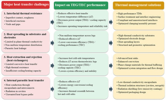
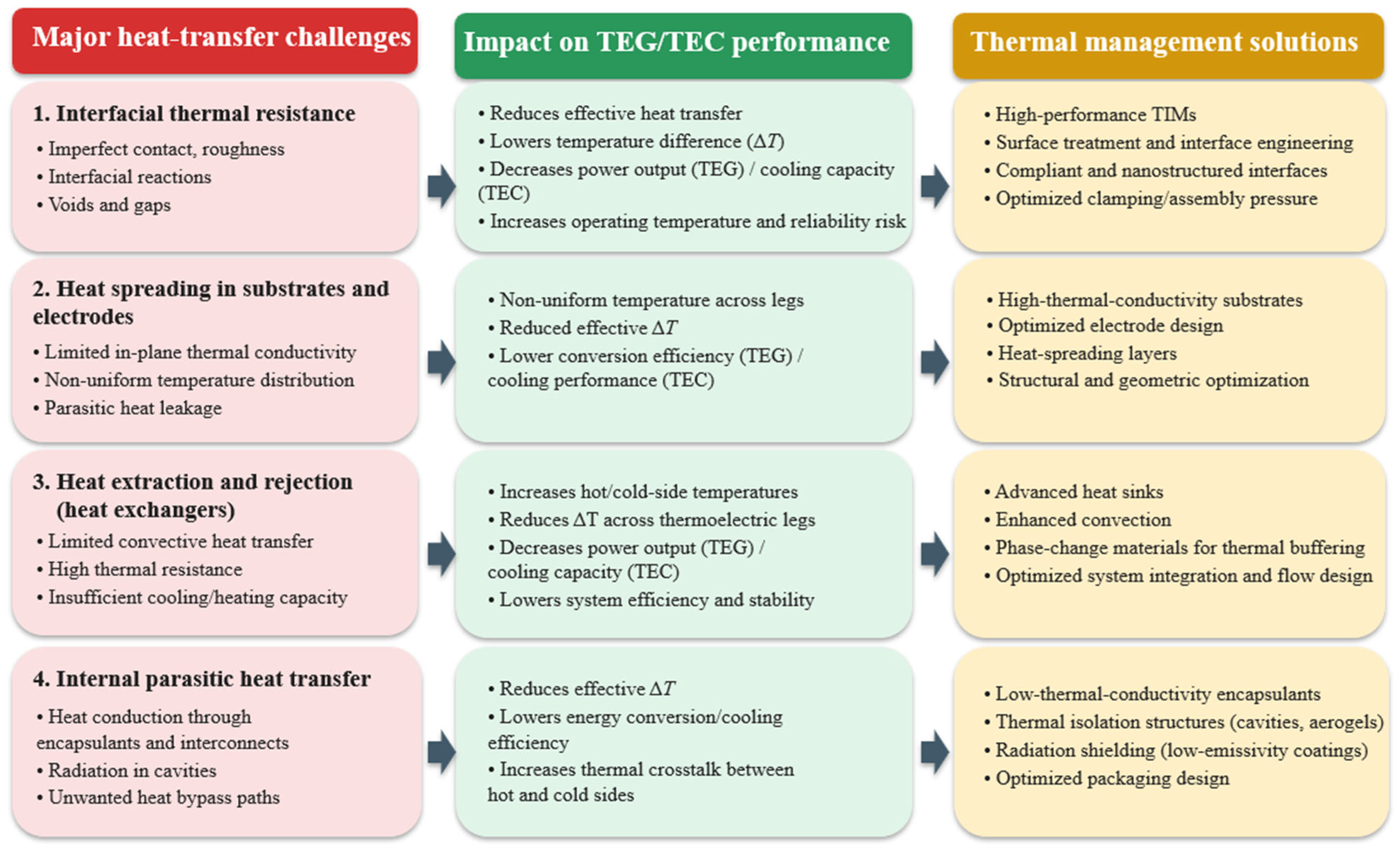
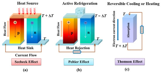
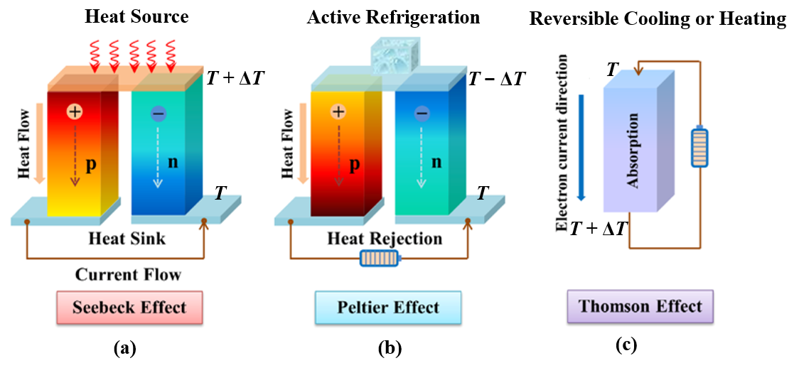
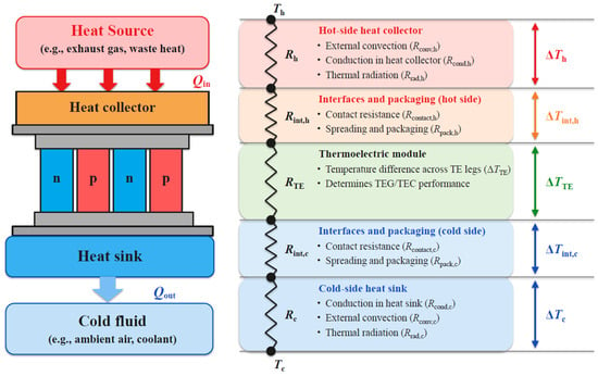
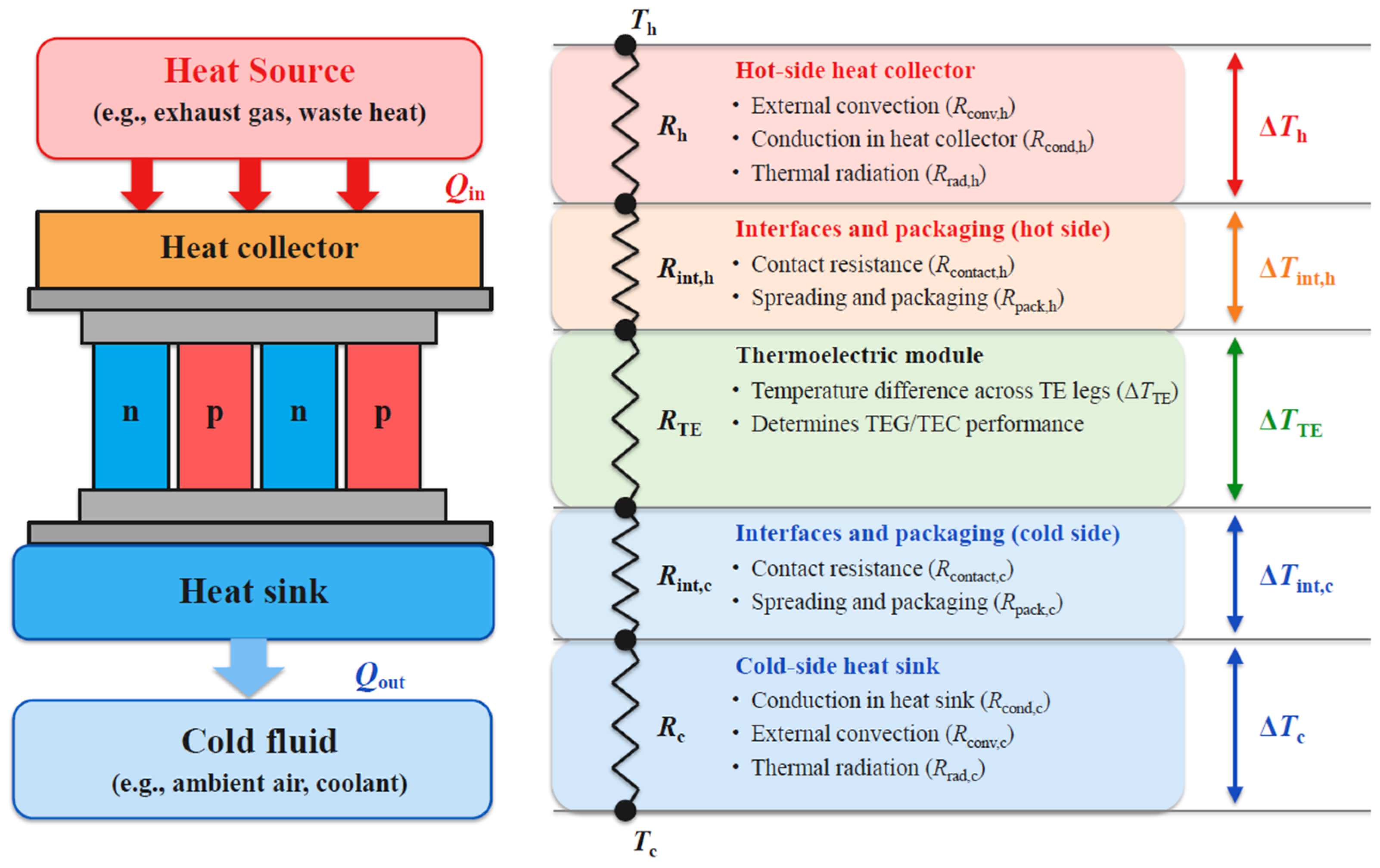
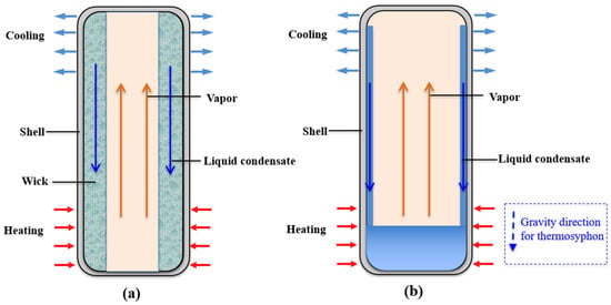
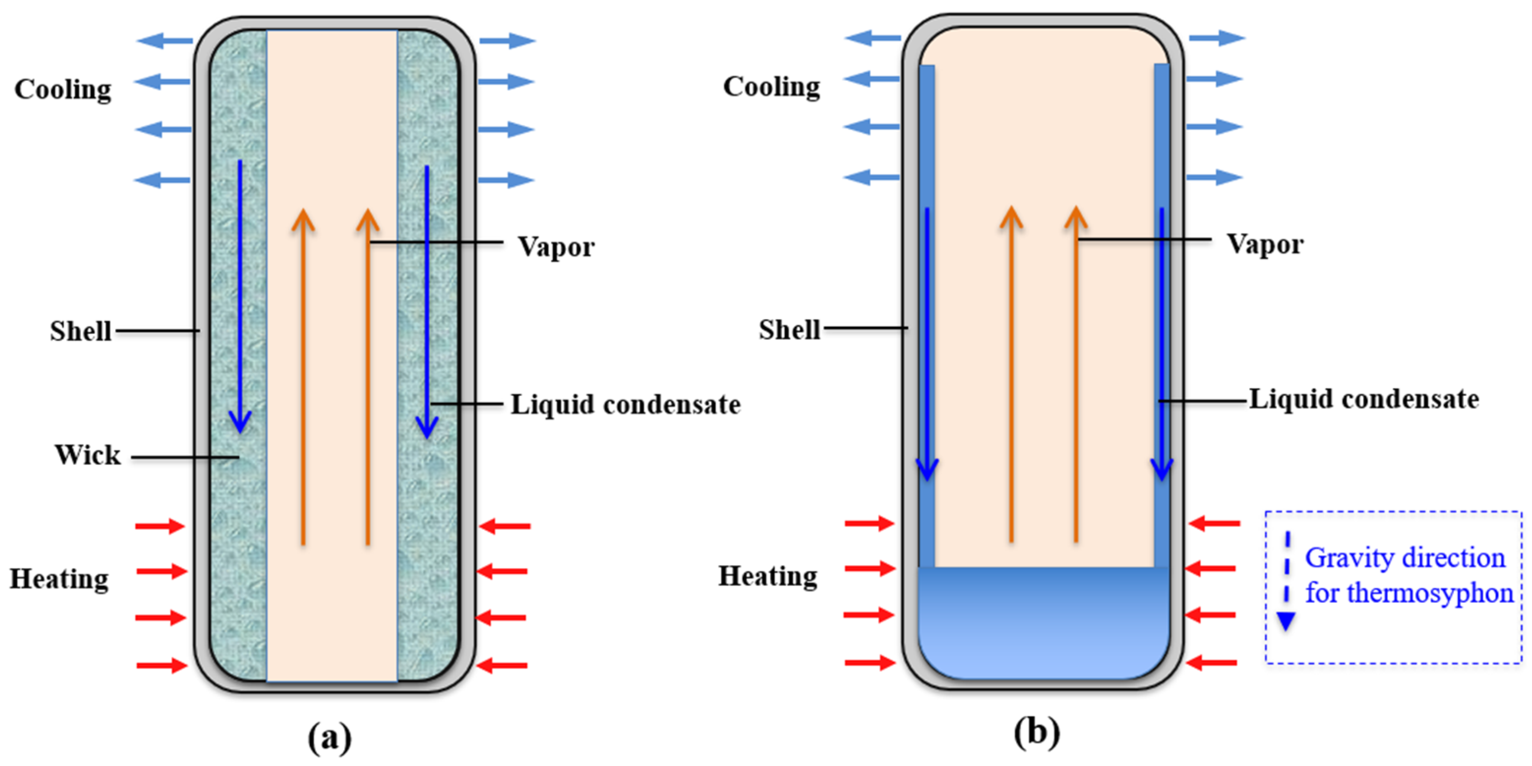
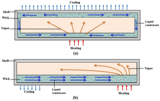
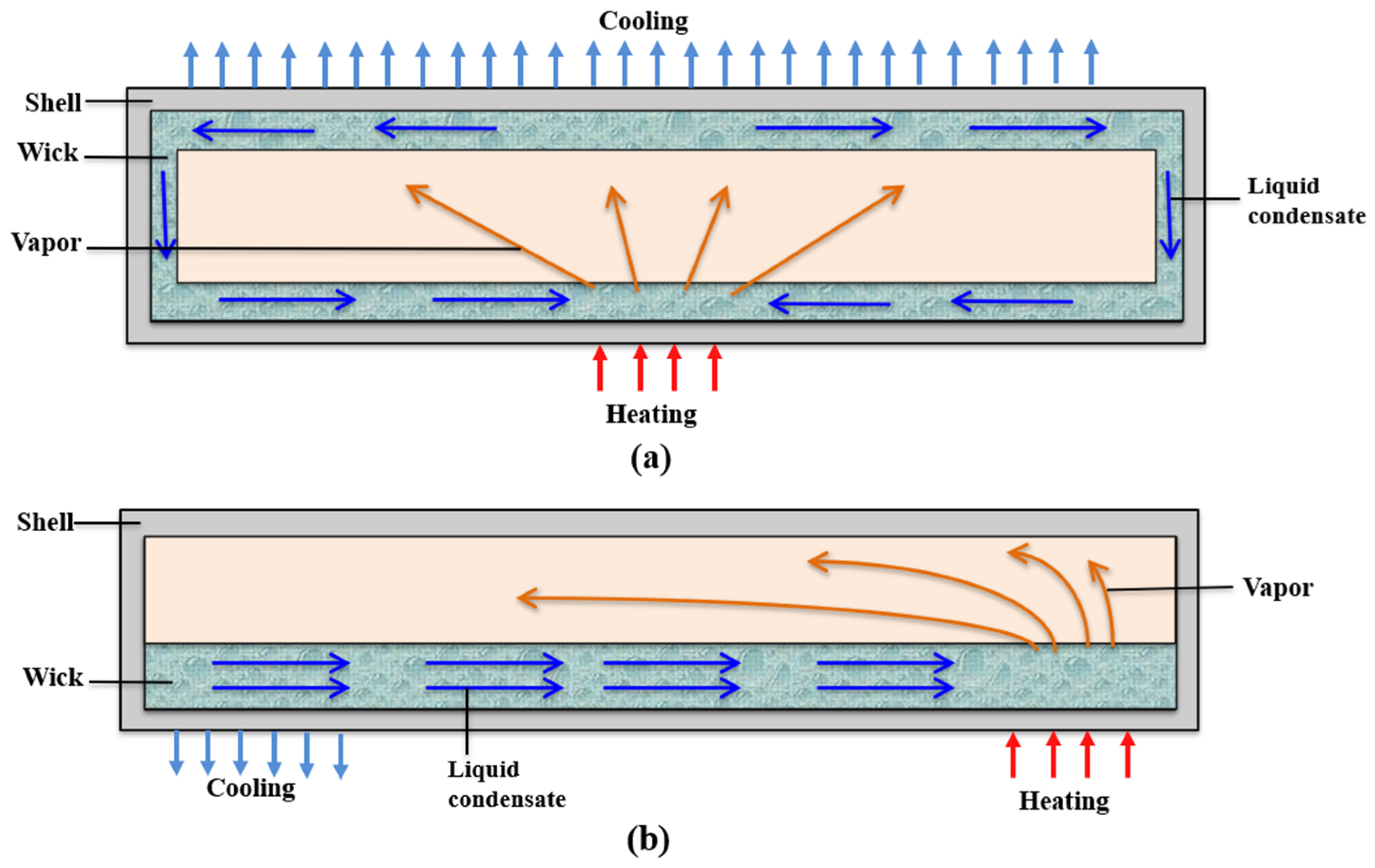

Disclaimer/Publisher’s Note: The statements, opinions and data contained in all publications are solely those of the individual author(s) and contributor(s) and not of MDPI and/or the editor(s). MDPI and/or the editor(s) disclaim responsibility for any injury to people or property resulting from any ideas, methods, instructions or products referred to in the content. |
© 2026 by the authors. Licensee MDPI, Basel, Switzerland. This article is an open access article distributed under the terms and conditions of the Creative Commons Attribution (CC BY) license.