


Abstract
Coal mine dust is a critical hazard that can trigger explosions and cause pneumoconiosis, thereby severely threatening mine safety and occupational health. Although long-forcing and short-exhausting ventilation are commonly adopted in long-distance heading faces, their parameters are often determined empirically, leading to suboptimal dust control efficiency. This study utilizes numerical simulations via FLUENT to investigate dust migration patterns under five key ventilation parameters in the 2-2 Upper Coal Working Face of the Xintai Taigemiao Mining Area. The results reveal a zonal distribution of dust: a high-concentration accumulation zone within 0–15 m, a medium-concentration transition zone between 15 and 35 m, and a low-concentration settling zone beyond 35 m. Diffusion rates vary significantly across zones under different ventilation settings. The optimized parameters for the 20 m2 cross-section roadway in this study include: exhausting duct set 0.3 m from the return-side wall, exhausting inlet at a distance of 4 m (0.9√A, A is the roadway cross-sectional area) from the face, forcing inlet at 20 m (4.5√A) from the face, duct installation height of 0.75 times the roadway height, and a forcing-to-exhausting air volume ratio between 1.2 and 1.6. Compared with the non-optimized scheme, this configuration reduces the average dust concentration in the breathing zone (1.2 m height) by up to 62.3%, and restricts 85% of the high-concentration dust within 0–15 m from the heading face, effectively suppressing dust dispersion to the rear roadway. This study provides a quantitative reference and theoretical strategy for engineering applications of dust prevention in similar large-section long-distance heading faces within the scope of numerical simulation.
1. Introduction
As a core component of China’s energy system, coal continues to maintain its dominant position. According to data from the National Bureau of Statistics of China, in 2024, China’s raw coal production reached a record high, with the output from industrial enterprises above a designated size reaching 4.76 billion tons, an increase of 1.3% over the previous year [1]. It is predicted that domestic coal production and sales will continue to grow in 2025. With the advancement of high-yield and high-efficiency mining, the mechanization rate of China’s coal mining has exceeded 99%, and the proportion of intelligent production capacity has surpassed 50%. However, dust pollution during production remains a key bottleneck restricting the high-quality development of the industry.
Coal mining is primarily conducted underground, with limited operational space, leading to the generation of large amounts of dust that is difficult to disperse. Dust hazards exhibit multi-dimensional characteristics, particularly fine particles that remain suspended in roadway air for long periods, posing significant threats to coal mine safety and the occupational health of frontline workers. Inhalation of respirable dust leads to irreversible pulmonary fibrosis and incurable respiratory impairment [2]. In recent decades, new cases of coal worker pneumoconiosis have accounted for over 60% of annual occupational disease additions in China, and in recent years, this proportion has even reached 80%. The number of deaths caused by pneumoconiosis far exceeds that from coal mine production accidents [3]. Meanwhile, the risk of explosion increases dramatically when suspended dust mixes with gas—respirable dust particles below 5 microns, accounting for over 30% of total dust, have a lower explosion concentration threshold, further escalating underground safety risks. Additionally, dust accelerates equipment wear, interferes with sensor performance, and hinders the application of intelligent mining technologies. Suspended dust is generated in all underground operations, among which the heading face has the most complex airflow–dust coupling environment and the highest dust control difficulty [4]. Investigations show that without dust control measures, peak dust concentration at a heading face can exceed 6000 mg/m3, with respirable dust accounting for 40% [5]. Therefore, effectively controlling dust diffusion at the heading face and reducing dust hazards are crucial for protecting the health of coal miners and promoting the sustainable development of the coal industry.
In a coal mine roadway heading face, ventilation methods such as forcing ventilation, exhausting ventilation, and long-forcing and short-exhausting ventilation are commonly used for dust control. Forcing ventilation is widely adopted due to its simple equipment and high safety, but its airflow diffusion range is limited, making it difficult to control dust diffusion on long-distance roadways. Exhausting ventilation can quickly exhaust dust but carries a risk of gas accumulation, only suitable for low-gas mines. Consequently, for long-distance headings in high-yield mines, single forcing or exhausting ventilation often fails to achieve dust control effects, making long-forcing and short-exhausting ventilation the preferred solution for large-section, long-distance heading roadways [6]. This method provides fresh air through a forcing duct and creates a local negative pressure zone via a short exhausting duct, confining dust within a controllable range for directional exhaust and effectively solving the problem of secondary dust resuspension in the eddy current zone of forcing ventilation. In this forcing-dominated, exhausting-assisted ventilation mode, ventilation parameters become critical factors affecting dust control efficiency.
Yu et al. [7] established a high-fidelity 3D model of a heading roadway and developed a CFD-DEM airflow–dust coupling simulation method based on the turbulence model and Hertz–Mindlin model to study dust concentration distribution and deposition characteristics of different particle sizes in a fully mechanized heading face under mixed forcing–exhausting ventilation. Hua et al. [8] used CFD combined with field measurement to study the dust extraction effect of a wind curtain in a rock tunnel heading face with long-forcing and short-exhausting ventilation. Zhou et al. [9] compared and analyzed dust control effects under four ventilation parameters—distance between the forcing inlet and the heading face, distance between the exhausting inlet and the heading face, exhausting–forcing air volume ratio, and duct height—using gas–solid two-phase flow theory. Nie et al. [10] innovatively applied orthogonal test methods based on numerical simulation to study the influence of four ventilation parameters (distance between the forcing inlet and the heading face, distance between the exhausting inlet and the heading face, forcing air volume, and exhausting air volume) on dust control, ranking their effects on different dust concentrations to determine the optimal dust control scheme. Wen et al. [11] studied how to determine the relative positions of forcing and exhausting ducts and the reasonable forcing–exhausting ratio for long-forcing and short-exhausting ventilation in long-distance, large-section roadways (heading face area of 25 m2). However, dust migration characteristics in a heading face are influenced by multiple factors, including coal seam occurrence conditions, mining technology, roadway dimensions, duct layout, air volume regulation, and forcing–exhausting ratio. Therefore, studying dust migration characteristics in combination with specific coal seam conditions and engineering realities of mining areas is of greater practical significance for improving dust control efficiency of long-forcing and short-exhausting ventilation in the heading face.
In recent years, with the development of intelligent mining technology, the intelligent collaborative control of ventilation and dust suppression based on real-time dust concentration sensing has become a research hotspot. Relevant studies have realized the dynamic adjustment of ventilation parameters through the fusion of dust concentration monitoring data and CFD simulation, which provides a new idea for the precise control of dust in the heading face. Although existing studies have clarified the influence of ventilation parameters on dust migration, three core research gaps remain: (1) Most models adopt idealized geometry, ignoring the airflow obstruction caused by roadheaders, belt conveyors and other actual equipment, lacking coupled analysis with on-site equipment layout and geological conditions [9]. (2) Existing research mostly focuses on the qualitative law of single parameters, lacking quantitative multi-parameter collaborative optimization criteria for specific mining conditions. (3) Intelligent optimization methods for multi-parameter matching have been widely used in coal mining systems, e.g., intelligent deployment for coal and coalbed methane coupling coordinated exploitation [12], but few are applied to the intelligent collaborative dynamic control of ventilation dust control in the heading face [13].
To fill the above research gaps, this paper takes the 2-2 Upper Coal Working Face in the Xintai Taigemiao Mining Area as the engineering prototype, fully considers the actual equipment layout and roadway geometric conditions, and constructs a full-scale 3D numerical model of dust migration in the heading face based on gas–solid two-phase flow theory. Five key ventilation parameters that directly affect dust control efficiency are selected: the distance between the exhausting duct and the return-air side wall, the distance between the exhausting inlet and the heading face, the distance between the forcing inlet and the heading face, the installation height of the ducts, and the forcing-to-exhausting air volume ratio. Through single-factor numerical simulation experiments, the influence law of each parameter on dust migration zoning characteristics and breathing zone concentration is systematically analyzed, and the multi-parameter collaborative optimization scheme suitable for the study mine is proposed. The results are expected to provide effective quantitative references for the layout of ventilation and dust control systems in similar large-section long-distance heading faces, and provide theoretical support for reducing occupational health risks of underground workers.
2. Numerical Model Construction
2.1. Mathematical Model
The study of airflow and dust migration characteristics in heading roadways falls within the scope of gas–solid two-phase flow dynamics [14]. This paper combines the Euler–Lagrange method with the discrete phase model (DPM), treating gas as the continuous phase [15] and solid particles as the discrete phase. The continuous-phase flow field is first solved in a steady state using the continuity equation, momentum equation, and turbulence equations, after which the discrete phase model is used to track the migration trajectories of dust particles in Lagrangian coordinates.
Continuity equation:
Momentum equation:
where ρ is the gas density (kg/m3); t is time (s); u is the gas velocity vector (m/s); μ is the laminar viscosity coefficient (Pa·s); and ut is the turbulent viscosity coefficient (Pa·s).
In turbulent flow, turbulent kinetic energy (k) and turbulent dissipation rate (ε) are two core parameters describing the turbulent process, so the standard k − ε equation model is commonly used for the turbulence model [16]. When the influence of molecular viscosity is ignored, the standard k − ε model is more accurate than other high Reynolds number turbulence models [17].
Realizable k − ε equations:
where Gk is the turbulent kinetic energy term generated by the mean velocity gradient (kg/(s3·m)); Gb is the turbulent kinetic energy due to buoyancy (kg/(s3·m)); and c1ε, c2ε, c3ε, σk, σε are model constants, taking values 1.44, 1.92, 0.09, 1.00, and 1.3 respectively [18].
To accurately predict the trajectories of dust particles, referencing previous studies [19], forces including drag, gravity, buoyancy, pressure gradient force, and Saffman force are considered. Under the condition of neglecting collisions between dust particles, the motion equation for a single dust particle is established according to Newton’s second law. This assumption is applicable to dilute gas–solid two-phase flow; for the high-concentration dust accumulation zone (0–15 m from the heading face) in this study, the neglected particle–particle collision and agglomeration effect may accelerate dust settling, leading to a slight overestimation of suspended dust concentration in the simulation results. This limitation will be further discussed in the subsequent section.
where mp is the mass of the dust particle (kg); the velocity of the dust particle is given in (m/s); and Fd, Fg, Fp, Fs are the drag force, gravity and buoyancy force, pressure gradient force, and Saffman force acting on the dust particle, respectively (N).
Among all the forces, the drag force has the most significant influence on the particle motion trajectory [20]. Assuming the dust particle is a rigid sphere, the drag force Fd satisfies the spherical drag characteristics described by Equation (6):
where dp is the diameter of the dust particle (m); Cd is the drag coefficient; a1, a2, a3 are constants; and Re is the Reynolds number.
All simulations were performed in ANSYS FLUENT 2021 R2 with a pressure-based solver. For steady flow field calculation, the SIMPLE algorithm was used for pressure-velocity coupling, and the second-order upwind scheme was adopted for discretization of momentum, k and ε equations. The convergence thresholds were set to 10−6 for the continuity equation and 10−5 for momentum, k and ε equations; calculation was considered converged when residuals fell below thresholds and the monitored cross-sectional average air velocity stabilized (≈1500 iterations).
For transient dust migration calculation, the DPM was enabled after steady flow field convergence. The first-order implicit scheme was used for time discretization, with a time step of 0.1 s (determined to ensure the maximum particle migration distance per step was less than the minimum grid size). Each time step was iterated 20 times, with a total simulation time of 30 s to reach a dynamic equilibrium of dust distribution.
2.2. Physical Model and Boundary Conditions
Taking the 2-2 Upper Coal Working Face in the Xintai Taigemiao Mining Area as the foundational prototype, a comprehensive 3D geometric model of the heading face was constructed. Using SpaceClaim, Ansys’s built-in geometry software, the model was strictly based on actual roadway dimensions, spatial layout, and equipment configuration. To optimize the computational workload and reduce meshing complexity while ensuring simulation accuracy, appropriate geometrical simplifications were made, such as neglecting minor structural protrusions and small-scale secondary equipment.
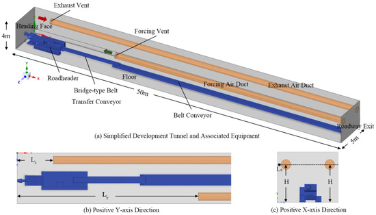
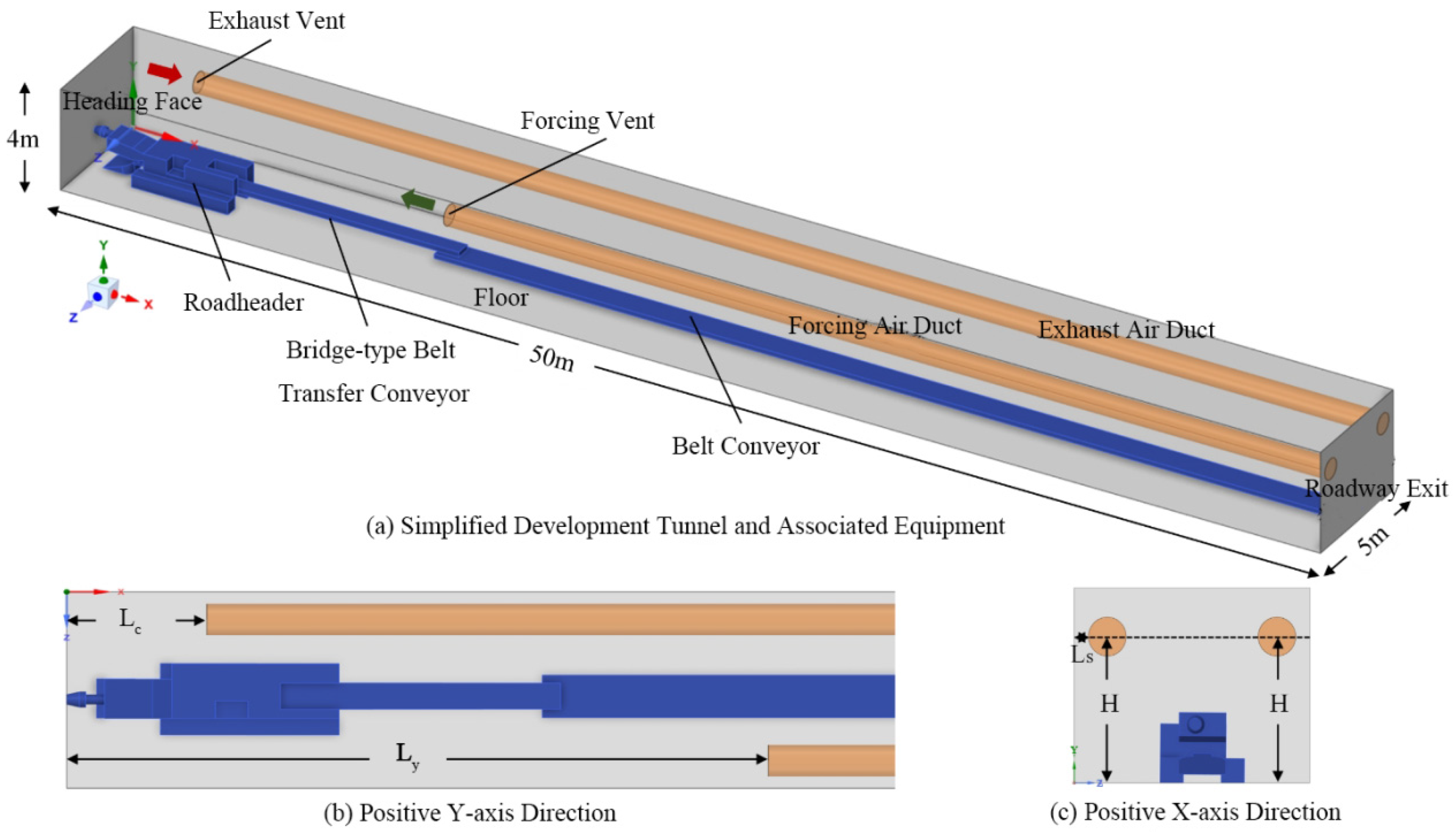
The established 3D physical model, illustrated in Figure 1a, encompasses six core components critical to the excavation and ventilation processes: the roadway, roadheader, loader, conveyor belt, forcing air duct, and exhausting duct. A standard Cartesian coordinate system was established: the positive X-direction points longitudinally from the heading face toward the roadway exit, the positive Y-direction points vertically from the floor to the roof, and the positive Z-direction points horizontally from the return air side to the forcing air side.
Figure 1.
Physical model of long-forcing and short-exhausting ventilation for the heading face.
Furthermore, Figure 1b,c detail crucial spatial parameters that directly influence the airflow field and dust capture efficiency: the distance Lc between the exhausting inlet and the heading face, the distance Ly between the forcing inlet and the heading face, the lateral distance Ls between the exhausting duct and the return-air side wall, and the duct installation height H. Specific dimensional information for these variables is systematically listed in Table 1.
Table 1.
Parameters of the heading face physical model.
In the numerical simulation of roadway dust dispersion, accurately defining the fluid computational domain is a critical prerequisite for ensuring the reliability and rationality of simulation results. Specifically, the computational domain is defined as the continuous internal space of the roadway, which covers the entire hollow area accessible to air and dust particles. It explicitly excludes solid volumes occupied by key equipment, such as roadheaders (the core excavation machinery), various transport machinery, and ventilation ducts. These solid components are treated as impermeable boundaries in the numerical model, which is not only consistent with the actual physical environment of the roadway but also aligns with the boundary setting criteria specified in Table 2.
Table 2.
Boundary condition settings for the physical model.
To optimize the allocation of computational resources and ensure simulation efficiency, the research focuses on dust dispersion dynamics in the main working area of the roadway. This area is the key region where dust is generated (mainly from roadheader cutting) and where it directly endangers the health of on-site operators. Therefore, the migration and settlement processes of dust particles inside the exhausting duct after being captured by the ventilation system are not considered. This reasonable simplification helps concentrate limited computing power on the core research object, ensuring the simulation can accurately capture complex dust dispersion behaviors in the working area, which is also aligned with the focus of boundary parameters listed in Table 2.
Finally, the accurate boundary conditions required for simulation initialization are fully detailed in Table 2. These conditions are essential for reproducing the actual flow field and dust dispersion environment in the roadway, including key parameters such as ventilation inlet velocity, dust source strength, roadway wall roughness, and exhausting outlet pressure. These parameters closely link the computational domain definition, simulation focus, and actual engineering conditions, effectively avoiding deviations between the simulation and real scenarios and laying a solid foundation for obtaining scientific and credible simulation results.
The turbulence intensities of the forcing duct inlet (3.07%) and exhausting duct inlet (3.15%) are calculated according to the empirical formula for fully developed turbulent flow in circular pipes:
where Re is the Reynolds number of the airflow at the duct inlet, calculated based on the duct diameter (0.8 m), inlet air velocity, and air kinematic viscosity. The calculated values are rounded to two decimal places, which are consistent with the turbulence intensity setting range of mine ventilation numerical simulation in existing studies [9,14].
The dust release mass flow rate (0.002 kg·s−1) is derived from the field measured data of the 2-2 Upper Coal Working Face in the Xintai Taigemiao Mining Area, converted according to the actual dust production rate of the roadheader during normal cutting. The X-direction velocity of dust particles (1 m/s) is set according to the initial velocity of dust generated by roadheader coal cutting, which is consistent with the setting range in existing similar studies [7,15].
To balance simulation accuracy and computational efficiency, the following reasonable assumptions are made in this model: The migration of dust particles inside the exhausting duct after capture is not considered, and the research focus is on the dust dispersion law in the main working area of the roadway where operators are located. The roadway wall and equipment surfaces are set as rigid boundaries, and the deformation of the roadway during excavation is not considered. The influence of temperature and humidity changes on airflow and dust migration is ignored. The above assumptions may lead to a certain deviation between the simulation results and the actual on-site situation, and the specific influence will be discussed in Section 5.
2.3. Mesh Generation and Grid Independence Verification
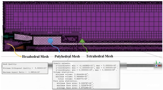
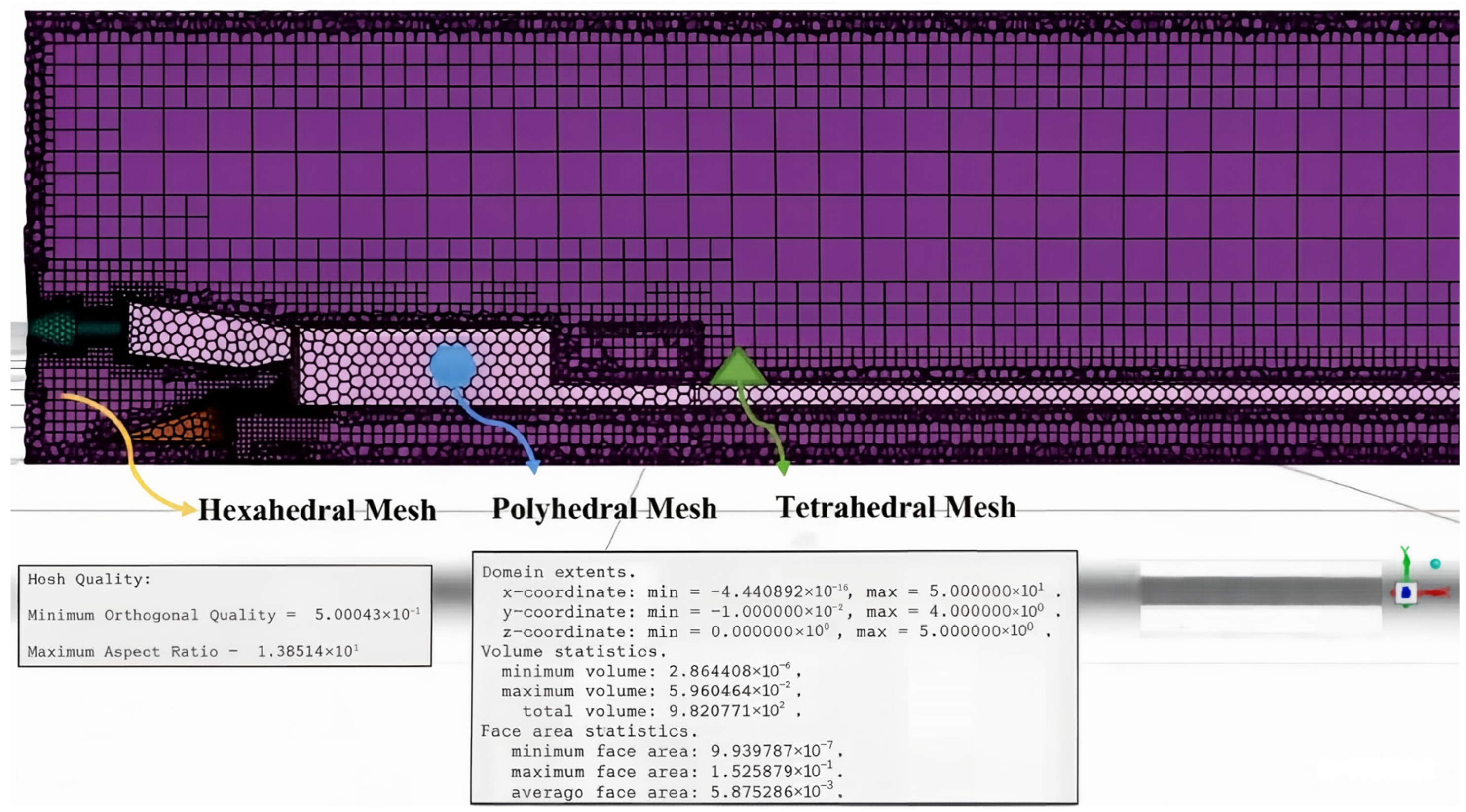
The physical model mesh of the heading face was generated in Fluent Meshing to discretize the fluid domain and capture complex airflow and dust diffusion. Considering the complex geometry of excavation equipment and strong turbulence regions, a reliable meshing strategy was adopted. Local mesh refinement was applied to key areas with large velocity and concentration gradients, mainly near the roadheader, duct inlets, and the heading face, balancing accuracy and computational efficiency. The overall mesh and refined regions are shown in Figure 2.
Figure 2.
Detailed mesh generation and quality distribution of the airflow field in the heading face.
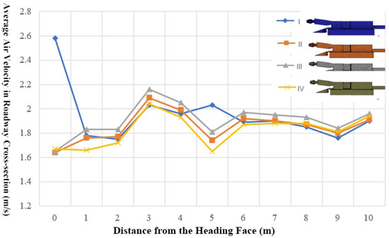
To obtain more accurate numerical simulation results, grid independence verification was performed using four grids (I–IV) of varying densities for the heading face model. Their maximum sizes were 0.15, 0.10, 0.08, and 0.05 m, with a uniform minimum size of 0.048 m (Figure 3). Two core indicators were selected for verification: the average air velocity at roadway cross-sections (the basis of flow field calculation) and the average dust concentration at the breathing zone height (Y = 1.2 m, the core outcome of this study). The verification results show that the four grids yielded similar airflow velocity distributions, with the relative error of average velocity between Grid II and Grid IV being less than 2.1%; meanwhile, the relative error of average breathing zone dust concentration between Grid II and Grid IV was less than 3.4%, both within the acceptable range of the engineering simulation. It shows that the grid density has negligible influence on the simulation outcomes when the maximum grid size is less than 0.10 m. For efficient computing resource use, Grid II was adopted in this study.
Figure 3.
Comparison of air velocity at roadway cross-sections with different grid densities.
2.4. Simulation Scheme Design for Ventilation Parameter Optimization
To improve the dust control effect of long-forcing and short-exhausting ventilation in the heading face, this study selected five key ventilation parameters including duct layout, air volume ratio and installation height, and designed 11 single-factor simulation schemes within reasonable engineering ranges. The single-factor method was adopted to ensure that only one parameter was changed in each scheme, and the other parameters remained consistent with the baseline scheme (Scheme 1), so as to quantitatively analyze the independent influence of each parameter on dust migration. The specific parameter settings of all schemes are listed in Table 3.
Table 3.
Simulation schemes for dust migration characteristics and ventilation conditions in heading face with long-forcing and short-exhausting ventilation.
The optimization criteria for ventilation parameters are determined as follows: (1) The average dust concentration in the breathing zone (Y = 1.2 m) is minimized. (2) The high-concentration dust is restricted as much as possible to within 0–15 m from the heading face, to avoid dust diffusion to the rear roadway where operators are active. (3) The airflow velocity in the roadway meets the requirements of the Coal Mine Safety Regulations (≥0.25 m/s). By comparing the dust control effects under different schemes according to the above criteria, the optimal ventilation scheme matching the project was determined. Each scheme varies in at least one parameter, ensuring the validity and comparability of the simulation results.
3. Numerical Simulation Results
This chapter presents the numerical simulation results of the airflow field and dust migration characteristics under the long-forcing and short-exhausting ventilation system, and reveals the spatiotemporal evolution law of dust in the heading roadway.
3.1. Airflow Field Distribution Characteristics
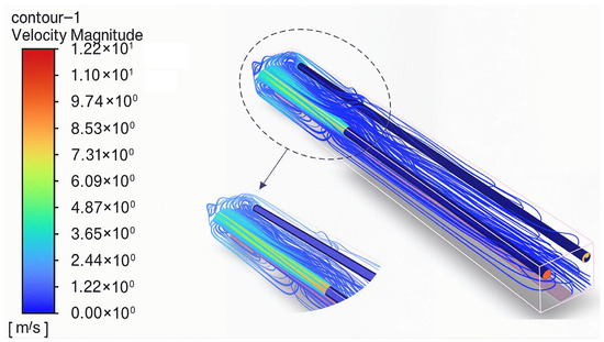
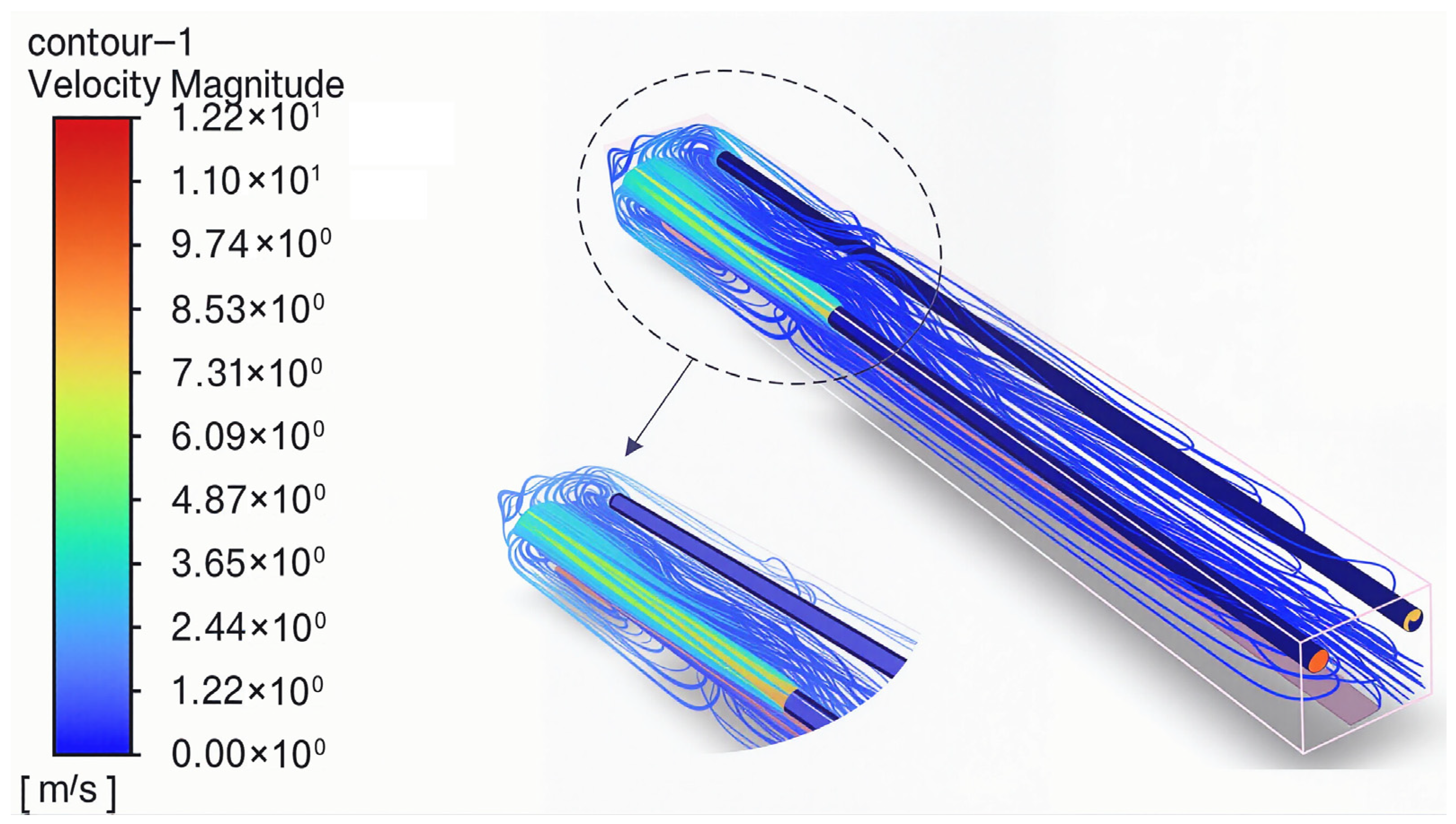
Based on the numerical model and Simulation Scheme 1, the airflow field in the heading roadway was calculated (Figure 4). The results indicate a complex, chaotic flow field near the heading face and between the ducts, which gradually stabilizes as the distance from the face increases. Consequently, velocity vector diagrams at various heights were extracted to analyze the localized flow distribution.
Figure 4.
Streamline distribution in the heading face.
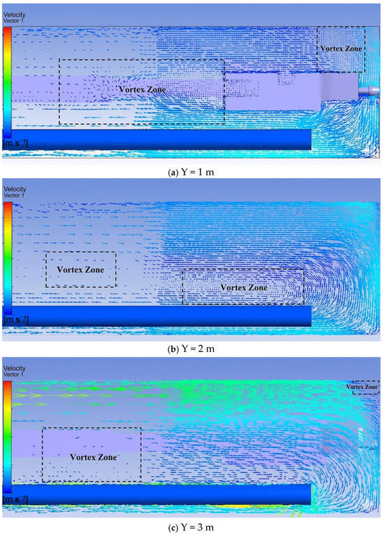
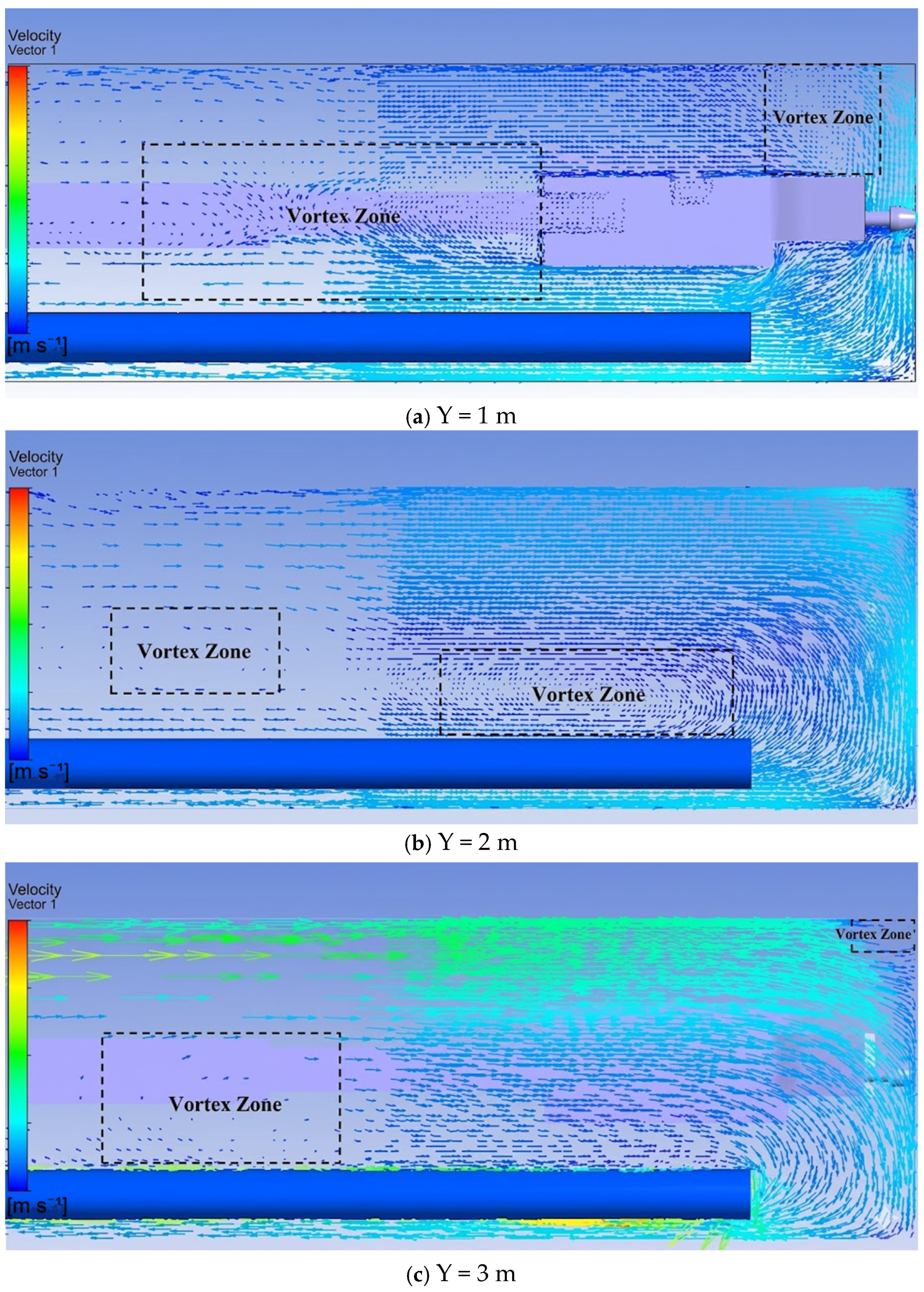
As shown in Figure 5a, at the horizontal plane 1 m above the floor, obvious vortices are mainly distributed at the tail of the roadheader and on the left inlet air side, which directly affect the local airflow stability. Figure 5b presents the flow field at 2 m above the floor, where vortices mainly appear farther from the roadheader tail and close to the wall of the front exhausting duct, showing a gradual outward migration with height. As observed in Figure 5c, for the plane 3 m above the floor, vortices are concentrated near the exhausting duct wall behind the roadheader and at the junction between the inlet air side rib and the heading face. In addition, the figures reveal that recirculating flow mainly exists in the breathing zone (y = 1 m) and lower regions on the exhausting duct side, which is highly relevant to on-site dust accumulation and occupational health risks.
Figure 5.
Air velocity vector distribution in X–Z cross-sections at different heights from the floor.
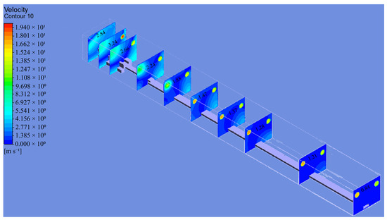
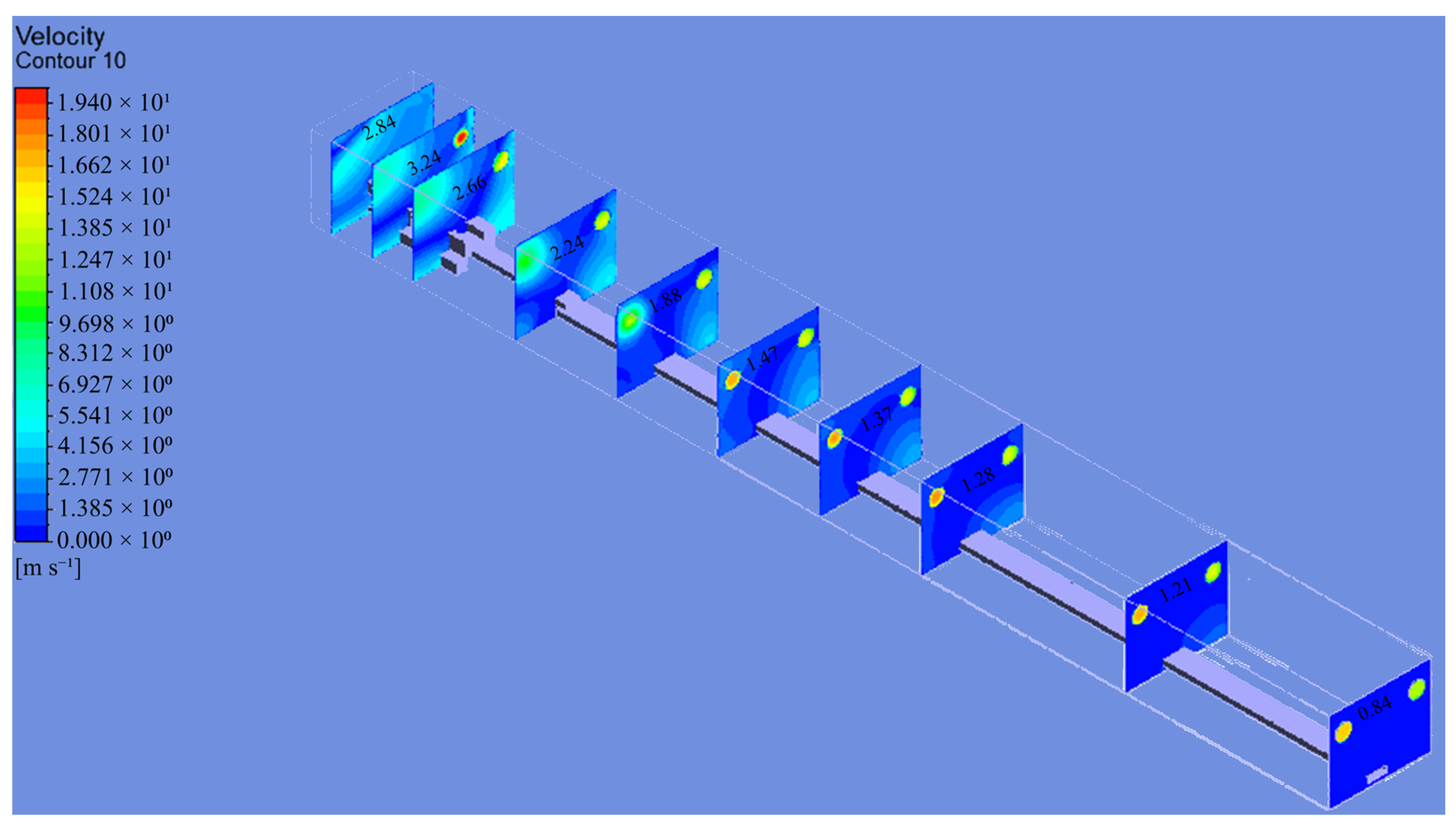
Based on the simulation results, the velocity contours along the X-axis at various roadway locations were obtained, as shown in Figure 6. According to Figure 6, the following observations can be made: (1) Within 0–10 m from the heading face, the flow field contains numerous vortices, and the air velocity contour shows significant variations. (2) The airflow velocity in the roadway gradually decreases from the inlet to the outlet of the forcing duct, and further attenuates at the heading face. Although the air velocity at the heading face is much lower than that at the forcing duct inlet, it still exceeds 0.25 m/s, complying with the regulations of the Coal Mine Safety Regulations for the air velocity in heading roadways. (3) From the inlet to the outlet of the forcing duct, the jet flow changes uniformly around the duct axis, but from the duct outlet to the heading face, the velocity no longer changes uniformly around this axis. (4) At a distance of 5 m from the forcing duct outlet (X = 10 m), the cross-sectional airflow field of the ventilation jet in the roadway approximates a semicircle. After the jet flows to X = 10 m, due to boundary layer development and turbulent entrainment, the jet continues to entrain ambient air, forming a mixture of the original jet air and ambient air. Meanwhile, the cross-section of the ventilation jet begins to gradually contract and move forward, and the shape of the air velocity contour in the jet cross-section evolves into a partial circle. (5) As the cross-section of the ventilation jet continues to contract, it moves forward until it forms an impinging attached jet flow upon reaching the heading face. However, as the airflow progresses, the jet gradually dissipates, and the airflow begins to recirculate.
Figure 6.
Air velocity distribution in Y–Z cross-sections at different distances from the heading face.
3.2. Dust Flow Field Distribution Characteristics
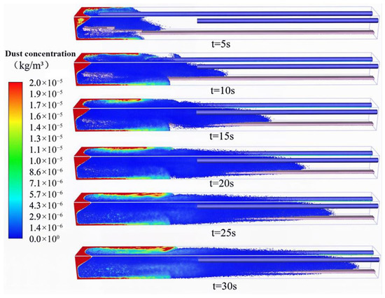
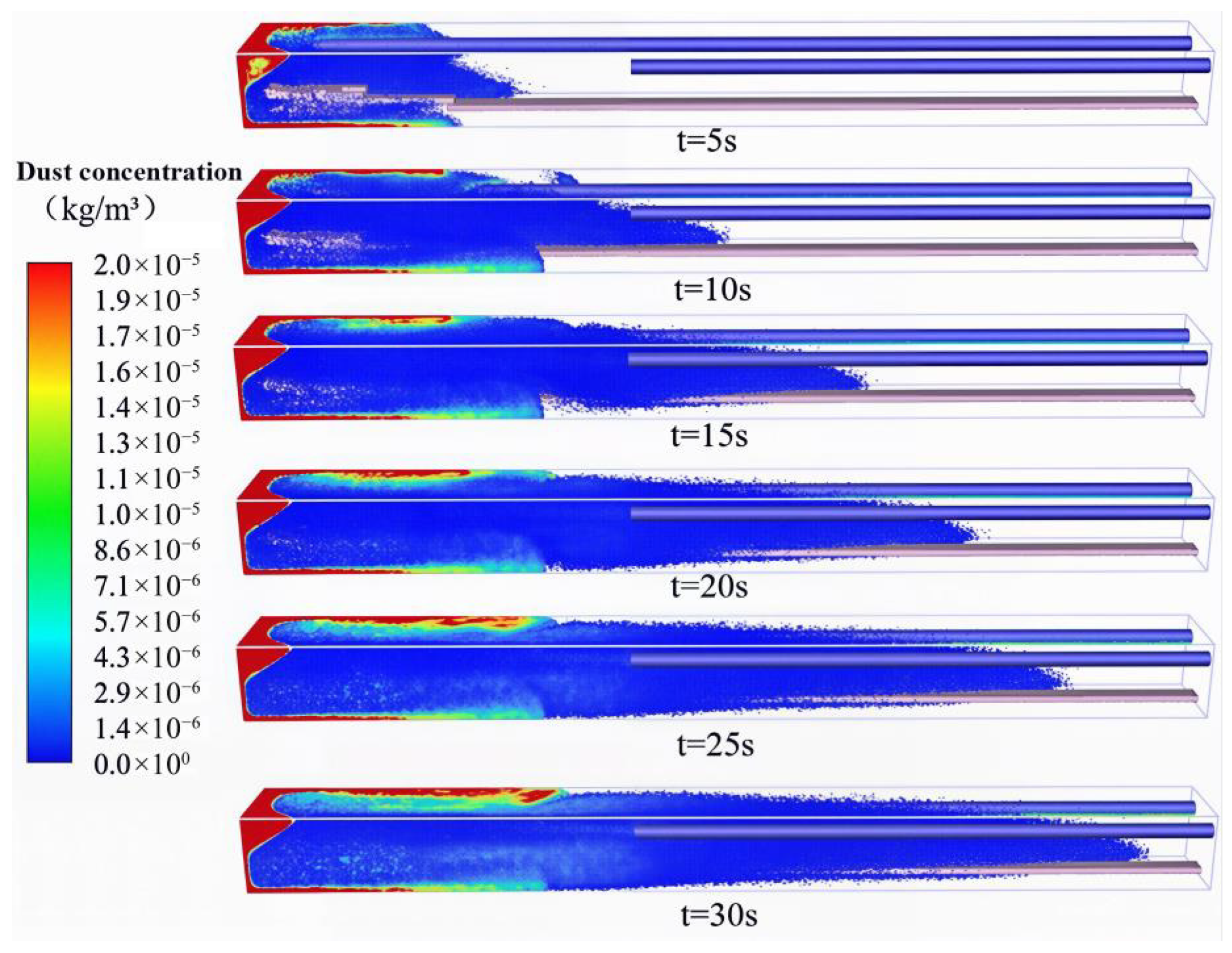
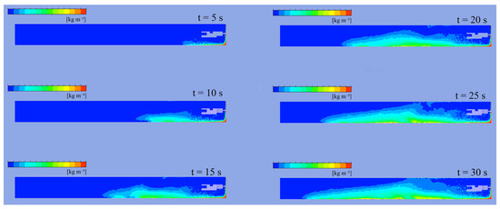
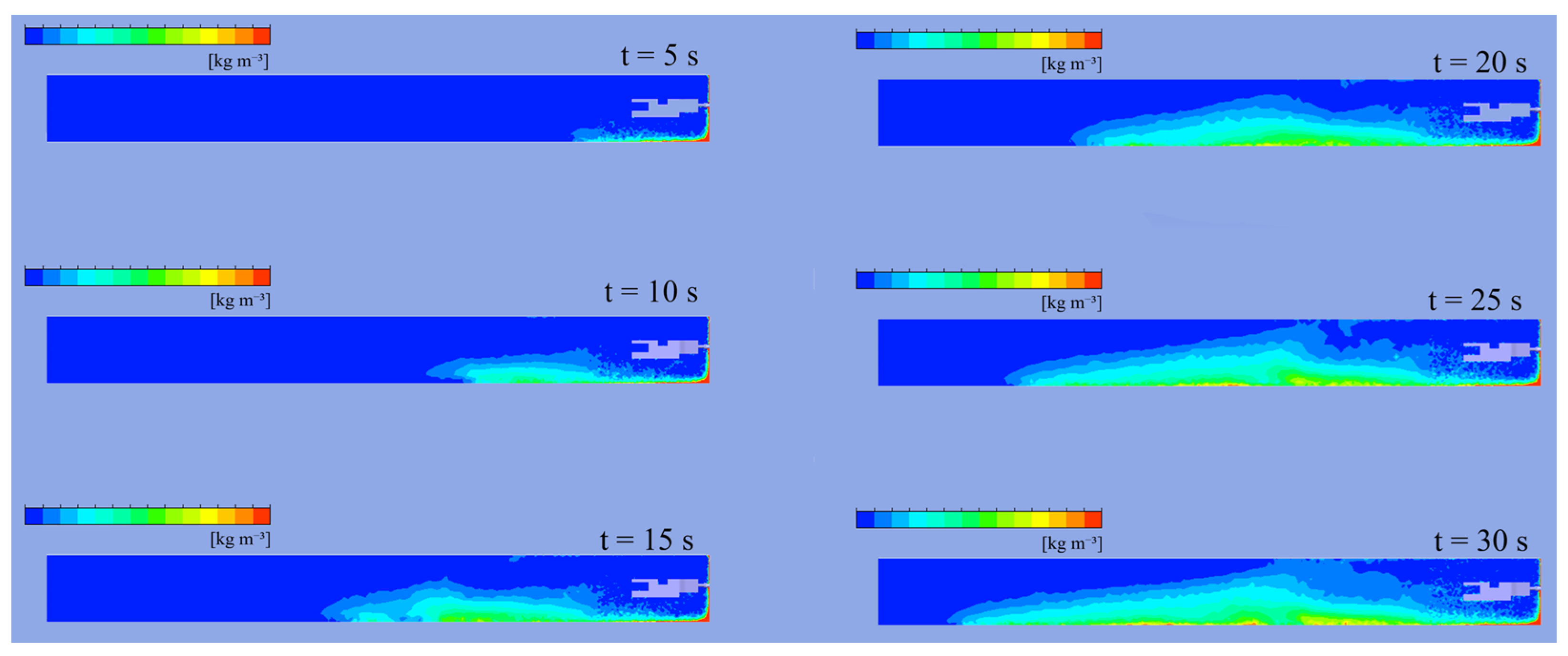
Based on the above airflow field distribution characteristics, further research was conducted on the dust flow distribution patterns. Figure 7 illustrates the migration behavior of dust in the roadway at different durations of cutting. Dust generated by the roadheader cutting process primarily converges toward the exhausting inlet under the negative pressure suction of the exhausting duct. A portion of the dust not inhaled by the exhausting duct adheres to the duct and moves backward, causing the dust concentration on the return air side in the front half of the roadway to be significantly higher than that on the inlet air side.
Figure 7.
Spatiotemporal patterns of dust migration in the heading roadway.
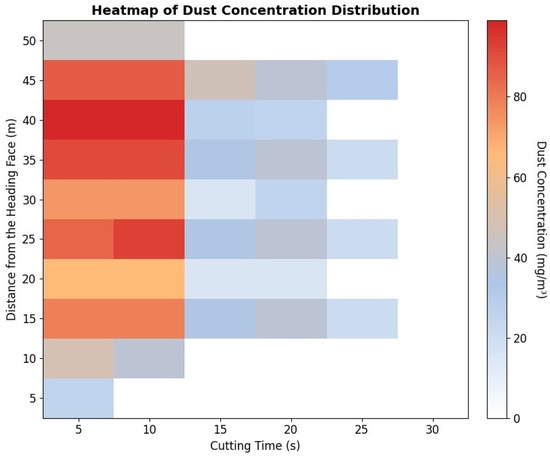
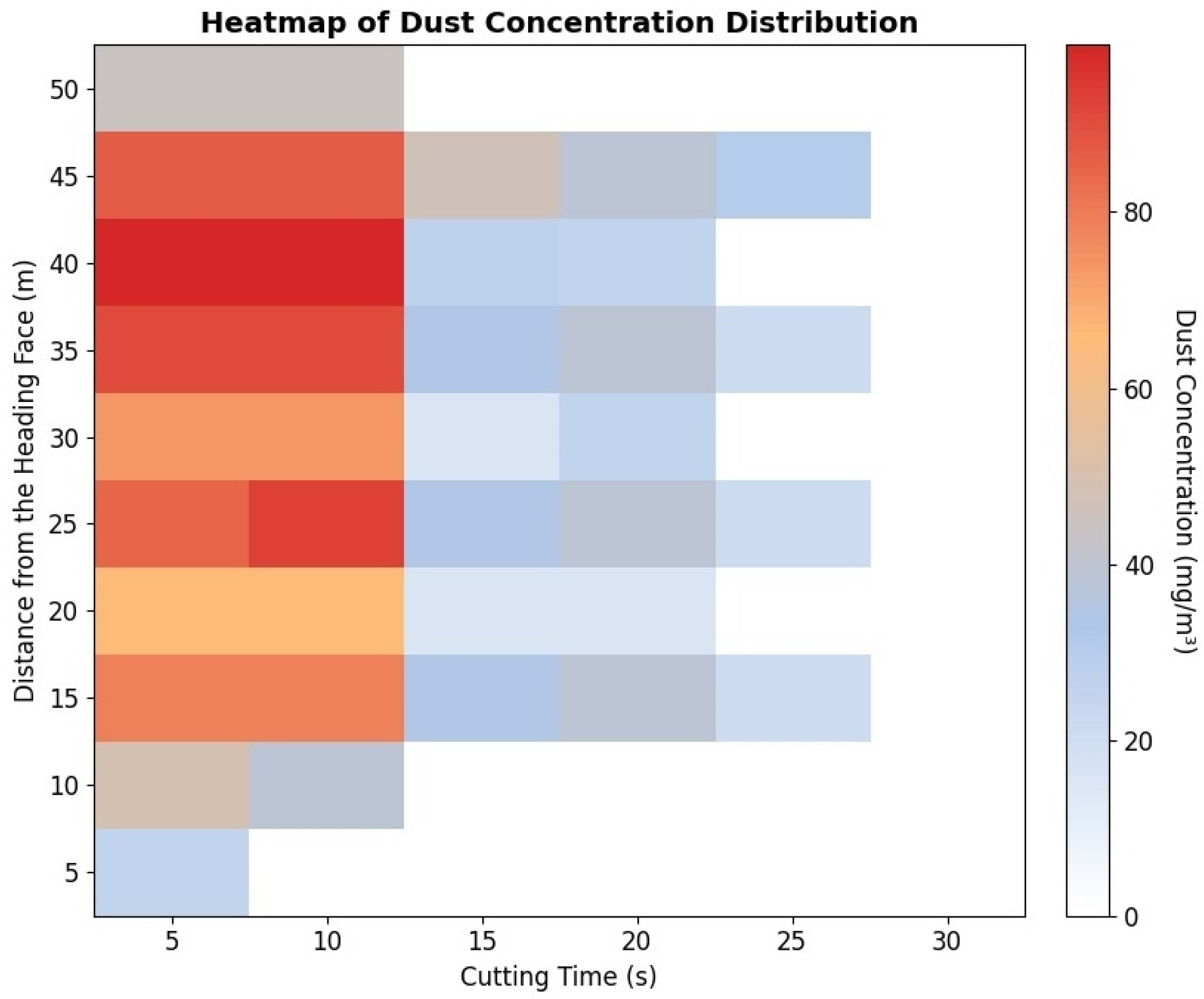
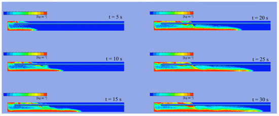
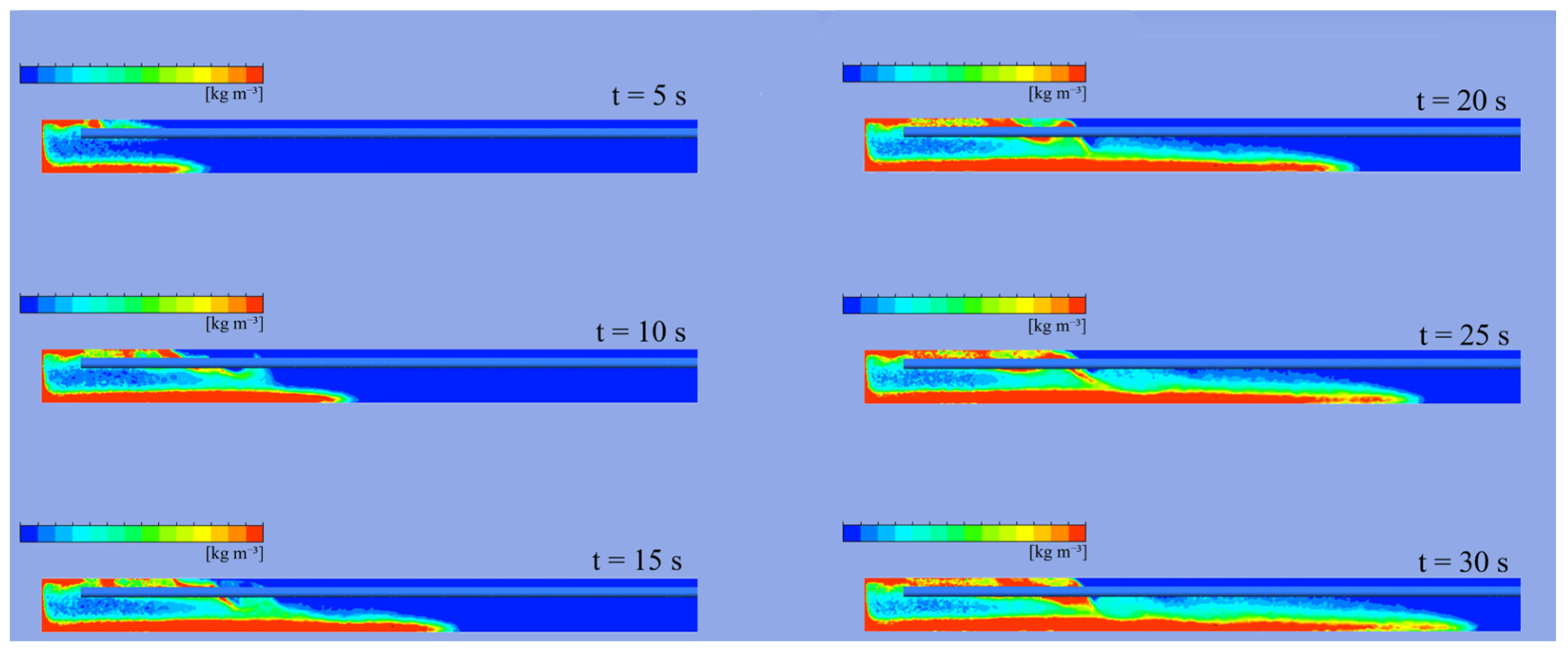
Figure 8 shows the diffusion of dust with different concentrations in the roadway at different durations of cutting. Under long-forcing and short-exhausting ventilation conditions, the dust distribution pattern in the heading face exhibits significant three-zone characteristics, and the zoning basis is determined according to the dust concentration level, airflow field characteristics and dust migration rate: (1) High-concentration accumulation zone (0–15 m from the heading face): This zone is the dust source area, with complex flow field and numerous vortices, the average dust concentration is higher than 30 mg/m3, accounting for more than 85% of the total dust in the roadway, and the dust migration rate is slow. (2) Medium-concentration transition zone (15–35 m from the heading face): The airflow field in this zone gradually stabilizes, the average dust concentration is between 5 and 30 mg/m3, and the dust diffuses to the rear roadway under the drive of airflow. (3) Low-concentration settling zone (beyond 35 m from the heading face): The airflow in this zone is uniform, the average dust concentration is lower than 5 mg/m3, and the dust mainly settles under the action of gravity. The diffusion rate of dust increases gradually across the three zones. It should be noted that this three-zone distribution characteristic is applicable to the large-section (20 m2) long-distance heading face with long-forcing and short-exhausting ventilation in this study, and the zoning boundary may shift slightly for roadways with different cross-sectional sizes and ventilation parameters. This is primarily due to the complex airflow at the heading face, where recirculating air causes substantial dust to circulate in the front part of the heading roadway. In contrast, the simple spatial structure and uniform airflow distribution in the rear part of the roadway facilitate more efficient dust migration by the airflow.
Figure 8.
Heatmap of dust concentration distribution.
As shown in Figure 9, under the long-forcing and short-exhausting ventilation setup, the initial dust concentration near the heading face is exceptionally high. As the continuous cutting time increases, this high-concentration dust cloud diffuses to the rear of the roadway, gradually being diluted by the forcing fresh airflow until the overall spatial dust distribution reaches a steady dynamic equilibrium.
Figure 9.
Dust concentration distribution at breathing zone height Y = 1.2 m in the heading roadway.
Figure 10 shows that a large amount of dust is continuously produced at the heading face once the roadheader operates. Driven by the high-speed jet from the forcing duct, the dust quickly mixes with the turbulent airflow, rebounds after hitting the right tunnel wall, and diffuses backward in a concentrated flow. Affected by the obstruction of the roadheader, an obvious recirculation vortex forms in its wake, leading to dust trapping and accumulation. Under gravity, coarse particles gradually settle on the floor, while fine respirable dust disperses and diffuses further into the tunnel.
Figure 10.
Dust concentration distribution at the return air side Z = 0.35 m in the heading roadway.
Respirable dust with particle size less than 5 μm is the main cause of coal workers’ pneumoconiosis, and its concentration distribution is the core index to evaluate the occupational health risk of the working environment. Based on the post-processing of FLUENT simulation results, the concentration distribution of respirable dust in the roadway is extracted and analyzed.
The results show that the migration law of respirable dust is generally consistent with the total dust, but its suspension time is longer, and it is more likely to diffuse to the rear roadway with the airflow. Under the baseline scheme (Scheme 1), the respirable dust accounts for 42.7% of the total dust in the breathing zone (Y = 1.2 m), and its concentration in the 0–15 m high-concentration zone is as high as 18.6 mg/m3. After parameter optimization, the respirable dust concentration in the breathing zone is reduced by up to 58.9%, and 82% of the respirable dust is restricted within 0–15 m from the heading face, which significantly reduces the occupational health risk. The distribution of respirable dust is more sensitive to the forcing-to-exhausting air volume ratio and the installation height of the ducts: when K < 1, the respirable dust is easy to diffuse to the rear roadway with the vortex; when the duct installation height is lower than 0.5 times the roadway height, the respirable dust concentration in the breathing zone increases significantly.
4. Ventilation Effects on Dust Migration Characteristics
To optimize the dust removal efficiency of the long-forcing and short-exhausting ventilation system, it is essential to thoroughly investigate the impact of critical spatial parameters on dust dispersion. As clarified in Section 3, the dust migration in the heading face presents significant zonal distribution characteristics, which are essentially dominated by the spatial structure of the airflow field, while the installation layout of forcing and exhausting ducts is the core factor determining the airflow field distribution. Unlike the air volume ratio that dominates the overall pressure balance of the ventilation system, the spatial layout parameters of ducts directly regulate the local airflow structure, vortex development range and dust capture path, and can be flexibly adjusted in field engineering with low modification cost. Therefore, this section systematically analyzes the influence of various ventilation configurations—specifically the lateral installation position, axial distance from the heading face, and vertical installation height of the exhausting and forcing ducts—on the dynamic migration characteristics and spatial concentration distribution of dust within the heading roadway, using the single-factor variable control method consistent with the simulation scheme design in Section 2.4.
4.1. Influence of the Distance Between Exhausting Duct and Return-Air Side Wall on Dust Migration in the Roadway
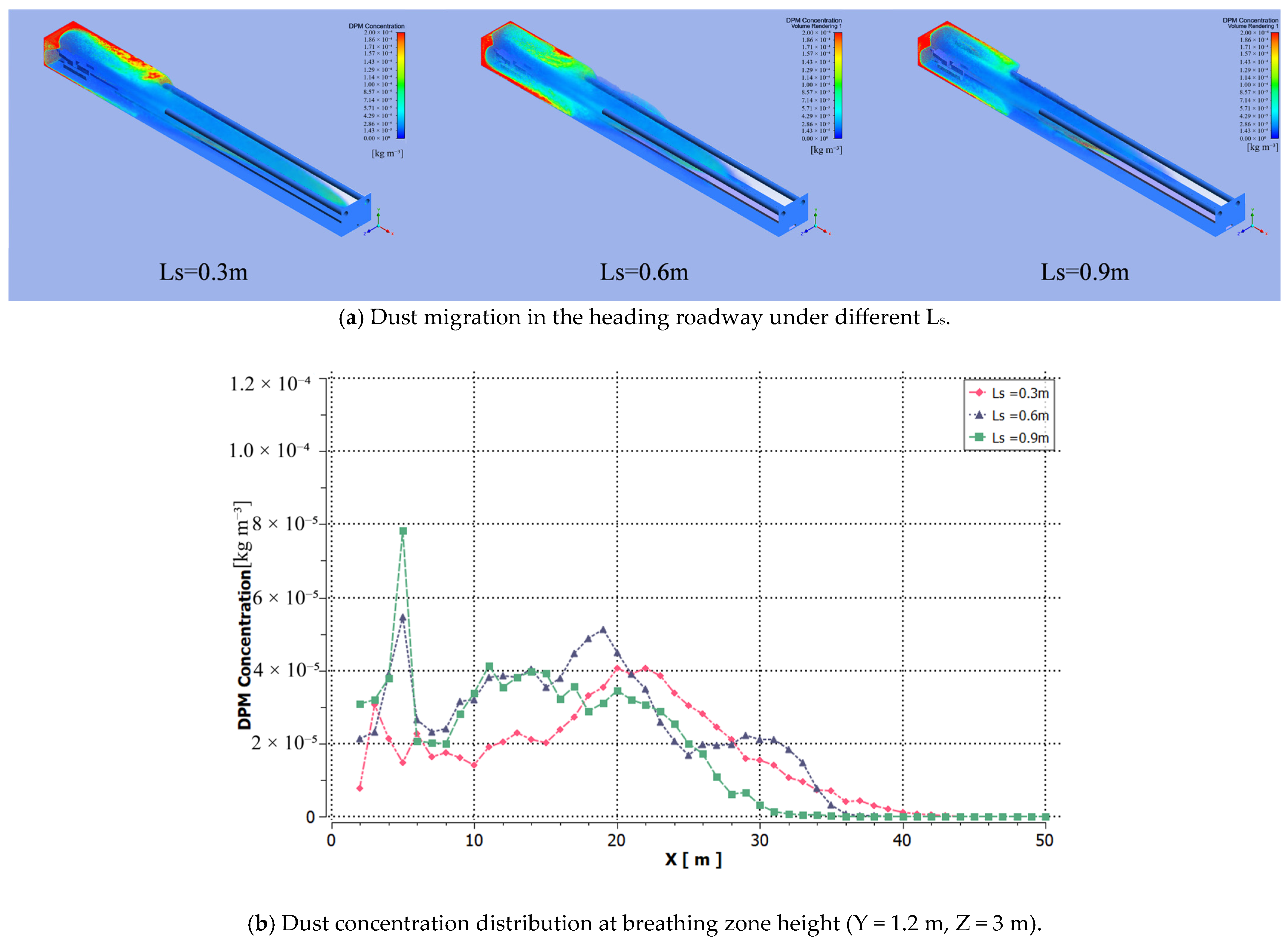
The lateral installation position of the exhausting duct is a key spatial parameter that is easily overlooked in empirical engineering design, but it can significantly alter the localized airflow field structure, negative pressure coverage range of the exhausting inlet, and its subsequent dust capture capabilities. In the large-section heading roadway of this study, the boundary effect of the roadway side wall has a non-negligible impact on the development of ventilation jet and recirculation vortex; the lateral offset of the exhausting duct will directly change the airflow migration path on the return air side, and then affect the accumulation and diffusion of high-concentration dust generated by the heading face. To quantitatively evaluate this effect and clarify the optimal lateral installation position of the exhausting duct, numerical simulations were meticulously conducted under varying distances Ls between the exhausting duct and the return-air side wall, with other ventilation parameters (Lc, Ly, H, K) strictly fixed at the values of the baseline scheme (Scheme 1) to ensure the independence of the single-factor analysis. The resulting dust migration characteristics and corresponding concentration distributions under different Ls conditions are intuitively presented in Figure 11.
Figure 11.
Dust migration and concentration at exhausting duct distances from the return air wall.
First, the influence of the distance Ls between the exhausting duct and the coal wall on dust migration in the roadway was analyzed using Schemes 1, 2 and 3 in Table 3. Simulation results in Figure 11a show that when Ls = 0.3 m, dust mainly concentrates in the upper corner, roof and return airflow of the heading face, with relatively smooth migration. When Ls increases to 0.6 m and 0.9 m, dust accumulation on the inlet air side wall rises significantly. Figure 11b further illustrates that dust control near the heading face becomes poorer at larger Ls. This occurs because moving the exhausting duct toward the roadway center intensifies local airflow recirculation. Dust must travel a longer path—return air side → upper roadheader → return air side—before being captured, which slows diffusion and causes severe accumulation around the roadheader with sustained high dust concentrations.
Therefore, within the set parameter range (Ls = 0.3–0.9 m) of this study, positioning the exhausting duct closer to the return air side with Ls = 0.3 m achieves the best dust control performance. When Ls is less than 0.3 m, the duct will be too close to the sidewall, which will increase the airflow resistance and reduce the effective suction range of the exhausting inlet, thus reducing the dust capture efficiency. Ls = 0.3 m is the optimal value within the set parameter range of this study.
4.2. Influence of the Distance Between Exhausting Inlet and Heading Face on Dust Migration in the Roadway
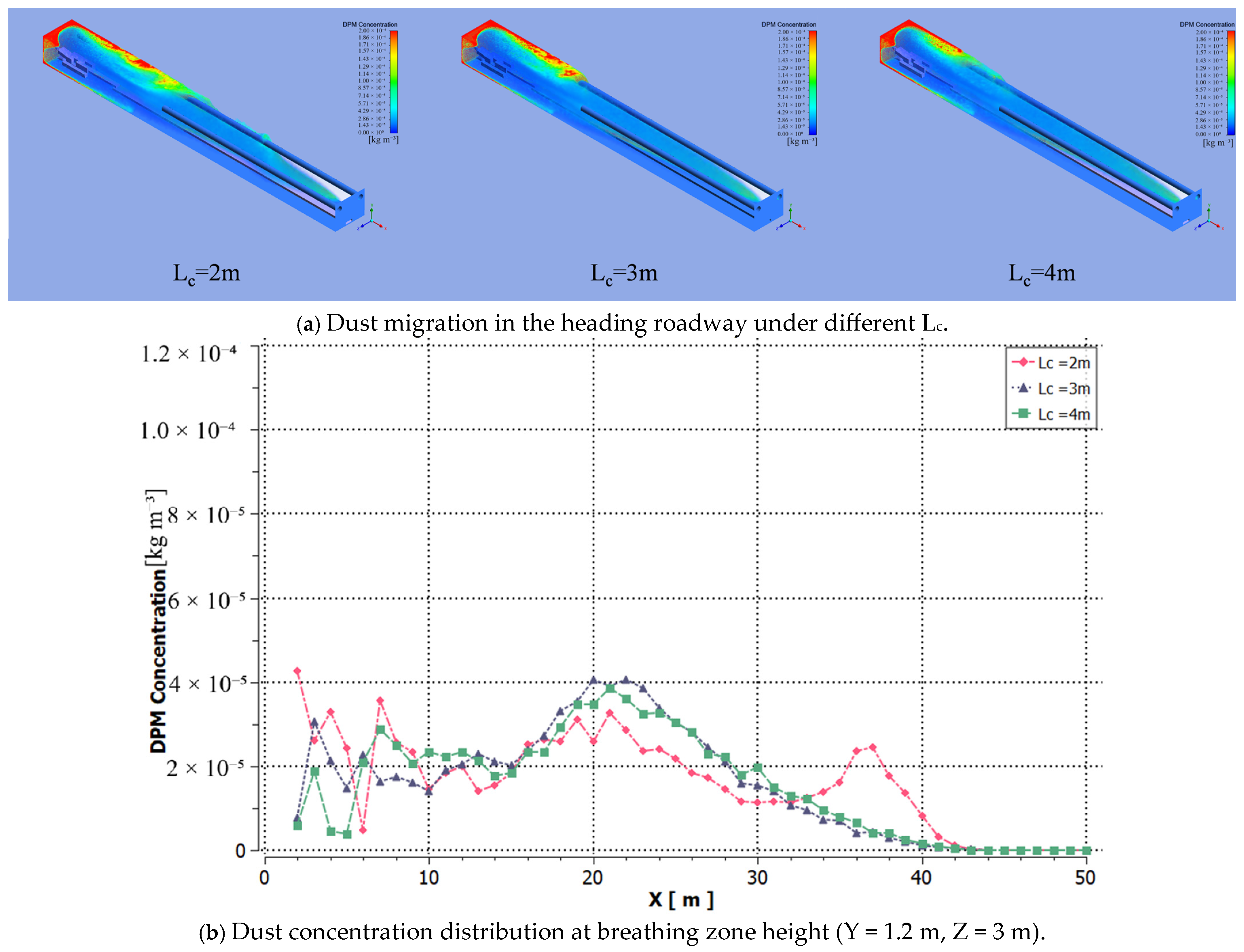
Alongside the lateral installation position, the longitudinal distance Lc between the exhausting inlet and the heading face is a critical parameter that determines the effective capture range of the ventilation system. To systematically analyze its impact on dust dispersion and removal efficiency, numerical simulations were conducted under varying Lc conditions. The resulting dust migration characteristics and spatial concentration distributions are presented in Figure 12.
Figure 12.
Dust migration and concentration at exhausting inlet distances from the heading face.
To analyze the influence of the distance Lc between the exhausting inlet and the heading face on dust migration in the roadway, the distance Ls = 0.3 m between the exhausting duct and the return-air side wall was kept constant. Data from Schemes 1, 4, and 5 in Table 3 were introduced into the model. As shown in Figure 12a, when Lc = 2 m and 3 m, the dust concentration in the return air side and at the working face is higher than that at Lc = 4 m. Specifically, the dust migration rate and diffusion at Lc = 4 m are significantly better than those at Lc = 2 m and 3 m. Figure 12b shows that when Lc = 2 m, the dust concentration distribution at breathing zone height fluctuates significantly. When Lc = 3 m and 4 m, the dust concentration distributions are similar, but the dust concentration near the working face at Lc = 4 m is notably lower, indicating that the exhausting duct functions more effectively. This is because moving the exhausting inlet away from the working face expands the negative forcing zone, improving dust capture efficiency. The farther the exhausting inlet is from the working face, the more uniform the nearby airflow field distribution becomes, enabling better inhalation of dust from the working face into the exhausting duct.
The simulation results within the range of 2–4 m show that the dust control effect is the best when Lc = 4 m. It should be noted that only three levels of Lc (2 m, 3 m, 4 m) are set in this study within the common engineering range. When Lc > 4 m, the negative pressure capture range of the exhausting inlet will continue to expand, but the suction force per unit area will decrease, which may lead to the reduction in dust capture efficiency. Therefore, Lc = 4 m is the optimal value within the set parameter range of this study, and the optimal Lc for other working conditions needs to be further verified according to the actual roadway conditions. For the 20 m2 cross-section roadway in this study, setting Lc = 0.9√A (≈4 m) can achieve a good dust control effect.
4.3. Influence of the Distance Between Forcing Inlet and Heading Face on Dust Migration in the Roadway
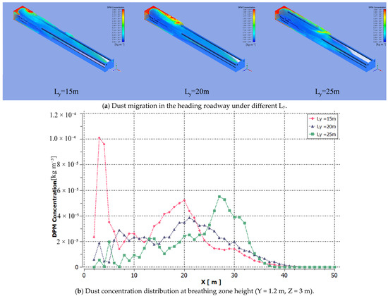
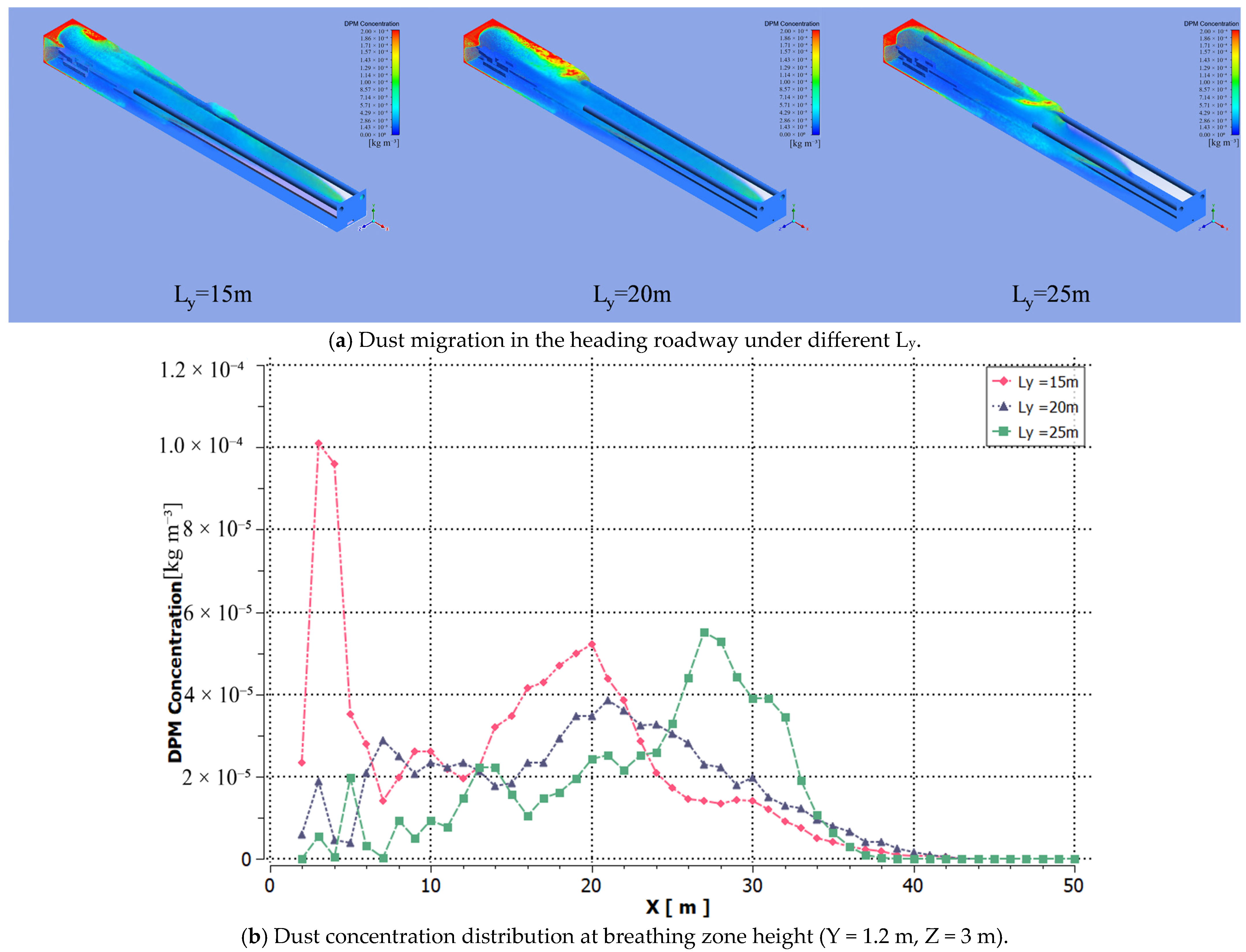
To analyze the influence of the distance Ly between the forcing inlet and the heading face on dust migration in the roadway, the distances Ls = 0.3 m (between the exhausting duct and the return-air side wall) and Lc = 4 m (between the exhausting inlet and the heading face) were kept constant. Data from Schemes 1, 6, and 7 in Table 3 were introduced into the model. As shown in Figure 13a, when Ly = 15 m, dust at the heading face accumulates at the exhausting inlet, with an increased lateral diffusion range of dust. This is because the excessively short distance from the forcing inlet to the heading face creates a vortex zone between the roadheader and the working face, causing dust to circulate within the vortex zone without being extracted from the roadway. Figure 13b shows significant differences in dust concentration distribution in the roadway under different Ly. At Ly = 20 m and 25 m, the dust concentration at the heading face decreases significantly, and the lateral diffusion range of dust is controlled. However, at Ly = 25 m, the dust diffusion rate is slower, leading to high-concentration dust in the 26–32 m range from the working face, resulting in a worse dust control effect than at Ly = 20 m.
Figure 13.
Dust migration and concentration distribution at different inlet–heading face distances.
Therefore, within the set parameter range (Ly = 15–25 m) of this study, setting Ly to 20 m (Ly = 4.5√A m, for the 20 m2 cross-section roadway in this study) achieves the best dust control effect. When Ly exceeds 25 m, the jet from the forcing inlet will decay excessively before reaching the heading face, resulting in insufficient airflow velocity at the heading face, which cannot effectively drive dust migration to the exhausting inlet, and may lead to dust accumulation in front of the roadway. When Ly is less than 15 m, the jet will form a strong vortex zone between the roadheader and the heading face, causing dust to circulate and cannot be effectively extracted. Ly = 20 m is the optimal value within the set parameter range of this study.
4.4. Influence of Duct Installation Height on Dust Migration in the Roadway
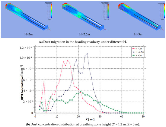
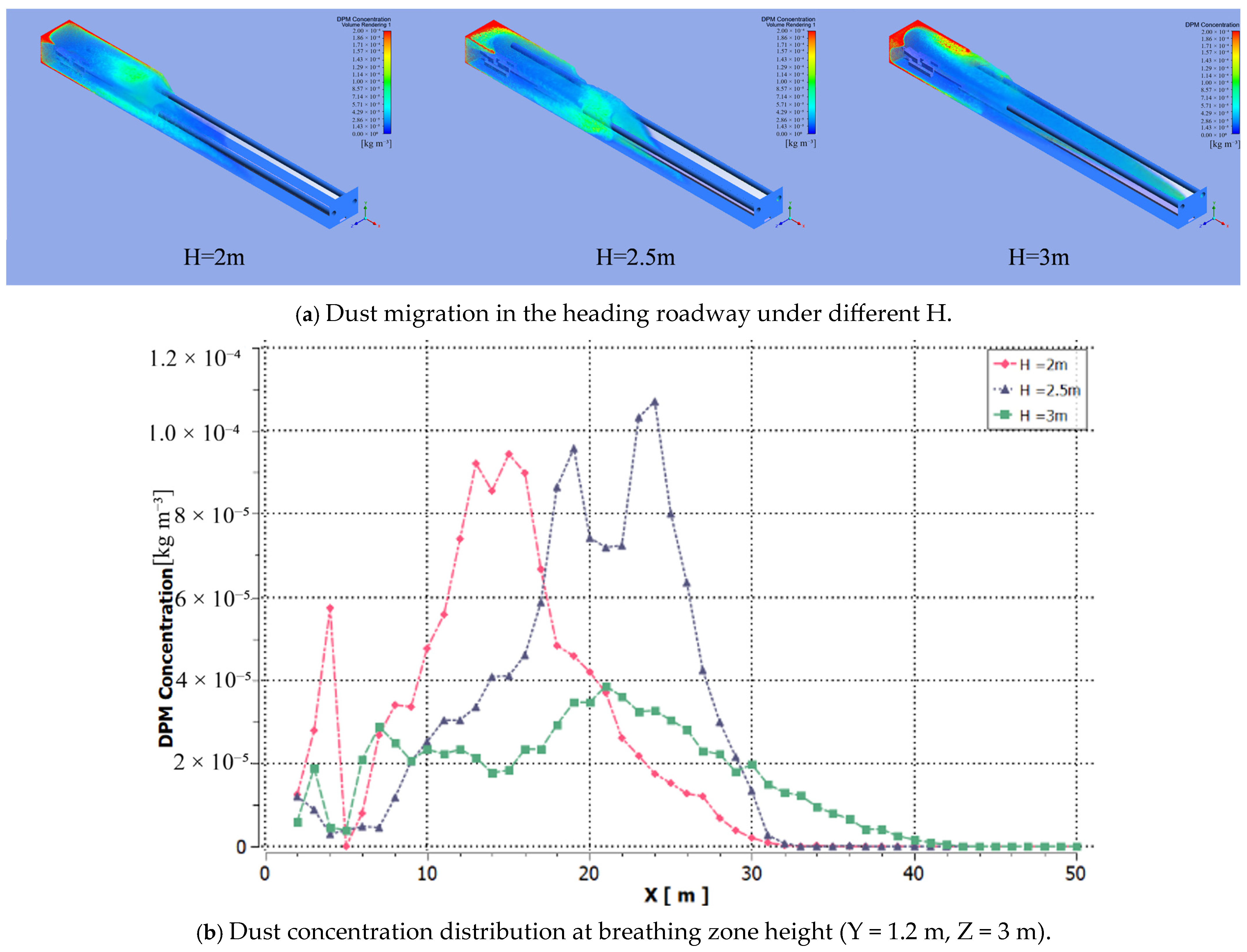
To analyze the influence of the installation height H of the two ducts on dust migration in the roadway, the distances Ls = 0.3 m (between the exhausting duct and the return-air side wall), Lc = 4 m (between the exhausting inlet and the heading face), and Ly = 20 m (between the forcing inlet and the heading face) were kept constant. Data from Schemes 1, 8, and 9 in Table 3 were introduced into the model. As shown in Figure 14a, the greater the duct height H, the stronger the suction effect of the exhausting duct on dust, causing more dust to concentrate at the exhausting inlet and reducing the migration distance along the return air side. Figure 14b shows that when the duct installation height H = 2 m and 2.5 m, the dust control effect in the roadway is less ideal compared to H = 3 m, with slow dust diffusion and an excessively large lateral diffusion range in the entire tunnel. When the duct installation height is low, the airflow migration space is restricted, leading to reduced airflow velocity and an expanded vortex zone between the roadheader and the working face, between the two ducts, and behind the roadheader. This causes dust to accumulate in the vortex zone without effective diffusion.
Figure 14.
Dust migration and concentration distribution under different duct installation heights.
Therefore, within the set parameter range (H = 2–3 m) of this study, setting H = 3 m (approximately 0.75 times the roadway height) achieves the best dust control effect. When H exceeds 0.75 times the roadway height, the duct will be too close to the roof, and the suction effect of the exhausting inlet on the dust in the breathing zone (1.2 m height) will be significantly weakened, leading to an increase in dust concentration in the operating area. When H is lower than 0.75 times the roadway height, the airflow migration space is restricted, and the vortex zone in the roadway will expand, causing dust accumulation. H = 3 m is the optimal value within the set parameter range of this study.
4.5. Influence of Forcing–Exhausting Air Volume Ratio on Dust Migration in the Roadway
The forcing–exhausting air volume ratio K is a core characteristic parameter for hybrid forcing–exhausting ventilation systems, which directly determines the overall airflow field structure and dust control performance in the heading face. The airflow field distribution and dust migration law in the heading roadway will show significant differences under different K values, making it a key variable for ventilation parameter optimization of long-forcing and short-exhausting systems.
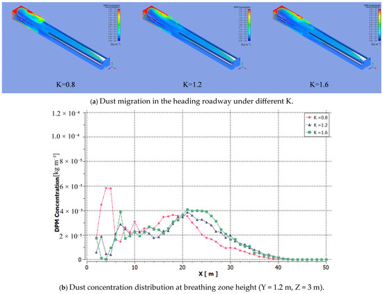
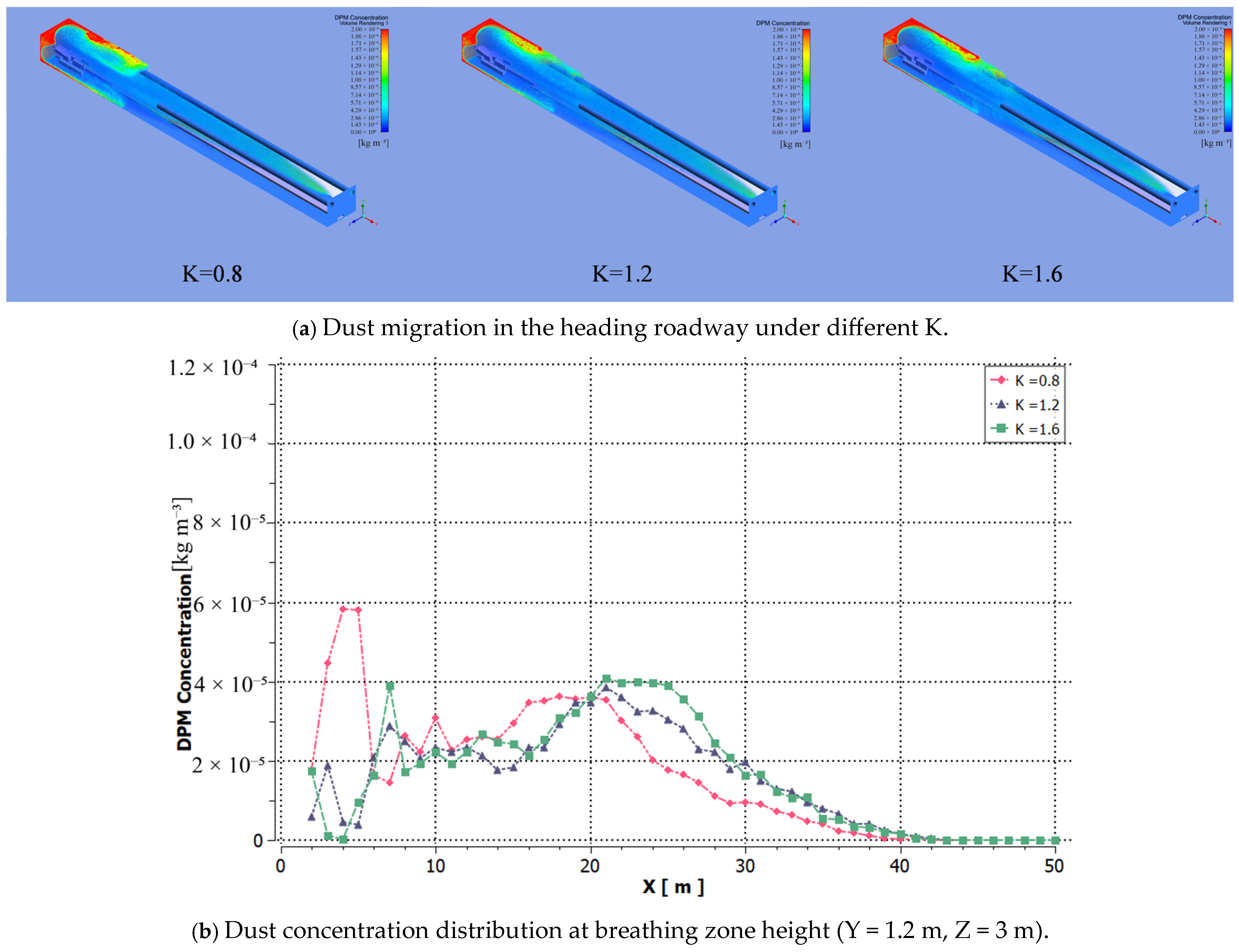
The previous four groups of simulation cases all fixed K at 1.2 (a common empirical value in coal mine engineering) to analyze the independent influence of different duct spatial layout parameters on dust migration, eliminating the coupling interference of air volume matching and ensuring the rigor of single-factor analysis. In this section, the same single-factor variable control method is adopted: the forcing air volume is kept constant at 300 m3/min (the inlet air velocity of the forcing duct is fixed at 10 m/s), which meets the minimum fresh air demand of the heading face specified in the Coal Mine Safety Regulations. On this basis, the forcing-to-exhausting air volume ratio K is adjusted only by changing the exhausting air volume, with three typical working conditions set: 250 m3/min exhausting air volume for K = 1.2, 375 m3/min for K = 0.8, and 187.5 m3/min for K = 1.6.
It should be noted that, due to the fixed diameter of the exhausting duct (0.8 m), the change in exhausting air volume will inevitably lead to the corresponding linear change in the air velocity at the exhausting inlet, which is −8 m/s for K = 1.2, −10 m/s for K = 0.8 and −6 m/s for K = 1.6 (the negative sign represents the airflow direction towards the exhausting duct). Therefore, the change in dust migration law under different K values is the comprehensive result of the combined effect of air volume ratio and exhausting inlet air velocity. Among them, the air volume ratio determines the overall pressure distribution and large-scale airflow pattern in the roadway, which is the dominant factor affecting the overall dust migration characteristics; the exhausting inlet air velocity only affects the local dust capture efficiency near the inlet, which is the secondary influencing factor.
To analyze the influence of K on dust migration in the roadway, the distances Ls = 0.3 m, Lc = 4 m, Ly = 20 m, and duct installation height H = 3 m were kept constant. Data from Schemes 1, 10, and 11 in Table 3 were introduced into the model. As shown in Figure 15a, dust migration at the heading face changes with K. When K = 0.8 (smaller forcing–exhausting ratio), the excessive air velocity at the exhausting inlet causes most dust to accumulate on the exhausting side, with some dust returning to the working face with the airflow, leading to an expanded lateral diffusion range and higher dust concentration. When K = 1.2 and 1.6, the air velocity at the forcing inlet is greater than that at the exhausting duct, making the forcing inlet dominant. Part of the dust is discharged from the roadway outlet, and part is extracted by the exhausting duct, with dust mainly concentrating on the return air side. Under the suction effect of the exhausting duct, dust is stably extracted. Figure 15b shows that the dust concentration in the vortex zone at the front of the roadway is significantly higher when K = 0.8 compared to K = 1.2 and 1.6. Through comprehensive analysis of the simulation results within the range of K = 0.8–1.6, it is concluded that in long-forcing and short-exhausting ventilation, the forcing air volume should be set to be greater than the exhausting air volume (i.e., K > 1), and controlling K within the range of 1.2–1.6 can achieve a good dust control effect in this study. It should be noted that only three levels of K (0.8, 1.2, 1.6) are set in this study. When K > 1.6, the excessive forcing air volume will intensify the vortex formation near the heading face, which may lead to secondary dust resuspension and the diffusion of high-concentration dust to the rear roadway, thus reducing the dust control efficiency. Therefore, the recommended range of K = 1.2–1.6 is the optimal range within the set parameter range of this study, and the optimal K value for other working conditions needs to be further verified according to the actual on-site conditions.
Figure 15.
Dust behavior and distribution under forcing–exhausting volume ratios.
Table 4 summarizes the dust control effects of all 11 simulation schemes. Compared with the baseline case, most parameter adjustments reduce dust suppression efficiency to varying extents. The results show that parameter changes have a significant impact on dust concentration in the breathing zone and the range of high-concentration dust regions, with some schemes even leading to a notable deterioration of the working environment.
Table 4.
Summary of dust control effects of 11 simulation schemes.
5. Discussion
5.1. Comparison with Previous Studies
To highlight the academic contribution of this study, it is essential to compare the currently optimized parameters with existing literature. Consistent with the findings of Zhou et al. [9] and Wen et al. [11], our results confirm that a forcing–exhausting air volume ratio (K) greater than 1 is strictly necessary to suppress dust resuspension effectively. However, while previous studies primarily provided qualitative trends or broad empirical ranges, this study precisely narrows down the optimal ratio to K = 1.2–1.6 by specifically targeting the aerodynamic vortex behaviors in the 2-2 Upper Coal Working Face.
Furthermore, regarding duct layout, Hua et al. [8] and Nie et al. [10] emphasized the impact of spatial distance, yet their studies often relied on simplified or idealized roadway models. In contrast, by incorporating full-scale physical obstructions, such as the roadheader and belt conveyor, into the CFD-DPM, our study quantitatively determined that setting the duct installation height at approximately 0.75 times the roadway height (H = 3 m) maximizes dust capture efficiency without exacerbating wake vortices. Overall, compared to the general airflow–dust coupling models established by Yu et al. [7], the refined parameter set in this paper (e.g., Lc ≈ 0.9√A, Ly ≈ 4.5√A for the 20 m2 cross-section roadway in this study) provides a quantitative reference for the parameter design of long-forcing and short-exhausting ventilation in similar large-section headings, and bridges the gap between theoretical two-phase flow simulations and practical engineering guidance.
5.2. Optimized Engineering Scheme for Ventilation Parameters
Based on the numerical simulation results in Chapter 3, the optimized parameters for the long-forcing and short-exhausting ventilation system (Ls = 0.3 m, Lc = 0.9√A, Ly = 4.5√A, H = 0.75 times roadway height) and a forcing–exhausting ratio (K = 1.2–1.6) provide critical references for practical engineering in mining areas. However, transitioning from simulation to field implementation requires further design and validation considering specific site conditions. Therefore, based on the simulation results, practical engineering schemes are proposed from three aspects: duct layout design, equipment selection and air volume matching, and breathing zone protection with zoned dust control.
- Duct Layout Engineering Design
The distance between the exhausting duct and the return-air side wall (Ls = 0.3 m) is key to suppressing dust accumulation on the roadway sidewall (Figure 11). During roadway construction, laser positioning devices are recommended to ensure the exhausting duct is close to the return air side, minimizing frictional resistance between the airflow and the wall. The distance between the exhausting inlet and the heading face Lc = 0.9√A (for the 20 m2 cross-section roadway in this study, where A is the roadway cross-sectional area, A = 20 m2, yielding Lc ≈ 4.0 m) and the distance between the forcing inlet and the heading face Ly = 4.5√A (Ly = 20 m in this study) are the fitting results of this study, which should be dynamically adjusted according to the actual roadway cross-section, and are not universal formulas. For large-section roadways (A > 25 m2), modular supports can be used to fix duct positions through formula-based calculations, avoiding dust control blind spots caused by empirical values.
- 2.
- Equipment Selection and Air Volume Matching
A forcing–exhausting ratio K = 1.2–1.6 requires the forcing fan air volume to be slightly larger than the exhausting fan air volume (300 m3/min for forcing and 250 m3/min for exhausting in this study). In engineering practice, variable-frequency speed-regulating fans are recommended. A PLC control system should be used to adjust air volumes in real time, ensuring the optimal forcing–exhausting ratio is maintained as the roadway extends. Fan models must balance roadway air velocity requirements (≥0.25 m/s) and dust capture efficiency to prevent high-concentration dust retention due to insufficient air volume (Figure 15).
- 3.
- Breathing Zone Protection and Zoned Dust Control
Simulations show that dust concentration at breathing zone height (Y = 1.2 m) is significantly influenced by ventilation parameters (Figure 9 and Figure 10). Engineering designs must prioritize airflow stability in this area by installing both ducts at 0.75 times the roadway height. For roadways of different heights, the installation height should be adjusted proportionally (H = 0.75 times roadway height) to avoid expanding vortex zones caused by low duct positions (Figure 14). A 0–15 m high-concentration zone (Figure 8): In addition to optimizing ventilation parameters, air curtain barriers, such as high-forcing spray air curtains and roadheader-mounted dust collectors should be added to form a multi-level dust control system of “ventilation guidance-air curtain isolation-equipment exhausting.” A 15–35 m medium-concentration zone: Automatic spray dust suppression devices with dust wetting agents can be deployed to enhance dust settlement. A >35 m low-concentration zone: Regular roadway flushing should be implemented to reduce secondary dust resuspension.
These measures integrate simulation-based parameter optimization with engineering practice, aiming to create a systematic and adaptive dust control strategy for a heading face under long-forcing and short-exhausting ventilation.
According to the Coal Mine Safety Regulations and Occupational Exposure Limits for Hazardous Factors in the Workplace, the maximum allowable concentration of total dust in the underground coal mine working face is 4 mg/m3, and the maximum allowable concentration of respirable dust is 2.5 mg/m3. The optimized ventilation scheme can reduce the average total dust concentration in the breathing zone to 12.6 mg/m3, and the respirable dust concentration to 5.4 mg/m3. It should be noted that the simulation in this study only considers the dust control effect of ventilation, and the dust concentration can be further reduced to meet the standard limit by combining with spray dust suppression, dust collector and other auxiliary dust control measures, which is also the core of the multi-level dust control system proposed in this study.
5.3. Future Perspectives and Engineering Applications
This study has several non-negligible limitations, which are explicitly stated as follows: (1) All conclusions in this paper are derived from numerical simulation results, and have not been verified by field industrial tests or laboratory physical model tests; the deviation between the simulated airflow–dust coupling behavior and actual underground working conditions needs further on-site monitoring and validation. (2) The model neglects particle–particle collision and agglomeration effects in the 0–15 m high-concentration dust zone, which may lead to a slight overestimation of suspended dust concentration in the simulation results; meanwhile, the migration and settlement process of dust particles inside the exhausting duct after capture is not considered, which reduces the realism of the model to a certain extent. (3) This study adopts a single-factor analysis method, which only clarifies the independent influence of each ventilation parameter on dust migration, without considering the interaction and coupling effect between multiple parameters. (4) The simulation is established based on static geometric conditions, without considering the dynamic disturbance of roadway excavation advancement and equipment movement on the airflow field structure during actual heading operations.
To address the above limitations and further improve the engineering applicability of the research results, future research will focus on the following aspects: (1) Priority will be given to field industrial trials in the target mine to verify the long-term reliability of the optimized ventilation parameters, and the numerical model will be corrected and optimized based on the deviation between on-site measured data and simulation results. (2) Orthogonal test or response surface methodology will be adopted to systematically analyze the interaction between multiple ventilation parameters, and a universal multi-parameter collaborative optimization model suitable for different roadway cross-sections will be established. (3) An adaptive dynamic parameter adjustment system will be developed by integrating real-time dust concentration and air velocity sensing data with variable-frequency fan control, to realize dynamic matching between ventilation parameters and heading advancement speed. (4) A dust-gas coupled control model will be established to coordinate the dual goals of dust control and gas hazard prevention, so as to further improve the intrinsic safety of underground heading operations.
6. Conclusions
This study takes the 2-2 upper coal working face in the Xintai Taigemiao Mining Area as the research object. Using ANSYS Fluent 2021 R2 numerical simulation software, the airflow distribution and dust migration characteristics under long-forcing and short-exhausting ventilation conditions are determined. The dust control effects and influence characteristics of five ventilation parameters are studied: the distance between the exhausting duct and the return-air side wall, the distance between the exhausting inlet and the heading face, the distance between the forcing inlet and the heading face, the installation height of the two ducts, and the forcing–exhausting air volume ratio. Based on this, the ventilation parameters for the long-forcing short-exhausting system are optimized. The results are as follows:
- Dust Migration Characteristics and Concentration Zoning in the Heading Roadway
Within the scope of this numerical simulation, within the 0–15 m range from the heading face, the airflow field contains numerous vortices, with significant variations in the air velocity contour. Dust accumulates heavily in this area, with slow migration speed and high concentration. As the distance from the heading face increases, the streamlines gradually smooth out, and dust is continuously transported toward the roadway outlet under the action of airflow. Both the air velocity and dust concentration distributions gradually stabilize. Ultimately, the dust concentration distribution in the heading roadway exhibits three-zone characteristics: a 0–15 m high-concentration dust zone, a 15–35 m medium-concentration dust zone, and a 35–50 m low-concentration dust zone.
- 2.
- Optimization of Ventilation Parameters and Dust Control Mechanism
Within the scope of this numerical simulation, through numerical simulation of the overall dust migration process in the heading roadway under different ventilation conditions, the optimal installation positions for the forcing and exhausting ducts within the set parameter range for the 20 m2 cross-section roadway in this study are determined as follows: The exhausting duct should be as close as possible to the return air side of the heading roadway, with a distance of Ls = 0.3 m from the coal wall. The distance between the exhausting inlet and the heading face is Lc = 4 m (0.9√A, where A is the roadway cross-sectional area). The distance between the forcing inlet and the heading face is Ly = 20 m (4.5√A). The duct installation height H = 3 m, which is 0.75 times the roadway height (4 m in this study). The above coefficient values (0.9√A, 4.5√A) are derived from the simulation results of the 20 m2 cross-section roadway in this study, which can provide a preliminary reference for the parameter design of similar roadways. The specific values must be verified and adjusted according to the actual roadway cross-sectional size, geological conditions and on-site construction environment.
In practical applications, the forcing air volume should be set to be greater than the exhausting air volume, with the forcing duct playing a dominant role. The recommended forcing–exhausting air volume ratio K is 1.2–1.6 within the parameter range of this study. By setting the ventilation parameters according to the above scheme, compared with the non-optimized scheme, the average total dust concentration in the breathing zone is reduced by up to 62.3%, the respirable dust concentration is reduced by up to 58.9%, and 85% of the high-concentration dust is restricted within 0–15 m from the heading face, which can efficiently control dust dispersion and significantly improve the working environment in the breathing zone.
- 3.
- Engineering Application Reference
Within the scope of this numerical simulation, the optimized parameter scheme provides a quantifiable design reference for dust control in similar heading faces. The optimized configuration can effectively suppress dust accumulation in the 0–15 m high-concentration zone, shorten the dust diffusion path in the 15–35 m transition zone, and accelerate dust settlement in the zone beyond 35 m. Combined with variable-frequency fan dynamic adjustment, roadheader-mounted dust collectors, and spray dust suppression, a multi-level dust control system can be formed to further reduce the occupational health risk for underground workers.
In the future, further research should focus on developing a parameter adaptive adjustment system combined with intelligent sensing technology to promote the collaborative intelligence of ventilation dust control and heading equipment, providing precise solutions for dust prevention and control in high-yield and high-efficiency mines.
Author Contributions
Conceptualization, Y.L. and W.X.; methodology, W.X. and C.L.; software, Y.Z. and Z.S.; resources, C.L.; data curation, Y.Z.; writing—original draft preparation, Y.Z.; writing—review and editing, C.X.; visualization, Z.S.; supervision, Y.C.; project administration, Y.L. and C.X.; funding acquisition, Y.L. and Y.C. All authors have read and agreed to the published version of the manuscript.
Funding
This research was funded by the Key Research Program of China Coal Science and Industry Group, grant number 2024-TD-ZD011-02; the Scientific Research Project of Chinese Institute of Coal Science, grant number 2025-MKZY-ZL-001; and the National Natural Science Foundation of China, grant number 52204220.
Data Availability Statement
The data that support the findings of this study are available from the corresponding author upon reasonable request.
Conflicts of Interest
Author Yingjie Liu, Wenhao Xian, Yongbo Cai, Zuo Sun, Chi Li were employed by Tiandi Science and Technology Co., Ltd. The remaining authors declare that the research was conducted in the absence of any commercial or financial relationships that could be construed as a potential conflict of interest.
References
- National Bureau of Statistics of China. Energy Production in December 2024. Available online: http://www.stats.gov.cn/ (accessed on 17 January 2025).
- Hoy, R.F.; Jeebhay, M.F.; Cavalin, C.; Chen, W.; Cohen, R.A.; Fireman, E.; Go, L.H.T.; León-Jiménez, A.; Menéndez-Navarro, A.; Ribeiro, M.; et al. Current global perspectives on silicosis—Convergence of old and newly emergent hazards. Respirology 2022, 27, 387–398. [Google Scholar] [CrossRef] [Scilit] [PubMed]
- Qin, B.T.; Zhou, G.; Zhou, Q.; Wang, H.T.; Peng, H.T.; Wei, X.Y. Technology system and application of activated magnetized water spray dust reduction in fully mechanized coal mining face. J. China Coal Soc. 2021, 46, 3891–3901. (In Chinese) [Google Scholar]
- Lu, X.X.; Wang, C.Y.; Xing, Y.; Shen, C.; Shi, G. Investigation on the dust migration behavior and safety zone in the fully mechanized mining face. Environ. Sci. Pollut. Res. 2021, 28, 20375–20392. [Google Scholar] [CrossRef] [Scilit] [PubMed]
- Liu, H.; Wu, X.; Mao, S.; Li, M.; Yue, J. A time varying ventilation and dust control strategy based on the temporospatial characteristics of dust dispersion. Minerals 2017, 7, 59. [Google Scholar] [CrossRef] [Scilit]
- Jiang, Z.A.; Wang, Y.P.; Men, L.G.; Chen, J. Ventilation control of tunnel drilling dust based on numerical simulation. J. Cent. South Univ. 2021, 28, 1342–1356. [Google Scholar] [CrossRef] [Scilit]
- Yu, H.; Cheng, W.; Wu, L.; Wang, H.; Xie, Y. Mechanisms of dust diffuse pollution under forced-exhaust ventilation in fully-mechanized excavation faces by CFD-DEM. Powder Technol. 2017, 317, 31–47. [Google Scholar] [CrossRef] [Scilit]
- Hua, Y.; Nie, W.; Liu, Q.; Yin, S.; Peng, H. Effect of wind curtain on dust exhausting in rock tunnel working face: CFD and field measurement analysis. Energy 2020, 197, 117214. [Google Scholar] [CrossRef] [Scilit]
- Zhou, Z.Y.; Hu, P.; Han, Z.C.; Niu, T.P.; Chen, J.H.; Zhao, G.Y. The Influence of Ventilation Arrangement on the Mechanism of Dust Distribution in Woxi Pithead. Shock. Vib. 2018, 49, 2264–2271. (In Chinese) [Google Scholar] [CrossRef] [Scilit]
- Nie, W.; Jiang, C.; Sun, N.; Guo, L.; Xue, Q.; Liu, Q.; Liu, C.; Cha, X.; Yi, S. Analysis of multi-factor ventilation parameters for reducing energy air pollution in coal mines. Energy 2023, 278, 127732. [Google Scholar] [CrossRef] [Scilit]
- Wen, H.; Mi, W.; Fan, S.; Xu, Y.; Cheng, X. Simulation study on crucial parameters of long-compressive and short-suction ventilation in large section roadway excavation of LongWangGou coal mine. Environ. Sci. Pollut. Res. 2023, 30, 6435–6453. [Google Scholar] [CrossRef] [Scilit] [PubMed]
- Zou, Q.; Chen, Z.; Cheng, Z.; Liang, Y.; Xu, W.; Wen, P.; Zhang, B.; Liu, H.; Kong, F. Evaluation and intelligent deployment of coal and coalbed methane coupling coordinated exploitation based on Bayesian network and cuckoo search. Int. J. Min. Sci. Technol. 2022, 32, 1315–1328. [Google Scholar] [CrossRef] [Scilit]
- Xing, X.; He, S.; Tian, Y.; Xiao, P.; Wu, K.; Zhang, Y.; Zhang, J.; Teng, S. Parameter Optimization of Circulating Negative Pressure Dust Reduction Device for Roadheader. J. Min. Sci. Technol. 2025, 10, 271–284. [Google Scholar] [CrossRef]
- Gui, C.; Geng, F.; Tang, J.; Teng, H.; Niu, H.; Li, S. Gas–solid two-phase flow in an underground mine with an optimized air-curtain system: A numerical study. Process Saf. Environ. Prot. 2020, 140, 137–150. [Google Scholar] [CrossRef] [Scilit]
- Ding, S.; Huang, Y.; Cui, P.; Liu, S.; Chan, A.; Ouyang, Z. Impact of viaduct on flow reversion and pollutant dispersion in 2D urban street canyon with different roof shapes: Numerical simulation and wind tunnel experiment. Sci. Total Environ. 2019, 671, 976–991. [Google Scholar] [CrossRef] [Scilit]
- Zhang, W.; Xue, S.; Tu, Q.; Ma, H.; Wang, B.; Li, C. Study on the distribution characteristics of dust with different particle sizes under forced ventilation in a heading face. Powder Technol. 2022, 406, 117504. [Google Scholar] [CrossRef] [Scilit]
- Zhao, B.; Chen, J. Numerical analysis of particle deposition in ventilation duct. Build. Environ. 2006, 41, 710–718. [Google Scholar] [CrossRef] [Scilit]
- Zhou, G.; Feng, B.; Yin, W.; Wang, P.; Wei, T.; Liu, Q. Numerical simulations on airflow-dust diffusion rules with the use of coal cutter dust removal fans and related engineering applications in a fully-mechanized coal mining face. Powder Technol. 2018, 339, 354–367. [Google Scholar] [CrossRef] [Scilit]
- Yu, H.; Cheng, W.; Xie, Y.; Wang, H.; Jin, H.; Zhang, S. Spray dedusting scheme under hybrid ventilation at a fully mechanized excavation face. Environ. Sci. Pollut. Res. 2020, 27, 7851–7871. [Google Scholar] [CrossRef] [Scilit] [PubMed]
- Lu, X.X.; Wang, C.Y.; Shen, C.; Shi, G.; Xing, Y.; Wang, Y.B. Verisimilar research on the dust movement in the underground tunneling at the roadheader cutterhead dynamic rotation. Energy 2022, 238, 121978. [Google Scholar] [CrossRef] [Scilit]

Disclaimer/Publisher’s Note: The statements, opinions and data contained in all publications are solely those of the individual author(s) and contributor(s) and not of MDPI and/or the editor(s). MDPI and/or the editor(s) disclaim responsibility for any injury to people or property resulting from any ideas, methods, instructions or products referred to in the content. |
© 2026 by the authors. Licensee MDPI, Basel, Switzerland. This article is an open access article distributed under the terms and conditions of the Creative Commons Attribution (CC BY) license.