Abstract
Growing efforts to reduce air pollution have accelerated the development of advanced flue gas treatment technologies for coal-fired power plants. This study presents the design, development, and industrial-scale implementation of a microwave-assisted non-thermal plasma reactor, powered by a 75 kW, 915 MHz magnetron, for simultaneous sulfur dioxide (SO2) removal and fly ash agglomeration. The reactor was installed on the outlet line of the selective catalytic reduction (SCR) system of a 22 MWe pulverized-coal-fired boiler and evaluated under real flue gas conditions. The flue gas stream, extracted by an induced-draft fan, was supplied to the reactor through two configurations—radial and axial injection—to investigate the influence of gas flow rate and microwave power on SO2 abatement performance. Under radial injection, the system achieved a maximum SO2 removal efficiency of 99.0% at 5194 Nm3/h and 75 kW, corresponding to a specific energy consumption of 14.4 Wh/Nm3. Axial injection resulted in a removal efficiency of 97.5% at 4100 Nm3/h. Beyond SO2 mitigation, exposure of flue gas to the microwave-assisted plasma environment significantly enhanced particle agglomeration, as confirmed by means of SEM imaging and particle size distribution analyses. Notably, the proportion of fine particles smaller than 2.5 µm (PM2.5) decreased from 70.25% to 18.63% after plasma treatment, indicating improved capture potential in the downstream electrostatic precipitator (ESP). Overall, microwave-assisted plasma provides efficient SO2 removal and enhanced particulate capture, offering a compact and potentially waste-free alternative to conventional systems.
1. Introduction
The conditions of modern life and continuous technological advancements have significantly increased global energy demand. Meeting this demand primarily through the use of fossil fuels leads to severe environmental damage and poses significant risks to human health [1]. Among fossil fuels that cause environmental problems, coal remains the primary energy source in many developing countries, providing 34.32% of the world’s electricity production and 35.55% of Turkey’s electricity production in 2024 [2].
During coal combustion, sulfur dioxide (SO2), nitrogen oxides (NOx), and particulate matter are intensively released and significantly contribute to environmental degradation while posing serious risks to human health.
Sulfur dioxide (SO2), as one of the primary components of flue gas emissions, substantially triggers the formation of acid rain and atmospheric fog [3]. Beyond its environmental effects, SO2 can react with other atmospheric gases and water vapor to form fine particulates or function directly as a hazardous pollutant, contributing to the onset of respiratory and cardiovascular diseases [4].
As with nitrogen oxides (NOx), one of the major pollutants, greater emphasis has been placed on protecting atmospheric quality due to the environmental consequences of sulfur dioxide (SO2) emissions. Accordingly, comprehensive regulations encompassing both large-scale and small industrial enterprises have been enacted and are strictly enforced worldwide [5].
Currently, to comply with stringent environmental standards, the implementation of wet flue gas desulfurization (WFGD) and selective catalytic reduction (SCR) technologies in coal-fired thermal power plants plays a crucial role in achieving high efficiency in reducing NOx and SO2 emissions [6,7,8,9].
Despite the superior removal performance of both technologies, wet flue gas desulfurization (WFGD) units, which are commonly employed for controlling SO2 emissions, particularly originating from combustion, have several disadvantages, such as occupying large space, requiring high investment costs, causing blockage in heat exchangers, and generating secondary pollutants, including gypsum, spent catalysts, and wastewater [10,11,12,13].
In order to address the limitations of conventional desulfurization methods, extensive research has focused on developing alternative approaches for SO2 removal, with particular emphasis on non-thermal plasma technologies. Non-thermal plasma technologies are classified into two groups according to the plasma generation method: discharge and irradiation techniques. Discharge methods include dielectric barrier discharge (DBD), corona discharge, and microwave discharge, whereas the irradiation method is based on the electron beam (EB) technique [14,15,16,17,18,19].
Compared with commonly used non-thermal plasma (NTP) discharges such as dielectric-barrier and corona, which typically sustain electron number densities on the order of 109–1011 cm−3, microwave discharge plasmas at atmospheric pressure can maintain spatially homogeneous electron densities in the 1012–1015 cm−3 range [5]. This higher electron population, enabled by the strong coupling of electrons to the high-frequency electromagnetic field, underpins more efficient generation of reactive species and helps explain why microwave plasmas are often viewed as more promising for gas-phase pollutant abatement. Therefore, microwave-discharge plasma technology stands out as one of the most promising solutions for SO2 removal among these advanced methods. In recent years, sustained research has advanced microwave-energy–discharge flue-gas treatment from laboratory investigations to pilot-scale demonstrations [20].
The microwave-discharge or microwave-assisted technique has proven reliable, as evidenced by its effective removal of SO2 from coal-fired boiler flue gas [21]. Additionally, with appropriate process control, the method achieves high removal efficiencies while enabling waste-free operation through the generation of value-added by-products such as fertilizers [22].
This study builds upon recent advances in non-thermal plasma (NTP) technologies by presenting an industrial-scale application of microwave-assisted plasma for flue-gas desulfurization under real operating conditions. A reactor powered by a 75 kW magnetron operating at 915 MHz was integrated downstream of the selective catalytic reduction (SCR) at Unit-1 of the Soma A Thermal Power Plant and systematically tested for SO2 abatement. Two injection configurations, radial and axial, were examined across controlled flow rates and power levels, with results showing distinct trade-offs in removal efficiency and energy consumption. Beyond gas-phase desulfurization, exposure to the microwave-assisted environment promoted agglomeration of fly ash particles, as evidenced by SEM and particle-size analyses: the PM2.5 fraction decreased from 70.25% (pre-plasma) to 18.63% (post-plasma), indicating a substantial shift toward larger sizes that the ESP more readily captures. The electrode-free plasma source, compact reactor geometry, and modular architecture support retrofitability in space-constrained plants. Overall, microwave-discharge plasma demonstrates high-efficiency SO2 control with competitive energy intensity and co-benefits for particulate capture, offering a compact, modular, and potentially waste-free alternative to conventional wet flue-gas desulfurization.
2. Non-Thermal Plasma Technologies
Compared with conventional SO2 and NOx removal technologies, NTP technologies offer several advantages, including an efficient pollutant removal process, space savings, the elimination of additional chemical additives such as limestone, lower investment and operating costs, and the absence of secondary pollution such as wastewater, gypsum, and spent catalysts. Moreover, as a result of the generation of reactive species such as O, OH, and O3 during plasma generation, non-thermal plasma-assisted flue gas treatment technologies demonstrate high performance in the removal of SO2 and NOx [23,24,25]. Therefore, NTP technologies are recognized as a highly prospective technique for simultaneously removing pollutants in coal-fired power plants.
In non-thermal plasma (NTP) technologies, the elimination of gaseous pollutants mainly relies on free radical reactions. Atoms or molecules possessing an unpaired electron in their outer orbital exhibit significant instability and chemical reactivity, which facilitates rapid oxidation and reduction processes.
During plasma generation, a variety of reactive oxygen species, such as atomic oxygen (O), hydroxyl radicals (OH), and ozone (O3), are produced and act as key oxidizing agents. These reactive species, together with other free radicals, attack pollutant molecules such as SO2 and NOx, initiating a series of chain reactions that lead to their decomposition or transformation into more stable compounds (e.g., H2SO4 or HNO3). Consequently, the presence of unpaired electrons imparts free radicals with exceptional reactivity toward other substances, making them indispensable in the overall pollutant abatement mechanism of NTP technologies.
There are two principal methods for generating non-thermal plasma. The first is the gas discharge method, in which plasma is formed through the ionization of a working gas—typically air—by applying a high voltage. The second method relies on the ionization of gas molecules through radiation sources such as electron beams, and this approach is referred to as the ionizing radiation method. In both methods, the plasma generation process results in the formation of high-energy free electrons, highly reactive species with unbonded electrons (free radicals), activated molecules and atoms, as well as positively and negatively charged ions [26].
While ionizing radiation and gas discharge plasmas exhibit similar chemical pathways, their species concentrations differ. Under gas discharge conditions, ionic species are present at much lower concentrations than neutrals, and their effect on radical formation and pollutant removal is negligible. In contrast, in ionizing radiation-induced plasma, ionic and neutral species exist at comparable levels, making ionic reactions crucial in radical generation. Notably, studies indicate that OH radicals in this case are mainly produced via cation–molecule reactions during the secondary process, rather than through water vapor radiolysis [27,28].
2.1. Mechanism of SO2 and NOx Removal
Table 1 shows the SO2 removal reactions within the NTP chemical process under the influence of different free radicals [27,28]. When water vapor is present, OH radicals play a crucial role in the removal of SO2. SO2 in flue gas is efficiently oxidized in the presence of OH radicals, leading to the formation of stable H2SO4.

Table 1.
Major Reaction Pathways for SO2 Oxidation.
As presented in Table 2, the removal of NO can occur through both oxidation and reductive reactions. On the other hand, since coal-fired flue gas predominantly exhibits oxidizing properties, the contribution of reduction reactions to NO removal remains rather limited [29].
Table 2.
Major Reaction Pathways for NOx Conversion.
2.2. Non-Thermal Plasma Methods and Industrial-Scale Technology Demonstrations
Non-thermal plasma generation can be achieved through two approaches. The method based on the ionization of gas by applying a high voltage is referred to as the gas discharge method. In this approach, electrons are accelerated and collide with gas molecules, resulting in the formation of ions, free radicals, and excited species. Dielectric barrier discharge (DBD), corona discharge, and microwave discharge are typical examples of this method. The method in which plasma is generated through the ionization of gas by high-energy radiation sources, such as an electron beam, is referred to as the ionizing radiation method. Electron beam technology serves as a representative example of this approach.
Among the non-thermal plasma methods applied on an industrial scale, the electron beam method is the most widely used. In addition, there are facilities where the corona discharge method is also employed.
2.2.1. Electron Beam Irradiation Method
In non-thermal plasma technologies, the electron beam (EB) method, which is based on the principle of ionizing radiation, involves high-energy electrons emitted from an electron accelerator colliding with gas molecules in the flue gas. These collisions induce reactions known as radiolysis (including ionization, dissociation of molecules, and the generation of radicals), thereby leading to the formation of plasma. In electron beam irradiation, the components of the flue gas mixture (SO2, NO, O2, H2O, CO) do not share the absorbed energy equally. The component with a higher proportion in the flue gas absorbs a greater amount of energy. A high-energy electron beam in the range of 300–800 keV induces the fragmentation or ionization of flue gas molecules, leading to the formation of numerous ionic species. Examples of these ions include nitrogen ions (N2+, N+), oxygen ions (O2+, O+), water ions (H2O+), and carbon dioxide ions (CO2+). Direct power line transformer accelerators are the key component of electron beam irradiation devices and represent the most widely used type of electron accelerator at the industrial scale [30].
An electron accelerator designed for pilot or industrial-scale applications should exhibit high energy and power, cost-effectiveness, durability, reliability, high efficiency, and low maintenance requirements. Failing to meet these conditions would render the implementation of the technology at the pilot or industrial scale difficult [30].
To effectively fragment and ionize flue gas molecules, the electron energy should be within the range of 0.8–1.5 MeV. For the purification of large volumes of gas, the beam power needs to be maintained between 100 and 500 kW. In order to minimize excessive energy consumption, at least 80% of the electrical energy must be converted into electron beam production. The electron accelerator should be capable of operating continuously for at least 6000 h per year. Moreover, the system is required to exhibit very low maintenance and failure rates, with an availability exceeding 95%. For this technology to be economically feasible, the production cost of the electron beam should not exceed 2.5 $/W, and the energy loss at the beam windows must be kept at a minimal level to prevent waste of electron energy [30].
2.2.2. Dielectric Barrier Discharge Method
Dielectric barrier discharge (DBD) is a plasma generation technique in which a dielectric layer is inserted between electrodes, enabling the application of high-voltage alternating current, thereby preventing arc formation and sustaining a stable discharge. Owing to its silent operation, high stability, and ability to generate non-equilibrium plasma in a controlled manner, DBD has been widely adopted in various non-thermal plasma applications, including flue gas treatment, surface modification, and ozone generation.
Plasma can be generated in two distinct modes in DBD reactors. In the filamentary mode, plasma appears as small micro-channels (streamers) that are randomly distributed. In homogeneous glow mode, plasma spreads uniformly across the electrode surface, producing a stable glow [31]. In DBD reactors, insulating materials such as glass, silica, alumina, ceramics, and polymer layers are used to separate the electrodes. These materials are preferred due to their low dielectric losses and high breakdown strength [32]. In DBD reactors, insulating materials such as glass, ceramics, and quartz serve to regulate plasma formation, ensuring electrode protection and suppressing the occurrence of undesired spark discharges [33]. In DBD reactors, the insulating material can be categorized into three types: covering both electrodes, covering a single electrode, or being positioned within the discharge gap between the electrodes. DBD reactors are classified according to their structure into four types of discharge modes: volume, surface, coplanar, and packed-bed. In recent years, numerous studies have been conducted on the purification of flue gases from coal-fired power plants using DBD reactors developed with the three configurations other than the coplanar type, in which the electrodes are arranged on the same plane [34].
Compared with other NTP methods, DBD is a well-established technology that has been extensively studied and developed over time [35], and its ability to generate plasma in a uniform and stable manner ensures reliable outcomes [36]. Owing to these characteristics, DBD technology has attracted considerable attention from both researchers and industry in NTP-based flue gas cleaning applications.
2.2.3. Corona Discharge Method
Corona discharge is a type of electrical discharge that occurs around electrodes under high voltage as a result of the ionization of air or gas. It is not a complete arc or spark; rather, it takes place as continuous and low-intensity discharges caused by the ionization of the gas surrounding the electrodes. The electrodes used in corona discharge plasma reactors (e.g., needle, wire, and knife-edge types) have very small curvature radii, which result in a significantly high electric field intensity at their tips. This intense electric field, in turn, initiates the onset of corona discharge.
Corona discharge can be classified into two types according to the type of power supply used. The first type is generated by applying high voltage in the form of pulses, referred to as pulsed corona discharge (PCD). This method reduces energy loss and enhances the efficiency of the discharge. In the other type, high voltage is continuously applied using a direct current (DC) power source to generate the discharge. Although this method, known as DC corona discharge, is relatively simple, its energy efficiency is generally lower compared to the pulsed type [37].
Corona discharge plasma reactors are classified according to the geometry of the electrodes used. Different combinations of electrodes, such as wire, plate, or needle, lead to the formation of various reactor types. Among corona discharge plasma reactors, those with needle-plate and needle-needle electrode configurations are the most widely used types under direct current (DC) corona discharge conditions.
In addition to the classification of DC corona discharge plasma reactors, there exists a specific type of reactor known as the DC corona radical shower system, which is based on the principle of flow-stabilized discharge. Owing to the stabilizing effect of the gas flow, the discharge becomes more stable, leading to a more uniform plasma formation; therefore, this system has been widely applied in the removal of flue gases [38].
In the corona radical shower system, the electric field concentrates at the tips of the nozzles, where the gas becomes ionized and corona discharge is initiated. As additional gases such as oxygen, ammonia, or water vapor are injected into this region through the nozzle electrodes, they are dissociated into various reactive radicals [39].
These radicals, in turn, play an active role in the removal of pollutants from flue gases. The most significant feature of the corona radical shower system is its ability to selectively dissociate the injected gas to generate beneficial radicals [40]. In this way, other components of the flue gas remain unaffected, energy efficiency is improved, and the overall process becomes more effective.
2.2.4. Microwave Discharge Method
In microwave discharge, plasma is generated through the interaction of high-frequency electromagnetic waves that oscillate electrons and induce their collisions with gaseous atoms and molecules. As a result of these collisions, the atoms and molecules become ionized; in other words, electrons are detached, leading to the formation of a plasma with a high degree of ionization. In microwave plasma sources, the motion of electrons is controlled by the microwave frequency. The most significant advantage of this method is that it does not require electrodes. Consequently, the system becomes more durable, safer, and longer-lasting. The frequency range of the electromagnetic waves used in the generation of microwave plasmas lies between 300 MHz and 300 GHz [41].
2.3. Industrial-Scale Demonstrations of Non-Thermal Plasma Methods
Due to their advantages, such as occupying less space, functioning under ambient conditions, reduced capital and operational expenditures, and the absence of secondary pollutant generation, non-thermal plasma methods have been regarded as promising alternatives to conventional SO2 and NOx removal techniques. Since the 1980s, numerous industrial application studies on NTP-based pollution control technologies have been conducted worldwide.
Among NTP technologies, the electron beam (EB) irradiation method was the first to achieve an industrial-scale demonstration. This technology was implemented in 1997 at the Chengdu Thermal Power Plant in China, where ammonia was introduced into the flue gas for the removal of SO2 and NOx.
In the first stage of this process, electrons emitted from the electron accelerator collide with flue gas molecules, ionizing them and generating free radicals and excited particles, thereby initiating plasma formation. Subsequently, the free radicals and reactive species formed within the plasma oxidize and transform SO2 and NOx molecules. These oxidized products then react with the injected ammonia (NH3) in the flue gas to form solid salt compounds such as ammonium sulfate ((NH4)2SO4) and ammonium nitrate (NH4NO3). The flue gas treatment facility in question has a capacity of 300,000 Nm3/h and is primarily focused on SO2 removal. Under actual operating conditions, the SO2 removal efficiency reached 86.8%, whereas the NOx removal efficiency remained at 17.6% [42].
Currently, there are five plants worldwide that have transitioned beyond the laboratory scale to industrial-scale application of electron beam (EB) flue gas desulfurization (SO2 removal) and denitrification (NOx removal) technology using ammonia.
As shown in Table 3, these coal-fired power plants, with flue gas treatment capacities ranging from 270,000 to 630,000 Nm3/h, include three located in China, one in Japan, and one in Poland, representing the major industrial-scale applications of EB-based flue gas cleaning technology worldwide.
Table 3.
Pilot and Large-Scale Demonstrations of Electron Beam (EB) Technology Facilities.
The only pilot-scale facility listed in Table 3 is the Maritsa East-2 Thermal Power Plant, established in 2003, which has a flue gas treatment capacity of 10,000 Nm3/h. The Chengdu Thermal Power Plant in Sichuan, China, constructed in 1997, was the first demonstration facility. In Europe, the Pomorzany Power Plant in Poland highlights the technology’s potential beyond Asia. In Japan, the Nishi-Nagoya Thermal Power Plant operates one of the largest EB demonstration units. Finally, the Jingfeng Power Plant in China represents the highest-capacity facility to date. Collectively, these plants demonstrate the feasibility of EB-based flue gas treatment under industrial operating conditions, particularly for SO2 removal, although NOx reduction efficiencies remain limited [3,26].
Operational experience from these plants demonstrates that SO2 removal is highly dependent on factors such as the ratio of injected ammonia to the amount of SO2 in the flue gas, the flue gas temperature, and the location and method of ammonia injection. In contrast, NOx removal is primarily determined by the beam dose applied. However, the indiscriminate ionization by high-energy electron beams, which affects not only the target gases but also many other components in the gas mixture, together with the limited reliability of electron accelerators during long-term continuous operation, leads to high operating and maintenance costs. These challenges restrict the broader industrial deployment of the electron beam–ammonia process. Therefore, the fundamental requirements for future advancement include improving he operational reliability of accelerators (exceeding 8500 h per year) and enhancing the corrosion and mechanical stress resistance of irradiation windows [4].
Since the use of electron beam alone leads to very high energy consumption, researchers have investigated hybrid systems combining corona discharge–electron beam and microwave discharge–electron beam in order to achieve the same effect with lower energy input [44]. In the system where microwave plasma was hybridized with the electron beam, it was found that the radiation dose required to achieve the oxidation efficiency of SO2 and NOx was 50% lower compared to the system using only the electron beam. Consequently, the system integrating both methods was able to lower energy consumption by half, which represents a significant advantage that enhances both the economic feasibility and the applicability of the technology [45].
PCD (Pulsed Corona Discharge) is a method that removes flue gas pollutants (SO2 and NOx) through plasma generated by high-voltage pulsed electrical discharges. Since the 1980s, numerous laboratory and pilot-scale studies have been conducted on this technology [29]. The world’s first pilot-scale demonstration plant with a capacity of 1000 Nm3/h was established in 1990 at the Marghera Thermal Power Plant in Italy. In this facility, with an energy consumption of approximately 15 Wh/Nm3, SO2 and NOx removal efficiencies of about 80% and 60%, respectively, were achieved, as shown in Table 4 [45].
Table 4.
Pilot and Large-Scale Demonstrations of Pulse Corona Discharge (PCD) Technology Facilities.
In recent years, industrial-scale demonstration plants based on pulse corona discharge (PCD) technology have been established. The first facility of this kind worldwide was constructed in China, at a thermal power plant located in Sichuan Science City. This plant, with a capacity of 50,000 Nm3/h, demonstrated that at a flue gas flow rate of 40,000 Nm3/h, a particularly high removal efficiency of over 90% was achieved for SO2, while a performance exceeding 40% for NOx was obtained without the use of additional catalysts. The large-scale industrial implementation of PCD technology is considered to critically depend on the development of durable pulse power supplies designed for high-voltage pulses and their proper matching with reactors.
The most common practical application in industry of DBD-based flue gas treatment is the Electro-Catalytic Oxidation (ECO) system developed by Powerspan Corporation. The ECO system, consisting of DBD reactors, an ammonia scrubber, and a wet electrostatic precipitator, is capable of simultaneously removing SO2, NOx, PM2.5, and elemental mercury (Hg0) from the flue gas of coal-fired power plants [45]. A 50 MW ECO demonstration facility with a capacity of approximately 190,000 Nm3/h was established at the R.E. Burger power plant in 2004. As seen in the values given in Table 5, it was demonstrated during a 180-day test conducted in 2005 that about 3000 tons of SO2 and 125 tons of NOx were removed, achieving removal efficiencies of 98% for SO2, 90% for NOx, and 85% for Hg0. In addition, the concentration of PM2.5 at the system outlet was reduced to nearly zero levels [45]. According to Powerspan Corporation, the ECO system, even when providing the same pollutant removal efficiency, offers a 10–20% reduction in capital investment costs as well as lower operating costs compared to conventional technologies.
Table 5.
Pilot and Large-Scale Demonstrations of Dielectric Barrier Discharge (DBD) Technology Facilities.
Evaluation of industrial-scale demonstrations of non-thermal plasma (NTP) methods reveals that SO2 removal efficiencies are generally high, often exceeding 85–98% depending on the technology and operating conditions. In contrast, NOx removal efficiencies remain limited, typically ranging from 17% to 70% under large-scale applications. For instance, electron beam systems at industrial power plants achieved SO2 removal rates of up to 95%, whereas NOx removal rarely exceeded 70% and, in many cases, was significantly lower. By comparison, pilot-scale demonstration facilities reported relatively higher NOx removal rates, reaching values around 60–90%, suggesting that scale-up results in decreased NOx control performance.
These observations are consistent with laboratory-scale tests performed under microwave plasma conditions. At low microwave powers (Pf < 400 W), NOx removal was not achieved; instead, the dissociation of N2 molecules in the air contributed to additional NOx formation. At intermediate-to-high power levels (400–1200 W), partial NOx decomposition occurred, but the overall efficiency remained very low, approximately 6–10% [5]. Consequently, under the tested conditions, microwave plasma irradiation cannot be considered an efficient technology for NOx removal.
Taken together, the findings suggest that in large-scale power plant applications, NOx should be primarily removed by selective catalytic reduction (SCR) systems, which are established and reliable. Subsequently, instead of relying on conventional wet flue gas desulfurization (WFGD) units, which are costly and require large installation areas, non-thermal plasma technologies can be employed for SO2 removal. This hybrid approach—SCR for NOx and NTP for SO2—offers a more practical and cost-effective pathway for large-scale flue gas treatment.
3. Materials and Methods
3.1. System Description
The study was conducted in the boiler of Unit 1 at the Soma A pulverized coal combustion power plant, where lignite distinguished by substantial moisture and ash levels from the Soma Coal Basin is combusted for electricity generation. Under nominal operating conditions, the boiler has a steam generation capacity of 96 tons per hour, enabling a power output of 22 MWe. High-temperature flue gas is generated due to coal combustion in the boiler. Following its passage through the economizer installed in the boiler’s second pass, the gas temperature decreases to the range of approximately 300–400 °C, which is suitable for nitrogen oxides (NOx) removal through the selective catalytic reduction (SCR) process.
The flue gas exiting the SCR process is directed to the Electrostatic Precipitator (ESP) unit for the removal of particulate matter. At the ESP outlet, the dust-free flue gas, characterized by a temperature of nearly 150 °C, is then sent to the WFGD unit for the removal of sulfur oxides (SO2). The treated flue gas exiting the WFGD unit is subsequently released into the atmosphere through the stack.
Within flue gas treatment facilities, the sulfur removal unit is the most space-consuming component and involves the highest costs in terms of both initial investment and operation.
Within the scope of this study, an alternative method was developed, and pilot-scale preliminary tests were conducted to overcome the disadvantages of conventional flue gas desulfurization systems used for removing sulfur oxides from flue gas generated after coal combustion in thermal power plants.
To remove sulfur oxides from flue gas, a reactor having an inner diameter of 300 mm was developed using microwave-assisted plasma technology. A portion of the flue gas entering the reactor interacts with microwave energy, generating plasma. The flue gas is then directed over the resulting plasma flame, aiming to reduce the concentration of SO2 within the gas stream.
The SO2 removal system, whose schematic is presented in Figure 1, consists of several interlinked units, including an electronically controlled fan for flue gas extraction and a microwave-assisted plasma reactor, supported by its corresponding auxiliary subsystems, to ensure stable and efficient operation. SO2 reduction efficiencies are continuously monitored and controlled through real-time gas sampling and analysis.
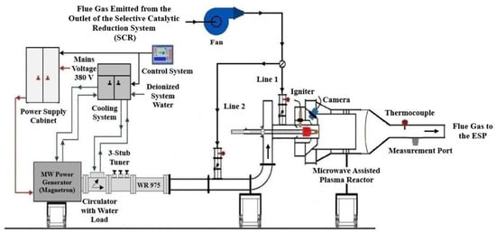
Figure 1.
Microwave-assisted plasma reactor system including auxiliary subsystems.
According to the process illustrated in Figure 1, the flue gas extracted from the outlet of the selective catalytic reduction system (SCR) by a fan is directed either through Line 1 or, depending on the position of the damper installed on it, transferred to Line 2 and subsequently conveyed to the microwave-discharge plasma reactor for SO2 treatment. The flue gas introduced through Line 1 enters the reactor in a radial direction, whereas the flue gas conveyed through Line 2 is introduced axially. Due to the cylindrical geometry of the reactor, the flue gas introduced radially into the reactor, as shown in Figure 2a via Line 1, flows from the reactor walls toward the central axis, resulting in an extended volumetric interaction time with the plasma flame. The flue gas entering axially from one end via Line 2 progresses along the central axis as shown in Figure 2b, comes into direct contact with the surface of the plasma flame, undergoes a reaction, and is subsequently discharged from the reactor.
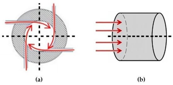
Figure 2.
(a) Radial flow of flue gas introduced into the reactor via Line 1; (b) axial flow of flue gas introduced into the reactor via Line 2.
Within the scope of this study, a series of experimental tests was performed to evaluate the influence of radial and axial flue gas injection into the reactor on SO2 removal performance. SO2 concentrations in the flue gas at the reactor inlet and outlet were measured and recorded using an MRU emission measurement device (MRU GmbH, Neckarsulm-Obereisesheim, Germany) via sampling ports positioned at Line 1, Line 2, and the reactor outlet. Each test was repeated five times, and the average values were used for evaluation. The flue gas temperatures are measured and recorded using K-type thermocouples installed at Line 1, Line 2, and the reactor outlet.
Microwave energy produced at a frequency of 915 MHz by a 75 kW magnetron (MUEGGE GmbH, Reichelsheim (Odenwald), Germany) is transmitted to the reactor via an interconnected series of rectangular waveguides, after being guided through a circulator and a three-stub tuner (MUEGGE GmbH, Reichelsheim (Odenwald), Germany). A WR 975 rectangular waveguide, characterized by a width of 247.65 mm and a height of 123.825 mm, is employed in the system. A circulator is employed to regulate the directionality of microwave signal propagation, allowing forward transmission while effectively isolating and preventing any reverse power flow.
The three-stub tuner is mounted between the reactor and the circulator. The supplied microwave power is absorbed at its maximum level, achieved by adjusting the tuner stubs to minimize reflected power. In the event of improper tuning, a fraction of the microwave energy is back-propagated and afterwards absorbed by the water load (MUEGGE GmbH, Reichelsheim (Odenwald), Germany) connected to the circulator, rather than being transferred to the plasma.
Four pumps, designed to operate at 6 bar pressure and rated at 0.75 kW, are incorporated into the cooling system. The water flow provided by these pumps serves to regulate the temperatures of the magnetron, circulator, water load, and power supply, thereby stopping thermal overload and ensuring stable operation of the system.
Stable plasma generation is ensured by a control system that monitors and adjusts the working parameters of the magnetron, power supply, and cooling system in real time. Electrical power is supplied to system components, primarily the magnetron, via the power supply cabinet, which also protects against electrical faults by interrupting the power flow in case of overloads or short circuits.
A tungsten rod with a diameter of 5 cm is placed along the central axis of the reactor. A secondary metallic rod, equipped with a copper tip and integrated into the igniter assembly, is pneumatically actuated to reciprocate through an aperture located at the upper section of the burner. Plasma initiation is achieved through spark generation, which occurs when the copper-tipped rod makes contact with the tungsten rod. To ensure stable and sustained plasma formation, the axial position of the copper-tipped rod is precisely calibrated along the reactor centerline.
A camera and a pyrometer, mounted on the reactor’s observation port, are utilized to enable real-time visual monitoring of the internal processes and to obtain precise temperature measurements of the flue gas-plasma flame.
3.2. Flue Gas Measurement Method
To determine the flow rates of the flue gas entering and exiting the reactor, the gas velocities were initially measured separately through the measurement ports installed at the reactor inlet and outlet. As the cross-sectional areas of the pipes are known, the velocities of the flue gases flowing through them can be determined accordingly. Accurate determination of flue gas velocities requires prior knowledge of the static pressure, differential pressure, and temperature developed during the gas flow within the pipe.
The measurement system was designed to enable accurate determination of both static and differential pressure within the flue gas duct. The pipe was prepared with a dedicated measurement port, through which the pressure probe could be inserted without disturbing the main gas flow. The probe was positioned perpendicular to the direction of the flue gas stream in order to minimize measurement bias caused by flow turbulence and to ensure representative data collection. Static pressure was obtained by aligning the probe openings parallel to the flow, while differential pressure was measured across the port using precision sensors. The entire setup was constructed and operated in strict compliance with the ASME PTC 4.2 standard [47], thereby ensuring that the acquired data meet internationally recognized accuracy and reliability requirements.
Furthermore, SO2 concentrations in the flue gas at the reactor inlet and outlet were monitored using an MRU emission measurement device through sampling ports located at Line 1, Line 2, and the reactor outlet. Corresponding flue gas temperatures were recorded using K-type thermocouples installed at the same locations.
4. Results and Discussion
As the first step of the experimental investigations, a series of tests was carried out to reduce the SO2 content of the flue gas introduced radially into the reactor through Line 1, as illustrated in Figure 1. The flue gas, extracted from the outlet of the selective catalytic reduction (SCR) system, was introduced into the reactor at a flow rate that was gradually increased up to 6000 Nm3/h through an electronically controlled fan. The temperature of the flue gas was recorded as 142 °C during the measurements.
In the tests conducted on the pulverized coal burner developed with microwave assistance [48], the minimum required flow rate of plasma-forming air for plasma flame generation was determined to be 500 Nm3/h. Accordingly, to generate a plasma flame from flue gas within the reactor, approximately 500 Nm3/h of flue gas was directed into the reactor. Subsequently, the magnetron power was adjusted to 18.75 kW, corresponding to 25% of its total capacity of 75 kW, and was maintained at this level, with the operating frequency set to 915 MHz. A spark was generated when the metal rod with a copper tip, actuated by a double-acting pneumatic valve operated with compressed air, was driven to strike the tungsten rod positioned at the center of the reactor. Plasma was generated at the center of the reactor as the flue gas, used as the working gas, was ionized by microwave energy through the initiation provided by the generated spark. The experimental setup used in these tests is shown in Figure 3.
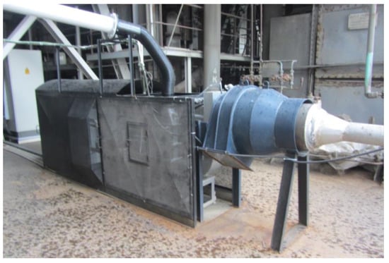
Figure 3.
Experimental Setup of the Microwave-Assisted Plasma Reactor.
After the formation of plasma, the magnetron power was increased to 37.5 kW, which is 50% of the total power. At this stage, the power of the electronically controlled fan extracting flue gas from the SCR system outlet was increased, and the flue gas flow rate was adjusted to reach 1485 Nm3/h, from an initial value of approximately 505 Nm3/h.
As shown in Table 6, when the magnetron output power was set to 37.5 kW, the SO2 concentration in the flue gas entering the reactor radially through Line 1 was measured to have decreased from 2201 mg/Nm3 to 85 mg/Nm3, corresponding to an SO2 removal efficiency of 96.1%. According to the formula given in (1), the SO2 removal efficiency was calculated based on these values. During this phase, a decrease in SO2 removal efficiency was observed when the flue gas flow rate induced by the fan was increased while keeping the magnetron output power constant. The SO2 removal efficiency (SO2 RE) was calculated with the following equations:
SO2 RE (%) = [1 − (SO2 outlet concentration, mg/Nm3/SO2 inlet concentration, mg/Nm3] × 100
Table 6.
Experimental parameters and results of SO2 removal tests in a microwave-assisted plasma system with radial flue gas injection.
During the subsequent phase of the experiments, the magnetron output ratio was increased by 10%, and the SO2 concentration in the flue gas extracted by the fan was measured after achieving maximum removal efficiency. The obtained results are presented in Table 6. At a magnetron output ratio of 100%, corresponding to a power level of 75 kW, a maximum SO2 removal efficiency of 99.0% was recorded for a flue gas flow rate of 5194 Nm3/h, radially introduced into the reactor by the fan. Before each SO2 removal test, adjustments were made to the three-stub tuner to minimize the reflected power.
In the second stage of the experimental investigations, a series of tests was conducted to reduce the SO2 content of the flue gas that was introduced axially into the reactor via Line 2, as illustrated in Figure 1. The flue gas, extracted from the outlet of the selective catalytic reduction (SCR), was introduced into the reactor through an electronically controlled fan at a flow rate of up to 6000 Nm3/h, and its temperature was recorded as 138 °C during the measurements.
Similar to the case in which the flue gas is introduced radially into the reactor, approximately 500 Nm3/h of flue gas is axially supplied to the reactor via an automatically regulated fan, where it is subsequently converted into plasma. After the formation of plasma, the magnetron power was increased to 37.5 kW, which is 50% of the total power. At this stage, the power of the electronically controlled fan extracting flue gas from the SCR system was increased, and the flue gas flow rate was adjusted to reach 1019 Nm3/h, from an initial value of approximately 510 Nm3/h.
As shown in Table 7, when the magnetron output power was set to 37.5 kW, the SO2 concentration in the flue gas entering the reactor axially through Line 2 was measured to have decreased from 1916 mg/Nm3 to 55 mg/Nm3, corresponding to an SO2 removal efficiency of 97.1%. According to the formula given in (1), the SO2 removal efficiency was calculated based on these values. During this phase, a decrease in SO2 removal efficiency was observed when the flue gas flow rate, induced by the fan, was increased while keeping the magnetron output power constant. During the subsequent phase of the experiments, the magnetron output ratio was increased by 10%, and the SO2 concentration in the flue gas extracted by the fan was measured after achieving maximum removal efficiency. The obtained results are presented in Table 7.
Table 7.
Experimental parameters and results of SO2 removal tests in a microwave-assisted plasma system with axial flue gas injection.
At a magnetron output ratio of 100%, corresponding to a power level of 75 kW, a maximum SO2 removal efficiency of 97.5% was recorded for a flue gas flow rate of 4100 Nm3/h, axially introduced into the reactor by the fan. Similar to the tests involving the radial introduction of flue gas into the reactor, adjustments to the three-stub tuner were made before each SO2 removal test to minimize reflected power.
Consequently, it was determined that, under radial injection of the flue gas into the reactor, the maximum SO2 removal efficiency reached 99% at a flue gas flow rate of 5194 Nm3/h with a microwave power of 75 kW. This corresponds to a specific energy consumption of 14.4 Wh/Nm3 of treated flue gas.
In contrast, under axial injection conditions, the highest SO2 removal efficiency of 97.5% was obtained at a flow rate of 4100 Nm3/h with the same power level of 75 kW, corresponding to a specific energy consumption of 18.3 Wh/Nm3.
In the case of radial injection, the experimental results demonstrated that the flue gas flow rate of 5194 Nm3/h with an inlet SO2 concentration of 2004 mg/Nm3 could be reduced to 20 mg/Nm3 at a microwave power of 75 kW, corresponding to a removal efficiency of 99.0%.
When the flue gas enters the plasma region, the surfaces of fly ash particles are bombarded by high-energy electrons and positive ions. Electrons, which move much faster, readily adhere to the particle surfaces, resulting in negative charging. At the same time, some ions also collide with the surfaces of fly ash particles, causing them to acquire positive charges. As a result of these bidirectional collisions, certain areas of the particle surfaces become negatively charged, while others become positively charged. Since particles carrying opposite charges attract each other electrostatically, this attractive force causes the fly ash particles to adhere to one another, leading to the formation of larger agglomerates. This phenomenon particularly facilitates the capture of fine particles (such as PM2.5) in electrostatic precipitator (ESP) systems.
On the other hand, the flue gas introduced into the reactor via radial feeding is conveyed to the electrostatic precipitator (ESP) at the reactor outlet in a homogeneous manner. By applying a direct current (DC) with a high voltage ranging from 20 to 70 kV to the wires inside the ESP, a corona discharge occurs from the discharge wires toward the collecting plates, as shown in Figure 4a.
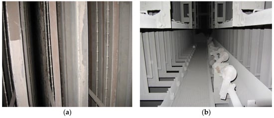
Figure 4.
(a) Image of the corona discharge region formed between the discharge wires and the collecting plates inside the electrostatic precipitator (ESP). (b) Periodic removal of deposited fly ash layers from the collecting plates through the mechanical rapping system.
This high voltage causes the gas molecules within the ESP to become ionized, resulting in the formation of negatively charged ions. The fly ash particles present in the flue gas collide with these ions and thereby acquire negative charges. The negatively charged fly ash particles then migrate toward the positively charged collecting electrodes inside the ESP under the influence of electrostatic forces.
As a result, the fly ash particles separated from the gas phase adhere to the surfaces of the collecting plates and are retained there. Since this process continues continuously during operation, a layer of ash gradually accumulates on the plate surfaces. The ash layers deposited on the plates are periodically removed by means of a mechanical rapping system Figure 4b, which dislodges the accumulated dust. Consequently, the detached ash particles fall into the ash hoppers located at the bottom of the ESP.
Before the magnetron generating microwave energy was activated, the flue gas produced from combustion in the boiler was directed to the electrostatic precipitator (ESP) after passing through the reactor. The microstructure of the fly ash samples, collected from the ESP hoppers after being captured on the collecting plates and dislodged by the mechanical rapping system, is shown in Figure 5a under a scanning electron microscope (SEM). As shown in Figure 5a, the majority of fly ash particles in the flue gas that passed through the reactor and were collected in the ESP before the magnetron was activated are smaller than 5 µm in size and exhibit a dispersed distribution.
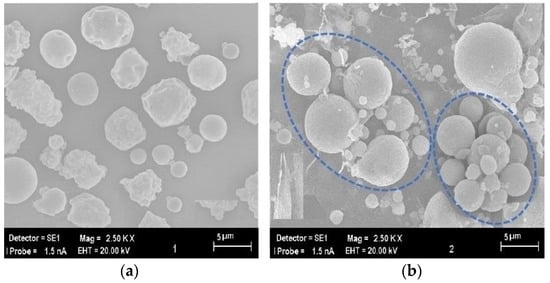
Figure 5.
Comparison of Micromorphology. (a) Raw Fly Ash Sample before Treatment (b) Fly Ash Samples Following Exposure to Microwave-Discharge.
On the other hand, Figure 5b presents the scanning electron microscope (SEM) image of the fly ash sample collected from the hoppers located at the bottom of the electrostatic precipitator (ESP) after the flue gas, which passed through the plasma formed inside the reactor upon activation of the magnetron, was directed to the ESP. Figure 5b reveals that the fly ash particles exposed to the plasma generated within the reactor tend to agglomerate with each other, resulting in the formation of larger particles exceeding 5 µm in size.
At this stage of the study, a sedimentation-based analysis was additionally conducted on the fly ash particles to determine the particle size distribution. Before the magnetron was activated, the fly ash particles present in the flue gas passing through the reactor were deposited on the collecting plates of the electrostatic precipitator (ESP). These particles were dislodged from the plates by means of the rapping system and collected in the hoppers located at the bottom of the ESP. The particle size distribution data of the samples obtained from these hoppers are presented in Table 8. As shown by the analysis results, the proportion of fly ash particles smaller than 2.5 µm is 70.25%, indicating a relatively high fraction. In other words, the PM2.5 content accounts for 70.25% of the total particles.
Table 8.
Particle size distribution of fly ash collected from the ESP before plasma activation (without magnetron operation).
The results presented in Table 9 indicate that after the activation of the magnetron and the formation of plasma within the reactor, the proportion of fine fly ash particles smaller than 2.5 µm (PM2.5), which are known to be harmful to human health, was measured as 18.63%.
Table 9.
Particle size distribution of fly ash collected from the ESP after plasma activation (with magnetron operation).
In Figure 6, the data on the undersize distribution of fly ash samples are presented for both plasma-on and plasma-off conditions. As observed from the graph, when the magnetron was activated, the fly ash particles in the flue gas passing through the plasma generated inside the reactor underwent agglomeration. Consequently, the proportion of particles smaller than 2.5 µm decreased from 70.25% to 18.63%.
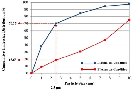
Figure 6.
Comparison of the undersize distribution of fly ash particles under plasma-on and plasma-off conditions.
This reduction demonstrates that the plasma promotes agglomeration of fine particles, leading to the formation of larger clusters that the ESP can more efficiently capture. PM2.5 particles are particularly hazardous because they can penetrate deeply into the respiratory tract and reach the alveolar regions of the lungs, causing respiratory and cardiovascular disorders. Therefore, the observed decrease in the PM2.5 fraction indicates not only an improvement in particulate removal efficiency but also a potential reduction in the health risks associated with fine particulate emissions.
5. Conclusions
This industrial-scale study verified that a plasma reactor, operating with 915 MHz microwave energy generated by a 75 kW magnetron and integrated downstream of the selective catalytic reduction (SCR) system at Unit-1 of the Soma A Thermal Power Plant (22 MWe), achieved high-efficiency SO2 removal under real operating conditions and modified the characteristics of fly-ash particles in a manner that enhances their collectability.
Two gas-injection configurations were evaluated. Under radial injection, the system achieved a 99.0% SO2 removal efficiency at 5194 Nm3/h with 75 kW, corresponding to a specific energy consumption of 14.4 Wh/Nm3. Under axial injection, the maximum efficiency reached 97.5% at 4100 Nm3/h with the same power, equivalent to 18.3 Wh/Nm3. These results indicate that radial injection offers both higher peak efficiency and lower specific energy consumption at the tested operating point.
SEM observations and particle size distribution analyses showed that exposure of fly ash to the microwave-discharge environment promotes agglomeration. The PM2.5 fraction decreased from 70.25% (pre-plasma) to 18.63% (post-plasma), indicating a substantial shift to larger sizes that the ESP can capture more efficiently. Beyond compliance, this compositional shift mitigates health-relevant fine particulates at the stack.
Stable operation was maintained via real-time tuning (three-stub tuner, circulator/water load management) and with reflected power minimized before each run. The electrode-free plasma source, compact reactor geometry, and modular architecture support retrofitability in space-constrained plants.
Consistent with sector practice, SCR remains the primary pathway for NOx removal, while the present results position microwave-discharge plasma as a high-efficiency SO2 stage with competitive energy intensity and without the secondary wastes (e.g., gypsum) inherent to WFGD.
Overall, microwave-discharge plasma offers a compact, modular, and potentially waste-free alternative for SO2 control at coal-fired units, now with demonstrated co-benefits for particulate control via agglomeration. These findings strengthen the case for deploying microwave-plasma reactors as part of practical, hybrid compliance architectures in industrial settings.
Funding
This research received no external funding.
Data Availability Statement
The original contributions presented in this study are included in the article. For further information, the author may be contacted.
Acknowledgments
The author would like to thank the staff of the Soma A Thermal Power Plant for their technical support provided within the scope of this project.
Conflicts of Interest
The author declares no conflicts of interest.
Abbreviations
| SO2 | Sulphur dioxide |
| NOx | Nitrogen oxides |
| ESP | Electrostatic precipitator |
| FGD | Flue gas desulfurization |
| WFGD | Wet flue gas desulfurization |
| SCR | Selective catalytic reduction |
| NTP | Non-thermal plasma |
| EB | Electron beam |
| PCD | Pulsed corona discharge |
| DBD | Dielectric barrier discharge |
| WR | Waveguide rectangular |
| ASME | American Society of Mechanical Engineers |
| mm WC | Millimeters of water column |
| Nm3 | Normal cubic meter |
| kWh | Kilowatt–hour |
| Wh | Watt–hour |
| PM | Particulate matter |
| PM2.5 | Particulate matter with an aerodynamic diameter ≤ 2.5 µm |
| mg | Milligram |
| °C | Celsius |
References
- Mochida, I.; Korai, Y.; Shirahama, M.; Kawano, S.; Hada, T.; Seo, Y.; Yoshikawa, M.; Yasutake, A. Removal of SOx and NOx over Activated Carbon Fibers. Carbon 2000, 38, 227–239. [Google Scholar] [CrossRef]
- Share of Electricity Production from Coal. Available online: https://ourworldindata.org/grapher/share-electricity-coal?tab=chart (accessed on 15 September 2024).
- Park, H.J.; Ahn, W.J.; Kim, H.K.; Son, S.Y. Historic and Futuristic Review of Electron Beam Technology for the Treatment of SO2 and NOx in flue gas. Chem. Eng. J. 2019, 355, 351–366. [Google Scholar] [CrossRef]
- Chmielewski, A.G. Industrial Applications of Electron Beam Flue Gas Treatment—From Laboratory to the Practice. Radiat. Phys. Chem. 2007, 76, 1480–1484. [Google Scholar] [CrossRef]
- Radoiu, T.M.; Martin, I.D.; Calinescu, I. Emission Control of SO2 and NOx by Irradiation Methods. J. Hazard. Mater. 2003, 97, 145–158. [Google Scholar] [CrossRef]
- Zhong, Y.; Gao, X.; Huo, W.; Luo, Z.Y.; Ni, M.J.; Cen, K. A Model for Performance Optimization of Wet Flue Gas Desulfurization Systems of Power Plants. Fuel Process. Technol. 2008, 89, 1025–1032. [Google Scholar] [CrossRef]
- Zhao, H.; Wu, T.; He, J.; Kingman, S.; Shi, K.; Shen, D.; Zhang, Y. Simultaneous Removal of SOX and NOX in Flue Gas at Power Stations over a Cu/Na-13X Zeolite Catalyst. Adv. Mater. Res. 2013, 650, 125–129. [Google Scholar] [CrossRef]
- Philip, L.; Deshusses, M.A. Sulfur Dioxide Treatment from Flue Gases Using a Biotrickling Filter—Bioreactor System. Environ. Sci. Technol. 2003, 37, 1978–1982. [Google Scholar] [CrossRef] [PubMed]
- Srivastava, R.K.; Jozewicz, W.; Singer, C. SO2 Scrubbing Technologies: A Review. Environ. Prog. 2001, 20, 219–228. [Google Scholar] [CrossRef]
- Qu, Z.; Yan, N.; Liu, P.; Chi, Y.; Jia, J. Bromine Chloride as an Oxidant to Improve Elemental Mercury Removal from Coal-Fired Flue Gas. Environ. Sci. Technol. 2009, 43, 8610–8615. [Google Scholar] [CrossRef]
- Zwolińska, E.; Gogulancea, V.; Sun, Y.; Lavric, V.; Chmielewski, A. A Kinetic Sensitivity Analysis for the SO2 and NOX Removal Using the Electron Beam Technology. Radiat. Phys. Chem. 2017, 138, 29–36. [Google Scholar] [CrossRef]
- Tan, E.; Ünal, S.; Doğan, A.; Letournel, E.; Pellizzari, F. New “Wet Type” Electron Beam Flue Gas Treatment Pilot Plant. Radiat. Phys. Chem. 2016, 119, 109–115. [Google Scholar] [CrossRef]
- Zhang, J.; Zhang, R.; Chen, X.; Tong, M.; Kang, W.; Guo, S.; Zhou, Y.; Lu, J. Simultaneous Removal of NO and SO2 from Flue Gas by Ozone Oxidation and NaOH Absorption. Ind. Eng. Chem. Res. 2014, 53, 6450–6456. [Google Scholar] [CrossRef]
- Basfar, A.A.; Fageeha, O.I.; Kunnummal, N.; Al-Ghamdi, S.; Chmielewski, A.G.; Licki, J.; Pawelec, A.; Tymiński, B.; Zimek, Z. Electron Beam Flue Gas Treatment (EBFGT) Technology for Simultaneous Removal of SO2 and NOx from Combustion of Liquid Fuels. Fuel 2008, 87, 1446–1452. [Google Scholar] [CrossRef]
- Subrahmanyam, C.; Renken, A.; Kiwi-Minsker, L. Catalytic Non-Thermal Plasma Reactor for Abatement of Toluene. Chem. Eng. J. 2010, 160, 677–682. [Google Scholar] [CrossRef]
- Mok, Y.S.; Ravi, V.; Kang, H.C.; Rajanikanth, B.S. Abatement of Nitrogen Oxides in a Catalytic Reactor Enhanced by Nonthermal Plasma Discharge. IEEE Trans. Plasma Sci. 2003, 31, 157–165. [Google Scholar] [CrossRef]
- Vandenbroucke, A.M.; Morent, R.; De Geyter, N.; Leys, C. Decomposition of Trichloroethylene with Plasma-Catalysis: A Review. J. Adv. Oxid. Technol. 2011, 14, 165–173. [Google Scholar] [CrossRef]
- Penetrante, B.M.; Bardsley, J.N.; Hsiao, M.C. Kinetic Analysis of Non-Thermal Plasmas Used for Pollution Control. Jpn. J. Appl. Phys. 1997, 36, 5007–5017. [Google Scholar] [CrossRef]
- McAdams, R. Prospects for Non-Thermal Atmospheric Plasmas for Pollution Abatement. J. Phys. D Appl. Phys. 2001, 34, 2810–2821. [Google Scholar] [CrossRef]
- Liu, Y.; Shan, Y.; Wang, Y. Novel Simultaneous Removal Technology of NO and SO2 Using a Semi-Dry Microwave Activation Persulfate System. Environ. Sci. Technol. 2020, 54, 2031–2042. [Google Scholar] [CrossRef]
- Wei, Z.S.; Zeng, G.H.; Xie, Z.R.; Ma, C.Y.; Liu, X.H.; Sun, J.L.; Liu, L.H. Microwave Catalytic NOx and SO2 Removal Using FeCu/Zeolite as Catalyst. Fuel 2011, 90, 1599–1603. [Google Scholar] [CrossRef]
- Balachandran, W.; Finst, P.; Manivannan, N.; Beleca, R.; Abbod, M. Reduction of NOx and PM in Marine Diesel Engine Exhaust Gas Using Microwave Plasma. J. Phys. Conf. Ser. 2015, 646, 012053. [Google Scholar] [CrossRef]
- Cheng, G.; Zhang, C. Desulfurization and Denitrification Technologies of Coal-fired Flue Gas. Pol. J. Environ. Stud. 2018, 27, 481–489. [Google Scholar] [CrossRef]
- Wang, W.; Zhao, Z.; Liu, F.; Wang, S. Study of NO/NOx Removal from Flue Gas Containing Fly Ash and Water Vapor by Pulsed Corona Discharge. J. Electrost. 2005, 63, 155–164. [Google Scholar] [CrossRef]
- Ma, H.; Chen, P.; Zhang, M.; Lin, X.; Ruan, R. Study of SO2 Removal Using Non-Thermal Plasma Induced by Dielectric Barrier Discharge (DBD). Plasma Chem. Plasma Process. 2002, 22, 239–254. [Google Scholar] [CrossRef]
- Kim, H.H. Nonthermal Plasma Processing for Air-Pollution Control: A Historical Review, Current Issues, and Future Prospects. Plasma Process. Polym. 2004, 1, 91–110. [Google Scholar] [CrossRef]
- Li, S.; Huang, Y.; Wang, F.; Liu, J.; Feng, F.; Shen, X.; Yan, K. Fundamentals and Environmental Applications of Non-Thermal Plasmas: Multi-Pollutants Emission Control from Coal-Fired Flue Gas. Plasma Chem. Plasma Process. 2014, 34, 579–603. [Google Scholar] [CrossRef]
- Li, R.; Liu, X. Main Fundamental Gas Reactions in Denitrification and Desulfurization from Flue Gas by Non-Thermal Plasmas. Chem. Eng. Sci. 2000, 55, 2491–2506. [Google Scholar] [CrossRef]
- Masuda, S.; Nakao, H. Control of NOx by Positive and Negative Pulsed Corona Discharges. IEEE Trans. Ind. Appl. 1990, 26, 374–383. [Google Scholar] [CrossRef]
- Zimek, Z. High Power Electron Accelerators for Flue Gas Treatment. Radiat. Phys. Chem. 1995, 45, 1013–1015. [Google Scholar] [CrossRef]
- Kogelschatz, U. Filamentary, Patterned, and Diffuse Barrier Discharges. IEEE Trans. Plasma Sci. 2003, 30, 1400–1408. [Google Scholar] [CrossRef]
- Lu, M.; Wang, X.; Pu, Y.; Guan, Z. Study of Atmospheric Pressure Glow Discharge. In Proceedings of the IEEE Conference Record—Abstracts. 2002 IEEE International Conference on Plasma Science (Cat. No.02CH37340), Banff, AB, Canada, 26–30 May 2002. [Google Scholar] [CrossRef]
- Talebizadeh, P.; Babaie, M.; Brown, R.; Rahimzadeh, H.; Ristovski, Z.; Arai, M. The Role of Non-Thermal Plasma Technique in NOx Treatment: A Review. Renew. Sustain. Energy Rev. 2014, 40, 886–901. [Google Scholar] [CrossRef]
- Hung, P.C.; Chang, S.H.; Chi, K.H.; Chang, M.B. Degradation of Gaseous Dioxin-like Compounds with Dielectric Barrier Discharges. J. Hazard. Mater. 2010, 182, 246–251. [Google Scholar] [CrossRef]
- Kogelschatz, U. Dielectric-Barrier Discharges: Their History, Discharge Physics, and Industrial Applications. Plasma Chem. Plasma Process. 2003, 23, 1–46. [Google Scholar] [CrossRef]
- An, J.; Shang, K.; Lu, N.; Hong, Y.; Jiang, Y.; Li, J.; Wu, Y. Performance of Dielectric Barrier Discharge Reactors on Elemental Mercury Oxidation in the Coal-Fired Flue Gas. Plasma Sci. Technol. 2014, 16, 155. [Google Scholar] [CrossRef][Green Version]
- Mizuno, A.; Clements, J.S.; Davis, R.H. A Method for the Removal of Sulfur Dioxide from Exhaust Gas Utilizing Pulsed Streamer Corona for Electron Energization. IEEE Trans. Ind. Appl. 2008, 3, 516–522. [Google Scholar] [CrossRef]
- Maezono, I.; Chang, J.S. Flow-Enhanced Corona Discharge: The Corona Torch. J. Appl. Phys. 1988, 64, 3322–3324. [Google Scholar] [CrossRef]
- Ohkubo, T.; Kanazawa, S.; Nomoto, Y.; Chang, J.S.; Adachi, T. NOx Removal by a Pipe with Nozzle-Plate Electrode Corona Discharge System. IEEE Trans. Ind. Appl. 1994, 30, 856–861. [Google Scholar] [CrossRef]
- Ohkubo, T.; Kanazawa, S.; Nomoto, Y.; Chang, J.S.; Adachi, T. Time Dependence of NOx Removal Rate by a Corona Radical Shower System. IEEE Trans. Ind. Appl. 2002, 32, 1058–1062. [Google Scholar] [CrossRef]
- Segawa, T.; Kawaguchi, K.; Ishii, K.; Suzuki, M.; Arimitsu, N.; Yoshida, H.; Fukui, K. Nickel Oxide Powder Synthesis from Aqueous Solution of Nickel Nitrate Hexahydrate by a Microwave Denitration Method. Adv. Powder Technol. 2015, 26, 983–990. [Google Scholar] [CrossRef]
- Doi, Y.; Nakanishi, I.; Konno, Y. Operational Experience of a Commercial-Scale Plant of Electron Beam Purification of Flue Gas. Radiat. Phys. Chem. 2000, 57, 495–499. [Google Scholar] [CrossRef]
- Licki, J.; Chmielewski, A.G.; Iller, E.; Zimek, Z.; Mazurek, J.; Sobolewski, L. Electron-Beam Flue-Gas Treatment for Multicomponent Air-Pollution Control. Appl. Energy 2003, 75, 145–154. [Google Scholar] [CrossRef]
- Chang, J.S.; Looy, P.C.; Nagai, K.; Yoshioka, T.; Aoki, S.; Maezawa, A. Preliminary Pilot Plant Tests of a Corona Discharge-Electron Beam Hybrid Combustion Flue Gas Cleaning System. IEEE Trans. Ind. Appl. 1996, 32, 131–137. [Google Scholar] [CrossRef]
- Ighigeanu, D.; Martin, D.; Zissulescu, E.; Macarie, R.; Oproiu, C.; Cirstea, E.; Iacob, N. SO2 and NOx Removal by Electron Beam and Electrical Discharge Induced Non-Thermal Plasmas. Vacuum 2005, 77, 493–500. [Google Scholar] [CrossRef]
- Junke, Z.; Xianwen, R.; Baojian, W.; Yan, W.; Ruizhuang, Y.; Guofeng, T.; Yabin, Z. Development of the PPCP Technology in IEPE. In Proceedings of the Electrostatic Precipitation: 11th International Conference on Electrostatic Precipitation, Hangzhou, China, 21–24 October 2008; Springer: Berlin/Heidelberg, Germany, 2009; Volume 11, pp. 1–5. [Google Scholar] [CrossRef]
- ASME. Fired Steam Generators. ASME PTC 4-2013. Google Scholar. 2013. Available online: https://scholar.google.com/scholar?hl=tr&as_sdt=2007&q=ASME.+2013.+Fired+Steam+Generators.+ASME+PTC+4-2013.+New+York%2C+NY%3A+ASME&btnG= (accessed on 12 January 2025).
- Tekir, U. Design and Experimental Study of a Novel Microwave-Assisted Burner Based on Plasma Combustion for Pulverized Coal Applications. Appl. Sci. 2025, 15, 5190. [Google Scholar] [CrossRef]


Disclaimer/Publisher’s Note: The statements, opinions and data contained in all publications are solely those of the individual author(s) and contributor(s) and not of MDPI and/or the editor(s). MDPI and/or the editor(s) disclaim responsibility for any injury to people or property resulting from any ideas, methods, instructions or products referred to in the content. |
© 2025 by the author. Licensee MDPI, Basel, Switzerland. This article is an open access article distributed under the terms and conditions of the Creative Commons Attribution (CC BY) license (https://creativecommons.org/licenses/by/4.0/).