Abstract
Addressing the challenges of high cost and complex configuration in conventional circulating fluidized bed (CFB) gasification-boiler systems, which stem from their reliance on auxiliary cooling and pressurization units, this paper proposes a novel solution. The approach involves the direct feeding of high-temperature syngas from a biomass CFB gasifier into a gas-fired boiler for combustion. This design not only fundamentally circumvents the problem of tar condensation but also renders the auxiliary systems unnecessary, resulting in a significant reduction in investment and operational expenses. Taking a biomass CFB gasifier coupled with a 20 t/h gas-fired steam boiler system (in Jiangsu Province, China) as a case study, this paper analyzes the main problems encountered during the commissioning period in the gasifier and gas-fired boiler, including slagging in the gas-fired boiler furnace, ash deposition on the tail heating surface of the gas-fired boiler and elevated exhaust gas temperature, air leakage at the lower part of the gasifier’s secondary cyclone separator, and insufficient capacity of the spiral ash cooler. Effective improvement measures are proposed. These findings provide valuable references for coupling biomass CFB gasifiers with industrial boilers and offer practical guidance for scaling up biomass CFB gasification technology.
1. Introduction
As the world’s fourth-largest primary energy source following coal, oil, and natural gas, biomass energy demonstrates unique advantages in addressing climate change and energy security challenges due to its renewable nature and carbon-neutral characteristics. China, being a leading agricultural producer, generates approximately 3.49 billion tonnes of biomass resources annually [1], including agricultural/forestry residues and livestock manure. The efficient utilization of these resources holds strategic significance for mitigating energy supply–demand imbalances, reducing carbon emissions, and advancing circular agricultural economies.
Biomass gasification technology converts biomass into value-added gaseous fuels such as hydrogen, carbon monoxide, and methane. These syngas products serve as industrial feedstocks for power generation, thermal energy production, hydrogen extraction, and liquid fuel synthesis [2]. This approach not only reduces reliance on conventional fossil fuels but also supports industrial decarbonization needs for downstream processes like biohydrogen production and green methanol synthesis [3]. As the core equipment, biomass gasifiers are categorized into four types: fixed-bed, bubbling fluidized bed (BFB), pressurized fluidized bed (PFB), and circulating fluidized bed (CFB). Fixed-bed and BFB gasifiers face challenges including low syngas yield and fouling issues [4]. PFB gasification enhances gasification intensity, reaction rate, and reduces equipment footprint. However, achieving stable feedstock supply under pressure remains challenging [5]. In contrast, CFB gasification demonstrates superior performance in gas yield, carbon efficiency, and scalability [6], making it more suitable for large-scale industrial implementation.
Current research on biomass CFB gasification technology focuses on optimizing process parameters (e.g., temperature, solid-to-gas ratio, fluidization velocity) to enhance syngas quality, and developing cost-effective, highly reliable system integration solutions. Zhang et al. [7] investigated CO2 reduction feasibility in a pilot-scale biomass CFB gasifier, examining the effects of gasification agent parameters (CO2 substitution for N2, O2 concentration, and oxygen-to-carbon ratio). Results demonstrated successful CO2 reduction with higher CO yield under O2/CO2 atmospheres compared to air atmospheres. Yang et al. [8] established a Multiphase Particle-in-Cell (MP-PIC) model to simulate olive waste gasification in a pilot-scale full-loop CFB reactor. Their exploration of solid-phase heat transfer characteristics and operational parameter impacts on thermochemical properties provides critical insights for optimizing CFB gasifier design and operation. Kartal et al. [9] developed a novel CFB gasifier model in Aspen HYSYS, evaluating steam/CO2 gasification characteristics of biochar. The study assessed operating parameter effects on syngas composition and compared gasification performance across ten biochar samples with distinct physicochemical properties. These findings primarily derive from small-scale or pilot systems. Due to limited reaction times and significant heat losses, the gasification behavior observed differ substantially from those in large-scale industrial installations.
Current applications of large-scale industrial biomass CFB gasifiers exhibit distinct regional patterns: In the United States and Brazil, they primarily produce biofuels, while in Europe and Asia they are predominantly coupled with coal-fired power plant boiler systems for generating electricity, heat, or syngas. Europe demonstrates particularly widespread adoption. For instance, the Kymijärvi II gasification plant in Lahti, Finland—Europe’s largest operational facility—features two 80 MW CFB gasifiers. The produced syngas undergoes cooling and filtration before being fed into a natural-circulation steam boiler (12.1 MPa, 540 °C) to generate 50 MW of electricity and 90 MW of thermal energy [10]. The Netherlands’ largest operational unit is the 85 MW CFB wood gasifier at the Amer-9 plant. Integrated with a 600 MW coal-fired power station operating approximately 5000 h annually, this facility experienced operational interruptions during its service due to conveying system failures and tar contamination [11]. Similarly to the aforementioned processes, large-scale industrial biomass CFB gasifiers in China are predominantly coupled with coal-fired boilers for power generation. Representative installations include a 10.8 MW biomass CFB gasifier integrated with a 640 MW coal-fired unit at Guodian Changyuan Jingmen Power Plant, a 20 MW slightly pressurized biomass CFB gasifier coupled to a 660 MW supercritical boiler at Datang Changshan Thermal Power Plant [12], and a 30 MW biomass CFB gasifier connected to a 600 MW supercritical coal-fired power generation unit at a Hubei-based power station [13].
In such configurations, high-temperature syngas must be cooled before combustion in the coal-fired boiler. The gas cooling system—a closed pressurized circuit—comprises high-pressure heat exchangers, thermal oil circulation pumps, steam sootblowers, and filtration units. This reduces syngas temperature from 700 to 800 °C to 400–420 °C through heat recovery [14]. The cooled syngas is then pressurized via booster fans and transported through main/auxiliary pipelines to the furnace. This integrated cooling and pressurization infrastructure introduces significant complexity and costs. Consequently, the technology remains economically unviable for most small-to-medium-sized industrial boilers.
A facility in Jiangsu Province, China has implemented a novel CFB gasifier-coupled gas-fired steam boiler system. High-temperature syngas (700–800 °C) from a 5 t/h gasifier is directly fed—without cooling—into the burner atop a 20 t/h gas-fired steam boiler for steam production. This configuration eliminates complex gas cooling and filtration subsystems, significantly simplifying equipment and reducing capital costs. The complete thermal decomposition of tars at combustion temperatures eliminates tar-related issues while utilizing tar’s calorific value. This system demonstrates efficient biomass resource utilization and validates the technical feasibility of coupling biomass gasification with industrial gas-fired boilers. However, during the system commissioning process, problems such as slagging in the furnace of the gas-fired boiler and ash deposition on the tail heating surfaces emerged. In the recovery process of high-temperature gasification ash (at approximately 800 °C), issues including air leakage at the lower part of the secondary cyclone separator of the gasifier and insufficient capacity of the spiral ash cooler arose. Therefore, based on this operational experience, this paper documents identified issues and implemented improvement measures, providing actionable insights to facilitate large-scale deployment of biomass CFB gasifier-steam boiler integrated systems across China.
2. Equipment Overview
A biomass CFB gasification coupled with gas-fired steam boiler system was constructed at a factory in Jiangsu Province, China. Biomass is gasified in the gasifier to produce combustible gas, which is then fed into the gas-fired steam boiler system to generate saturated steam at 1.57 MPa and 201 °C. The gasifier adopts a circulating fluidized bed structure with a square furnace, composed of membrane water walls and externally lined castables. Rice husk is used as the feedstock for the gasifier, and its composition is presented in Table 1. Quartz sand serves as the fluidizing medium. Both the biomass feeding system and the quartz sand feeding system are installed at the front of the furnace. The gasifier is equipped with primary and secondary cyclone separators. A loop seal is installed below the primary cyclone separator to recycle materials back to the furnace. The secondary cyclone separator is designed for separating high-temperature biomass ash, with ash coolers placed underneath. Fine rice husk ash is cooled, collected, and transported outward, while the separated fuel gas is directly sent to the gas-fired boiler for combustion.

Table 1.
Proximate and ultimate analysis of rice husk (Mass fraction, %).
The gas-fired steam boiler (hereinafter referred to as the gas-fired boiler) adopts membrane water walls. Gas burners are arranged in the upper part of the furnace, and evaporative heating surfaces are placed in the lower part. Downstream, there are the successively arranged superheater, high-temperature economizer, high-temperature air preheater, low-temperature economizer, and low-temperature air preheater. The boiler is a vertical two-pass boiler with a “U”-shaped layout. The structural schematic diagram of the biomass CFB gasification coupled with gas-fired steam boiler system is shown in Figure 1, and the main design parameters are listed in Table 2.
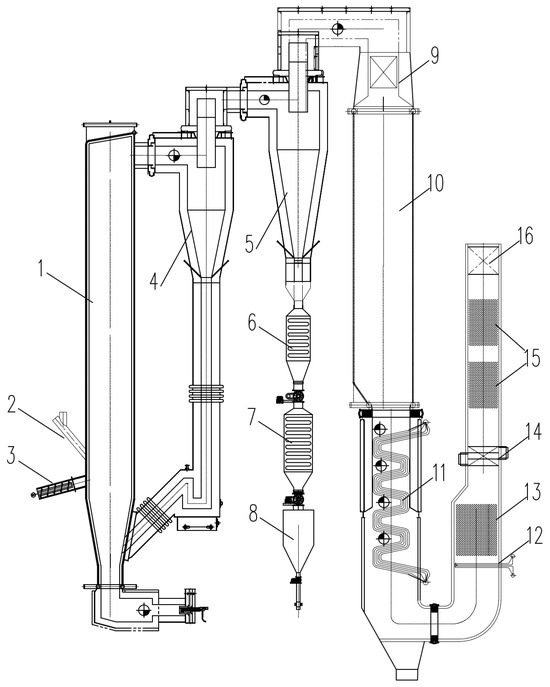
Figure 1.
Schematic diagram of the biomass CFB gasification coupled with gas-fired steam boiler system. (1) Furnace of biomass CFB gasifier; (2) quartz sand feeder; (3) biomass feeder; (4) primary cyclone separator; (5) secondary cyclone separator; (6) primary water-cooled ash silo; (7) secondary water-cooled ash silo; (8) transfer silo; (9) gas burner; (10) furnace of gas-fired steam boiler; (11) evaporative heating surface; (12) superheater; (13) high-temperature economizer; (14) high-temperature air preheater; (15) low-temperature economizer; (16) low-temperature air preheater.
Table 2.
Main design parameters of the biomass CFB gasification coupled with gas-fired steam boiler system.
This system bypasses conventional gas cleaning steps by directly feeding high-temperature biomass syngas from a CFB gasifier into a gas-fired boiler. The tars in the syngas are combusted and decomposed. This design fundamentally resolves issues associated with tar condensation in biomass syngas, such as pipe blockages and fouling on heat exchange surfaces. Moreover, the system eliminates the need for auxiliary syngas cooling and pressurization systems, thereby significantly reducing both capital investment and operational costs. However, during the system commissioning process, problems such as slagging in the furnace of the gas-fired boiler, ash deposition on the tail heating surfaces and insufficient capacity of the spiral ash cooler emerged. The methods detailed in Table 3 were adopted to address the aforementioned issues. Improvement measures using the methodology in Table 3 are detailed in Section 3.
Table 3.
Main issues during the system commissioning process of the biomass CFB gasification coupled with gas-fired steam boiler system and issues resolution methodology.
3. Main Problems and Improvement Measures
3.1. Slagging in the Gas-Fired Boiler Furnace
During combustion in the gas-fired boiler, clearly visible localized slagging occurred around the burner and on the water-cooled walls of the furnace. Clearly visible ash-colored slag deposited adhere to the burner outlet edges and the upper sections of the water-cooled walls (Figure 2a). Similar white, slag-like blocky accumulations were observed at inspection ports on the upper water-cooled walls and other locations (Figure 2b). The slagging in the boiler furnace primarily results from the combined effects of fuel properties and combustion conditions. This boiler uses biomass syngas produced by an upstream CFB gasifier. CFB gasifiers typically exhibit lower carbon conversion rates than direct combustion furnaces of equivalent capacity, leading to higher rice husk ash content in the biomass syngas compared to conventional direct biomass combustion. Rice husk ash primarily consists of SiO2, KCl, K2O, and other compounds that significantly influence ash fusion temperature [15]. This unremoved ash enters the furnace with the fuel gas, rapidly increasing the K2O and Cl content in the deposited ash and substantially lowering the ash fusion temperature. Furthermore, due to the unique design of the boiler system, the high-temperature biomass syngas (approximately 800 °C) from the gasifier was fed directly into the boiler burner without cooling. During operation, the high flame center temperature at the burner outlet and the upper water-cooled walls facilitates the formation of low-melting-point compounds such as KAl2(AlSi3O10)(OH)2 and K(AlSi3O8) from K2O, Cl, and SiO2 at elevated temperatures [16]. This causes ash particles to melt and adhere to the surfaces of the water-cooled wall tubes and burner outlet, where they continuously accumulate, forming slag deposits.
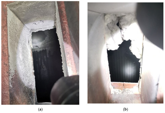
Figure 2.
Slagging in the gas-fired boiler furnace: (a) Burner outlet and top of water-cooled walls; (b) Upper water-cooled wall peephole.
Effective prevention of furnace slagging can be achieved by reducing the carbon content in biomass gas to lower ash levels, or by minimizing the accumulation of rice husk ash on burners and water-cooled furnace walls. Therefore, to address the furnace slagging issue, the following measures can be implemented:
(1) Appropriately reduce the carbon content in the biomass gas. Lowering the carbon content can help mitigate furnace slagging. This can be achieved by optimizing the gasifier’s control strategy, such as adjusting the fuel–air mixture ratio to moderately increase bed temperature and raise the bed differential pressure. Research indicates that during biomass gasification, a higher bed temperature promotes more complete particle gasification, reducing the unburned carbon content in fly ash [13]. Increasing the bed differential pressure (bed material thickness) reduces the gas flow velocity, extends particle residence time for more thorough gasification, lowers the fluidization velocity, and enhances cyclone separator efficiency. Collectively, this improves carbon conversion and reduces fly ash carbon content [17].
(2) Install steam sootblowers. Eight steam sootblowers were installed in the upper-middle section of the gas-fired boiler furnace: two levels, with one unit positioned on each of the four walls’ water-cooled surfaces per level. Regular soot blowing of the furnace heating surfaces will remove accumulated rice husk ash promptly, preventing further sintering into slag. The optimal soot blowing frequency and duration was determined based on operating conditions, such as gas flow rate, furnace temperature, and ash content. Concurrently, regular inspections should be performed to ensure the sootblowers are functioning correctly. Should any malfunction occur, prompt repair or replacement is essential.
The results indicate that both increasing the gasifier bed temperature and raising the material layer differential pressure contributed to a reduction in furnace coking in the gas furnace. When the material layer differential pressure was maintained at 7000 Pa and the gasifier bed temperature was raised from 750 °C to 800 °C, a significant improvement in slagging was observed. Only minor slagging occurred at the burner outlet and the top of the water-cooled wall, with small coke fragments present at the inspection ports. However, when the gasifier bed temperature was increased from 800 °C to 850 °C, significant slagging occurred in the combustion furnace. The primary cause is suspected to be the excessive temperature, which melted the rice husk ash entrained in the syngas, causing it to stick to the furnace walls. Consequently, the optimal bed temperature was determined to be 800 °C. When the gasifier bed temperature was held at around 800 °C and the material layer differential pressure was increased from 7000 Pa to 7500 Pa, the improvement in slagging was less pronounced. The coke blocks found at the water-cooled wall inspection ports were larger than those under the elevated temperature condition. Further increases in the bed pressure drop yielded diminishing returns in slagging mitigation. Consequently, the optimal value was established at 7500 Pa. Increasing the gasifier bed temperature proved more effective in mitigating slagging than raising the material layer differential pressure. Without the use of sootblowers, minor slagging will still develop over time, even with optimized gasifier parameters. Through these adjusted gasification control strategies, coupled with regular soot blowing, no slagging was observed in the gas furnace.
3.2. Ash Deposition on the Tail Heating Surface of the Gas-Fired Boiler and Elevated Exhaust Gas Temperature
An issue of severe ash deposition on the tail heating surface was observed during the load increase of the gas-fired boiler. This led to a flue gas temperature of 176 °C, which is well above the design specification (130 °C). When at 17 t/h load (boiler outlet temperature 760 °C), ash accumulation occurred on the upper convection tube bundle, with slag fragments falling in the furnace. The ash exhibited a sticky consistency (Figure 3a). When at 14 t/h load (boiler outlet temperature 710 °C), ash accumulation on the upper convection tube bundle was significantly reduced, with the ash appearing powdery. Post-shutdown inspection revealed no ash or slag in the central zone of the convection tube bundle but identified numerous spalled ash chunks from the surrounding water-cooled walls. Significant ash accumulation was also observed in the mid-section of the convection tube bundle (Figure 3b), likely caused by slag fragments dislodged during upper-bundle cleaning operations falling and accumulating in this area, thereby exacerbating ash deposition. After three days of operation, severe ash accumulation developed in the high-temperature economizer (Figure 3c), causing an approximate 300 Pa increase in differential pressure. The economizer’s staggered tube arrangement with narrow gaps prevented the passage of slag fragments dislodged during prior convection tube bundle cleaning operations, thereby worsening ash deposition. Furthermore, persistently high exhaust gas temperatures reduced overall boiler system efficiency, which increased fuel consumption and subsequently caused a sharp rise in ash content within the biomass gas. The presence of elevated levels of alkali metals and chlorine in biomass ash leads to ash-related issues such as slagging and fouling [18]. Thus, the elevated ash level intensified furnace slagging and ash fouling, while increased blockage in rear heating surfaces, further impaired heat absorption. Consequently, exhaust temperatures rose further, establishing a self-reinforcing cycle.
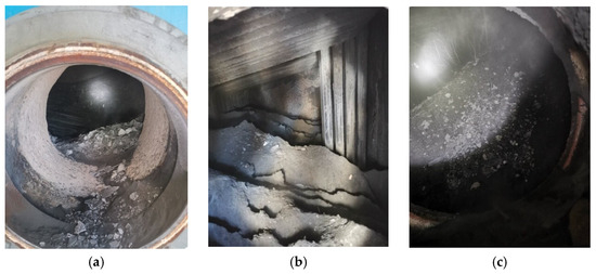
Figure 3.
Ash accumulation in the tail heating surface of the gas-fired boiler: (a) Upper convection tube bundle; (b) Mid-section convection tube bundle; (c) High-temperature economizer inlet.
By increasing the flow passage cross-section of the tail heating surfaces, optimizing the spatial layout of the tail heating surfaces and sootblowers, and reducing fly ash deposition in the tail heating surfaces, heating surface fouling and high exhaust gas temperature issues can be effectively mitigated. To address ash accumulation in the tail heating surfaces, the following measures can be implemented:
(1) Increase flow cross-section of the tail heating surfaces and enhance heat transfer intensity to reduce exhaust gas temperatures. An increase in the transverse pitch can effectively mitigate the degradation of heat transfer efficiency in the tail heating surface tube bundles caused by ash fouling [19]. The pitch of convection water-cooled tube bundles was expanded from 85 mm to 150 mm. The net bundle pitch of the convective tube bundle increased from 34 mm to 99 mm. To compensate for the reduction in heat transfer capacity caused by the pitch enlargement, the convection bundle heat transfer area was expanded from 111 m2 to 210 m2 by adding transverse tube rows. Concurrently, the high-temperature economizer heat transfer area was increased from 50 m2 to 220 m2 to ensure post-retrofit exhaust temperatures meet design requirements. Comparative parameters of heating surfaces pre- and post-retrofit are shown in Table 4. Due to the higher ash content in biomass syngas relative to direct biomass combustion, achieving an equivalent flue gas temperature necessitates significantly larger flow areas in the heat exchange sections. Specifically, the convective tube bundle must be expanded by a factor of approximately two, and the high-temperature economizer by a factor of approximately four, compared to direct biomass firing under the same conditions.
Table 4.
Key parameters of the tail heating surfaces pre- and post-retrofit.
(2) Optimize the spatial arrangement of sootblowers in the rear duct and enhance the self-cleaning capability of the rear heating surfaces. To free up space for the convection tube bundle arrangement, the existing SCR reactor module was removed. The high-temperature economizer and superheater were relocated to the former SCR location within the rear duct. Sootblowers throughout the rear duct were reconfigured. Existing acetylene weak-explosion units were repositioned. Two sootblowers were moved to the mid-section of the convection tube bundle, one unit was positioned at the high-temperature economizer mid-section, and two units were transferred to the low-temperature economizer mid-section. Acoustic sootblowers were shifted to the low-temperature air preheater zone. The schematic diagrams of heating surfaces pre- and post-retrofit are presented in Figure 4.
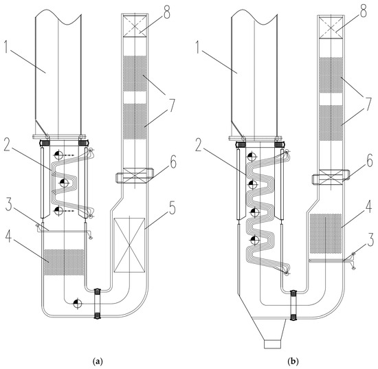
Figure 4.
Schematic of the tail heating surfaces arrangement: (a) Pre-retrofit; (b) Post-retrofit. (1) Furnace of gas-fired steam boiler; (2) evaporative heating surface; (3) superheater; (4) high-temperature economizer; (5) former SCR location; (6) high-temperature air preheater; (7) low-temperature economizer; (8) low-temperature air preheater.
Following the modifications, a post-operation inspection after a full cycle revealed that the convection water-cooled tube bundles and high-temperature economizer were virtually unobstructed by ash, with only minor ash accumulation in areas inaccessible to the sootblowers. Throughout the cycle, the exhaust gas temperature of the gas furnace remained stable between 120 and 127 °C, aligning closely with the theoretically calculated value of 121 °C presented in Table 4.
3.3. Air Leakage at the Lower Part of the Gasifier’s Secondary Cyclone Separator, and Insufficient Capacity of the Spiral Ash Cooler
During operation, agglomeration occurred in the rice husk ash which was fed to the negative-pressure ash conveying pipeline. The rice husk ash temperature was measured between 380 °C and 430 °C, significantly exceeding the design value of 200 °C. This issue is attributed to two primary causes: an air leakage at the bottom of the secondary cyclone in the gasifier, and insufficient capacity of the spiral ash cooler.
The biomass CFB gasifier bed temperature was controlled at approximately 700–800 °C, with both stages of cyclone separators featuring adiabatic designs. Consequently, the high-temperature gasification ash separated by the secondary cyclone separator remained at about 700–800 °C, carrying combustible gasification syngas at similar temperatures. During commissioning, air leakage occurred at the connection between the lower section of the secondary cyclone separator and the spiral ash cooler. Partial combustion of biomass syngas and hot ash at this location caused ash agglomeration and further temperature rise. Concurrently, the spiral ash cooler demonstrated insufficient capacity, resulting in ash temperatures at the outlet exceeding the design threshold (200 °C) and surpassing the tolerance limits of the negative-pressure ash conveying pipeline.
To address the aforementioned issues, it is essential to implement effective measures that minimize air leakage in the ash cooler and increase its cooling capacity. Therefore, the following measures were implemented:
(1) A primary water-cooled ash silo was installed at the secondary cyclone separator outlet. Designed to hold one hour’s worth of ash volume, the silo provides substantial buffer capacity. Equipped with an internal high-efficiency water-cooled heat exchanger, the silo cools hot gasification ash from 700 to 800 °C to approximately 600 °C, thereby effectively reducing the thermal load on downstream equipment.
(2) The spiral ash cooler was replaced with a secondary water-cooled ash silo positioned above the existing transfer silo, whose lower section connects to the current negative-pressure ash conveying pipeline. This vertically stacked silo configuration optimizes spatial efficiency while enabling staged cooling and sequential transfer of ash material. The retrofit secondary water-cooled silo maintains the water-cooling mechanism, further stabilizing ash temperatures to ensure discharge temperatures comply with equipment safety thresholds.
(3) Intelligent wall vibrators were installed on each silo’s interior surface to prevent material accumulation and bridging inside silos. These units automatically adjust vibration frequency and intensity based on real-time ash level and material properties, ensuring unimpeded flow while enhancing operational stability and reliability throughout the ash handling system. Comparative schematics of the ash cooling system pre- and post-retrofit are shown in Figure 5.
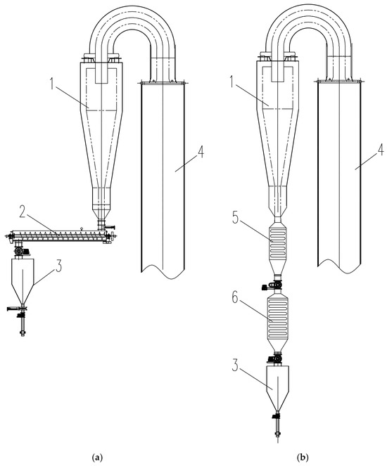
Figure 5.
Schematic of the ash cooling system: (a) Pre-retrofit; (b) Post-retrofit. (1) Secondary cyclone separator of biomass CFB gasifier; (2) spiral ash cooler; (3) transfer silo; (4) furnace of gas-fired steam boiler; (5) primary water-cooled ash silo; (6) secondary water-cooled ash silo.
Following the modifications, the ash temperature at the outlet of the secondary water-cooled ash silo remained stable between 204 and 249 °C throughout the operational cycle. This temperature range is within the tolerance of the negative-pressure ash conveying pipelines, ensuring stable operation of the ash handling system.
4. Conclusions
The direct combustion of 800 °C gasification gas eliminated complex cooling systems and tar issues, enhancing economic viability. This paper demonstrates the technical feasibility of integrating biomass CFB gasifier with gas-fired boiler via direct combustion of high-temperature biomass gasification gas, while identifying critical operational challenges: furnace slagging, tail heating surface fouling in gas-fired boiler, and insufficient ash cooling capacity in the CFB gasifier. Implementation of targeted measures—reducing biomass syngas carbon content, optimizing sootblower deployment, enlarging the flow cross-sections of tail heating surfaces, and adopting multi-stage ash cooling with intelligent vibrators—significantly mitigated these issues. Moderately increasing the gasifier’s operating parameters, such as adjusting the bed temperature from 750 °C to 800 °C and adjusting the bed pressure drop from 7000 Pa to 7500 Pa, can effectively mitigate slagging in the combustion furnace. To maintain a target flue gas temperature, the required flow area for the convective tube bundle when firing syngas is about double, while that for the high-temperature economizer is about quadruple, relative to the baseline of direct biomass combustion. These engineering solutions validate the system’s reliability for industrial-scale deployment, offering a replicable pathway for sustainable biomass utilization in small-to-medium industrial settings, with particular relevance to China’s agricultural waste valorization initiatives.
Author Contributions
Investigation, S.G. and W.Z.; writing—original draft preparation, S.G.; writing—review and editing, X.L. and L.Y. All authors have read and agreed to the published version of the manuscript.
Funding
This research was funded by the “Nanxun Scholars Program for Young Scholars of ZJWEU”, grant number RC2022021036, and the “Science and Technology Project of Water Resources Department of Zhejiang Provincial”, grant number RB2208.
Data Availability Statement
The original contributions presented in this study are included in the article. Further inquiries can be directed to the corresponding author.
Acknowledgments
The financial support from the “Nanxun Scholars Program for Young Scholars of ZJWEU” and Nanxun Innovation Institute is kindly acknowledged.
Conflicts of Interest
Author Weijun Zhu was employed by the Taizhou Power Plant, Zhejiang Zheneng Electric Power Co., Ltd. Author Xiaoye Liang was employed by the China Energy Engineering Group Zhejiang Electric Power Design Institute Co., Ltd. The remaining authors declare that the research was conducted in the absence of any commercial or financial relationships that could be construed as a potential conflict of interest.
References
- Ding, H.; Zhu, Z. Research hotspots and development trends of domestic biomass thermochemical conversion. Low Carbon Chem. Chem. Eng. 2025, 6, 1–10, (In Chinese with English abstract). [Google Scholar] [CrossRef]
- Wang, L.; Weller, C.L.; Jones, D.D.; Hanna, M.A. Contemporary issues in thermal gasification of biomass and its application to electricity and fuel production. Biomass Bioenerg. 2008, 32, 573–581. [Google Scholar] [CrossRef]
- Wang, L.; Zhou, T.; Hou, B.; Yang, H.; Hu, N.; Zhang, M. A comprehensive review of biomass gasification characteristics in fluidized bed reactors: Progress, challenges, and future directions. Fluids 2025, 10, 147. [Google Scholar] [CrossRef]
- Liu, N.; Liu, Z.; Wang, Y.; Zhou, T.; Zhang, M.; Yang, H. Clean and efficient thermochemical conversion technologies for biomass in green methanol production. Biomass 2025, 5, 13. [Google Scholar] [CrossRef]
- Zhu, X. Numerical Simulation and Experimental Study on Gas-Solid Flow Characteristics in Pressurized Fluidized Beds; University of Chinese Academy of Sciences: Beijing, China, 2020. [Google Scholar]
- Guo, F.; Dong, Y.; Dong, L.; Jing, Y. An innovative example of herb residues recycling by gasification in a fluidized bed. Waste Manage 2013, 33, 825–832. [Google Scholar] [CrossRef]
- Zhang, S.; Liang, C.; Wang, X.; Zhu, Z. Experimental study and equilibrium analysis on thermal reduction of CO2 by CFB gasification. J. Energy Inst. 2024, 115, 101623. [Google Scholar] [CrossRef]
- Yang, S.; Liang, J.; Wang, S.; Wang, H. High-fidelity investigation of thermochemical conversion of biomass material in a full-loop circulating fluidized bed gasifier. Energy 2021, 224, 120093. [Google Scholar] [CrossRef]
- Kartal, F.; Sezer, S.; Ozveren, U. Investigation of steam and CO2 gasification for biochar using a circulating fluidized bed gasifier model in Aspen HYSYS. J. CO2 Util. 2022, 62, 102078. [Google Scholar] [CrossRef]
- Hrbek, J. Status Report on Thermal Biomass Gasification in Countries Participating in IEA Bioenergy Task 33; IEA Bioenergy: Paris, France, 2016; Available online: http://task33.ieabioenergy.com/content/Task%2033%20Projects (accessed on 1 April 2016).
- Ma, W.; Sheng, C. Application status of indirect biomass co-firing power generation technologies based on circulating fluidized bed gasification. Therm. Power Gen. 2019, 48, 1–7, (In Chinese with English abstract). [Google Scholar] [CrossRef]
- Su, X.; Liu, J.; Chen, G.; Yao, J.; Yan, B.; Yi, W.; Cheng, Z.; Yao, Y.; Liu, X.; He, J.; et al. Progress in coal-coupled biomass gasification technology for power generation. J. China Coal Soc. 2023, 48, 2261–2278, (In Chinese with English abstract). [Google Scholar] [CrossRef]
- Fan, X.; Yang, L.; Jiang, J. Experimental study on industrial-scale CFB biomass gasification. Renew. Energ. 2020, 158, 32–36. [Google Scholar] [CrossRef]
- Dionisis, S.; Athanasios, N.; Konstantina, K.; Aristeidis, N.; Nikolaos, N.; Jens, P.; Jochen, S.; Bernd, E. Simulation of a CFB boiler integrated with a thermal energy storage system during transient operation. Front. Energy Res. 2020, 8, 169. [Google Scholar] [CrossRef]
- Gu, S.; Liu, M.; Liang, X. Analysis of operational problems and improvement measures for biomass-circulating fluidized bed gasifiers. Energies 2024, 17, 303. [Google Scholar] [CrossRef]
- Yongzheng, W.; Bo, L.; Yanjie, L.; Wenjie, F.; Jisen, L.; Shengli, N.; Kuihua, H. Investigation on the mechanism of ash deposition formation from mineral components and characteristics of ash deposition on boiler heating surface during co-firing of coal and biomass. J. Energy Inst. 2025, 118, 101921. [Google Scholar] [CrossRef]
- Gong, S.; Jiang, Y.; Zhang, B. Research on the operating characteristics of circulating fluidized bed with high oxygen content. Electr. Power Surv. Des. 2021, 3, 20–25, (In Chinese with English abstract). [Google Scholar] [CrossRef]
- Young-Hoon, N.; Dae-Gyun, L.; Ju-Hyoung, P.; Gyu-Seob, S.; Jin, S.K.; Se-Joon, P.; Jong, W.C.; Kwang, H.S.; Young-Chan, C.; Young-Joo, L. Ashless herbaceous biomass for slagging and fouling reduction in solid-fuel boiler: Combustion and ash fusion characterizations. Fuel 2025, 379, 132957. [Google Scholar] [CrossRef]
- Jinlin, B.; Hongxun, S.; Jun, X. Multi-case numerical simulation and heat transfer characteristic study based on staggered-row economizer ash accumulation. Powder Technol. 2025, 464, 121241. [Google Scholar] [CrossRef]


Disclaimer/Publisher’s Note: The statements, opinions and data contained in all publications are solely those of the individual author(s) and contributor(s) and not of MDPI and/or the editor(s). MDPI and/or the editor(s) disclaim responsibility for any injury to people or property resulting from any ideas, methods, instructions or products referred to in the content. |
© 2025 by the authors. Licensee MDPI, Basel, Switzerland. This article is an open access article distributed under the terms and conditions of the Creative Commons Attribution (CC BY) license (https://creativecommons.org/licenses/by/4.0/).