


Abstract
Segmenting CAD models into developable surface patches is a fundamental problem in geometric modeling and manufacturing-oriented applications. Existing approaches often rely on discrete Gaussian curvature estimation or Gauss map analysis; however, their performance on CAD meshes is frequently hindered by numerical instability, sensitivity to mesh tessellation, and complex parameter tuning. In this work, we propose a simple and robust method for developable surface segmentation based on a sparse normal discontinuity prior. Our key observation is that industrial CAD models are typically composed of large developable regions separated by a sparse set of sharp creases and edges. Consequently, segmentation boundaries correspond to sparse discontinuities in the surface normal field rather than continuous variations in curvature. Based on this perspective, we formulate developable surface segmentation as the detection of sparse normal jump discontinuities. In the discrete setting of triangle meshes, this formulation naturally leads to a dihedral angle-based approach that avoids explicit curvature estimation and admits an efficient graph-based solution. The proposed algorithm consists of face normal computation, dihedral angle-based boundary detection, and connected component extraction on a thresholded face adjacency graph. The method requires only a single geometrically interpretable parameter and naturally aligns segmentation boundaries with sharp features commonly found in CAD models. Experimental results on a diverse set of industrial CAD meshes, including standard benchmarks widely used in related research, demonstrate that the proposed approach achieves robust and accurate segmentation, as validated by both visual coherence and quantitative developability metrics.
MSC:
65D18; 65D17; 65D40
1. Introduction
The segmentation of 3D meshes into developable surface patches—surfaces that can be unfolded into a plane without distortion—is a fundamental problem in computer graphics, computer-aided design (CAD), and manufacturing-oriented applications [1,2]. Such segmentation plays a critical role in applications including distortion-free texture mapping, sheet metal forming, and paper craft fabrication, where developability directly determines manufacturability and geometric fidelity [3,4]. In reverse engineering pipelines, identifying developable regions is also a prerequisite for converting triangulated CAD meshes into analytic boundary representations (B-Rep), such as planes, cylinders, and cones [5,6]. Therefore, in this context, the term “CAD models” specifically refers to the tessellated triangle meshes (e.g., STL/OBJ) exported from CAD systems.
An ideal segmentation method for CAD models should satisfy three essential requirements: segmentation boundaries should precisely align with sharp geometric features, the method should be robust to mesh tessellation and resolution, and it should be computationally efficient for large-scale industrial models. Meeting these requirements simultaneously remains challenging due to the intrinsic characteristics of CAD meshes, which are typically piecewise smooth and contain sparse but prominent geometric discontinuities.
Existing approaches to developable surface segmentation are often based on discrete Gaussian curvature estimation [7,8], exploiting the theoretical fact that smooth developable surfaces exhibit zero Gaussian curvature. However, discrete curvature operators are known to be highly sensitive to mesh connectivity and numerical noise, especially on CAD models where curvature theoretically vanishes almost everywhere and becomes singular at sharp creases. As a result, curvature-driven methods frequently suffer from unstable estimates and produce jagged or drifting segmentation boundaries.
To alleviate these issues, several alternative methods avoid explicit curvature estimation and instead rely on other geometric properties of developable surfaces. Notably, approaches based on Gauss map analysis exploit the fact that the normal image of a developable surface degenerates into a curve or a point on the unit sphere [9]. While theoretically elegant, these methods often involve iterative region growing, statistical analysis of normals, and sensitive parameter tuning, which limits their robustness on industrial CAD models with crisp, well-defined features.
In this work, we argue that the limitations of existing methods stem from overlooking a fundamental geometric prior of CAD models: the sparsity of surface normal discontinuities. Industrial CAD models are typically composed of large smooth or developable regions separated by a sparse set of sharp creases and edges. Consequently, the gradient of the surface normal field exhibits sparse support, being nonzero only at segmentation boundaries corresponding to abrupt changes in surface orientation.
Based on this observation, we propose a simple and robust developable surface segmentation method driven by a sparse normal discontinuity prior. Instead of estimating second-order differential quantities such as Gaussian curvature, we directly detect sparse normal discontinuities using dihedral angles on triangle meshes. The resulting segmentation algorithm is computationally efficient, requires only a single geometrically interpretable parameter, and naturally aligns segmentation boundaries with sharp features commonly found in CAD models.
2. Related Work
We review the literature relevant to our work in three categories: developable surface segmentation, sparsity priors in geometry processing, and feature-based segmentation for CAD models.
2.1. Developable Surface Segmentation
The segmentation of surface meshes into developable patches has been extensively studied in geometric modeling and manufacturing-oriented applications. Early approaches predominantly rely on the characterization of developable surfaces by vanishing Gaussian curvature and attempt to use discrete curvature estimates as cues for clustering surface regions [10,11,12,13]. Julius et al. introduced the D-Charts framework, which segments meshes into quasi-developable regions by minimizing flattening distortion during surface parameterization [10]. Related curvature-driven approaches have also been explored in surface approximation, remeshing, and parameterization [11,12,13].
Despite their solid theoretical foundations, curvature-based methods face inherent difficulties on discrete meshes. Discrete Gaussian curvature estimation is highly sensitive to mesh resolution, connectivity, and numerical noise, particularly on CAD models where curvature theoretically vanishes almost everywhere and becomes singular at sharp creases. As a result, curvature-driven methods frequently produce unstable estimates and inaccurate or drifting segmentation boundaries [14,15].
To overcome the instability of discrete curvature estimation, recent research has shifted towards exploiting geometric invariants beyond curvature magnitude. A prominent trend is based on Gauss map analysis, leveraging the fact that the normal image of a developable surface degenerates into a one-dimensional structure on the unit sphere [16]. Zeng et al. [9] proposed a region-growing strategy that verifies developability by testing the linearity of the Gauss map via statistical analysis.
As discussed in recent surveys on developable surface modeling [17], while these Gauss map-based approaches effectively bypass the noise of local curvature operators, their reliance on statistical clustering can introduce sensitivity to initialization and instability near sharp feature transitions where normal distributions are discontinuous.
2.2. Sparse Priors in Geometry Processing
Sparsity is a fundamental structural prior in geometry processing, based on the assumption that geometric signals exhibit sparse support in differential quantities, leading to a piecewise-smooth structure. In such settings, the support of these differential quantities naturally induces a partition of the domain into coherent regions separated by structural discontinuities.
The concept of sparsity originates from compressed sensing and low-rank modeling, which establish the theoretical basis for recovering signals with sparse representations [18,19,20]. In geometry processing, sparsity has been used to decouple salient features from noise in surface data [21].
In practical applications, sparsity-driven models such as total variation and sparse gradient formulations enable effective feature-preserving denoising [22,23], while mesh-specific methods impose sparsity on surface normals or differential quantities to maintain sharp edges [24,25]. A general overview of sparsity-based geometric methods is provided in [26].
For CAD models, sparsity is particularly evident: large piecewise smooth or developable regions are separated by a sparse set of sharp feature edges. In this work, sparsity is adopted as a structural prior, where the sparse support of the surface normal gradient is explicitly interpreted as the segmentation boundary.
2.3. Segmentation of CAD Models
CAD models, typically derived from boundary representation (B-Rep), exhibit geometric characteristics distinct from organic shapes: they are composed of piecewise smooth or developable surfaces separated by sharp, well-defined edges [27,28]. As a result, feature-based segmentation has long been a central topic in CAD processing and reverse engineering.
Traditional CAD segmentation methods often rely on fitting geometric primitives—such as planes, cylinders, and cones—to mesh regions [5,29]. Attene et al. proposed a hierarchical segmentation framework based on greedy primitive fitting, while Cohen-Steiner et al. introduced Variational Shape Approximation (VSA), which partitions meshes by minimizing an approximation error metric that naturally aligns segmentation boundaries with sharp features [30]. Broadly, while optimization-based frameworks and Gauss map clustering methods [9] offer global solutions, they often face challenges in balancing computational efficiency with stability near sharp transitions.
Other approaches focus on explicit feature detection, including ridge–valley extraction, dihedral angle analysis, and feature-aware energy formulations [31,32,33,34,35,36]. In industrial practice, simple dihedral angle thresholding is widely used for detecting sharp edges and preprocessing CAD meshes, although it is often regarded as a heuristic technique [37].
Our work formalizes this industrial intuition by demonstrating that, for CAD models, a sparsity-driven formulation based on surface normal discontinuities provides a robust and theoretically grounded solution for developable surface segmentation. By explicitly exploiting the sparse structure of normal discontinuities, the proposed method achieves accurate and stable segmentation while maintaining computational efficiency.
3. Method
An overview of the proposed method is as follows. We compute face normals on a triangle mesh and detect sparse normal discontinuities by thresholding dihedral angles between adjacent faces. These discontinuities define segmentation boundaries, and connected components on the remaining face adjacency graph yield developable surface patches. The entire pipeline is linear-time, optimization-free, and relies solely on first-order geometric quantities (Figure 1).
Figure 1.
Overview of the proposed developable surface segmentation pipeline. The method detects sparse surface normal discontinuities by thresholding dihedral angles between adjacent faces (red edges indicate detected segmentation boundaries), and extracts developable surface patches as connected components of the pruned face adjacency graph (different colors represent the segmented developable patches). The entire pipeline relies only on first-order geometric quantities and does not involve curvature estimation or iterative optimization.
3.1. Theoretical Foundation
3.1.1. Developable Surfaces and Gaussian Curvature
A smooth surface is developable if and only if its Gaussian curvature vanishes everywhere:
where and denote the principal curvatures. Equivalently, a developable surface admits a ruled representation, and its Gauss map degenerates into a one-dimensional structure on the unit sphere.
This characterization establishes developability as an intrinsic geometric property, independent of the surface embedding. In CAD models, surfaces are typically composed of multiple developable patches—such as planes, cylinders, and cones—connected by sharp creases or edges.
On discrete triangle meshes, Gaussian curvature is commonly approximated using an angle deficit at vertices. Although this discrete formulation is theoretically consistent, its spatial distribution on CAD meshes may vary significantly depending on local modeling details, including sharp corners, blends, fillets, and thickness variations.
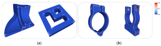
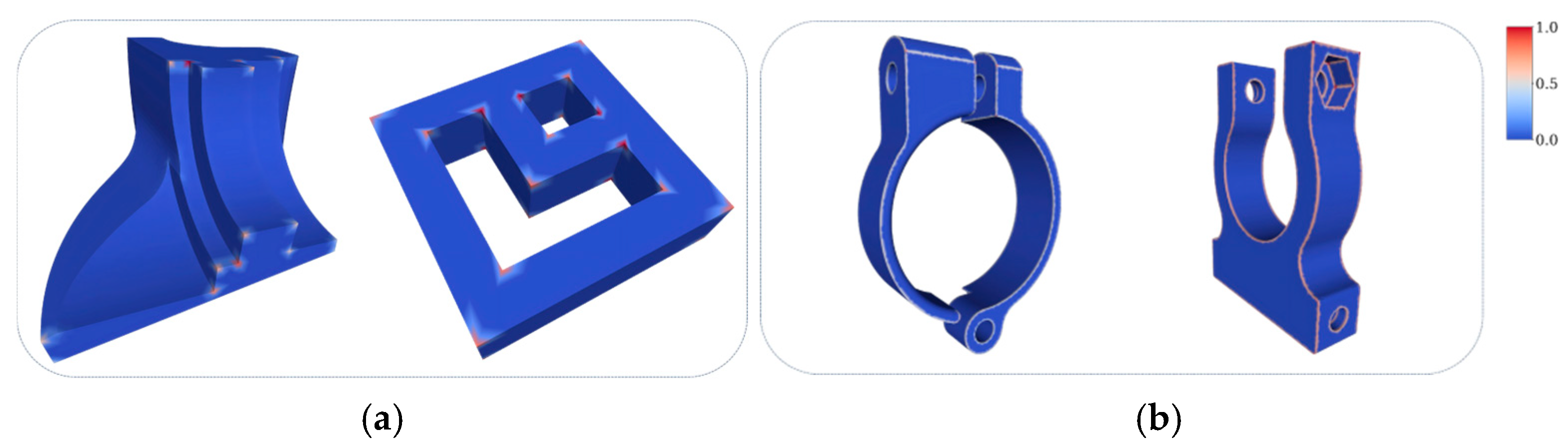
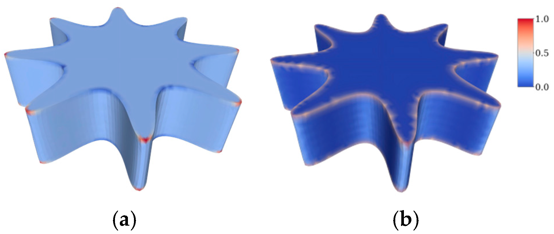
Importantly, Gaussian curvature provides only a necessary condition for developability and does not uniquely determine segmentation boundaries on discrete CAD meshes. This motivates the need for a segmentation formulation that is consistent with developability while remaining stable and observable in discrete settings. As illustrated in Figure 2, discrete Gaussian curvature exhibits diverse and often unstable spatial distributions on CAD models and does not consistently align with feature-aligned segmentation boundaries.
Figure 2.
Gaussian curvature distributions on different CAD models: (a) models where nonzero Gaussian curvature concentrates at isolated sharp corners; (b) models where nonzero Gaussian curvature forms extended bands near blends or boundary transitions.
3.1.2. Segmentation as Sparse Normal Discontinuity Detection
While Gaussian curvature characterizes intrinsic surface bending, segmentation boundaries in CAD models are primarily associated with extrinsic geometric discontinuities, namely abrupt changes in surface orientation.
Let denote the unit surface normal field. For piecewise developable CAD surfaces, the normal field exhibits a characteristic structure:
- Within each developable patch, surface normals vary smoothly and coherently under strong geometric constraints;
- Across patch boundaries, the normal field undergoes discrete jumps associated with sharp creases or feature edges.
As a consequence, segmentation should not be formulated as minimizing the magnitude of curvature or normal variation, but rather as identifying a sparse set of normal discontinuities in the surface normal field.
Formally, consider an ideal segmentation of the surface. For a piecewise developable model, significant changes in surface orientation occur only at patch boundaries. This observation motivates the following idealized formulation:
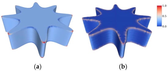
where denotes the pseudo-norm counting the number of nonzero entries. This formulation emphasizes that segmentation seeks to minimize the number of normal discontinuities, rather than the magnitude of normal variation. The support of therefore directly corresponds to the desired segmentation boundaries. Figure 3 illustrates this distinction on the same CAD model. While Gaussian curvature exhibits spurious and diffused responses even on theoretically developable regions, surface normal discontinuities consistently reveal feature-aligned segmentation boundaries.
Figure 3.
Comparison between Gaussian curvature and surface normal discontinuities on the same CAD model: (a) Gaussian curvature visualization, exhibiting unstable and spatially diffused responses on developable regions; (b) normal discontinuity visualization, consistently revealing feature-aligned segmentation boundaries.
3.1.3. Discrete Proxy via Sparse Normal Gradient
On a triangle mesh , surface normals are defined per face. Normal discontinuities occur across shared edges between adjacent faces. Let and be two adjacent faces with unit normals and . The dihedral angle between them is defined as
It is important to emphasize that, although dihedral angle thresholding is often used heuristically for sharp edge detection in practice, here, it arises as a discrete realization of the normal gradient objective introduced in Section 3.1.2. In our formulation, dihedral angles are not used as proxies for curvature. Instead, they serve as discrete indicators of normal jump discontinuities. A large dihedral angle implies a significant change in surface orientation, while a small angle corresponds to smooth normal variation within a developable patch.
Based on this interpretation, we approximate the sparse normal gradient objective by thresholding dihedral angles:
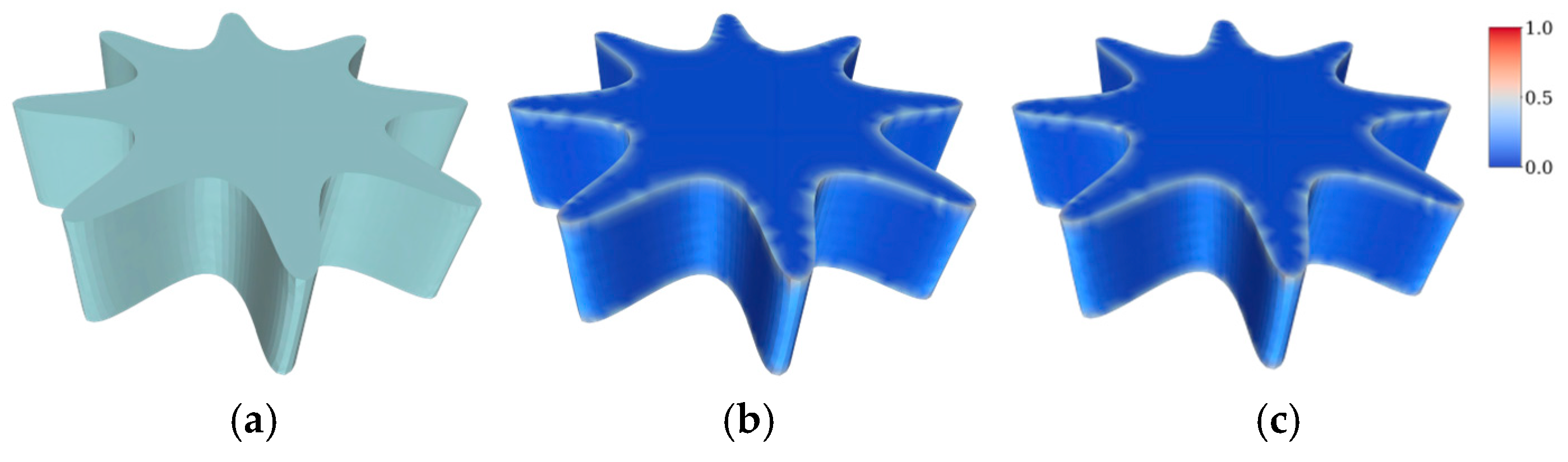
where denotes the indicator function, and is a user-specified threshold. This discrete formulation preserves the support of normal discontinuities rather than approximating their magnitude, thereby avoiding unstable curvature estimation. Moreover, it naturally induces a graph-based segmentation algorithm, as illustrated in Figure 4.
Figure 4.
Discrete realization of sparse normal discontinuities on a triangle mesh: (a) input CAD model; (b) conceptual visualization of continuous normal discontinuities for reference; (c) dihedral angle visualization serving as a discrete proxy for detecting normal jumps between adjacent faces.
3.2. Discrete Segmentation Algorithm
Based on the formulation derived in Section 3.1, we now describe a simple and efficient algorithm for developable surface segmentation on triangle meshes. The proposed algorithm provides a discrete solver for formulation (1) by identifying normal discontinuities through dihedral angle thresholding and extracting connected components accordingly. The overall pipeline consists of three main steps: face normal computation, boundary edge detection, and connected component segmentation.
3.2.1. Face Adjacency and Normal Computation
Let the input be a triangle mesh
where is the set of vertices, and is the set of triangular faces. We operate on a face-based representation, which is more robust than vertex-based quantities for CAD models with sharp features.
For each face , we compute its unit normal as
We further construct the face adjacency graph by identifying pairs of faces that share a common edge. This adjacency information is used both to evaluate normal variations across edges and to propagate segmentation labels in subsequent steps.
3.2.2. Boundary Detection via Dihedral Angle Thresholding
According to formulation (1), segmentation boundaries correspond to locations where normal jump discontinuities occur. On a triangle mesh, the normal gradient across a shared edge is naturally measured by the dihedral angle between the two adjacent faces.
For each pair of adjacent faces and , we compute the dihedral angle
An edge shared by and is classified as a boundary edge if
where is a user-specified threshold controlling the sparsity of normal gradients.
This hard-thresholding operation can be interpreted as a discrete realization of the formulation in (1): edges exhibiting significant normal jumps are treated as nonzero gradient locations, while edges with smooth normal transitions are suppressed. In practice, the threshold has a clear geometric interpretation and directly corresponds to the expected sharpness of creases in CAD models.
3.2.3. Connected Component Segmentation
After boundary detection, we construct a reduced face adjacency graph
where nodes correspond to faces, and an edge exists between two faces if and only if they are adjacent and their shared edge is not classified as a boundary.
We then extract the connected components of using standard graph traversal algorithms (e.g., breadth-first search). Each connected component represents a maximal region over which surface normals vary smoothly and is therefore identified as a candidate developable patch.
This step completes the discrete interpretation of formulation (1): minimizing the number of detected normal discontinuities partitions the mesh into piecewise smooth regions separated by sparse, feature-aligned boundaries.
3.2.4. Algorithm Summary and Complexity
The complete segmentation algorithm can be summarized as follows:
- Compute face normals and face adjacency.
- Detect boundary edges by thresholding dihedral angles.
- Extract connected components to obtain initial patches.
The algorithm runs in linear time with respect to the number of faces and edges. Since it relies solely on first-order geometric quantities, it is robust to mesh resolution and well-suited for large-scale CAD models.
3.3. Implementation Details
In this section, we provide implementation details that are essential for reproducibility and robustness, yet orthogonal to the core algorithmic formulation described in Section 3.2. These details clarify practical design choices when applying the proposed method to real-world CAD meshes.
3.3.1. Mesh Representation and Data Structures
The input CAD model is represented as a triangle mesh
where and denote the vertex and face sets, respectively. All geometric computations are performed at the face level, which is more appropriate for CAD models containing sharp geometric features.
The face adjacency information constructed in Section 3.2 is reused throughout the implementation. Each undirected mesh edge is associated with at most two incident faces. Edges incident to a single face (i.e., mesh boundary edges) are treated as segmentation boundaries by default.
3.3.2. Numerical Stability in Dihedral Angle Computation
Face normals are computed using the standard cross-product formulation and normalized to unit length. For each pair of adjacent faces, the dihedral angle is evaluated via the dot product of their normals.
To ensure numerical stability, the dot product is clamped to the interval before applying the arccosine operation. This step prevents invalid values caused by floating-point inaccuracies, which could otherwise propagate into erroneous boundary detection on nearly coplanar faces.
Since dihedral angles depend only on local face geometry, their computation is invariant to global mesh scale and robust under non-uniform tessellation, which is particularly important for CAD models.
3.3.3. Threshold Selection and Parameter Sensitivity
The dihedral angle threshold is the only user-defined parameter in our implementation. Unlike abstract optimization weights used in many segmentation methods, has a clear geometric interpretation: it represents the minimal crease angle considered significant for segmentation.
In practice, we observe that values of in the range of to produce consistent and interpretable results across a wide variety of CAD models. Smaller values tend to introduce over-segmentation by detecting shallow surface variations, while larger values yield coarser segmentations by suppressing mild creases.
Importantly, segmentation results are stable under small perturbations of . This behavior reflects the sparsity-driven nature of formulation (1), in which the solution structure changes only when the threshold crosses geometrically meaningful normal discontinuities.
3.3.4. Complexity and Practical Performance
Both time and memory complexity scale linearly with respect to the number of faces. The algorithm does not require iterative solvers, matrix factorizations, or numerical optimization libraries. This simplicity facilitates integration into existing CAD processing pipelines and enables efficient processing of large-scale industrial models.
4. Experimental Results
In this section, we evaluate the proposed developable surface segmentation method on a variety of CAD models. Our experiments are designed to assess three key aspects: (1) boundary accuracy on piecewise developable surfaces, (2) robustness with respect to mesh resolution and parameter variation, and (3) computational efficiency compared to existing approaches. Our method was implemented in Python 3.14.2 and on a mobile workstation with an Intel Core Ultra 5 125H and 32GB of memory. Table 1 summarizes the statistics of our results.
Table 1.
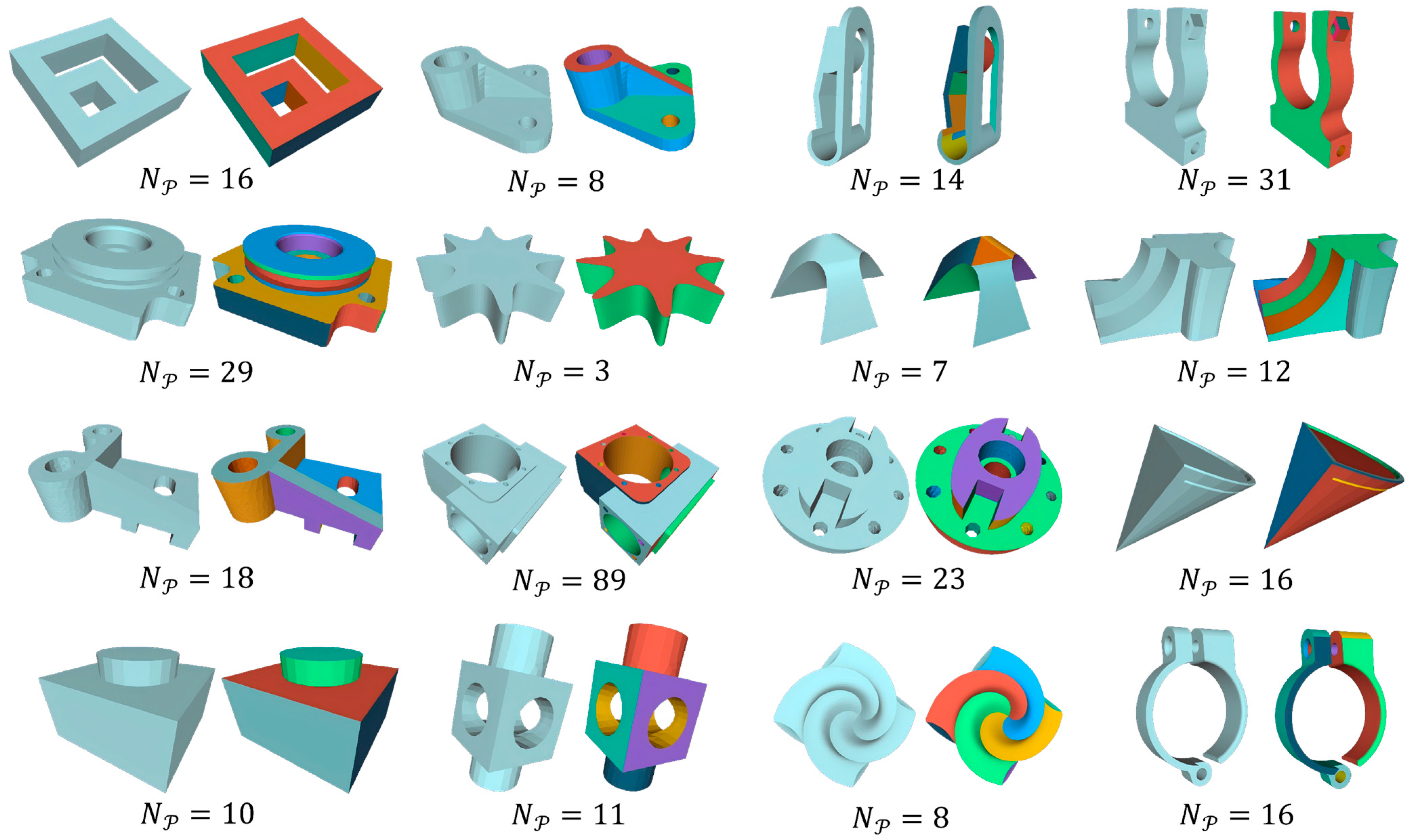
Statistical results. We report the number of vertices , faces , segmented patches , maximum discrete Gaussian curvature , and the total processing time in seconds. The “Models” column refers to the (row, column) indices of the examples shown in Figure 5.
4.1. Experimental Setup
We evaluate the proposed developable surface segmentation method on a diverse collection of CAD models commonly used in geometric processing and reverse engineering, including mechanical parts, architectural components, and synthetic models with known developable structures. These models contain a mixture of planar, cylindrical, and conical surfaces separated by sharp creases.
All input models are represented as triangle meshes with varying resolutions, ranging from several thousand to several hundred thousand faces. No preprocessing, such as remeshing, smoothing, or curvature estimation, is applied prior to segmentation. To quantify the geometric complexity and potential noise level of each model, we compute the discrete Gaussian curvature at each vertex using the angle deficit method [7]. We report the maximum absolute curvature in Table 1. Unless otherwise specified, the dihedral angle threshold is fixed across experiments.
4.2. Qualitative Segmentation Results
Figure 5 shows representative segmentation results produced by the proposed method, where each developable patch is visualized with a distinct color.
As illustrated, segmentation boundaries align closely with sharp creases and design features present in the original CAD models. Large planar and cylindrical regions are correctly grouped into single patches, while transitions between different developable regions are clearly delineated.
This visual coherence, confirmed by the consistently low maximum discrete Gaussian curvature () reported in Table 1, directly validates the accuracy of our method in recovering developable surfaces. Furthermore, the clean delineation of boundaries across diverse models demonstrates the method’s robustness to varying geometric complexities, a key objective of our sparsity-driven formulation.
In contrast to curvature-based methods, no spurious boundaries appear within smooth regions, even on meshes with irregular tessellation. This behavior confirms that the sparse normal discontinuity prior effectively suppresses numerical noise while preserving geometrically meaningful discontinuities.
Figure 5.
Developable segmentation results on multiple CAD models. : the number of segmented patches.
4.3. Comparison with the Existing Method
We compare our method with Zeng et al. [9], which is the most relevant prior work on developable surface segmentation for CAD models. Existing mesh segmentation approaches are mostly designed for general-purpose decomposition or curvature-driven analysis, whereas Zeng et al. explicitly target developable surface segmentation on CAD meshes. Therefore, the comparison focuses on this representative method.
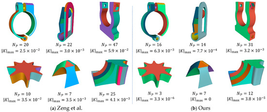
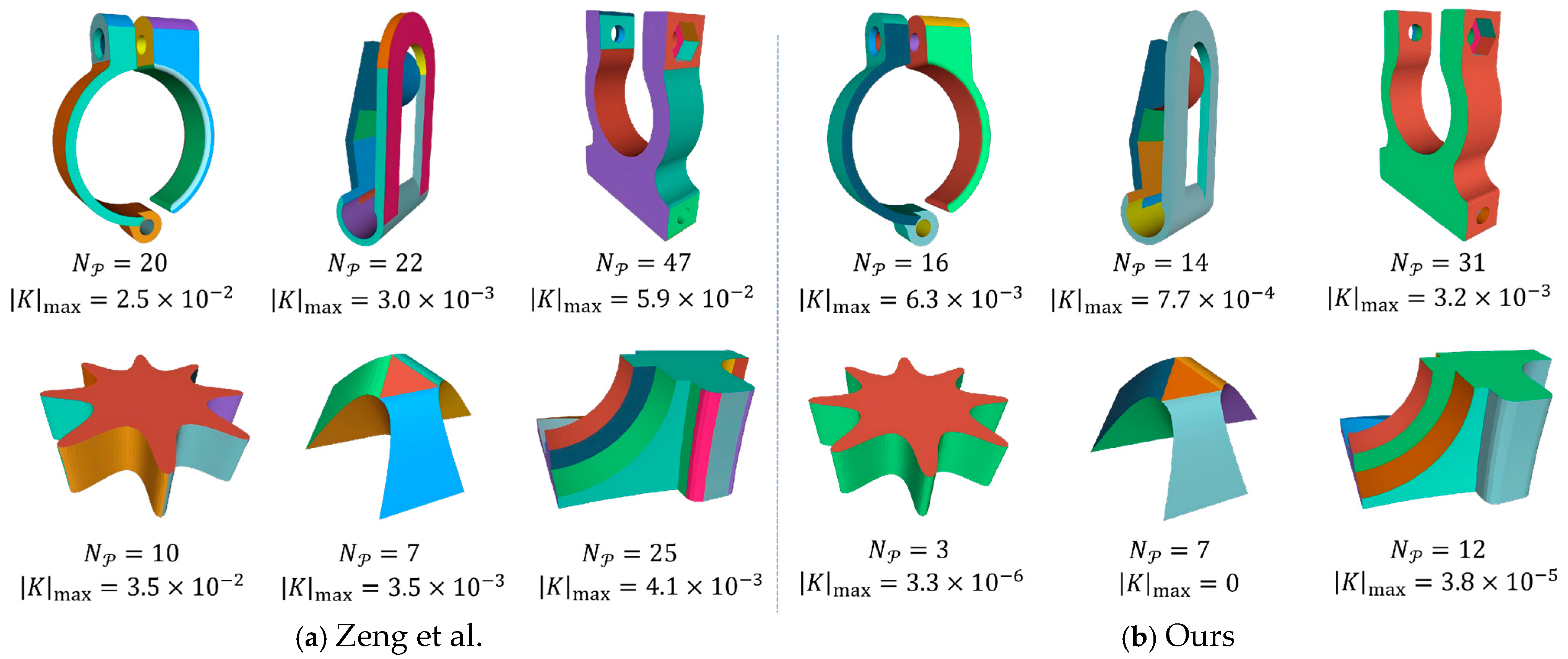
Figure 6 shows qualitative comparisons on the same input models, with the number of segmented patches () and the maximum absolute Gaussian curvature () reported for each result. As shown, the method of Zeng et al. [9] generally produces a larger , especially near sharp creases and transition regions, indicating a clear tendency toward over-segmentation. Crucially, this over-segmentation is accompanied by significantly higher values, suggesting that their curvature-based clustering is sensitive to local numerical noise and deviates from the theoretical developability condition (). In contrast, our method yields fewer and more coherent patches while consistently achieving much lower values. This dual advantage—reduced over-segmentation and superior metrics—provides objective proof that our approach effectively balances boundary adherence with the recovery of large-scale developable primitives with higher geometric fidelity.
Figure 6.
Comparisons with Zeng et al. [9] on CAD models. The proposed method produces fewer patches while preserving feature-aligned boundaries, indicating reduced over-segmentation near sharp creases.
This difference arises from the underlying formulation. Zeng et al. rely on Gauss map analysis and region growing based on normal distribution statistics, which can be sensitive to local normal variations and parameter settings on CAD meshes. While sharp features often disrupt curvature-based statistics in region-growing methods, our approach directly detects sparse normal discontinuities via dihedral angles, avoiding iterative region growing and higher-order statistical tests. As a result, large planar and cylindrical regions are more consistently grouped into single developable patches.
Overall, the comparison demonstrates that exploiting the sparsity of surface normal discontinuities provides a simpler solution that is robust in practice for CAD-style developable surface segmentation.
4.4. Parameter Sensitivity
The proposed method involves only a single user-defined parameter: the dihedral angle threshold . This parameter has a clear geometric interpretation, as it defines the minimum change in surface orientation considered significant for segmentation. Compared with optimization-based methods that require multiple abstract weights, this simplicity greatly simplifies practical parameter selection.
The effect of varying τ within the range of to is illustrated in Figure 5. In practice, when is chosen within this interval, most CAD models do not require further parameter tuning, which demonstrates the robustness and ease of use of the proposed method.
The effect of can be understood through two representative geometric regimes commonly observed in CAD models. For models composed of planar or cylindrical patches with strong and well-separated creases, segmentation remains stable across a wide range of values, as normal discontinuities at patch boundaries are pronounced. In contrast, models containing subtle yet meaningful creases or smoothly varying surface orientation require slightly smaller or larger values to balance the detection of weak but relevant discontinuities against over-segmentation caused by gradual normal variation.
Across all the tested models, segmentation changes occur only when crosses geometrically meaningful thresholds, rather than varying continuously with the parameter. This behavior reflects the sparsity-driven nature of the formulation, where segmentation boundaries correspond to a small number of significant normal discontinuities, resulting in stable solutions under moderate parameter perturbations.
4.5. Computational Efficiency
The proposed algorithm consists exclusively of local geometric computations and graph traversal operations. Consequently, its time complexity is strictly linear with respect to the number of mesh faces .
As summarized in Table 1, the processing time scales linearly with mesh size. For example, the smallest model (2, 4) with 13k faces is processed in 0.43 s, while the largest tested model (3, 2) with 64k faces takes 2.24 s. This consistent linear relationship confirms the theoretical complexity analysis.
This performance reflects the non-iterative nature of the algorithm and its reliance on simple, local operations. The absence of iterative solvers or global optimization procedures further simplifies the implementation and makes the proposed method well-suited for large-scale industrial CAD datasets where linear complexity is critical for interactive performance.
5. Discussion
The experimental results further validate the effectiveness of the proposed method on CAD models. By focusing on first-order geometric discontinuities rather than unstable discrete curvature estimates, the method achieves accurate, robust, and efficient segmentation.
While simple dihedral angle thresholding is often used as a heuristic in CAD preprocessing, our work formalizes it as the solution to a sparse normal gradient minimization problem. This theoretical grounding explains why it works and provides a basis for robust implementation. By incorporating connectivity analysis into sparse support detection, our formulation avoids the “dust” and manual cleanup often required by ad hoc thresholding, ensuring topologically valid segmentation across varying models using a unified parameter strategy.
In certain cases, linear creases separating geometrically similar planar or developable regions may still be detected as segmentation boundaries, as they correspond to abrupt changes in surface orientation. This behavior is consistent with the sparsity-driven formulation, which explicitly prioritizes first-order normal discontinuities. Resolving such cases would require higher-level geometric or semantic reasoning, which lies beyond the scope of the current model.
Although the proposed method is primarily designed for piecewise developable surfaces, it also performs well on models containing a mixture of developable and mildly curved regions. In such cases, the resulting segmentations remain intuitive and continue to respect sharp geometric features.
6. Conclusions
In this paper, we presented a simple yet robust method for segmenting CAD models into developable surface patches based on a sparse normal discontinuity prior. By reinterpreting developable surface segmentation as the detection of sparse geometric discontinuities in surface orientation, we decoupled the notion of developability from unstable discrete curvature estimation and formulated segmentation directly in terms of observable normal jumps.
Starting from an idealized formulation that minimizes the support of surface orientation discontinuities, we showed that, on triangle meshes, this objective admits a simple and robust first-order realization based on dihedral angles. This formulation avoids the numerical instability inherent in discrete curvature estimation and leads to a tractable, linear-time segmentation algorithm. Unlike optimization-heavy approaches, the proposed method relies on a single geometrically interpretable parameter and naturally aligns segmentation boundaries with sharp features commonly found in CAD models.
Experimental results on a variety of mechanical and architectural CAD models demonstrate that the proposed approach produces clean and consistent segmentation boundaries, remains robust under variations in mesh resolution and parameter values, and achieves high computational efficiency. These properties make the method particularly suitable for practical CAD processing and reverse engineering pipelines, where robustness and scalability are essential. Furthermore, the clean segmentation of feature lines and surface patches serves as a robust preprocessing step for downstream engineering tasks, such as boundary condition assignment in CFD and feature-preserving meshing for FEA.
The main limitation of the proposed approach lies in its reliance on sharp normal discontinuities. While this assumption is well justified for piecewise developable CAD models, it may be less effective for organically shaped surfaces characterized by smoothly varying surface orientation. Extending the sparse discontinuity formulation to handle hybrid models containing both developable and smoothly curved regions constitutes an interesting direction for future work.
Overall, this work demonstrates that a sparsity-driven, first-order geometric perspective provides a principled and practical foundation for developable surface segmentation. We believe that this formulation not only offers an effective solution for CAD models but also opens new possibilities for applying sparse geometric priors to other segmentation and decomposition problems in geometry processing.
Author Contributions
Conceptualization, L.X.; methodology, L.X., H.G. and S.D.; validation, L.X., H.G. and F.W.; investigation, L.X. and Q.Z.; data curation, F.W. and Q.Z.; writing—original draft preparation, L.X.; writing—review and editing, L.X. and S.D.; visualization, H.G., F.W. and Q.Z.; funding acquisition, L.X. All authors have read and agreed to the published version of the manuscript.
Funding
This research was funded by the Special Fund for the Local Science and Technology Development of the Central Government (Grant No. 2022ZY0172), the Natural Science Foundation of Inner Mongolia (Grant No. 2023LHMS06018), the National Natural Science Foundation of China Regional Science Fund Project (Grant No. 12265020), the Inner Mongolia Autonomous Region Higher Education Institutions Young Scientific and Technological Talent Support Project (Grant No. NJYT24066), and the Inner Mongolia Autonomous Region Natural Science Foundation General Program (Grant No. 2025MS01024).
Data Availability Statement
The original contributions presented in this study are included in the article. The test models used to support the findings are available from the corresponding author upon request. The source code is not publicly available due to intellectual property restrictions and its use in ongoing research.
Conflicts of Interest
The authors declare no conflicts of interest.
References
- Pottmann, H.; Asperl, A.; Hofer, M.; Kilian, A. Architectural Geometry; Bentley Institute Press: Exton, PA, USA, 2007. [Google Scholar]
- Wang, C.C.L.; Tang, K. Optimal Boundary Triangulations of an Interpolating Ruled Surface. J. Comput. Inf. Sci. Eng. 2005, 5, 291–301. [Google Scholar] [CrossRef] [Scilit]
- Bo, P.; Wang, W. Geodesic-Controlled Developable Surfaces for Modeling Paper Bending. Comput. Graph. Forum 2007, 26, 365–374. [Google Scholar] [CrossRef] [Scilit]
- Pottmann, H.; Wallner, J. Approximation Algorithms for Developable Surfaces. Comput. Aided Geom. Des. 1999, 16, 539–556. [Google Scholar] [CrossRef] [Scilit]
- Várady, T.; Martin, R.R.; Cox, J. Reverse Engineering of Geometric Models—An Introduction. Comput.-Aided Des. 1997, 29, 255–268. [Google Scholar] [CrossRef] [Scilit]
- Benkő, P.; Martin, R.R.; Várady, T. Algorithms for Reverse Engineering Boundary Representation Models. Comput.-Aided Des. 2001, 33, 839–851. [Google Scholar] [CrossRef] [Scilit]
- Meyer, M.; Desbrun, M.; Schröder, P.; Barr, A.H. Discrete Differential-Geometry Operators for Triangulated 2-Manifolds. In Visualization and Mathematics III, 1st ed.; Hege, H.C., Polthier, K., Eds.; Springer: Berlin/Heidelberg, Germany, 2003; pp. 35–57. [Google Scholar]
- Rusinkiewicz, S. Estimating Curvatures and Their Derivatives on Triangle Meshes. In Proceedings of the 2nd International Symposium on 3D Data Processing, Visualization and Transmission, Thessaloniki, Greece, 6–9 September 2004; pp. 486–493. [Google Scholar]
- Zeng, Z.; Jia, X.; Shen, L.; Bo, P. Developable Surface Segmentation for CAD Models. In SIGGRAPH ’21 Posters; Association for Computing Machinery: New York, NY, USA, 2021; pp. 1–2. [Google Scholar]
- Julius, D.; Kraevoy, V.; Sheffer, A. D-Charts: Quasi-developable mesh segmentation. Comput. Graph. Forum 2005, 24, 581–590. [Google Scholar] [CrossRef] [Scilit]
- Lévy, B.; Petitjean, S.; Ray, N.; Maillot, J. Least squares conformal maps for automatic texture atlas generation. In Seminal Graphics Papers: Pushing the Boundaries, 1st ed.; ACM: New York, NY, USA, 2023; Volume 2, pp. 193–202. [Google Scholar]
- Hormann, K.; Greiner, G. MIPS: An efficient global parameterization method. In Curve and Surface Design: Saint-Malo; Vanderbilt University Press: Nashville, TN, USA, 2000; pp. 153–162. [Google Scholar]
- Alliez, P.; Cohen-Steiner, D.; Devillers, O.; Lévy, B.; Desbrun, M. Anisotropic polygonal remeshing. In ACM SIGGRAPH 2003 Papers, 1st ed.; ACM: San Diego, CA, USA, 2003; pp. 485–493. [Google Scholar]
- Taubin, G. Estimating the Tensor of Curvature of a Surface from a Polyhedral Approximation. In Proceedings of the IEEE International Conference on Computer Vision, Boston, MA, USA, 20–23 June 1995; pp. 902–907. [Google Scholar]
- Cohen-Steiner, D.; Morvan, J.-M. Restricted Delaunay Triangulations and Normal Cycle. In Proceedings of the 19th Annual Symposium on Computational Geometry, San Diego, CA, USA, 8–10 June 2003; pp. 312–321. [Google Scholar]
- Liu, Y.; Wang, W.; Lévy, B.; Sun, F.; Yan, D.; Lu, L.; Yang, C. On Centroidal Voronoi Tessellation—Energy Smoothness and Fast Computation. ACM Trans. Graph. 2009, 28, 101. [Google Scholar] [CrossRef] [Scilit]
- Zhang, Y.; Zheng, J. An Overview of Developable Surfaces in Geometric Modeling. Recent Pat. Eng. 2022, 16, 87–103. [Google Scholar]
- Donoho, D.L. Compressed Sensing. IEEE Trans. Inf. Theory 2006, 52, 1289–1306. [Google Scholar] [CrossRef] [Scilit]
- Candès, E.J.; Recht, B. Exact matrix completion via convex optimization. Found. Comput. Math. 2009, 9, 717–772. [Google Scholar] [CrossRef] [Scilit]
- Elad, M. Sparse and Redundant Representations: From Theory to Applications in Signal and Image Processing; Springer Science & Business Media: New York, NY, USA, 2010. [Google Scholar]
- Wang, R.; Yang, Z.; Liu, L.; Deng, J.; Chen, F. Decoupling Noise and Features via Weighted ℓ1-Analysis Compressed Sensing. ACM Trans. Graph. 2014, 33, 1–12. [Google Scholar]
- Rudin, L.I.; Osher, S.; Fatemi, E. Nonlinear Total Variation Based Noise Removal Algorithms. Phys. D 1992, 60, 259–268. [Google Scholar] [CrossRef] [Scilit]
- Xu, L.; Lu, C.; Xu, Y.; Jia, J. Image smoothing via ℓ0 gradient minimization. In Proceedings of the 2011 SIGGRAPH Asia Conference, Hong Kong, China, 12–15 December 2011; pp. 1–12. [Google Scholar]
- He, L.; Schaefer, S. Mesh denoising via ℓ0 minimization. ACM Trans. Graph. 2013, 32, 64. [Google Scholar] [CrossRef] [Scilit]
- Avron, H.; Sharf, A.; Greif, C.; Cohen-Or, D. ℓ1-sparse reconstruction of sharp point set surfaces. ACM Trans. Graph. 2010, 29, 135. [Google Scholar] [CrossRef] [Scilit]
- Xu, L.; Wang, R.; Zhang, J.; Yang, Z.; Deng, J.; Chen, F.; Liu, L. Survey on Sparsity in Geometric Modeling and Processing. Graph. Models 2015, 82, 160–180. [Google Scholar] [CrossRef] [Scilit]
- Sapidis, N.S.; Besl, P.J. Direct Construction of Polynomial Surfaces from Dense Range Images through Region Growing. ACM Trans. Graph. 1995, 14, 171–200. [Google Scholar] [CrossRef] [Scilit]
- Han, J.H.; Requicha, A.A.G. Feature Recognition from CAD Models. IEEE Comput. Graph. Appl. 2002, 18, 80–94. [Google Scholar]
- Attene, M.; Falcidieno, B.; Spagnuolo, M. Hierarchical Mesh Segmentation Based on Fitting Primitives. Vis. Comput. 2006, 22, 181–193. [Google Scholar] [CrossRef] [Scilit]
- Cohen-Steiner, D.; Alliez, P.; Desbrun, M. Variational shape approximation. In ACM SIGGRAPH 2004 Papers, 1st ed.; ACM: Los Angeles, CA, USA, 2004; pp. 905–914. [Google Scholar]
- Ohtake, Y.; Belyaev, A.; Seidel, H.P. Ridge-Valley Lines on Meshes via Implicit Surface Fitting. In ACM SIGGRAPH 2004 Papers, 1st ed.; ACM: Los Angeles, CA, USA, 2004; pp. 609–612. [Google Scholar]
- Kim, H.S.; Choi, H.K.; Lee, K.H. Feature Detection of Triangular Meshes Based on Tensor Voting Theory. Comput.-Aided Des. 2009, 41, 47–58. [Google Scholar] [CrossRef] [Scilit]
- Fleishman, S.; Drori, I.; Cohen-Or, D. Bilateral mesh denoising. In ACM SIGGRAPH 2003 Papers, 1st ed.; ACM: San Diego, CA, USA, 2003; pp. 950–953. [Google Scholar]
- Lee, K.W.; Wang, W.P. Feature-Preserving Mesh Denoising via Bilateral Normal Filtering. In Proceedings of the Ninth International Conference on Computer Aided Design and Computer Graphics, Hong Kong, China, 7–10 December 2005; pp. 1–6. [Google Scholar]
- Pauly, M.; Keiser, R.; Gross, M. Multi-Scale Feature Extraction on Point-Sampled Surfaces. Comput. Graph. Forum 2003, 22, 281–289. [Google Scholar] [CrossRef] [Scilit]
- Sun, J.; Ovsjanikov, M.; Guibas, L. A Concise and Provably Informative Multi-Scale Signature Based on Heat Diffusion. Comput. Graph. Forum 2009, 28, 1383–1392. [Google Scholar] [CrossRef] [Scilit]
- Shlafman, S.; Tal, A.; Katz, S. Metamorphosis of Polyhedral Surfaces Using Decomposition. Comput. Graph. Forum 2002, 21, 219–228. [Google Scholar] [CrossRef] [Scilit]



Disclaimer/Publisher’s Note: The statements, opinions and data contained in all publications are solely those of the individual author(s) and contributor(s) and not of MDPI and/or the editor(s). MDPI and/or the editor(s) disclaim responsibility for any injury to people or property resulting from any ideas, methods, instructions or products referred to in the content. |
© 2026 by the authors. Licensee MDPI, Basel, Switzerland. This article is an open access article distributed under the terms and conditions of the Creative Commons Attribution (CC BY) license.