


Abstract
This study examines the translational motion of a compound droplet consisting of concentric viscous fluid layers as it moves through a bounded micropolar fluid under the influence of interfacial phenomena. The inner core and surrounding shell form a symmetric two-interface configuration, analyzed in the low-Reynolds-number regime. The governing equations are solved analytically, incorporating interfacial boundary conditions that enforce continuity of flow flux and hydrodynamic stresses across both droplet surfaces. The expressions are obtained for the velocity field, vorticity, and microrotation, expressed in terms of shell thickness, micropolarity parameters, spin characteristics, and the effective viscosity ratio. The resulting hydrodynamic force behavior is shown to be highly sensitive to these parameters. Overall, this work establishes a theoretical framework for axisymmetric motion of core–shell droplets and offers valuable insights for the design of tunable microcapsules, advanced drug-delivery vehicles, and biomimetic encapsulated systems in microfluidic applications.
MSC:
74F10
1. Introduction
Understanding the behavior of spherical particles in viscous fluids is fundamental to many areas of fluid mechanics, chemical engineering, and colloid science. A viscous fluid, characterized by internal friction that resists deformation, governs particle motion primarily through viscous rather than inertial forces under low-Reynolds-number conditions. The classical description of this regime originates from the pioneering work of Stokes [1], who established the drag force acting on a sphere moving slowly through a viscous medium. This foundational theory was later expanded and formalized by Happel and Brenner [2], whose comprehensive treatment of creeping-flow hydrodynamics introduced resistance and mobility functions that describe both isolated spheres and hydrodynamically interacting particles. Their framework remains central to modern analyses of sedimentation, colloidal suspensions, and particle-based rheological measurements, and continues to be extended in the contemporary microhydrodynamics literature such as that of Kim and Karrila [3].
Micropolar fluid theory provides a generalized continuum framework capable of describing fluids whose microstructure significantly influences their macroscopic behavior. Unlike classical Newtonian fluids, micropolar fluids incorporate the effects of particle rotation, microrotation inertia, and couple stresses, allowing the model to capture the dynamics of suspensions containing rigid or deformable microelements such as polymers, colloids, or biological fluids. The foundational formulation introduced by Eringen [4] establishes balance laws for both linear and angular momentum, leading to additional field variables such as microrotation vectors and asymmetric stress tensors. This enriched description enables the prediction of phenomena that classical fluid theory cannot account for, including size-dependent viscosity, rotational boundary layers, and enhanced shear resistance. Eringen’s later development of microcontinuum field theories [5] further extends the framework, providing a unified theoretical basis for modeling complex media with internal structure, including micropolar, microstretch, and micromorphic fluids. These models continue to play a central role in modern studies of non-Newtonian flows, porous media transport, and micro-scale fluid mechanics.
Compound or composite spheres—structures consisting of two or more concentric layers with distinct material properties—play a significant role in understanding multiphase transport phenomena, interfacial mechanics, and microhydrodynamic interactions. Their behavior differs fundamentally from that of homogeneous particles because internal interfaces introduce additional degrees of freedom such as interfacial tension gradients, viscosity contrasts, and thermal discontinuities. These effects become especially important when compound droplets or layered particles move in confined geometries or near solid boundaries, where the interplay between hydrodynamic stresses and interfacial forces governs their translational and rotational dynamics [6]. Recent studies have demonstrated that thermal gradients can couple with interfacial properties to significantly alter the motion of compound droplets near planar surfaces, leading to modified migration velocities and asymmetric deformation patterns [7]. Investigations of composite spherical particles moving between microstructured and viscous fluids show that interfacial dynamics play a major role in determining particle mobility, lubrication forces, and the stability of the surrounding fluid layers [8]. These results make it clear that compound spheres cannot be approximated as simple rigid bodies; their internal layering and interfacial behavior must be included to accurately describe their motion in microfluidic devices, multiphase suspensions, and material-processing flows. In practical applications such as coating processes, targeted transport, and the design of functional colloids, interactions with microstructured boundaries further influence near-wall stability and hydrodynamic response. Overall, the performance and transport characteristics of compound spheres are governed by the combined effects of internal structure, interfacial mechanics, and the local flow environment.
Several investigations have examined the motion of particles and droplets in microstructured fluids, providing a foundation for the present analysis. Sherief, Faltas, and El-Sapa [9] derived a general expression for the drag on a solid body of revolution moving at low Reynolds numbers in a microstretch fluid, establishing a baseline for resistance in continua with microstructural degrees of freedom. El-Sapa [10] extended this framework by analyzing the influence of an external magnetic field on a microstretch fluid drop embedded in another microstretch medium, demonstrating the strong coupling between magnetization and microstretch kinematics. The slow motion of a slightly deformed spherical droplet in a microstretch fluid was further explored by Sherief, Faltas, and El-Sapa [11], where shape perturbations were shown to significantly modify the internal flow and drag characteristics. In a related micropolar context, El-Sapa [12] investigated the settling slip velocity of a spherical particle in an unbounded micropolar fluid, revealing the essential role of microrotation in altering hydrodynamic resistance. These studies collectively highlight the importance of microstructural effects in determining drag, deformation, and flow behavior. The present work advances this line of research by considering a three-region compound droplet in a micropolar fluid and systematically quantifying the influence of viscosity ratios, spin, and micropolarity on velocities, vorticity, microrotation, and drag forces. Recent studies have explored droplet dynamics in complex flow environments, including the experimental characterization of droplet transport through asymmetric bifurcating microchannels [13], and the influence of droplet size on fluctuation velocities in homogeneous isotropic turbulence using VoF simulations [14]. Broader advances in droplet microfluidics have also highlighted emerging biomedical applications, where precise microscale flow control governs droplet formation, manipulation, and stability [15]. A fully non-linear analytical solution describes the flow generated by a spinning spheroid immersed in a rotating, stratified fluid [16].
Recent investigations into fluid dynamics have heavily focused on the behavior of colloidal particles and droplets under complex rheological conditions, highlighting the transient response of hydrophobic particles [17,18] and the rotational oscillations of particle pairs in micropolar fluids under slip conditions [19]. Further developments explore thermal and interfacial transport, including coupled thermophoretic and thermocapillary effects near immiscible fluid interfaces [20] as well as thermophoresis in Brinkman media [21]. Additional work addresses boundary and porous media effects, detailing the thermocapillary motion of fluid droplets [22] and the transient dynamics of rotating slippery particles inside spherical cavities [23]. Micro-hydrodynamic studies have also examined the creeping movement of soft colloidal particles near planar interfaces [24] and axisymmetric Stokes flow past spherical droplets or slip particles near circular disks [25]. At the broader scale, fundamental transport phenomena such as the thermocapillary migration of bubbles and drops [26], the time-dependent recovery of cells after large deformations [27], and cell-like droplet deformation models [28] provide crucial insights. Advanced thermal and external field configurations involve drop migration across temperature gradients [29], dielectrophoretic migration in uniform electric fields [30], and the hindered mobility of particles near soft interfaces [31]. Applications extending to droplet microfluidics [32] are complemented by theoretical formulations of arbitrary Stokes flow past fluid-coated spheres [33] and surfactant-laden droplet migration in non-isothermal flows [34]. Finally, modern perspectives on compound drops [35], self-propelled compound droplet dynamics [36], and thermocapillary migration within spherical cavities [37] complete the comprehensive framework for advanced microfluidic and rheological systems.
The analytical formulation developed in this work not only captures the complete micropolar behavior of the compound droplet but also reduces consistently to several important limiting configurations. When the micropolarity parameter , the system reverts to the classical Newtonian two-phase Stokes flow, eliminating microrotation and recovering symmetric vorticity fields. Setting suppresses micropolar viscosity in the outer region, yielding a purely viscous annulus and restoring the standard compound droplet model without microstructural effects. Likewise, the limit decouples the viscous shell from the core, reproducing the behavior of a single-phase micropolar droplet. When the spin parameter , intrinsic angular momentum vanishes and the microrotation field collapses to its classical no-spin form. In the geometric limit , the shell reduces to a single interface, recovering the velocity and drag characteristics of a micropolar droplet without an intermediate layer. These limiting cases demonstrate that the present formulation is fully compatible with established Newtonian and micropolar theories, while providing a unified and generalized framework capable of describing the coupled effects of viscosity ratios, microrotation, and interfacial dynamics in three-region compound droplet systems. There exist many applications [17], such as this flow-control mechanism utilizing bionic shark scales, that can be directly integrated into the design of bluff civil infrastructure—such as tall buildings, bridge pylons, and offshore structural columns with square or rectangular cross-sections—to mitigate severe aerodynamic drag, suppress flow separation, and minimize vortex-induced vibrations under adverse or oblique wind angles of attack.
2. Mathematical Modeling of Micropolar Fluid
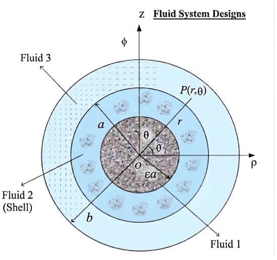
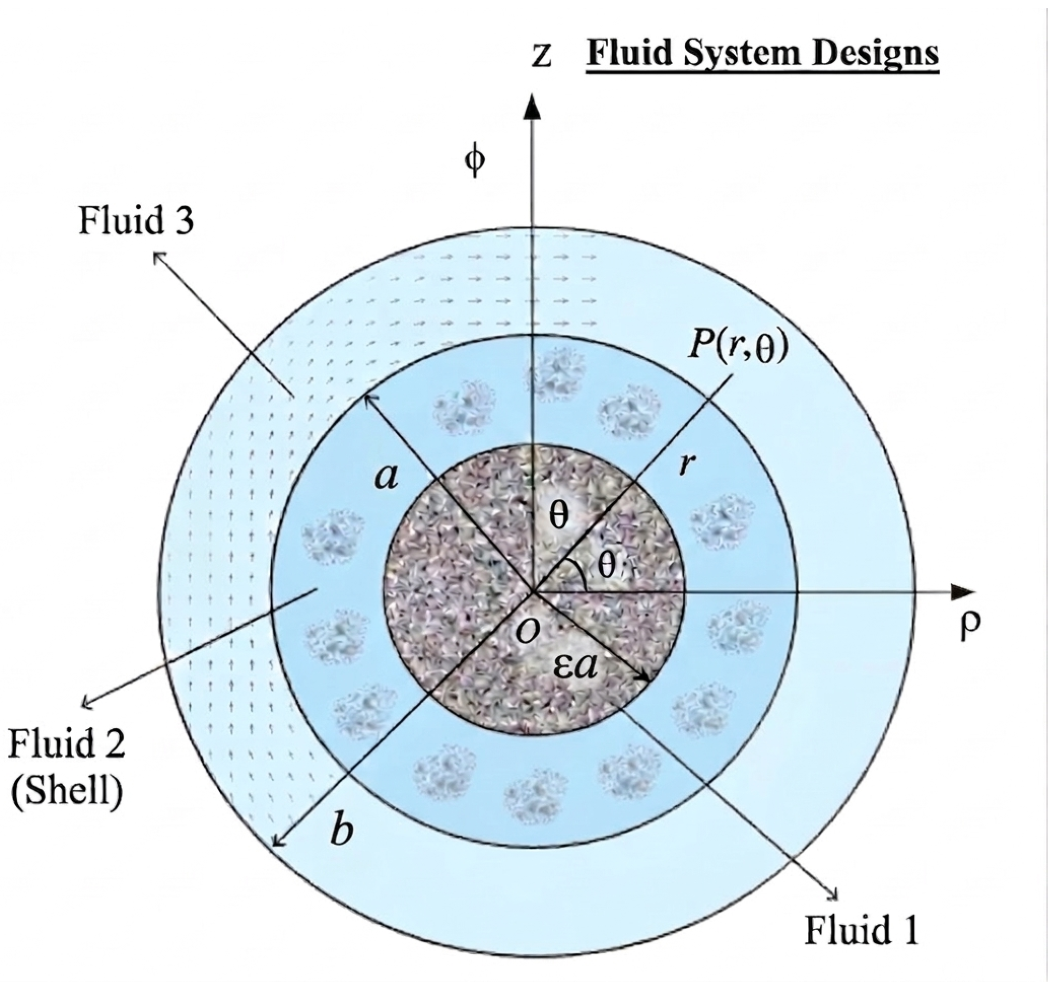
In this section, we formulate the hydrodynamic problem for each fluid phase. The steady and incompressible fluid motion is governed by the Navier–Stokes equations in Regions 1 and 2 by Happel and Brenner [2] in the absence of body forces. As shown in Figure 1, we adopt spherical coordinates with the origin located at the common center of the particle and the inner and outer shells. Additionally, the omission of interfacial tension and explicitly stating the validity regime (e.g., high capillary number conditions or systems where viscous and micropolar stresses dominate over capillary pressure jumps).
Figure 1.
Schematic of the multi-region fluid domain illustrating the hydrodynamic behavior of a compound droplet composed of viscous and micropolar fluid layers under the influence of interfacial effects.
The governing equations can be written as follows:
where , , and , , denote the velocity of the fluid particles, the pressure, and the viscosity of the viscous fluid in the two regions , respectively. By eliminating the pressure terms from the governing Equations (1) and (2) and substituting the above representation into the resulting system, we derive a set of quasi-steady, fourth-order differential equations in stream function :
where
The solution of Equation (3) is
where is an infinitesimal parameter, . All field functions, the velocity components, stresses, and vorticity , respectively, at are
All field functions in are
In Region 3 (), covered by micropolar fluid by Eringen [4,5] in the low Reynolds number regime, the absence of body forces is given by
where , and p are the velocity vector, the microrotation, and the fluid pressure at any point. The material constants are the viscosity coefficients of the classical viscous fluid, and and are the new viscosity coefficients for micropolar fluids. Let denote a spherical polar coordinates system. We may choose the vectors and in the form
The system of equations under consideration reduces to the following linear partial differential equations for the stream functions:
where , , is the micropolar parameter and . The solutions of Equation (18), the velocity components, microrotation, and stresses can be written in terms of the stream function as
where are the modified Bessel functions of the first kind and are the second kind. The boundary conditions are as follows: At the inner core of the compound droplet :
At the interface of the compound droplet :
where s is the spin parameter. The adopted spin boundary condition is considered a phenomenological representation of the rotational coupling between the microrotation and the macroscopic fluid vorticity. The dimensionless spin parameter characterizes the strength of this coupling. Since direct experimental measurements of interfacial microrotation in compound droplets are currently limited, the parameter is treated as an effective model parameter. Experimental determination or calibration of this parameter for specific biological or colloidal fluids represents an important direction for future research. Since the inner and outer components constitute a rigid compound droplet, they undergo the same translational motion. Hence, the translational velocities appearing at the respective interfaces are not independent and satisfy , where U denotes the translational velocity of the compound droplet.
At the surface of the cavity :
The outer boundary at represents a rigid, stationary spherical cavity wall, to which the no-slip boundary condition is imposed; therefore, no Happel or Kuwabara cell-model boundary condition is employed in the present formulation. The axial drag forces acting on viscous and micropolar compound are given by
Inserting (6)–(12) and (21)–(24) into the boundary conditions (25)–(34), we obtain the twelve equations in twelve unknowns:
We can determine the unknown integration constants () arising from the general solutions of the velocity, pressure, and microrotation fields across the three concentric domains: at the inner core–shell interface (), at the outer droplet interface (), and at the cavity wall (). Substituting the general solutions into these boundary conditions yields a linear algebraic system of equations, which can be expressed in matrix form as , where is the coefficient matrix whose elements are functions of the governing dimensionless parameters (, , c, , , s, and ), is the column vector of unknown integration constants, and is the vector representing the known external translational forcing (). Due to the algebraic complexity of the higher-order terms, this linear system is solved numerically using symbolic computation software (such as Maple). The nondimensional axial drag forces acting on the viscous and micropolar compound are given by
Here, denotes the classical Stokes drag on a sphere of radius a translating with velocity in an unbounded Newtonian fluid of viscosity , which is taken as the reference drag for the present normalization. The analytical solution was further examined through several physically meaningful limiting cases. The parameter defines the radius of the inner core as , where . Thus, eliminates the inner fluid region, whereas corresponds to the limiting solid-sphere configuration. The micropolarity parameter c controls the micropolar effects, and recovers the corresponding classical viscous-fluid behavior. In addition, by removing the inner and intermediate fluid regions and allowing the outer spherical boundary to recede to infinity, the present formulation reduces to the unbounded micropolar-fluid configuration considered by El-Sapa [12]. The corresponding limiting quantities obtained from the present analytical solution are compared graphically, not analytically.
3. Results and Discussions
The behavior of the compound viscous micropolar droplets is illustrated in Figure 2, Figure 3, Figure 4, Figure 5, Figure 6, Figure 7, Figure 8, Figure 9, Figure 10, Figure 11, Figure 12, Figure 13, Figure 14, Figure 15, Figure 16, Figure 17 and Figure 18, which present the velocity components as functions of for various model parameters. The analysis provides insight into the effects of hydrodynamic confinement. Analytical solutions are obtained for the axisymmetric concentric translational motion of a viscous compound particle inside a spherical cavity filled with a micropolar fluid, translating along the line connecting the centers of the concentric spheres. The drag forces are normalized using the reference value for an identical spherical particle in an unbounded viscous medium. All figures show three regions, the first from , the second from , and the third from , where and . The micropolarity parameter values up to 20 capture extreme microstructural coupling regimes (such as dense polymeric or specialized biological suspensions) as well as asymptotic limits, while the spin parameter bounded between 0 and 1 represents the complete physical spectrum of boundary constraints from zero surface spin to full kinematic freedom. Accordingly, the normalized drag on the viscous droplet is expressed as , and the normalized drag on the micropolar droplet is given by at . The different line colors correspond to the distinct physical regions of the compound droplet system: black represents Region 1 (), blue represents Region 2 (), and red represents Region 3 (). For the numerical results, the velocity scale is normalized by setting . The relevant nondimensional parameters governing the system include the following:
Figure 2.
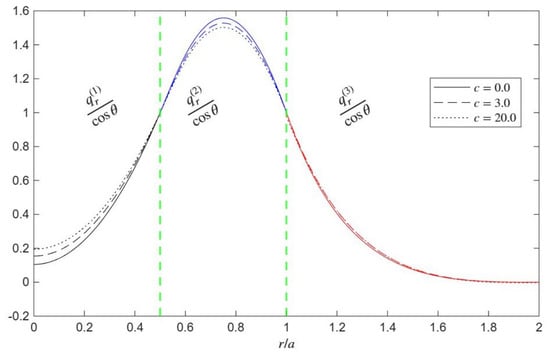
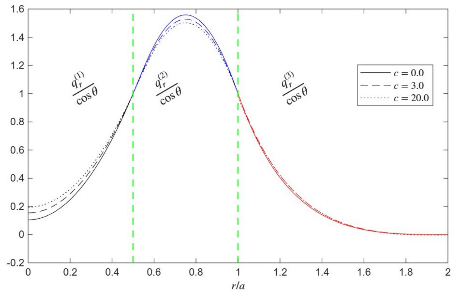
Distributions of normal velocity for micropolarity parameter c at , , , .
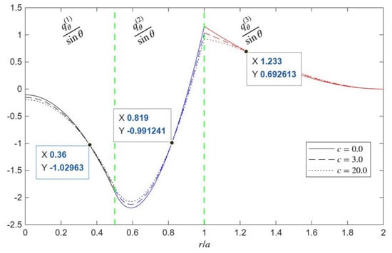
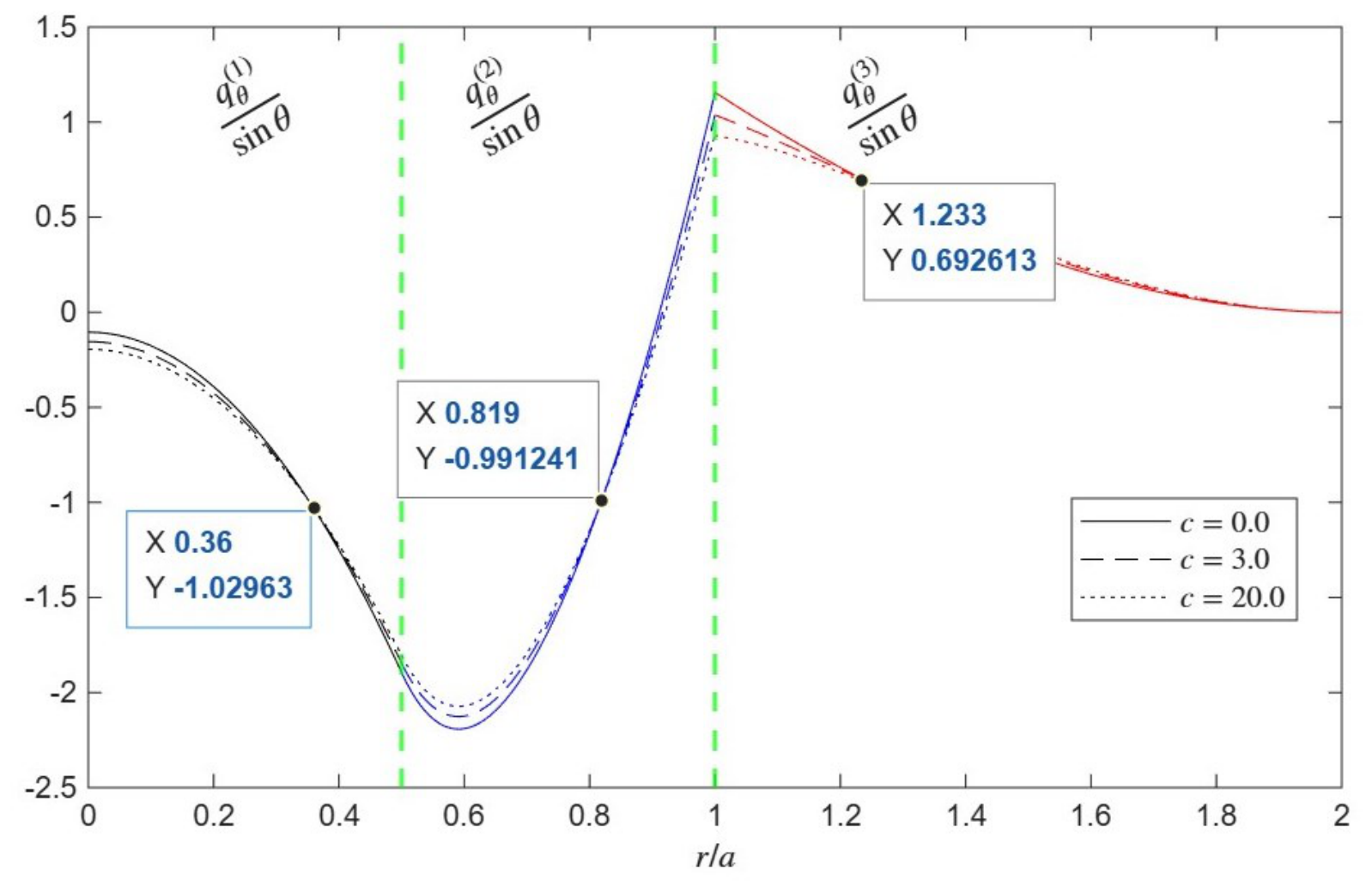
Figure 3.
Distributions of tangential velocity for micropolarity parameter c at , , , .
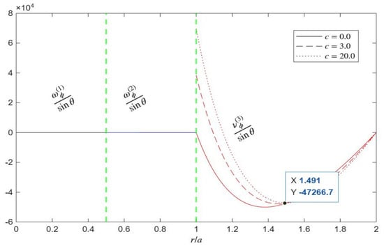
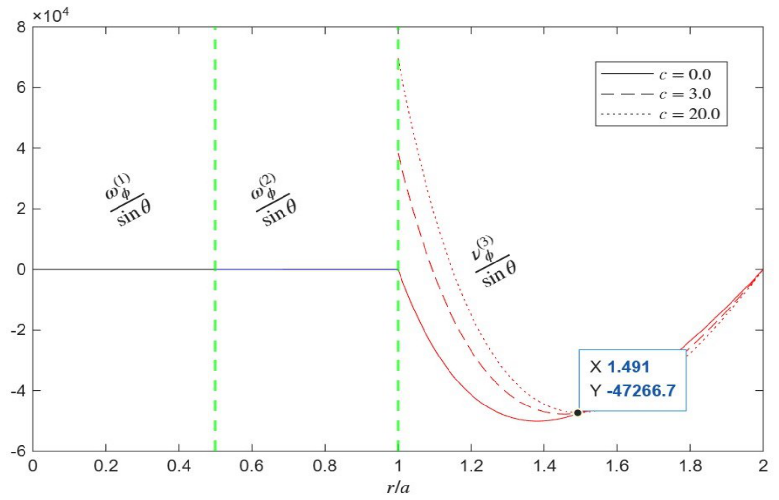
Figure 4.
Distributions of microrotation and vorticity functions for micropolarity parameter c at , , , .
Figure 5.
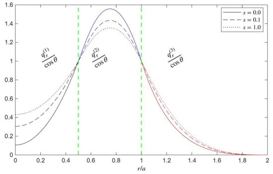
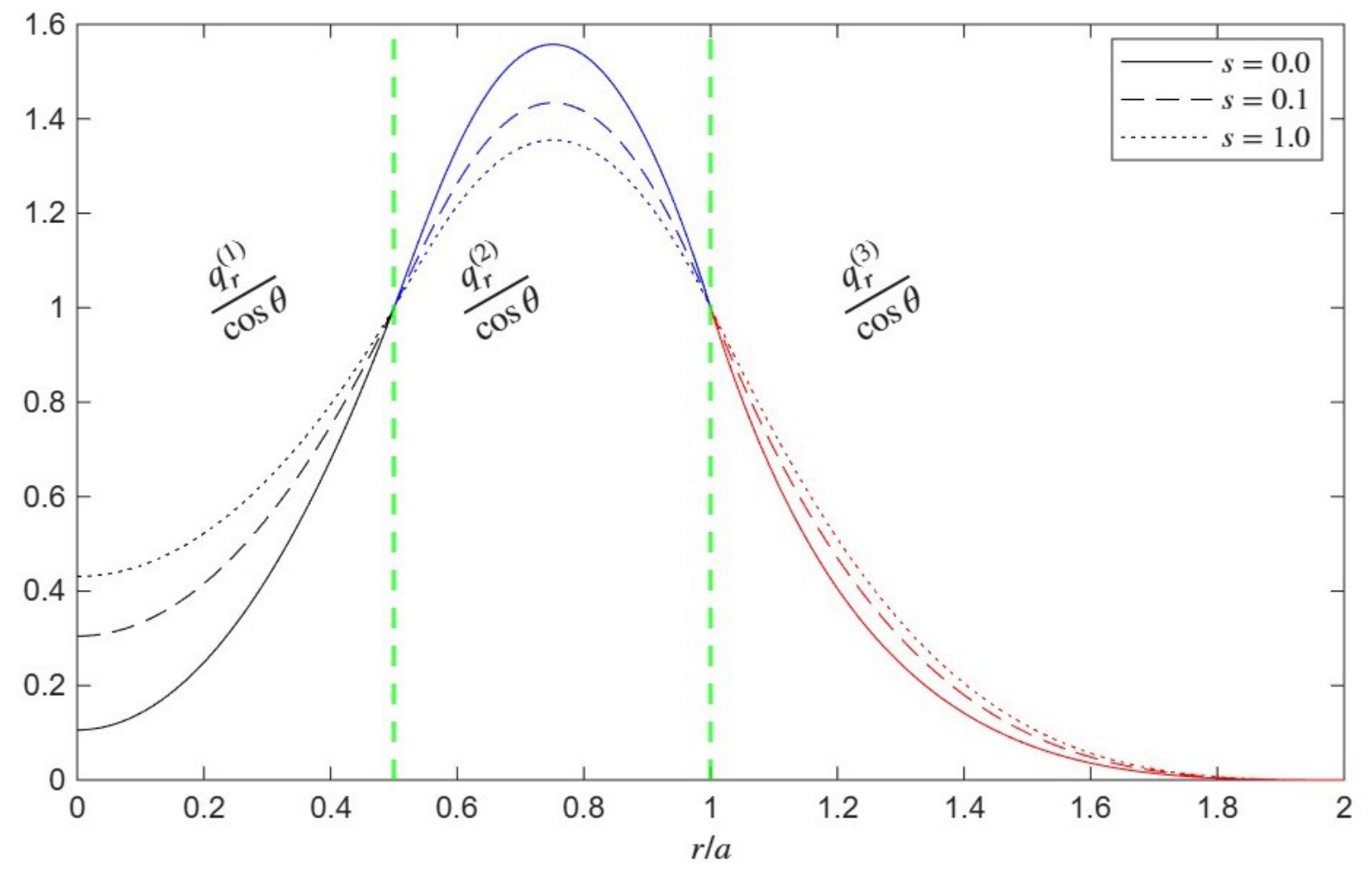
Distributions of normal velocity for spin parameter s at , , , , .
Figure 6.
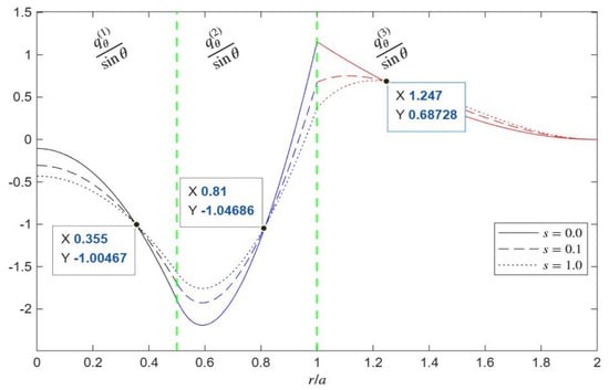
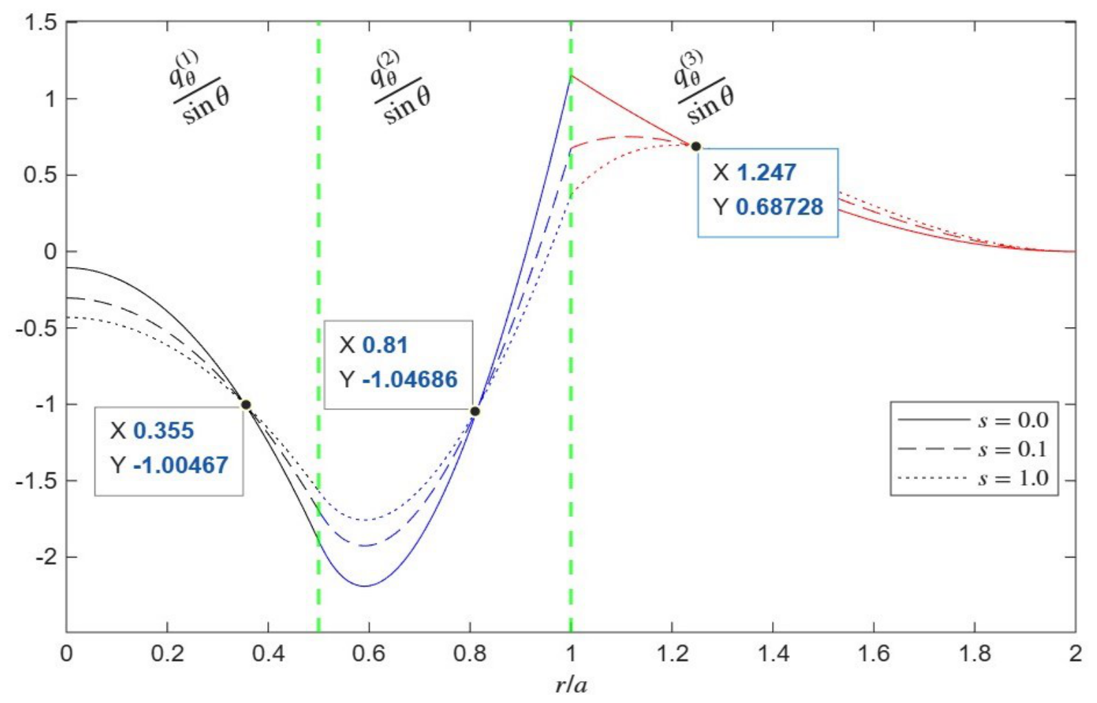
Distributions of tangential velocity for spin parameter s at , , , , and .
Figure 7.
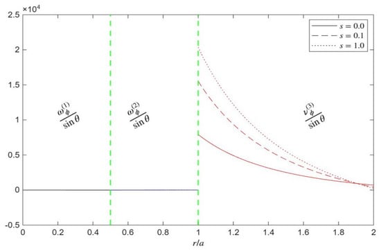
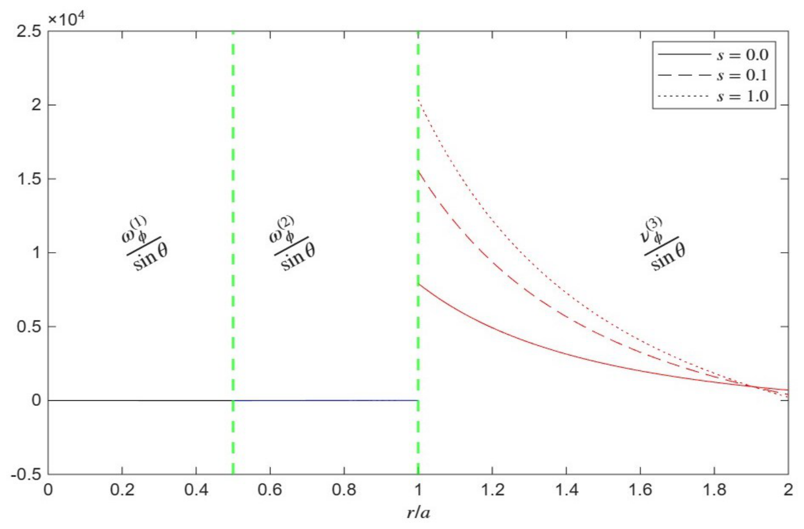
Distributions of microrotation and vorticity functions for spin parameter s at , , , , and .
Figure 8.
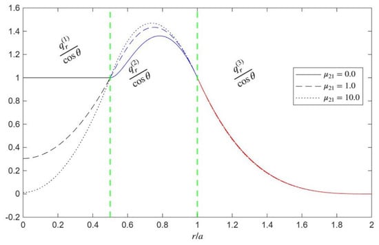
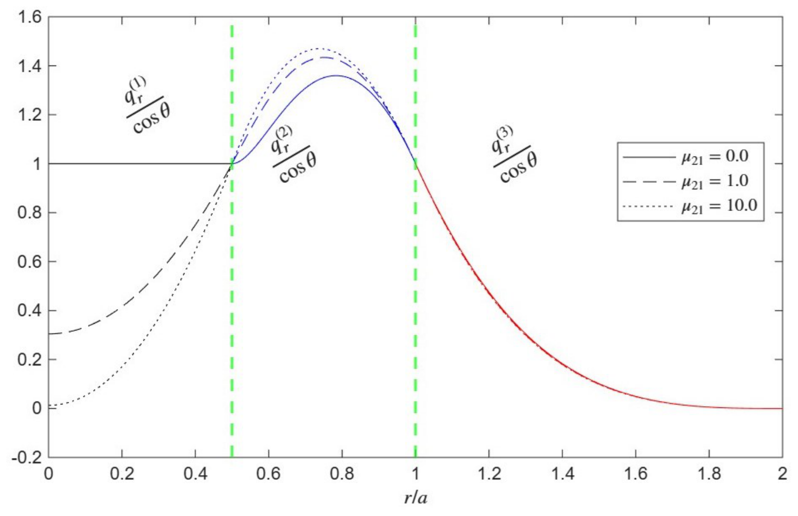
Distributions of normal velocity for dynamic viscosity at , , , , and .
Figure 9.
Distributions of tangential velocity for dynamic viscosity at , , , , and .
Figure 10.
Distributions of microrotation and vorticity functions for dynamic viscosity at , , , , and .
Figure 11.
Distributions of tangential velocity for dynamic viscosity at , , , , and .
Figure 12.
Distributions of normal velocity for dynamic viscosity at , , , , and .
Figure 13.
Distributions of microrotation function for dynamic viscosity at , , , , and .
Figure 14.
Distributions of drag force on viscous droplet shell for different thicknesses at , , , , and .
Figure 15.
Distributions of drag force on viscous droplet shell for viscosity at , , , , and .
Figure 16.
Distributions of drag force on micropolar droplet shell for different thicknesses at , , , , and .
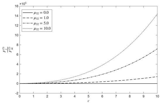
Figure 17.
Distributions of drag force on micropolar droplet shell for different at , , , , and .
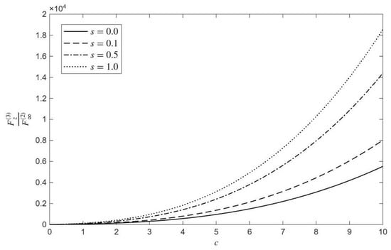
Figure 18.
Distributions of drag force on micropolar droplet shell for different s at , , , , and .
- : the micropolar shell thickness;
- : the viscous shell thickness;
- c: the micropolarity parameter;
- : the viscosity ratio between the outer viscous layer and the inner core;
- : the viscosity ratio between the micropolar cavity fluid and the viscous shell;
- s: the spin parameter;
- : the gyration viscosity.
Figure 2 illustrates the distribution of the normalized normal velocity () along the dimensionless radial coordinate (). The system is configured with moderate confinement (), equal internal and external viscosity contrasts (, ), intermediate spin coupling (), and a core size spanning half the droplet radius (). The vertical dashed lines clearly delineate the inner core, the viscous shell, and the surrounding micropolar fluid. The variations in the parameter c reveal several key physical mechanisms. Flow Dampening in the Viscous Shell (): The most prominent effect of increasing c occurs within the intermediate viscous shell (Region 2). As the micropolarity parameter increases from to , the peak normal velocity notably decreases. Physically, a higher c dictates a stronger coupling between the translational flow and the rotational motion of the microstructure in the exterior fluid. This draws more mechanical energy into the rotational degrees of freedom, creating a “stiffer” hydrodynamic resistance at the interface . This resistance propagates inward, dampening the flow development within the viscous shell. Momentum Redistribution in the Inner Core (): Near the center of the droplet, the trend slightly reverses; higher micropolarity () yields a marginally higher normal velocity compared to the Newtonian limit (). Because the fluid is incompressible and momentum transfer is continuous, the flow restriction in the viscous shell forces a redistribution of momentum. The core compensates for the dampened outer shell to satisfy overall continuity requirements. Geometric Dominance in the Exterior Region (): In the surrounding micropolar fluid (Region 3), the normal velocity curves collapse almost perfectly onto a single path, decaying to zero at the cavity wall (). This indicates that while c dramatically alters interfacial stresses and internal droplet kinematics, the normal component of the external velocity is governed primarily by mass conservation and the strict geometric constraint of the confining boundary.
Figure 3 demonstrates the distribution of the normalized tangential velocity across the three-region system under uniform viscosity ratios (, ), moderate confinement (), low spin coupling (), low gyration viscosity (), and a core size of , which isolates the pure hydrodynamic influence of the micropolarity parameter (c). Within the inner core and viscous shell, the tangential velocity exhibits a pronounced downward sweep reaching a minimum around before sharply reversing direction to peak near the outer interface (). As c increases from to , the depth of this velocity trough slightly diminishes, indicating that stronger coupling between fluid translation and microstructural rotation absorbs a fraction of the shear stress to alter the compound droplet’s internal circulation pattern. A sharp change in slope and a distinct velocity peak occur at the outer boundary (), where higher micropolarity values modify how effectively tangential momentum is diffused across the interface. In the surrounding micropolar fluid, the tangential velocity decays smoothly from its interfacial peak down to zero at the confining cavity wall (), with near-interface variations in c demonstrating that microstructural rotation extends its influence before satisfying the boundary conditions at the cavity.
Figure 4 illustrates the distribution of the normalized microrotation function across the three-region system for different values of the micropolarity parameter (c) under conditions of uniform viscosity ratios (, ), moderate confinement (), low spin coupling (), low gyration viscosity (), and a core size of . Within the inner core and the viscous shell (), the microrotation remains identically zero because these inner domains consist of classical fluids devoid of microstructural degrees of freedom. In contrast, within the surrounding micropolar fluid (), the microrotation function exhibits a sharp positive peak immediately at the outer interface (), before dropping steeply to form a negative trough (reaching a minimum value of around ) and ultimately decaying back to zero at the confining cavity wall (). As the micropolarity parameter c increases from to , both the interfacial peak and the magnitude of the negative trough significantly increase, demonstrating that stronger microstructural coupling amplifies the rotational response and angular momentum transfer within the exterior fluid layer. It is worth noting that the magnitudes of the microrotation and vorticity functions reach values on the order of , which is significantly higher than the normalized velocity components (). This scaling behavior is physically rooted in Eringen’s micropolar theory, where intense local spin and angular momentum transfer can concentrate heavily at boundaries and interfaces independently of the macroscopic translational flow. Furthermore, extending the micropolarity parameter up to captures extreme microstructural coupling regimes (such as dense suspensions) and asymptotic limits, while confirming that the underlying linear system remains stable and free from numerical singularities.
Figure 5 exhibits the distribution of the normalized normal velocity () across the three-region system for different values of the spin parameter (s) at , , , , , and . Within the inner core (), increasing the spin parameter from to noticeably elevates the normal velocity near the center, shifting the starting value from approximately up to . All curves converge smoothly at the first internal interface (). Within the viscous shell (), the normal velocity rises to a pronounced peak; however, increasing s significantly suppresses this maximum value, reducing the peak from roughly for the no-spin case () down to about for strongest kinematic coupling (). The curves converge once more at the outer boundary (). In the surrounding micropolar fluid (), the normal velocity decays smoothly to zero at the confining cavity wall (), demonstrating that the spin parameter primarily modulates the internal core and shell kinematics while exerting a minimal effect on the outer fluid’s decay profile.
Figure 6 explains the distribution of the normalized tangential velocity () across the three-region system for different values of the spin parameter (s) at , , , , , and . Within the inner core () and the viscous shell (), the tangential velocity profiles exhibit a deep downward sweep, forming a pronounced trough around . Increasing the spin parameter from to significantly attenuates the depth of this velocity trough—raising the minimum value from approximately −2.2 down to around —and alters the curves through an intersection point near (, ). At the outer boundary (), the tangential velocity reaches a sharp positive peak for the no-spin case (), whereas higher spin coupling () substantially suppresses this interfacial peak. In the surrounding micropolar fluid (), the velocity curves decay smoothly from their interfacial values down to zero at the confining cavity wall (). This behavior demonstrates that the spin parameter s effectively regulates the transfer of angular momentum and the degree of kinematic coupling at the viscous–micropolar interface, directly reshaping the internal and near-wall tangential flow field.
Figure 7 elucidates the spatial distributions of the classical fluid vorticity functions ( and ) in Regions 1 and 2 alongside the independent microrotation function () in Region 3 for varying spin parameter values (, , and ). In the inner core and viscous shell (Regions 1 and 2, rendered in black and blue, respectively), the normalized vorticity remains identically zero across all spin values, confirming that these classical Newtonian domains lack the microstructural degrees of freedom required to support intrinsic spin. Conversely, a sharp transition occurs at the outer droplet interface (), where the independent microrotation field in the surrounding micropolar fluid (Region 3, rendered in red) initiates. Increasing the spin-coupling parameter s significantly amplifies this interface microrotation—ranging from approximately at to a peak of at —before all curves decay monotonically toward zero as they approach the outer boundary limit ().
Figure 8 illustrates the distribution of the normalized normal velocity () across the three-region system for different values of the viscosity ratio parameter () at , , , , , and . Within the inner core (), the viscosity ratio exerts a profound influence on the flow profile. For the limiting case of (solid line), the normal velocity remains completely flat and constant at . As increases to (dashed line) and (dotted line), the velocity at the center drops significantly—starting near and , respectively—before rising to meet at a common value of at the first internal interface (). Within the viscous shell (), the normal velocity profiles rise to form a peak around . Higher values of slightly elevate this peak velocity within the shell, reflecting the altered resistance to deformation due to the viscosity mismatch between the outer layer and the core. All curves converge once again at the outer boundary (). In the surrounding micropolar fluid (), the three curves completely collapse into a single trajectory, decaying smoothly to zero at the confining cavity wall (). This demonstrates that variations in the internal viscosity ratio directly govern the kinematics within the inner core and viscous shell, while having a negligible impact on the velocity distribution of the outer micropolar medium.
Figure 9 explicates the distribution of the normalized tangential velocity () across the three-region system for different values of the viscosity ratio parameter () at , , , , , and . Within the inner core (), the viscosity ratio significantly alters the tangential flow. For the limiting case of (solid line), the tangential velocity remains completely flat and constant at . As increases to (dashed line) and (dotted line), the velocity drops more steeply toward the first internal interface, passing through a common region near (, ). Within the viscous shell (), all profiles sweep downward to form a pronounced trough near with a minimum value around . Higher values of slightly deepen this trough due to the increased resistance to deformation within the outer layer. Near the outer boundary (), the velocity curves rise sharply into positive values. In the surrounding micropolar fluid (), the three curves completely collapse into a single unified trajectory, passing through a marked point at (, ) before decaying smoothly to zero at the confining cavity wall (). This demonstrates that variations in the internal viscosity ratio directly govern the tangential kinematics and shear distribution within the inner core and viscous shell, while having a negligible impact on the outer micropolar fluid layer.
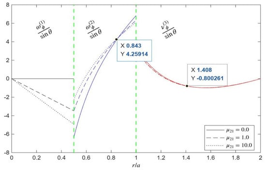
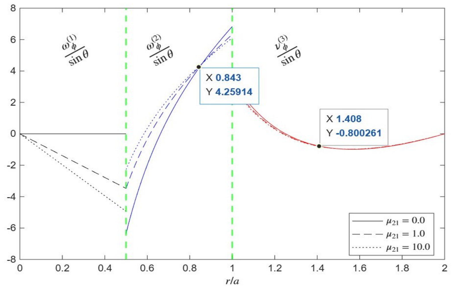
Figure 10 elucidates the spatial distributions of the classical fluid vorticity functions ( and ) and the independent microrotation function () for varying dynamic viscosity ratios () at fixed parameters , , , , , and . In the inner core (Region 1, ), the vorticity profiles diverge significantly depending on , transitioning from a flat zero baseline at to substantial negative values reaching approximately at the inner interface when . Across the inner interface (), sharp discontinuities appear in the viscous shell (Region 2), where the vorticity curves initiate strongly negative before rising steeply, intersecting common reference points near , and peaking at the outer boundary () between approximately and . Finally, upon transitioning into the surrounding micropolar fluid (Region 3, ), the independent microrotation profiles drop sharply, dip to a quantified minimum near , and subsequently decay smoothly toward zero as they approach the outer boundary limit ().
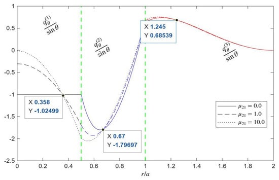
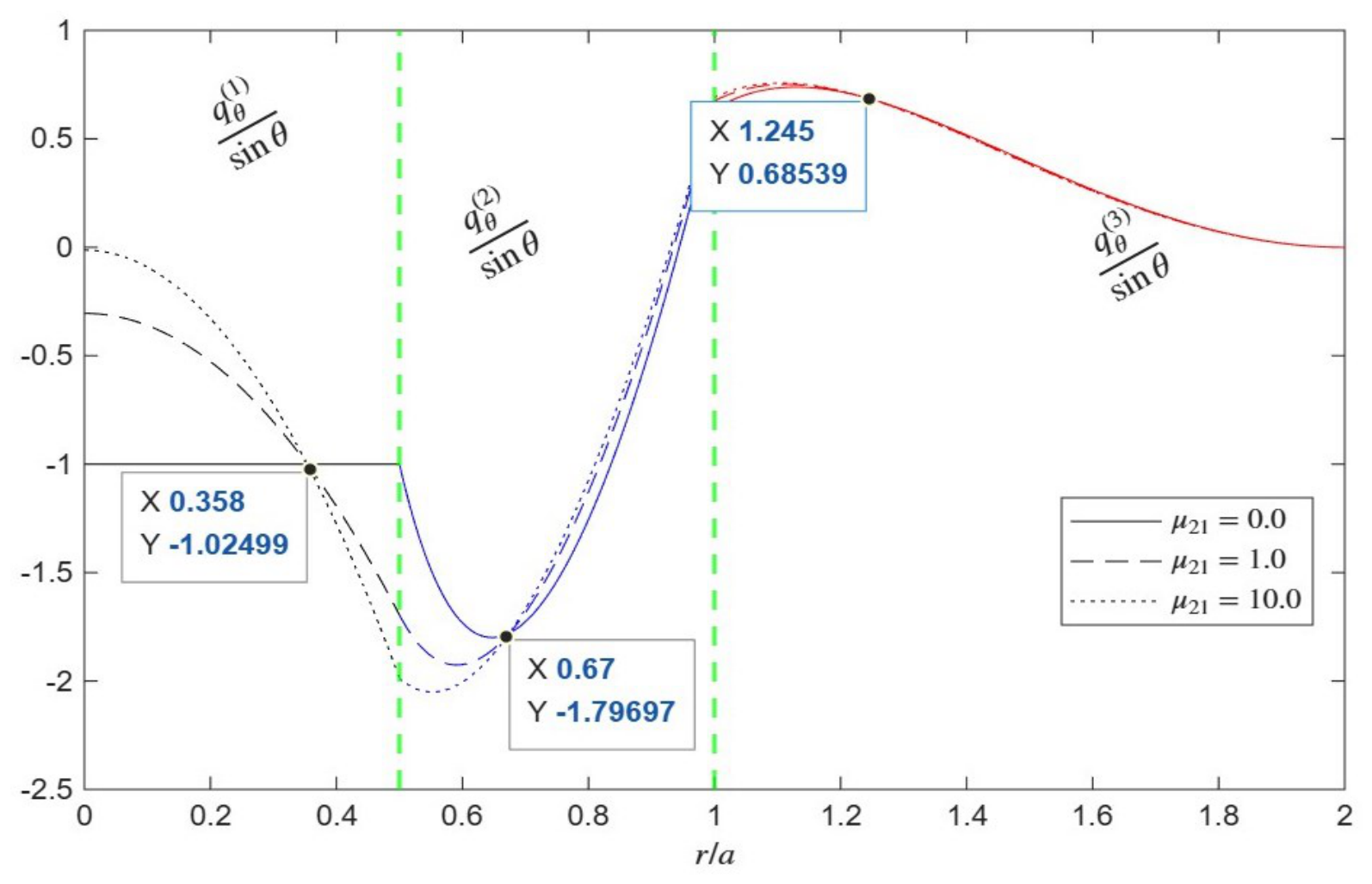
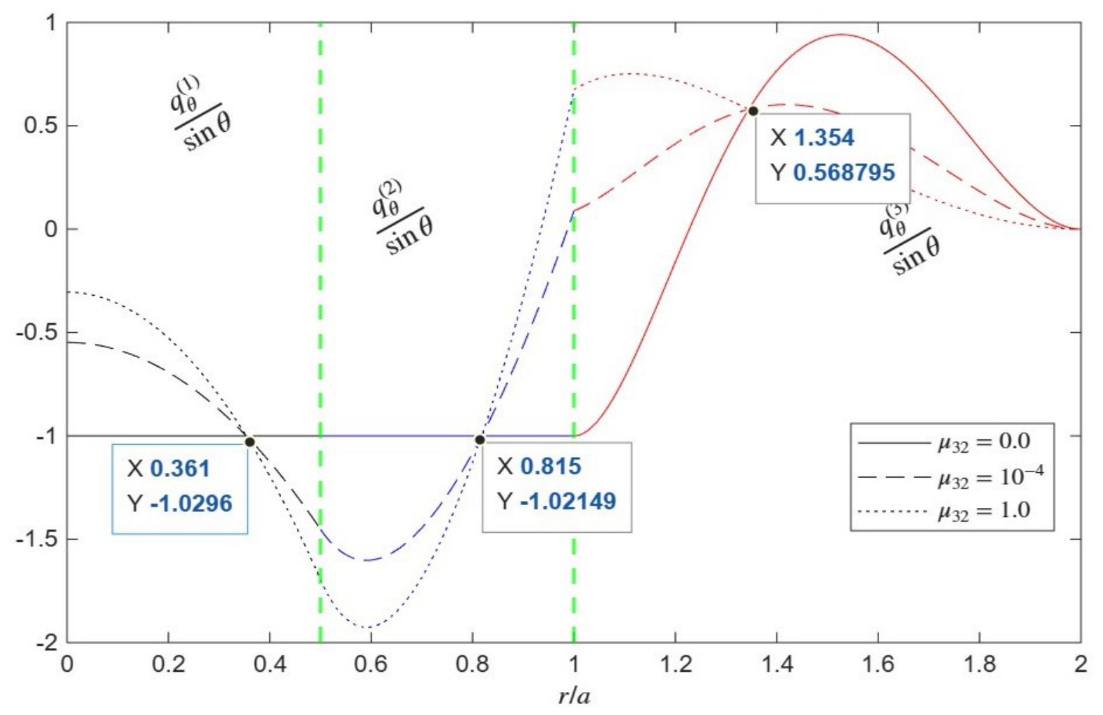
Figure 11 illustrates the distribution of the normalized tangential velocity () across the three-region system for different values of the viscosity ratio parameter () at , , , , , and . Within the inner core (), the viscosity ratio significantly alters the tangential velocity profile. For the limiting case of (solid line), the velocity remains completely flat and constant at . As increases to (dashed line) and (dotted line), the central velocity shifts upward (starting near and , respectively) before decreasing steeply toward the first internal interface, passing through a common region near (, ). Within the viscous shell (), all profiles sweep downward to form a pronounced trough near . Specifically, for , this trough reaches a deeper minimum of approximately . The curves then rise toward the outer boundary (), passing through another intersection region near (, ). In the surrounding micropolar fluid (), variations in exert a profound influence on the outer flow behavior—unlike the internal viscosity ratio , which had minimal effect here. For (dotted line), the velocity rises sharply just past the interface into a localized peak before decaying. For smaller values ( and ), the curves rise more gradually to a broader peak around (, ) before decaying smoothly to zero at the confining cavity wall (). This demonstrates that the viscosity contrast with the exterior micropolar fluid is a primary governing factor in determining how efficiently tangential momentum is transmitted across the outer interface and distributed throughout the confining cavity.
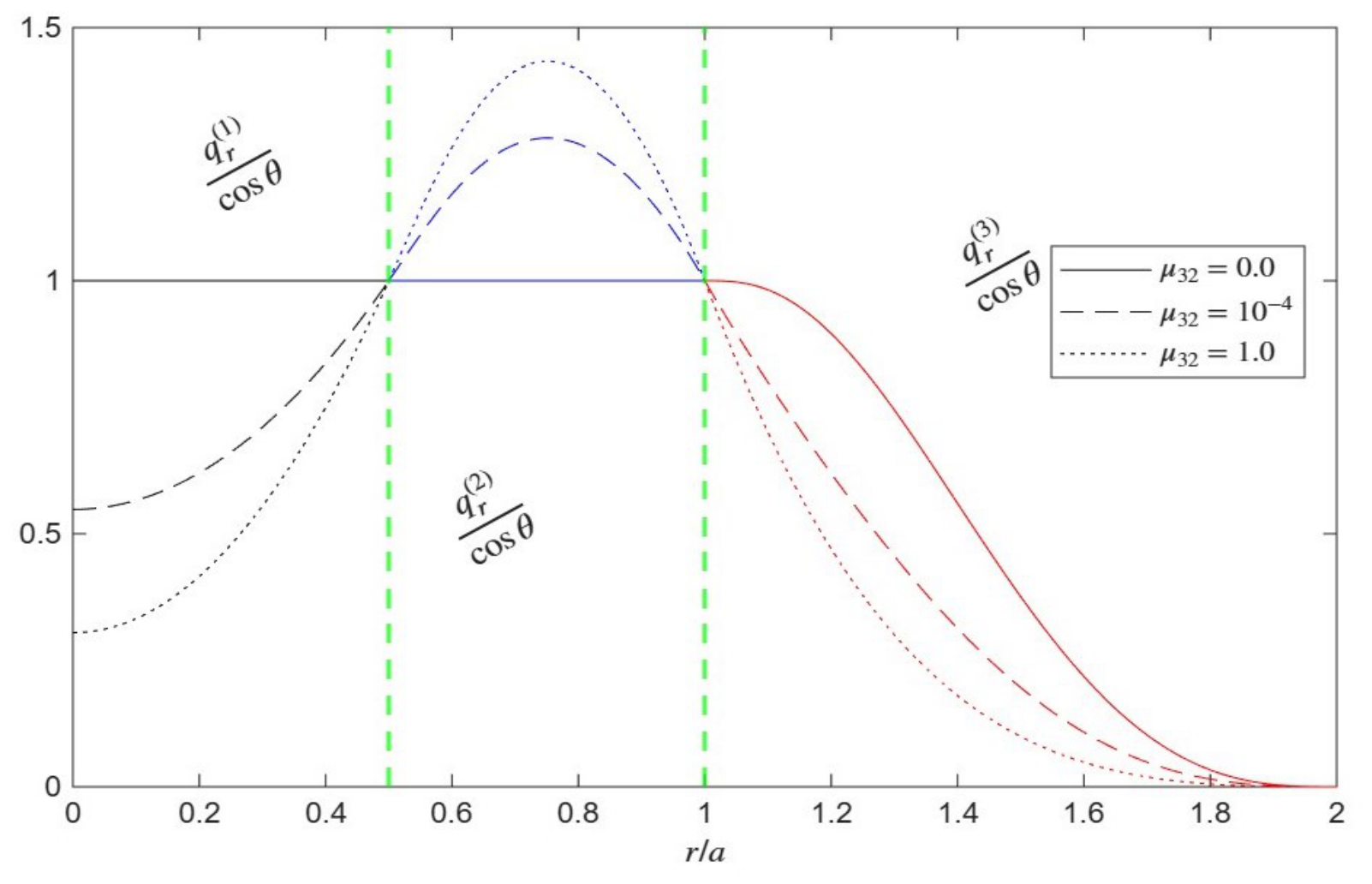
Figure 12 describes the distribution of the normalized normal velocity () across the three-region system for different values of the viscosity ratio parameter () at , , , , , and . Within the inner core (), the viscosity ratio significantly affects the normal velocity profile. For the limiting case of (solid line), the normal velocity remains completely flat and constant at across both the inner core and the viscous shell up to . As increases to (dashed line) and (dotted line), the central velocity drops (starting near and , respectively) before rising to meet at at the first internal interface (). Within the viscous shell (), the profiles for non-zero rise to form a distinct peak near , with higher values of (such as ) generating a higher peak velocity of approximately . All curves converge once again to at the outer boundary (). In the surrounding micropolar fluid (), variations in markedly alter the decay behavior. For (solid line), the normal velocity maintains a value of slightly past the interface before decaying smoothly to zero at the cavity wall (). For higher values like (dotted line), the velocity decays much more steeply directly from the outer interface. This demonstrates that the viscosity contrast with the exterior micropolar fluid plays a critical role in governing the normal velocity distribution and momentum transmission across the outer boundary.
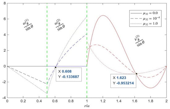
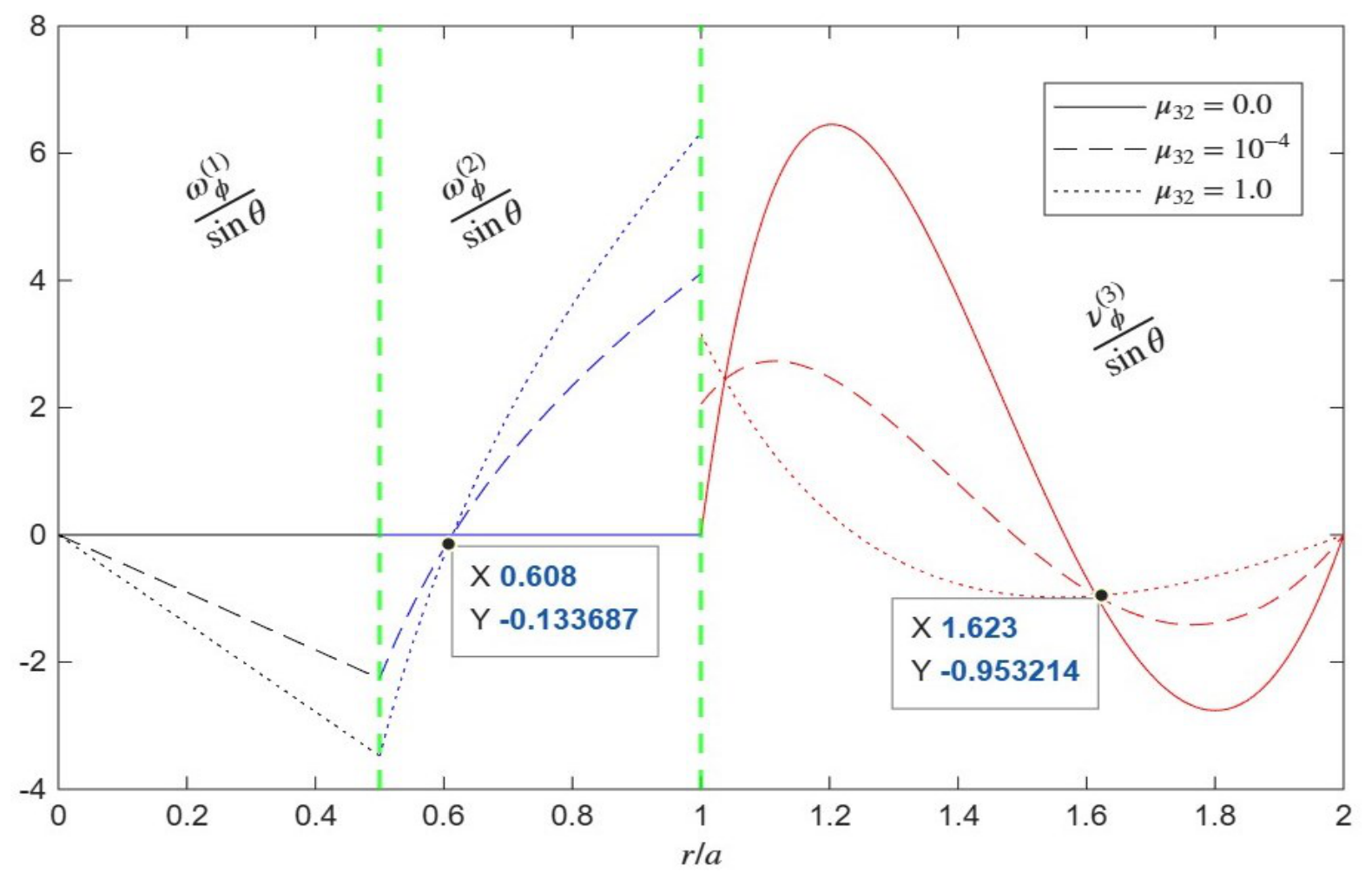
Figure 13 illustrates the distribution of the normalized microrotation function across the three-region system for different values of the viscosity ratio parameter () at , , , , , and . Within the inner core (), the microrotation function remains flat at zero for the limiting case of (solid line). However, for (dashed line) and (dotted line), the profile decreases linearly into negative values at the first internal interface (). Within the viscous shell (), the microrotation function for non-zero rises sharply from its interfacial negative starting point, passes through a common intersection point at (, ), and culminates in distinct positive peaks at the outer boundary (). For , the microrotation remains identically zero across both the inner core and the viscous shell. In the surrounding micropolar fluid (), variations in profoundly alter the outer microrotation profile (). For (solid red line), the function starts at zero at the interface, rises to a prominent positive peak near , drops through zero, and forms a deep negative trough near before returning to zero at the confining cavity wall (). For higher viscosity ratios like (dotted line), the curve starts at a positive value at the interface, intersects other profiles near (, ), and decays smoothly to zero at the cavity wall. This demonstrates that the outer viscosity contrast strongly dictates the transmission of angular momentum and the rotational response within the surrounding micropolar medium.
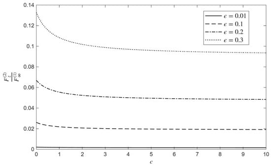
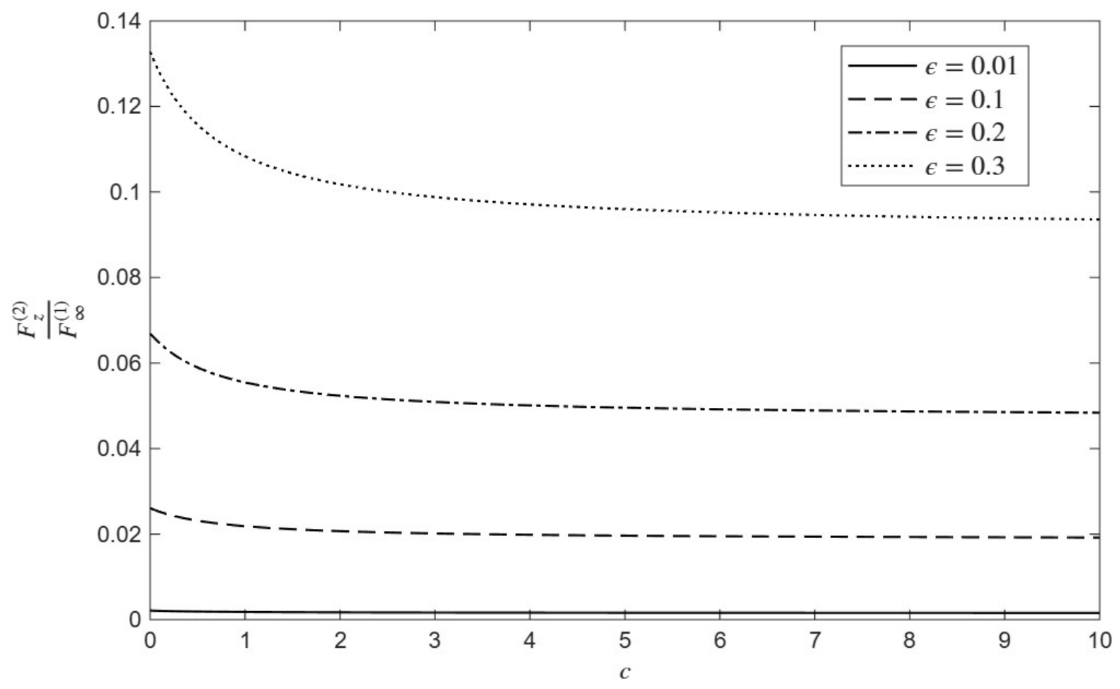
Figure 14 shows the distribution of the normalized drag force on the viscous droplet shell () as a function of the micropolarity parameter (c) for different core-size parameters () under fixed conditions of , , , , and . Increasing substantially raises the normalized drag force across the entire range of c because an expanded inner core and a thinner viscous shell modify the internal distribution of viscous resistance and momentum transfer, leading to a higher overall drag penalty relative to the unbounded reference configuration. Concurrently, as c increases from 0 to 10, the normalized drag force experiences a slight decrease—most notably within the lower range ()—before asymptotically leveling off into a nearly constant plateau, demonstrating that stronger coupling between fluid translation and microstructural rotation absorbs mechanical energy and eases the hydrodynamic resistance transmitted to the viscous shell.
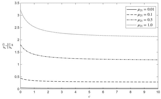
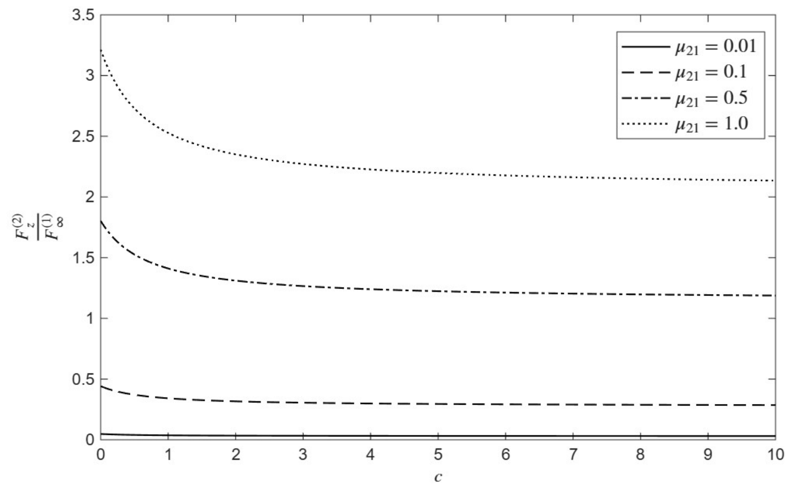
Figure 15 illustrates the distribution of the normalized drag force on the viscous droplet shell () as a function of the micropolarity parameter (c) for different values of the viscosity ratio parameter () under fixed conditions of , , , , and . Increasing the viscosity ratio substantially raises the normalized drag force across the entire range of c. Because a higher inner-core viscosity increases the resistance to deformation and internal momentum transfer, the overall drag penalty on the viscous shell grows significantly. Concurrently, as c increases from 0 to 10, the normalized drag force experiences a slight decrease—most notably within the lower range ()—before leveling off into a nearly constant plateau. This demonstrates that stronger coupling between fluid translation and microstructural rotation absorbs mechanical energy and eases the hydrodynamic resistance transmitted to the viscous shell, consistent across all examined inner-core viscosity ratios.
Figure 16 interprets the distribution of the normalized drag force on the micropolar droplet shell () as a function of the micropolarity parameter (c) for different values of the core-size parameter () under fixed conditions of , , , , and . As the micropolarity parameter c increases from 0 to 10, the normalized drag force experiences a sharp, non-linear upward surge across all configurations, ultimately reaching values up to approximately at for the highest core-size parameter.
Furthermore, increasing substantially elevates the normalized drag force throughout the range of c, demonstrating that a larger inner core size significantly amplifies the hydrodynamic resistance and drag penalty experienced by the micropolar shell relative to the reference configuration.
Figure 17 describes the distribution of the normalized drag force on the micropolar droplet shell () as a function of the micropolarity parameter (c) for different values of the viscosity ratio parameter () under fixed conditions of , , , , and . As the micropolarity parameter c increases from 0 to 10, the normalized drag force experiences a sharp, non-linear upward surge across all non-zero viscosity ratios. Furthermore, increasing the outer viscosity ratio substantially elevates the drag force across the entire range of c. For the limiting case of , the normalized drag force remains flat and close to zero, whereas for higher values like , the drag force scales up dramatically, reaching magnitudes of approximately at . This demonstrates that the viscosity contrast with the exterior medium and stronger microstructural coupling synergistically amplify the hydrodynamic resistance and drag penalty experienced by the micropolar droplet shell.
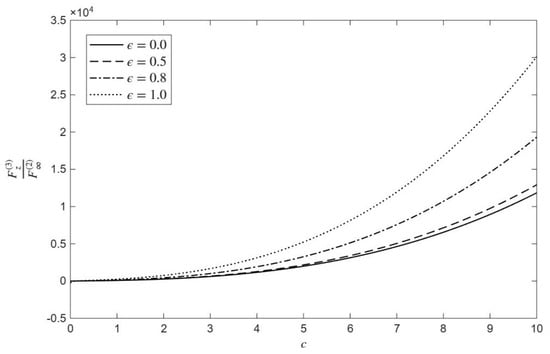
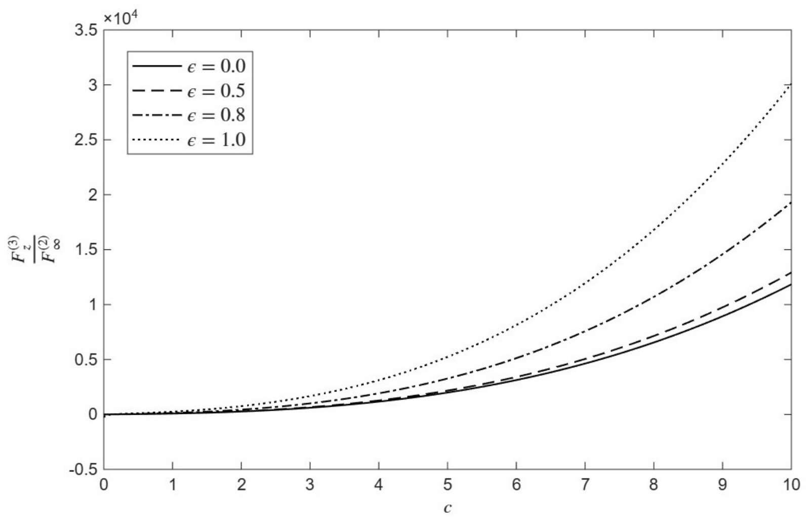
Figure 18 demonstrates the distribution of the normalized drag force on the micropolar droplet shell () as a function of the micropolarity parameter (c) for different values of the spin parameter () under fixed conditions of , , , , and . As the micropolarity parameter c increases from 0 to 10, the normalized drag force experiences a sharp, non-linear upward surge across all spin parameters. Furthermore, increasing the spin parameter s substantially elevates the drag force across the entire range of c. For lower spin values like , the drag force increases more gradually, whereas higher kinematic coupling like scales up the drag force significantly, reaching magnitudes of approximately at . This demonstrates that stronger spin coupling and microstructural rotation synergistically amplify the hydrodynamic resistance and drag penalty experienced by the micropolar droplet shell.
A notable observation in the distribution of the microrotation function is that its magnitudes reach orders of near the outer interface (e.g., as illustrated in Figure 4 and Figure 7). To clarify the physical significance of these large values, it is important to emphasize that they do not represent mere mathematical artifacts, but rather correspond to extreme, physically realistic microstructural coupling regimes—such as dense polymeric suspensions or specialized biological fluids possessing strong internal rotational inertia—as well as asymptotic boundary limits. Specifically, micropolarity parameter values up to are utilized to capture these extreme microstructural coupling regimes and asymptotic limits relevant to dense industrial and biological suspensions. Meanwhile, the spin parameter s, bounded between 0 and 1, spans the complete physical spectrum of boundary constraints, ranging from zero surface spin to full kinematic freedom. The physical origin of this behavior is well-founded in Eringen’s micropolar theory: intense local spin and angular momentum transfer can concentrate heavily at boundaries and interfaces independently of macroscopic translational flow, ensuring that the underlying linear system remains stable and physically consistent across these operational ranges. On the other hand, the observed graphical trends relate to fundamental hydrodynamic and microstructural phenomena:
- Rather than just noting velocity drops, the text explicitly explains that higher c values increase the coupling between fluid translation and microstructural rotation, drawing mechanical energy into rotational degrees of freedom. This creates a “stiffer” hydrodynamic resistance at the interface () that dampens shell flow, while forcing momentum redistribution within the inner core to satisfy continuity requirements.
- The discussion now clarifies that variations in s directly regulate the transfer of angular momentum and the efficiency of kinematic coupling at the viscous–micropolar interface, which explains the attenuation of peak normal and tangential velocities within the viscous shell.
- The text distinguishes between the internal viscosity ratio ()—which dictates deformation resistance and internal kinematics within the core and shell—and the outer viscosity ratio (), which acts as the primary governor determining how efficiently momentum is transmitted across the outer interface and distributed throughout the confining cavity, driving the sharp non-linear surge in drag forces.
4. Conclusions
The present investigation provides a comprehensive hydrodynamic characterization of a compound droplet immersed in a micropolar fluid across three concentric regions, elucidating the critical influence of governing microstructural and operational parameters on velocity profiles, rotational fields, and drag forces. The analysis demonstrates that increasing the micropolarity parameter c and the spin parameter s enhances fluid–microstructure coupling, which dampens peak normal and tangential velocities within the viscous shell while intensifying outer microrotation fields. Furthermore, variations in the inner and outer dynamic viscosity ratios ( and ) profoundly govern internal shear distributions, core vorticity behaviors, and momentum transmission across interfaces. Hydrodynamic drag responses exhibit marked contrasts: the normalized drag on the viscous droplet shell decreases moderately with c before leveling off into an asymptotic plateau, whereas the normalized drag on the outer micropolar shell experiences a dramatic, non-linear upward surge at high micropolarity that is heavily amplified by larger core-size parameters (), outer viscosity contrasts (), and spin coupling (s). These quantitative insights provide robust predictive guidelines for designing tunable microcapsules and compound droplets in microfluidic applications, biological suspensions, and emulsions, while confirming the model’s capacity to smoothly recover classical Newtonian limits under asymptotic conditions. It is worth noting that interfacial tension and droplet deformation are neglected in the present formulation to maintain mathematical tractability and obtain closed-form solutions. This assumes that capillary forces are sufficiently dominant to preserve the spherical integrity of the concentric layers, restricting the analysis to non-deformable interfaces under creeping-flow conditions.
Funding
The author extends his appreciation to the Deanship of Scientific Research and Libraries in Princess Nourah bint Abdulrahman University for funding this research work through the Supporting Publication in Top-Impact Journals Initiative (SPTIF-2026).
Data Availability Statement
The original contributions presented in this study are included in the article. Further inquiries can be directed to the corresponding author.
Conflicts of Interest
The author declares no conflicts of interest.
References
- Stokes, G.G. On the Effect of the Internal Friction of Fluids on the Motion of Pendulums. Trans. Camb. Philos. Soc. 1851, 9, 8–106. [Google Scholar] [CrossRef] [Scilit]
- Happel, J.; Brenner, H. Low Reynolds Number Hydrodynamics: With Special Applications to Particulate Media; Springer: Berlin/Heidelberg, Germany, 1983. [Google Scholar]
- Kim, S.; Karrila, S.J. Microhydrodynamics: Principles and Selected Applications; Dover: Mineola, NY, USA, 2005. [Google Scholar]
- Eringen, A.C. Theory of micropolar fluids. Ind. Univ. Math. J. 1966, 16, 1–18. [Google Scholar] [CrossRef] [Scilit][Green Version]
- Eringen, A.C. Microcontinuum Field Theories II: Fluent Media; Springer: Berlin/Heidelberg, Germany, 2001. [Google Scholar]
- Brinkman, H.C. A calculation of the viscous force exerted by a flowing fluid on a dense swarm of particles. Appl. Sci. Res. 1949, 1, 27–34. [Google Scholar] [CrossRef] [Scilit]
- El-Sapa, S.; Faltas, M.S.; Ragab, K.E. Coupled thermal and interfacial effects on the motion of a compound droplet near a planar surface. Phys. Fluids 2026, 38, 053112. [Google Scholar] [CrossRef] [Scilit]
- Ragab, K.E.; El-Sapa, S.; Faltas, M.S. Interfacial dynamics of a composite spherical particle between microstructured and viscous fluids. Phys. Fluids 2025, 37, 122017. [Google Scholar] [CrossRef] [Scilit]
- Sherief, H.H.; Faltas, M.S.; El-Sapa, S. A general formula for the drag on a solid of revolution body at low Reynolds numbers in a microstretch fluid. Meccanica 2017, 52, 2655–2664. [Google Scholar] [CrossRef] [Scilit]
- El-Sapa, S. Effect of magnetic field on a microstretch fluid drop embedded in an unbounded another microstretch fluid. Eur. J. Mech. B/Fluids 2021, 85, 169–180. [Google Scholar] [CrossRef] [Scilit]
- Sherief, H.H.; Faltas, M.S.; El-Sapa, S. Slow motion of a slightly deformed spherical droplet in a microstretch fluid. Microsys. Technol. 2018, 24, 3245–3259. [Google Scholar] [CrossRef] [Scilit]
- El-Sapa, S. Settling slip velocity of a spherical particle in an unbounded micropolar fluid. Eur. Phys. J. E 2019, 42, 32. [Google Scholar] [CrossRef] [Scilit] [PubMed]
- Yang, H.; Knowles, T.P.J. Flow behavior of a droplet in viscous fluids through asymmetric bifurcating microchannels. Phys. Fluids 2026, 38, 012011. [Google Scholar] [CrossRef] [Scilit]
- Hermes, M.; Skoda, R. Effect of droplet size on the fluctuation velocity of single droplets suspended in forced homogeneous isotropic turbulent flow. Exp. Comput. Multiph. Flow 2026, 8, 743–771. [Google Scholar] [CrossRef] [Scilit]
- Ma, L.; Zhao, X.; Hou, J.; Xiao, Y.; Lu, X.; Chen, Z.; Wei, J.; Hao, N. Droplet microfluidics for biomedical applications: Emerging trends and future developments. Microsyst. Nanoeng. 2026, 12, 53. [Google Scholar] [CrossRef] [Scilit] [PubMed]
- Chauchat, A.; Le Bars, M.; Meunier, P. A fully nonlinear solution of the flow around a spinning spheroid in a rotating stratified fluid. J. Fluid Mech. 2021, 1018, A44. [Google Scholar] [CrossRef] [Scilit]
- Liu, Y.; Chen, G.; Chen, W.-L.; Gao, D.; Kim, K.C. Flow control of a square cylinder at the most unfavorable angle of attack via bionic shark scales. Phys. Fluids 2026, 38, 065145. [Google Scholar] [CrossRef] [Scilit]
- Saad, E.; Faltas, M.S. Transient response of a hydrophobic colloidal particle in a micropolar fluid. Int. J. Eng. Sci. 2026, 227, 104591. [Google Scholar] [CrossRef] [Scilit]
- Ashmawy, E.A.; Faltas, M.S.; Othman, H.A. Dynamics of rotational oscillations of colloidal particle pairs in micropolar fluids under slip conditions. Eur. Phys. J. Plus 2026, 141, 648. [Google Scholar] [CrossRef] [Scilit]
- Faltas, M.S.; Ashmawy, E.A.; Nashwan, M.G.; Ahmed, B.A.; El-Sayed, M. Coupled thermophoretic and thermocapillary effects on the motion of a particle near an immiscible fluid interface. Case Stud. Therm. Eng. 2023, 50, 107852. [Google Scholar] [CrossRef] [Scilit]
- Faltas, M.S.; Ashmawy, E.A.; Mahrous, S.A.; Sayed, M.M.E.; Ragab, K.E. Thermophoresis of a spherical particle straddling a flat interface in a Brinkman medium at a 90° contact angle. Eur. J. Mech.-B/Fluids 2024, 104, 204–441. [Google Scholar] [CrossRef] [Scilit]
- Saad, E.I.; Faltas, M.S.; Ashmawy, E.A.; Ghallap, R.S. Boundary effects on the thermocapillary motion of a fluid droplet in a porous medium. Chin. J. Phys. 2025, 98, 529–545. [Google Scholar] [CrossRef] [Scilit]
- Ayman, M.; Saad, E.I.; Faltas, M.S. Transient motion of a rotating slippery spherical particle within a spherical cavity filled with a porous medium. Can. J. Phys. 2025, 103, 638–653. [Google Scholar] [CrossRef] [Scilit]
- Ragab, K.E.; Faltas, M.S. The creeping movement of a soft colloidal particle normal to a planar interface. Phys. Fluids 2024, 36, 072106. [Google Scholar] [CrossRef] [Scilit]
- Ragab, K.E.; Nashwan, M.G.; Faltas, M.S. Axisymmetric Stokes flow of a spherical droplet or slip particle in the presence of a circular disk. Chin. J. Phys. 2024, 88, 154–170. [Google Scholar] [CrossRef] [Scilit]
- Subramanian, R.S. Thermocapillary migration of bubbles and droplets. Adv. Space Res. 1983, 3, 145–153. [Google Scholar] [CrossRef] [Scilit]
- Tran-Son-Tay, R.; Needham, D.; Yeung, A.; Hochmuth, R.M. Time-dependent recovery of passive neutrophils after large deformation. Biophys. J. 1991, 60, 856–866. [Google Scholar] [CrossRef] [Scilit] [PubMed]
- Yeung, A.; Evans, E. Cortical shell-liquid core model for passive flow of liquid-like spherical cells into micropipets. Biophys. J. 1989, 56, 139–149. [Google Scholar] [CrossRef] [Scilit] [PubMed]
- Balasubramaniam, R.; Subramanian, R.S. The migration of a drop in a uniform temperature gradient at large marangoni numbers. Phys. Fluids 2000, 12, 733–743. [Google Scholar] [CrossRef] [Scilit][Green Version]
- Behera, N.; Poddar, A.; Chakraborty, S. Eccentricity-induced dielectrophoretic migration of a compound drop in a uniform external electric field. J. Fluid Mech. 2023, 963, A17. [Google Scholar] [CrossRef] [Scilit]
- Bickel, T. Hindered mobility of a particle near a soft interface. Phys. Rev. E—Stat. Nonlinear Soft Matter Phys. 2007, 75, 041403. [Google Scholar] [CrossRef] [Scilit] [PubMed]
- Chen, Z.; Kheiri, S.; Young, E.W.; Kumacheva, E. Trends in droplet microfluidics: From droplet generation to biomedical applications. Langmuir 2022, 38, 6233–6248. [Google Scholar] [CrossRef] [Scilit] [PubMed]
- Choudhuri, D.; Sri Padmavati, B. A study of an arbitrary Stokes flow past a fluid coated sphere in a fluid of a different viscosity. Z. Angew. Math. Phys. 2010, 61, 317–328. [Google Scholar] [CrossRef] [Scilit]
- Das, S.; Mandal, S.; Som, S.K.; Chakraborty, S. Migration of a surfactant-laden droplet in non-isothermal poiseuille flow. Phys. Fluids 2017, 29, 012002. [Google Scholar] [CrossRef] [Scilit]
- Blanken, N.; Saleem, M.S.; Thoraval, M.J.; Antonini, C. Impact of compound drops: A perspective. Curr. Opin. Colloid Interface Sci. 2021, 51, 101389. [Google Scholar] [CrossRef] [Scilit]
- Li, G.; Koch, D.L. Dynamics of a self-propelled compound droplet. J. Fluid Mech. 2022, 952, A16. [Google Scholar] [CrossRef] [Scilit]
- Chennuri, D.; Prakash, J. Thermocapillary migration of a compound drop inside a spherical cavity. Z. Angew. Math. Phys. 2024, 75, 141. [Google Scholar] [CrossRef] [Scilit]
Disclaimer/Publisher’s Note: The statements, opinions and data contained in all publications are solely those of the individual author(s) and contributor(s) and not of MDPI and/or the editor(s). MDPI and/or the editor(s) disclaim responsibility for any injury to people or property resulting from any ideas, methods, instructions or products referred to in the content. |
© 2026 by the author. Licensee MDPI, Basel, Switzerland. This article is an open access article distributed under the terms and conditions of the Creative Commons Attribution (CC BY) license.