


Abstract
The incomplete mechanism of grain-scale hydraulic fracture (HF) propagation induced by gradient pore pressure limited the understanding of multi-scale HF propagation. This paper studied the grain-scale evolution of cracks under the disturbance of gradient pore water pressure. A sandstone meso-structure construction method based on the K-means clustering algorithm was proposed. A fluid–solid force transfer principle of fluid–solid coupling was improved to achieve the loading of pore water pressure in the form of body forces. The results show that the continuous intensified disturbance of gradient pore water pressure serves as the dominant factor controlling the initiation and coalescence of grain-scale microcracks within the tensile force-chain region, the formation of microscopic HFs, and final opening into macroscopic HFs. Influenced by the grain-scale meso-heterogeneity in permeability, the originally isolated pore clusters become seepage channels non-collinear with HFs when partially connected with HFs, inducing the bifurcation of the pore water pressure field. Influenced by the meso-heterogeneity in tensile strength, discrete micro-cracks initiate in the bifurcated region of the pore pressure field, further inducing more complex HF propagation modes such as grain-scale deflection and discontinuous propagation. Grain-scale evolved cracks interconnect isolated pore clusters in rock to improve connectivity.
Keywords:
hydraulic fracture; crack evolution; fluid–solid coupling; mesoscopic heterogeneity; hydraulic fracture propagation MSC:
74R10; 74F10; 74L10
1. Introduction
Sandstone reservoirs are vital reservoirs of geo-resources including oil, gas, unconventional gas, and sandstone-type uranium ore [1,2]. Sandstone reservoir stimulation by hydraulic fracturing plays a key role in the development of these geo-resources [3]. However, it remains challenging to explain complex hydraulic fracture (HF) propagation behaviors such as HF deflection and discontinuous propagation based on existing understanding of the hydraulic fracture formation mechanism. Specifically, the grain-scale evolution of cracks under gradient pore pressure in the surrounding rock at the HF tip, which is the initial stage of macroscopic HF formation, remains incompletely understood. This research gap hinders the evaluation of HF propagation and the advancement in reservoir stimulation technologies, and is of significant scientific and engineering importance.
Classical hydraulic fracture propagation theories are based on the assumption of macroscopic homogeneity for rock [4]. However, physical evidence has shown that HF propagation undergoes three stages: micro-crack formation, microscopic HF propagation, and macroscopic HF propagation [4]. Grain-scale crack evolution occurs before the occurrence of macroscopic HF. Existing studies have revealed the effect of mineral composition heterogeneity, variability in mineral morphological characteristics, geological factors, and engineering conditions on HF formation in crystalline rocks such as granite [5,6]. However, the effect of gradient pore pressure on the grain-scale HF evolution in sandstone remains a gap. Different from crystalline rocks with low matrix permeability, sandstone features a permeable pore structure. Transient seepage of pore water within sandstone pores during hydraulic fracturing exerts a significant influence on grain-scale HF formation.
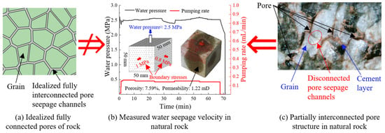
Classical seepage theories assume fully connected pores. But this assumption is not applicable to sandstone pores. Taking the physical test shown in Figure 1 as an example, if the pores in sandstone were fully connected, the seepage time for pore water to travel 25 mm to the rock sample surface under a pressure drop of about 2.5 MPa would be shorter than 0.01 s. This predicted time is far lower than the measured time of 68.05 min. Moreover, microscopic observation showed that the pores in sandstone are separated by the large mineral grains closely cemented (Figure 1), and are thus only partially connected. In fact, there are numerous isolated pore clusters in sandstone. Under such circumstances, regarding grain-scale pore water seepage in sandstone, permeability should not be represented by an average value; instead, the permeability field should be adopted to characterize the spatial variation in permeability in each volume element.
Figure 1.
An ideal fully interconnected pore model can hardly predict the seepage behavior of pore water in partially interconnected pores in natural rock.
Experimental tests have revealed that variations in fluid pressure within sandstone promote microcrack development and further induce permeability evolution [7]. However, the underlying mechanical mechanism of this phenomenon remains unclear. Furthermore, there is mesoscopic heterogeneity in permeability due to the permeability differences among different volume elements containing pores or grains. The micro-heterogeneity in permeability is crucial to the micro-flow characteristics in sandstone [8]. However, further investigation is needed to clarify the effect of pore water under the influence of permeability micro-heterogeneity on grain-scale HF propagation.
Meanwhile, the new seepage channels would update the permeability field and redistribute the grain-scale pore pressure. On the one hand, experimental observations showed that pre-existing pores can promote HF branching [9]. On the other hand, the strength at grain boundaries is weakened [10], and there exists grain-scale heterogeneity in tensile strength, which would facilitate continuous propagation of HF along mineral boundaries [10]. Both factors can allow HF to connect isolated pore clusters further, thus altering the grain-scale distribution of gradient pore pressure. However, the microcrack evolution and discontinuous propagation in regions far away from pre-existing continuous fractures under such updated gradient pore pressure have not yet been clarified.
Restricted by the characterization of stress fields and seepage fields, the physical experiments are incapable of further depicting the underlying mechanism in the process of grain-scale micro-crack formation and macroscopic HF growth under gradient pore pressure. Similarly, theoretical studies have focused on the critical conditions of microscopic HF formation and the influence of the fracture process zone on hydraulic fracture propagation [4,11], and the gradient pore pressure has been formulated as a body force instead of a traditional surface force [4]. However, the research scale was limited to a region approximately 1 mm directly ahead of a macroscopic HF, which is insufficient to depict the multi-fracture non-collinear propagation behavior as observed by X-ray Computed Tomography and micro-imaging techniques [12]. Additionally, it is challenging to obtain a stress-field solution under unconventional boundary conditions [13], hindering the application of such solutions to consider the problem of grain-scale crack growth and the influence of micro-heterogeneity in permeability and strength.
Notably, for the grain-scale crack evolution problem, numerical simulation provides a feasible solution. In numerical simulation, taking strength heterogeneity into account enables the simulation to better reproduce the physical reality of HF propagation [14]. The macro-scale anisotropic permeability was also considered [14,15]. However, the influence of the micro-heterogeneity in permeability on HF propagation has not been fully revealed. Fluid–solid coupling is an essential component in the numerical simulation of hydraulic fracture propagation behavior. The classical continuum Fluid–Structure Interaction (FSI) methodologies [16,17,18], including Arbitrary Lagrangian–Eulerian, Eulerian, immersed/embedded-interface, and partitioned formulations, treat both the fluid and the solid as continua where the interface is continuous. However, rock containing HFs is more akin to a discrete assembly of mineral grains and cement. Classical continuum FSI methodologies are not only computationally expensive but may also produce distorted results when applied to grain-scale hydraulic fracture evolution with non-prescribed crack paths. Among the proposed simulation methods for the study of grain-scale evolution of cracks during HF propagation, the combination of Computational Fluid Dynamics and Discrete Element Method (DEM) has potential advantages in terms of model establishment and fluid–solid coupling. Firstly, the true microstructure of rock could be more realistically simulated in numerical models, where the existing methods mainly include Delaunay triangulation (also called Voronoi tessellations), the centered axial method, and the maximal sphere method, etc. [15]. However, unlike magmatic rocks such as granite [19], sedimentary rocks such as sandstone possess distinct cement structure among larger mineral grains [8]. Meshes with mutually parallel boundaries created by Voronoi tessellation (even with boundary scaling like Figure 1a) deviate from the irregular shape of partially connected cement structure, hindering the simulation of permeability micro-heterogeneity. Secondly, for the fluid–solid coupling, the main methods include the pipe-domain method and coarse grid method. The corresponding fluid flow governing equations are usually solved by third-party codes such as FiPy and OpenFOAM [20,21], achieving relatively high accuracy. However, the force from the fluid was transferred to the solid by only the drag force under the assumption of fully connected porous media [15]. The fluid–solid force transfer principle needs to be improved to accommodate partially connected sandstone pore media. Cai et al. analyzed this force transfer principle between pore water and cemented minerals by pressure difference and viscous flow, which agreed well with the physical experiment [4] but has only been applied to theoretical models with simple boundary conditions rather than grain-scale numerical modeling.
Overall, for the question of crack grain-scale evolution during HF propagation in sandstone, there is a research gap in the mechanism by which gradient pore pressure affects grain-scale HF evolution in sandstone and the corresponding influence of mesoscopic heterogeneity in strength and permeability. To address this question, further improvements in sandstone meso-structure simulation and fluid–solid coupling methods are needed. This paper employs the K-means clustering algorithm to simulate the mesoscopic structure of sandstone and improve the force transfer principle in the fluid–solid coupling. The influence of mesoscopic heterogeneity in tensile strength and permeability on HF propagation is considered. The grain-scale evolution law of cracks is revealed. This research could deepen insight into HF propagation and facilitate advancement in reservoir stimulation technologies.
2. Methodology for the Numerical Analysis
2.1. Model Geometry and Parameter Calibration
The DEM is employed for the numerical analysis, and the Linear Parallel Bond Model is used to govern the mechanical behavior and determine the failure of particles in a 2D space. The DEM numerical model is established to simulate the structure of rock at the mineral grain scale. Taking sandstone as an example, the structure of sandstone could be characterized by the combination of large mineral grains and cement. Large mineral grains consist mainly of quartz. Pores are predominantly concentrated in the cemented layer and feature partial interconnection.
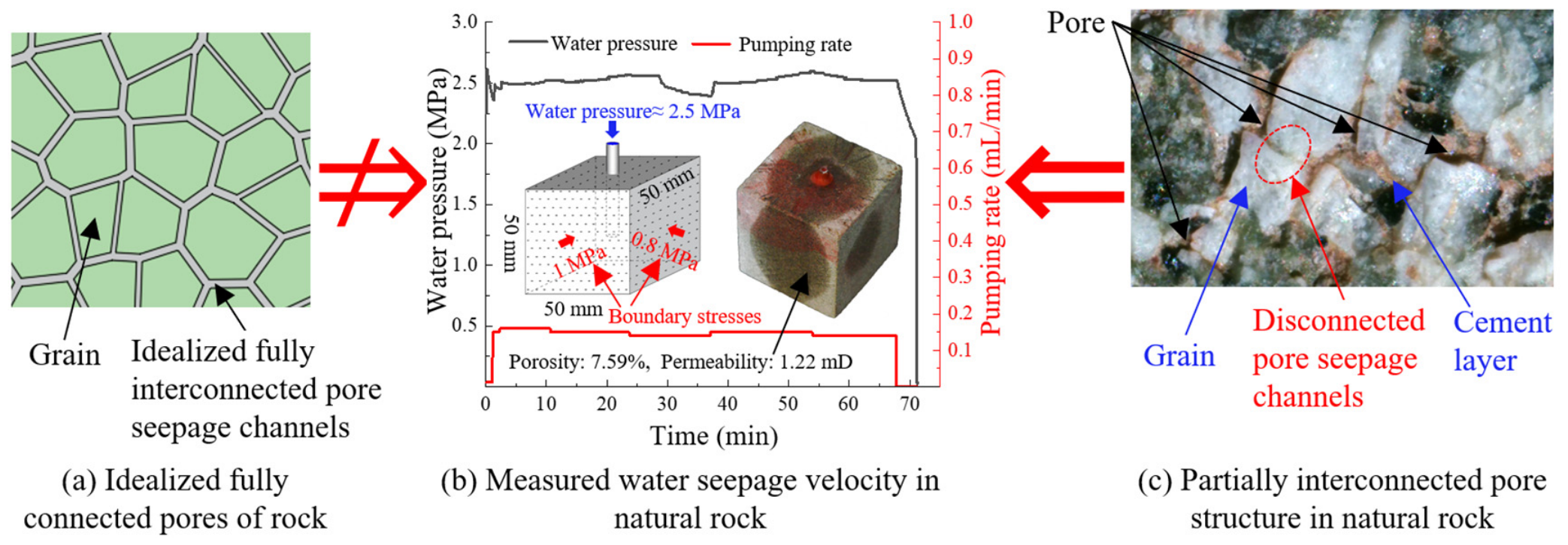
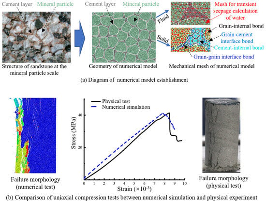
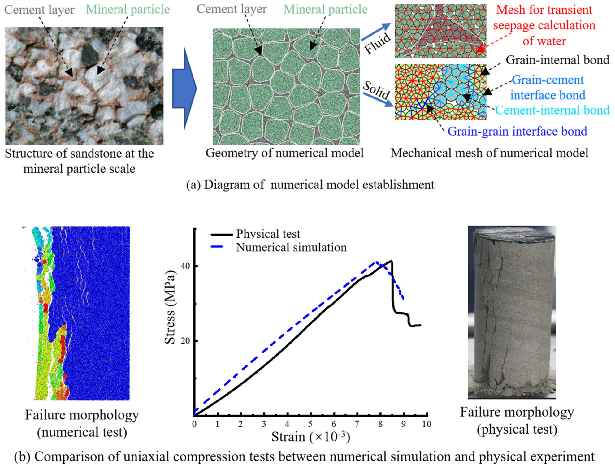
The partially connected pore structure of sandstone is constructed through mask-based screening of DEM particles. In detail, a sandstone meso-structure construction method based on the K-means clustering algorithm is employed (Figure 2). Firstly, points are randomly generated within the regions partitioned according to the mineral grain size. The K-means clustering algorithm and the convex hull algorithm are employed to generate closely spaced polygons with irregular boundaries according to these random points. Secondly, these closely spaced polygons were used as masks to select some particles inside the polygons as the large mineral grain group, while the remaining particles were classified into the cement layer group. In this way, there is no cement where the distance between polygons is smaller than the particle diameter, and vice versa, thereby creating the partially connected cement structure of sandstone. Finally, different initial porosities were assigned to the particles belonging to the large mineral grain group and the particles belonging to the cement layer group, simulating the permeability meso-heterogeneity of sandstone. It should be noted that the microstructure varies greatly among different rock types. In this study, the partially connected pore structure of sandstone is reconstructed to match the structure of a representative rock specimen adopted in the verification tests as closely as possible, as shown in Figure 2.
Figure 2.
Sandstone partially interconnected pore meso-structure construction method based on K-means clustering algorithm.
The larger grains and cement are assembled from multiple particles. There are grain-internal bonds and cement-internal bonds (Figure 3). For the strength at the boundaries, there are grain–grain interface bonds and grain–cement interface bonds. The mesoscopic parameters are respectively assigned to the numerical mineral grains and cement layers according to their contact type, simulating the strength meso-heterogeneity of sandstone (Figure 3a).
Figure 3.
Schematic of the numerical model establishment and calibration.
The mesoscopic parameters of the numerical model were determined to match the macroscopic parameters in the physical test. Macroscopic parameters were back-calculated from mesoscopic parameters via the trial-and-error approach, using uniaxial compression tests and uniaxial tensile tests in Particle Flow Code 6.0 (PFC 6.0). Then, the obtained macroscopic mechanical parameters were compared with physical test results in terms of mechanical parameters and failure morphology (Figure 2). Finally, the mesoscopic parameters corresponding to the macroscopic parameters that best matched the physical test values were adopted for numerical simulation.
In this paper, a set of mesoscopic parameters for homogeneous rock (Table 1) and another set for heterogeneous rock were prepared for subsequent analysis (Table 2). In detail, the homogeneous sample has a size of 50 mm × 100 mm, particle diameters ranging from 0.4 mm to 0.6 mm with a void ratio of 0.07, and contains 23,477 particles. The heterogeneous sample has a size of 10 mm × 20 mm, particle diameters ranging from 0.04 mm to 0.06 mm with a void ratio of 0.07, contains 93,648 particles, and the size of grains assembled by these particles ranges from 0.4 mm to 0.6 mm. In the heterogeneous sample, 82,356 particles constitute the grains, and the remaining particles form the cement layer. The density of particles is 2630 kg/m3.
Table 1.
Meso-macro mechanical parameters of homogeneous model.
Table 2.
Meso-macro mechanical parameters of heterogeneous model.
The grain–grain interface bond breakage is observed in the physical test to be the first failure mode in the surrounding rock at the HF tip (the picture is shown hereinafter). Then the weakest bond parameters were assigned to the grain–grain interface bond, which is also consistent with the existing study [10]. Interestingly, the tensile strength in the DEM-based model with the homogeneity assumption was usually higher than the physically measured values, as reported by Wang et al. [22]. However, as shown in Table 1 and Table 2, by further considering the tensile strength of weaker bonds in sandstone, the tensile strength of the numerical model can agree well with the physically measured values, which indicates that the established sandstone meso-structure achieves a more realistic simulation of rock mechanical behavior than conventional homogeneous models. Other parameters such as the elastic modulus in the model were kept identical.
In this study, mesoscopic parameters are calibrated according to the following criteria: specimens undergo pure tensile failure in uniaxial tensile tests, the macroscopic mechanical properties match the referenced experimental data, and the simulated failure morphology approximates the laboratory observations. All mesoscopic parameters are adjusted as shown in Table 1 and Table 2.
2.2. Governing Equations for Solid Deformation and Fluid Flow
Following the DEM [23], the solid motion/deformation is described by Newton’s second Law, and the bond breakage between particles is determined by the stress criterion, where the maximum tensile stress σt-max and the maximum shear stress σs-max are calculated as follows [22]:
where T is the normal force (N), M is the moment (N·m), and V is the shear force (N). According to beam theory, A is the area of the bond cross-section, I is the bond sectional moment of inertia, and R′ is the bond radius.
The fluid flow behavior is governed by the continuity equation for unsteady flow with sources, which is given by [24]:
where Φ0 is the effective porosity, ct denotes the total compressibility with ct = cΦ + cf, cf is defined as the compressibility of the fluid (MPa−1), and cΦ is defined as the pore compressibility of the rock formation (MPa−1). Φ0 ct represents the transient coefficient. K is the permeability (mD); μ is the viscosity of water (Pa·s); K/μ represents the diffusivity coefficient. q is the source term (s−1). The DEM solver adopted is PFC 6.0, in which the default force-balance criterion with a tolerance of 1 × 10−05 is used. The FVM solver used is FiPy running under Python 3.6.1. in which the LinearGMRESSolver is adopted, and convergence is achieved when the normalized residual falls below 5 × 10⁻⁸. To ensure one-to-one mapping of pore pressure information between DEM particles and FVM mesh cells, the FVM mesh cell edge length is set to approximately 1.8 times the DEM particle diameter, and a scheme is established to assign the external disturbance force to the particles covered by each mesh cell based on their area fractions. Therefore, for a given simulated rock meso-structure, both the DEM particle resolution and the FVM mesh resolution are nearly fixed in this study.
2.3. Fluid–Solid Coupling Method
2.3.1. Porosity and Permeability Evolution
Sandstone possesses internal pores. The porosity could be measured by Low-Field Nuclear Magnetic Resonance (NMR) with acceptable accuracy. However, poor connectivity between isolated pore clusters yields low macroscopic permeability. An artificial spherical porous medium is adopted for comparative explanation, and the corresponding permeability equation is given by [24]:
where C is the Kozeny constant, ranging from 0.5 to 0.6; L denotes the tortuosity of effective connected pores at rock interfaces, which takes values of approximately 2.2–2.4 for artificial porous media with uniform particle sizes; Σ represents the specific surface area, and (Σ=1.896/r0) can be adopted for randomly arranged artificial porous media, where r0 is the average particle radius of the rock.
For example, if the porosity of an artificial spherical porous medium reached 7.59% like the sandstone in Figure 1, the permeability should be 1000–2000 mD, as calculated by Equation (3). However, the permeability of this natural sandstone sample measured based on the Timur–Coates permeability model in the NMR test is only 1.22 mD. This indicates that pore connectivity is an essential factor for permeability. Hence, in this study, the connectivity coefficient is adopted to characterize the connectivity between isolated pores.
Firstly, the initial porosity φ0, connectivity coefficient β, and the initial permeability k0 are assigned to each particle. The grain-scale microcracking and HF would increase the connectivity, and the connectivity coefficient should be updated. When determining the permeability, the effective porosity φ is calculated as:
φ = βφ0
The permeabilities were calculated based on particle porosity and fracture aperture. In detail, using the Kozeny–Carman equation, the permeability kp contributed by pores is calculated according to the effective porosity φ of the particles within the mesh. The Kozeny–Carman equation is given in one of the following forms [25,26]:
where k0 is the initial permeability at the initial porosity φ0, and n and m are the porosity-sensitive exponents, with values of 3 and 2, respectively [27]. The permeability kf caused by the fracture aperture is calculated according to the Cubic Law:
where b is the aperture of HF (m). The mesh permeability k for transient seepage calculation is the sum of two permeabilities.
k = kp + kf
In this study, the initial porosity φ0 of all particles in the homogeneous sample is 0.0759. In the heterogeneous sample, the initial porosity φ0 is correlated with the particle number Ng and particle porosity φ0g of grains, as well as the particle number Nc and particle porosity φ0c of cement via the following equation:
Nanoscale pores develop within quartz during tectonic processes, fluid dissolution, and other diagenetic alterations. The grain porosity of quartz is measured in the range of 0.027–2.2% [28,29]. With reference to this range, the initial porosity of particles constituting large mineral grains is set to 1% as an example parameter in this study. Based on volume fractions, the initial porosity of particles in cement is 55.65%, which yields an overall initial porosity of 7.59%.
With an initial porosity of 7.59%, the connectivity coefficient should range from 0.07 to 0.08 to yield a permeability of 1.2 mD, as back-calculated via Equation (3). Hence, 99% of the particles have a connectivity coefficient of 0.08. Considering the existence of voids in sandstone, 1% of the particles are randomly assigned a connectivity coefficient of 1. The permeability of each mesh is updated according to the updated effective porosity and fracture aperture. For all particles, once bond-breaking events occur, the connectivity coefficient of the corresponding particle is updated to 1.
2.3.2. Solving Method for Seepage Field
Based on the finite volume method (FVM), FiPy is employed to solve the seepage field according to Equation (2), so that the pore water pressure can be obtained. The FiPy version is 3.4.5, which runs in the environment of Python 3.6.1. In detail, to obtain a relatively stable and accurate solution of the seepage field when the fracture permeability could be about 10 orders of magnitude higher than the matrix permeability, the LinearGMRESSolver of FiPy is customized and used. For transient marching termination, a dual-threshold strategy is adopted. Specifically, the simulation terminates when the pressure increment at the injection cell relative to its initial value exceeds a dynamic threshold, which is 1.0 MPa when the current pressure is below 9 MPa and 0.4 MPa otherwise. As a second strategy, the simulation also terminates when the relative change rate of the injection cell pressure between consecutive timesteps remains below 10% for 1000 consecutive steps, indicating a quasi-steady state. Decreasing the dynamic threshold can make the water-pressure curve more refined, but it also increases the computational time. The threshold adopted in this study is sufficient to capture the dynamically evolving water-pressure field during hydraulic fracturing.
For data exchange in the numerical simulation, before the FVM computation at each step, the porosity is updated according to the cracking events of particles and the permeability is recomputed. Then, the new permeability is transferred from the DEM solver to the FVM solver. The new seepage field is solved according to the updated permeability field.
2.3.3. Fluid–Solid Force Transfer Principles
An improvement to the fluid–solid force transfer principle is implemented for the case of seepage force in a partially connected porous medium. The fluid–solid coupling mechanism derived by Cai et al. [4] was employed in the numerical simulation, where the fluid, with a pore pressure difference Δpi (i = x, y), applied force on the solid porous structure in the form of normal force (Ft−i) and viscous force (Fw−s−i) on the scale of mineral particles. A detailed derivation can be found in Reference [4]. For the solid part of the pore structure in a unit volume for analysis, the coupled resultant force Ft−i − Ft−i+1 (normal pressure plus viscous force) is given by [4]:
where πR2 + S0 is the solid volume and pore volume in the original model [4].
Ft−i − Ft−i+1 = Δpi(πR2 + S0)
In this work, the disturbance force of the numerical model is generalized from Equation (8) to a more general form to facilitate numerical implementation. For a unit volume V with a pore pressure difference Δpi, the external disturbance force ΔF induced by the seepage exerted on the solid part in this unit volume is given by:
where S is the acting area of the force in unit volume V; the external disturbance force ΔF would locally break the equilibrium state of the solid structure, inducing local deformation and failure.
ΔF = ΔpiS
In the specific numerical implementation, each mesh is regarded as a unit volume to discretize the originally continuously distributed pore pressure. Owing to the continuity of meshes, force conservation could be preserved after discretization based on Equation (9). Within each mesh, the forces acting on the particles are positively correlated with the particle volume fraction. Theoretical analysis and experimental tests show that the crack propagation velocity in rock is much greater than the water seepage velocity measured in this study ([30,31] and Figure 1). When coupling the fluid seepage force with the particle skeleton force, the crack propagation rate is assumed to be much greater than the pore water seepage velocity. Accordingly, the solid phase is solved to a steady state at each seepage step, which enables complete crack evolution driven by the seepage field. In detail, after each step of FVM computation, the fluid seepage force data were exchanged to the DEM solver and then applied as external forces to the corresponding particles.
2.3.4. Fluid–Solid Coupling Procedure
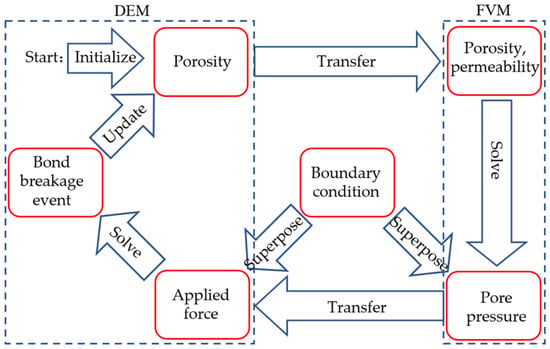
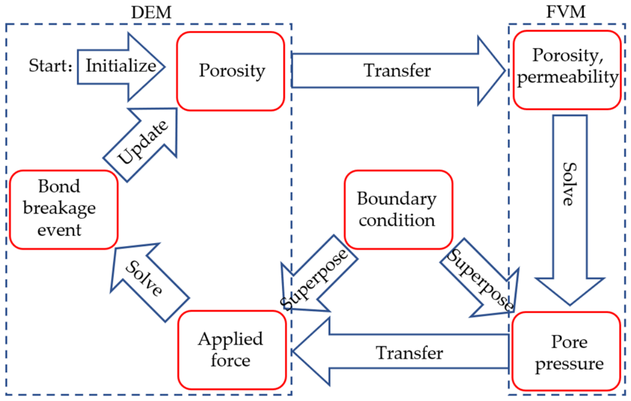
The FVM–DEM coupling procedure is implemented as a sequential explicit scheme (Figure 4). Firstly, each particle in the DEM model is assigned an initial porosity and connectivity coefficient (Equations (3) and (8)), and the effective porosity is calculated (Equation (4)). The effective porosity field is mapped from the DEM particles to the FVM cells, and the permeability is computed accordingly (Equations (5)–(7)). Then, considering the boundary conditions, the solution of pore pressure is obtained by FVM, as described in Section 2.3.2. The applied force is calculated according to Equation 10 and assigned to the particles in the DEM model. Finally, the DEM model is cycled under the applied force and boundary conditions to determine the bond breakage events. The porosity and connectivity coefficient are updated according to the bond breakage events using Equations (4)–(7), and the next coupling step begins.
Figure 4.
Schematic of the FVM–DEM coupling procedure.
During each coupling step, Python mainly serves as the coupling and workflow management layer, while the core numerical operations are executed by FiPy and PFC. Except for the force-transfer part, all computational kernels are accelerated by Numba JIT compilation with parallel loops. On a computer with an Intel (R) Core (TM) Ultra 7 265K CPU and 16 GB of RAM, the average time per coupling step in the case used in this study is about 0.8 h, and the memory usage is about 2 GB (including the memory overhead for data output and simulation monitoring).
2.4. Validation of the Numerical Model
To verify whether the rock micro-cracking during hydraulic fracturing could be captured by this numerical model, the model is validated theoretically and experimentally. There are numerous criteria for characterizing the critical water pressure during hydraulic fracture initiation and propagation based on various conceptual models assumed in existing studies, including but not limited to fracture initiation pressure, breakdown pressure, and fracture propagation pressure [32,33]. Uniquely, the propagation criterion of HF in rock based on the rock micro-cracking mechanism provided by Cai et al. [4] theoretically characterizes the critical water pressure required for mineral grain failure at the HF tip under a gradient pore pressure, which is named micro-cracking initiation pressure (MCIP), and it has been validated by physical laboratory tests. Owing to its satisfactory reliability and similar conceptual framework to the numerical model developed in this study, the MCIP model is adopted. MCIP is expressed as [4],
where ptip is the micro-cracking initiation pressure (MCIP) (MPa), py is the initial pore pressure (MPa), a/b is the mechanical shape factor, r0 is the average particle size (m), χ is the pressure diffusion coefficient (m2/s), t is the equivalent seepage time (s), σyy is the minimum principal stress (MPa), σxx is the maximum principal stress (MPa), and T is the tensile strength (MPa).
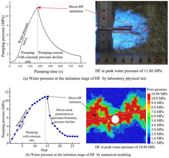
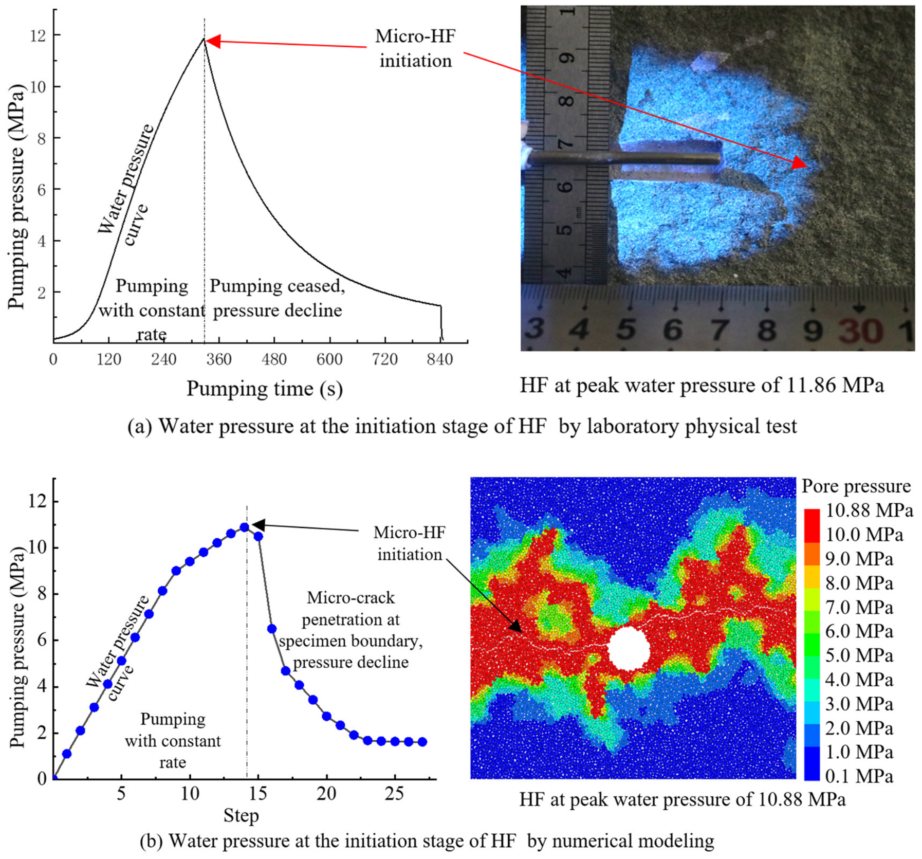
The parameters used are listed in Table 3. The theoretical MCIP was 11.4 MPa, and the water pressure at the HF initiation stage was measured to be approximately 11.86 MPa (Figure 5a) [4]. In the physical verification tests, pumping stopped after HF extended about 20 mm, leading to a post-peak leak-off process (Figure 5a). The measured pressure is approximately regarded as the water pressure at the HF initiation stage. It should be noted that this peak value is achieved by controllable fracturing, which differs from conventional breakdown pressure. In this study, a similar measuring approach is adopted. A rectangular numerical specimen with dimensions of 10 mm × 40 mm, containing 186323 particles, is constructed. The maximum principal stress σxx is horizontally applied along the long axis of the specimen, and the minimum principal stress σyy is vertically applied along its short axis. When the water pressure rose to 10.88 MPa, a macroscopic HF approximately 2.5 mm in length initiated at the borehole (Figure 5b). Then, the microcrack propagated to the specimen surface, and the pressure began to decline (Figure 5b). Hence, in the numerical simulation results, the water pressure at the HF initiation stage was approximately measured to be 10.88 MPa, yielding a relative error of 4.56% compared with the theoretical value and 8.26% compared with the physical test result. Verified against theoretical benchmarks and physical experimental benchmarks, the numerical model proposed in this paper can satisfactorily simulate the rock micro-cracking behavior of sandstone under a gradient pore water pressure.
Table 3.
Example parameters for validation.
Figure 5.
Verification of the numerical model by water pressure at the HF initiation stage. (Note: Experimental data in (a) are from reference [4]).
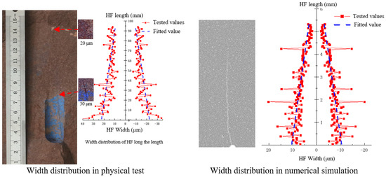
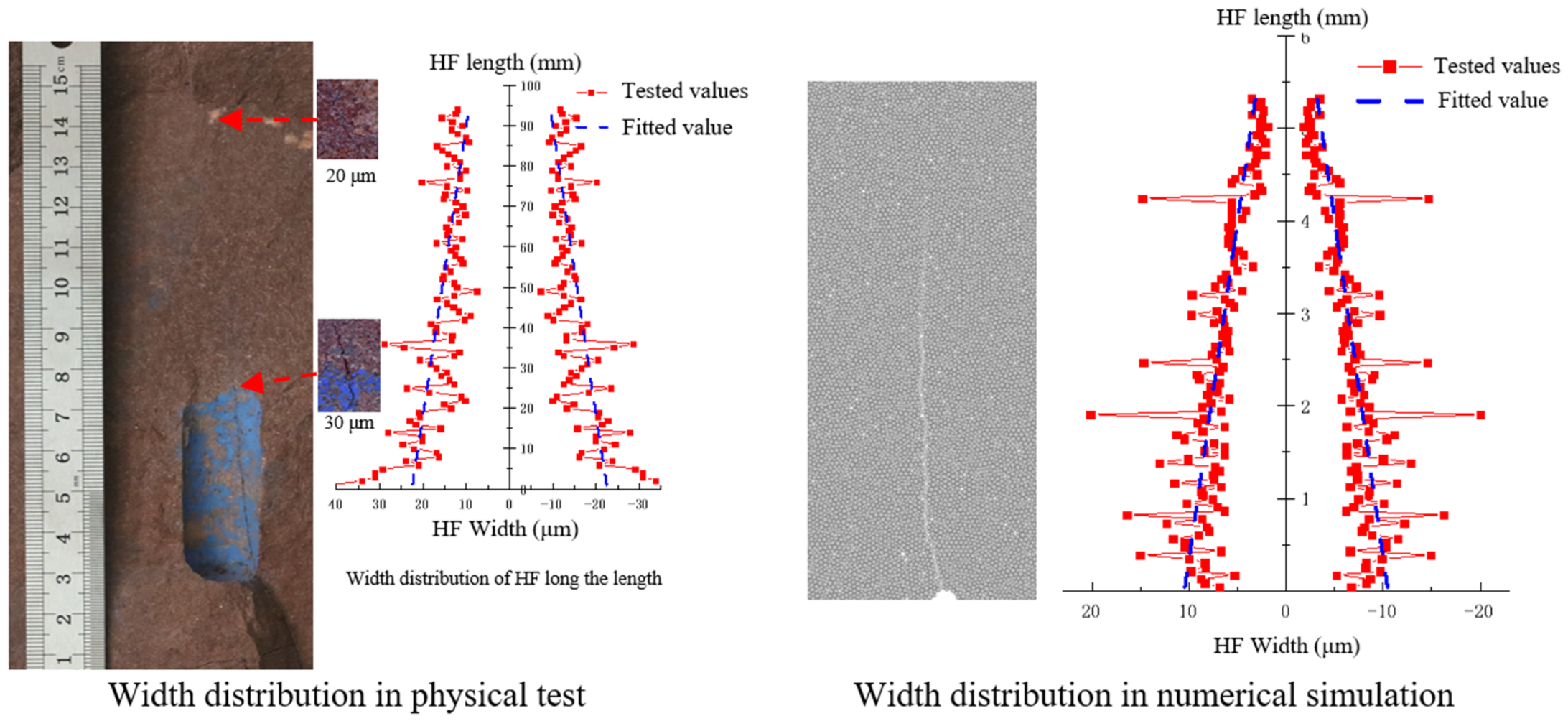
In addition, the numerical model was validated in terms of HF width distribution characteristics. A previous study [4], by analyzing HF aperture data measured in engineering-scale hydraulic fracturing and laboratory hydraulic fracturing (where the aperture was observed using microscopy and embedded fiber Bragg gratings), indicated that the ratio of HF length to width falls within the range of 103–104 and that the measured grain-scale HF apertures exhibit a linear distribution [4]. In this study, the parameters in Table 3 and Table 1 were used. To achieve a balance between the fine characterization of HF aperture and the computational efficiency, a 20 mm × 10 mm homogeneous model is used. As shown in Figure 6, the HF width also exhibits approximately linear distribution characteristics along the HF length in the numerical model. The geometric length-to-width ratio of HF is about 0.8 × 10³, which is of the same order of magnitude as the physically measured value of 4.5 × 10³. The discrepancy arises not only from differences in parameters such as rock permeability and elastic modulus, but also from the fact that the width in the numerical simulation is measured under pore water pressure; this value is larger than the width measured in the laboratory after the water pressure is released. The existing HF width theory (such as classical KGD-type HF width theory [34]), derived from Sneddon’s solution [35], predicts a length-to-width ratio about two orders of magnitude lower than the measured values in the laboratory, which can be verified by experimental data reported. Since this study uses the measured data as the benchmark, no further comparison with the related theory is conducted. Therefore, in terms of the HF width distribution characteristics and the orders of magnitude of the corresponding characteristic parameters, the proposed model can satisfactorily simulate rock deformation under a pore pressure gradient.
Figure 6.
Comparison of HF width distribution characteristics between numerical model and physical experiment [4].
3. Mechanism of Hydraulic Fracture Propagation Under Pore Water Pressure Disturbance
Rock is a porous medium. Pore water flows through rock during hydraulic fracturing. Disturbance of pore water pressure breaks the stress equilibrium of minerals and induces local deformation and cracking. This section discusses this process based on numerical models with a homogeneity assumption for single-factor analysis.
3.1. Numerical Simulation Scheme
To eliminate interference, the homogeneous porous medium assumption is adopted in this section. Meanwhile, one mineral grain is represented by one particle. Hence, the particle radius is 0.2–0.3 mm. The sample size is 100 mm in length and 100 mm in width. For single-factor analysis, the strength and permeability of both large mineral grains and cement are set to be identical in this section. The meso-macro mechanical parameters of the numerical model are shown in Table 1. The pumping rate was 2 mL/min. The outer boundary stresses were 16 MPa in the horizontal direction and 8 MPa in the vertical direction. The outer boundary pore pressure was 0.1 MPa.
3.2. Disturbance Effect of Pore Water Pressure with Gradient
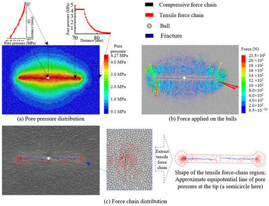
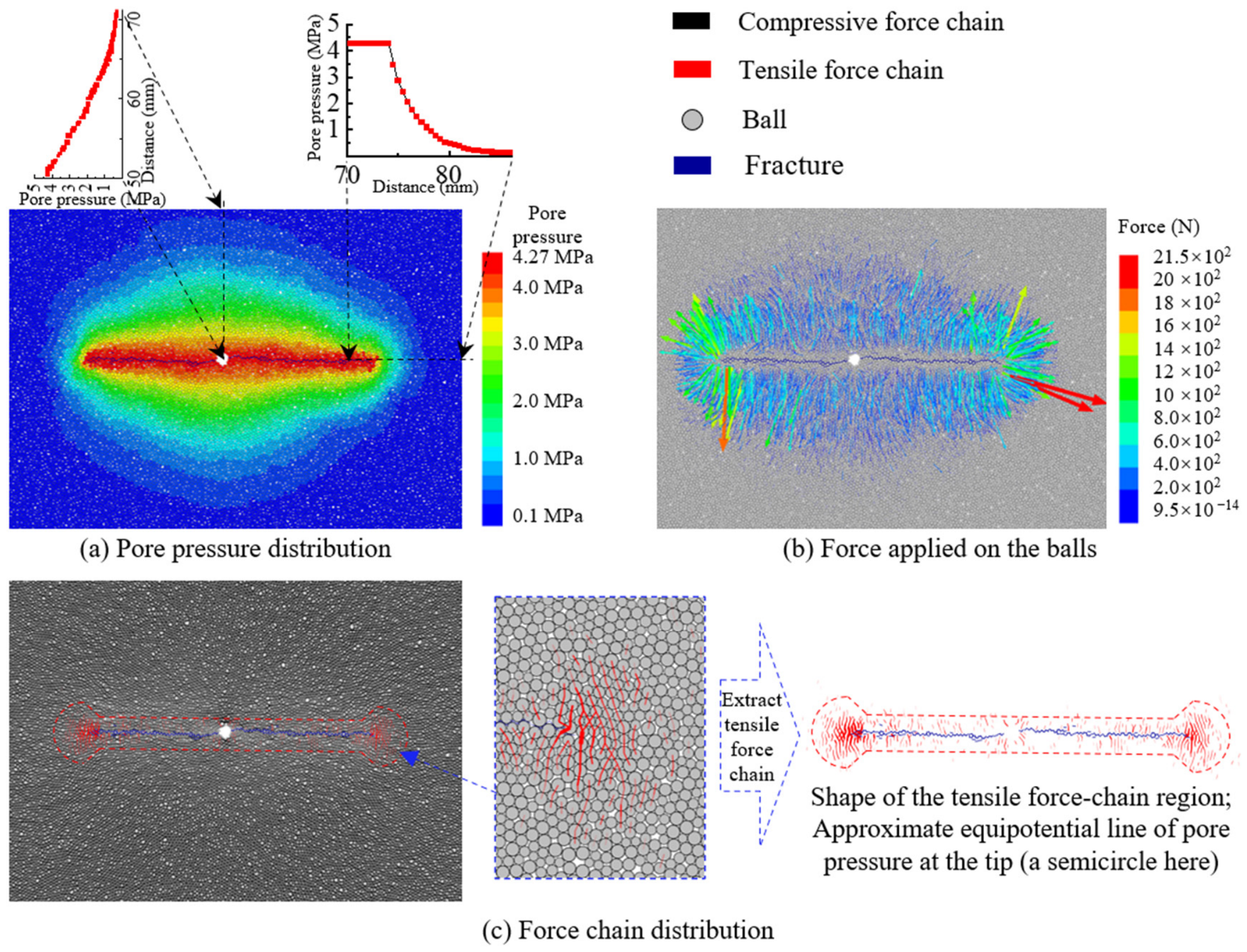
The disturbance of pore water pressure comes from its non-uniform distribution (Figure 7a). Further, the distribution of the pore water pressure is jointly affected by propagated fracture and seepage time. As exemplified in Figure 7, in the region near the borehole, there is a relatively longer seepage duration and seepage distance, resulting in a lower pore pressure gradient. Conversely, in the region near the HF tip, there was a relatively shorter seepage duration and seepage distance, resulting in a higher pore pressure gradient. Thus, there were spindle-shaped equipotential lines of pore water pressure. For a mineral particle, the force applied (Equation (10)) is positively correlated with the pore pressure gradient. Caused by the gradient distribution feature of pore water pressure, the forces applied on mineral particles exhibited a smaller magnitude and wider affected area near the borehole, but a larger magnitude and narrower affected area at the tip (Figure 7b).
Figure 7.
Distributions of pore water pressure, disturbed force applied to the particles, and contact force during HF propagation.
The force applied to mineral particles disturbs the initial stress equilibrium, and the compressive contact force is changed into a tensile contact force locally (Figure 7c). The directions of tensile forces among grains are perpendicular to the minimum principal stress. Furthermore, the spindle-shaped distribution of the pore water pressure leads to stress concentration at the tip, and a tensile force-chain zone is preferentially formed at the tip. According to the numerical modeling results based on DEM, the shape of the tensile force-chain zone at the tip approximately coincides with the pore water pressure equipotential lines. For example, the tensile force-chain zone at the tip is approximately semicircular in Figure 7c. Further, it could be observed that the maximum tensile force appears at the tip of microscopic HF (Figure 7c), which agrees with the theoretical analysis results derived by Cai et al. [4].
3.3. Crack Evolution During Hydraulic Fracture Propagation in Cemented Porous Media
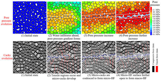
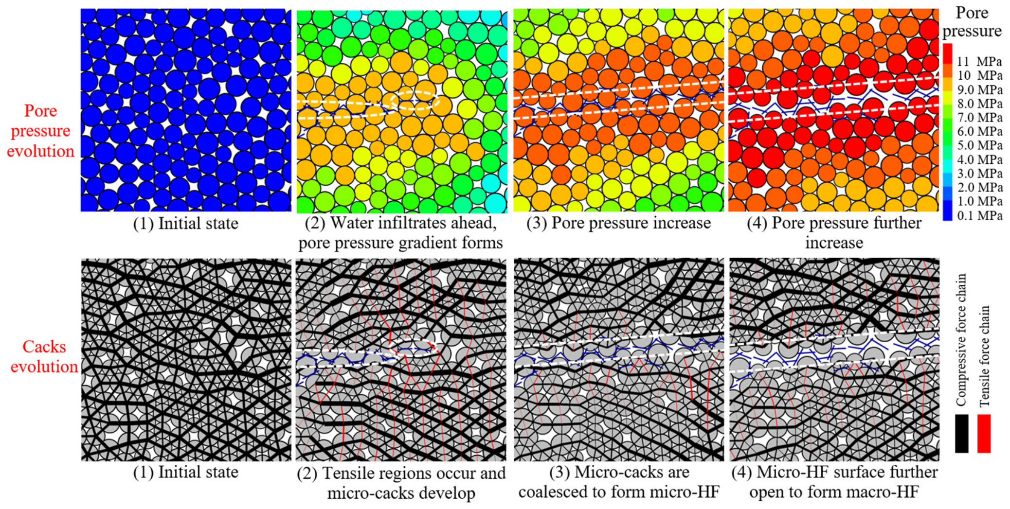
Under the disturbance of gradient pore water pressure, the bonds between mineral particles broke, leading to a multi-scale evolution of cracks to form macroscopic HF (Figure 8). At the first stage, under the action of both the in situ stress and the initial pore pressure, rock mineral particles in equilibrium bear compressive contact forces. At the second stage, as fracturing was conducted, a pore pressure gradient formed, and the states of contact forces between rock mineral particles were locally transformed from compression to tension to form the tensile force-chain region. In the tensile force-chain region, tensile failure would occur if the mesoscopic tensile stress between grains exceeded the mesoscopic tensile strength, forming micro-cracks. At the third stage, with a further increase in water pressure, the residual bonds of mineral particles between the micro-cracks and the microscopic HF surface broke, resulting in the propagation of the microscopic HF. At the final stage, with the further increase in water pressure, the microscopic HF opened, forming macroscopic HF. The crack characteristics at each evolution stage agree well with the physical experiment results observed [4].
Figure 8.
Evolution of pore water pressure and cracks during HF propagation.
4. Crack Evolution at the Tip During Hydraulic Fracturing for Sandstone Considering Micro-Heterogeneity in Tensile Strength and Permeability
In addition to the disturbance effect of the pore water pressure gradient, the micro-heterogeneity in tensile strength and permeability is another governing factor in HF propagation in hydraulic fracturing of natural sandstone. In detail, under the same stress conditions, bonds with lower tensile strength would break preferentially. On this basis, the micro-heterogeneity of permeability would control the distribution of weak-bond failure and further influence the pore water pressure distribution and its disturbance. In this section, the simulation of this micro-heterogeneity would be performed, and the crack evolution at the tip during hydraulic fracturing for sandstone would be discussed.
4.1. Numerical Simulation Scheme of Micro-Heterogeneity in Tensile Strength and Permeability
As introduced in Section 2, the heterogeneous sample is adopted for numerical simulation. The large mineral grains and the partially connected cement structure of sandstone are created based on the K-means clustering algorithm and the convex hull algorithm.
To simulate the micro-heterogeneity in tensile strength and permeability, the mesoscopic parameters are assigned to the mineral grains and cement according to their contact types, respectively. The detailed parameters are shown in Table 2. The micro-heterogeneity in permeability is achieved by setting different porosity and initial permeability as introduced in Section 2.3.
4.2. Characteristics of Pore Pressure Disturbance Under the Influence of Permeability Micro-Heterogeneity
Sedimentary processes render the pores of sandstone partially connected, resulting in numerous fully enclosed or semi-enclosed isolated pore clusters. For convenience of description, these isolated pore clusters are termed pore subdomains, and the aggregate of all subdomains is defined as the pore parent domain.
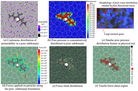
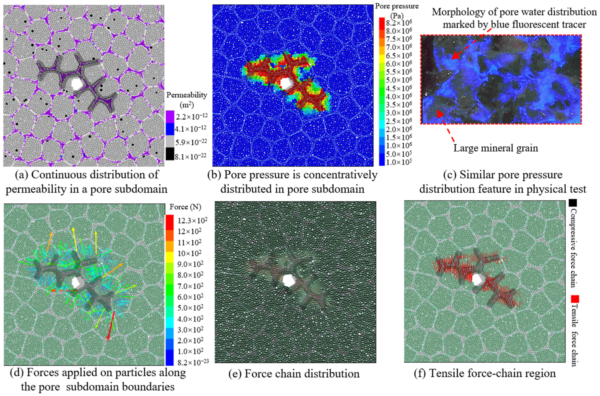
A pore subdomain linked with the borehole is taken as an example to discuss the characteristics of pore pressure disturbance under the influence of permeability micro-heterogeneity (Figure 9). In a single pore subdomain, the permeability values among neighboring volume units exhibited spatial continuity and almost no sudden mutation (Figure 9a). Once connected with boreholes or HF, high pore pressure occurred within the pore subdomain (Figure 9b). Notably, influenced by the irregular geometry of the pore subdomain, the mesoscopic distribution of pore water pressure exhibited non-collinear characteristics. A similar pore water pressure distribution morphology was also observed in the physical experiment at the grain scale [4] (Figure 9c). Then, the forces caused by the pore water pressure are applied on particles along the convex boundaries of the pore subdomain. The boundary of a pore subdomain was the tip of the seepage field, where the applied fluid force was relatively large (Figure 9d). In the area covered by the pore subdomain, the stress state between particles changed from compression to tension, forming a tensile stress region (Figure 9e, f). Different from the case of the homogeneous medium (Figure 7c), when the strike of pore water pressure (the direction of peak pore pressure distribution) deviated from the minimum principal stress, the tensile stress direction also deflected toward the strike of pore water pressure (Figure 9f). Consequently, under the influence of permeability micro-heterogeneity, the tensile stress region induced by pore water pressure disturbance exhibited non-collinear and deflected distribution features.
Figure 9.
Disturbance effect of pore water pressure in a single pore subdomain. (Note: Experimental data in (c) are reproduced from reference [4]).
4.3. Multi-Scale Evolution of Cracks During Hydraulic Fracture Propagation in Sandstone
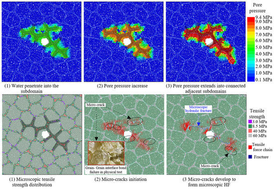
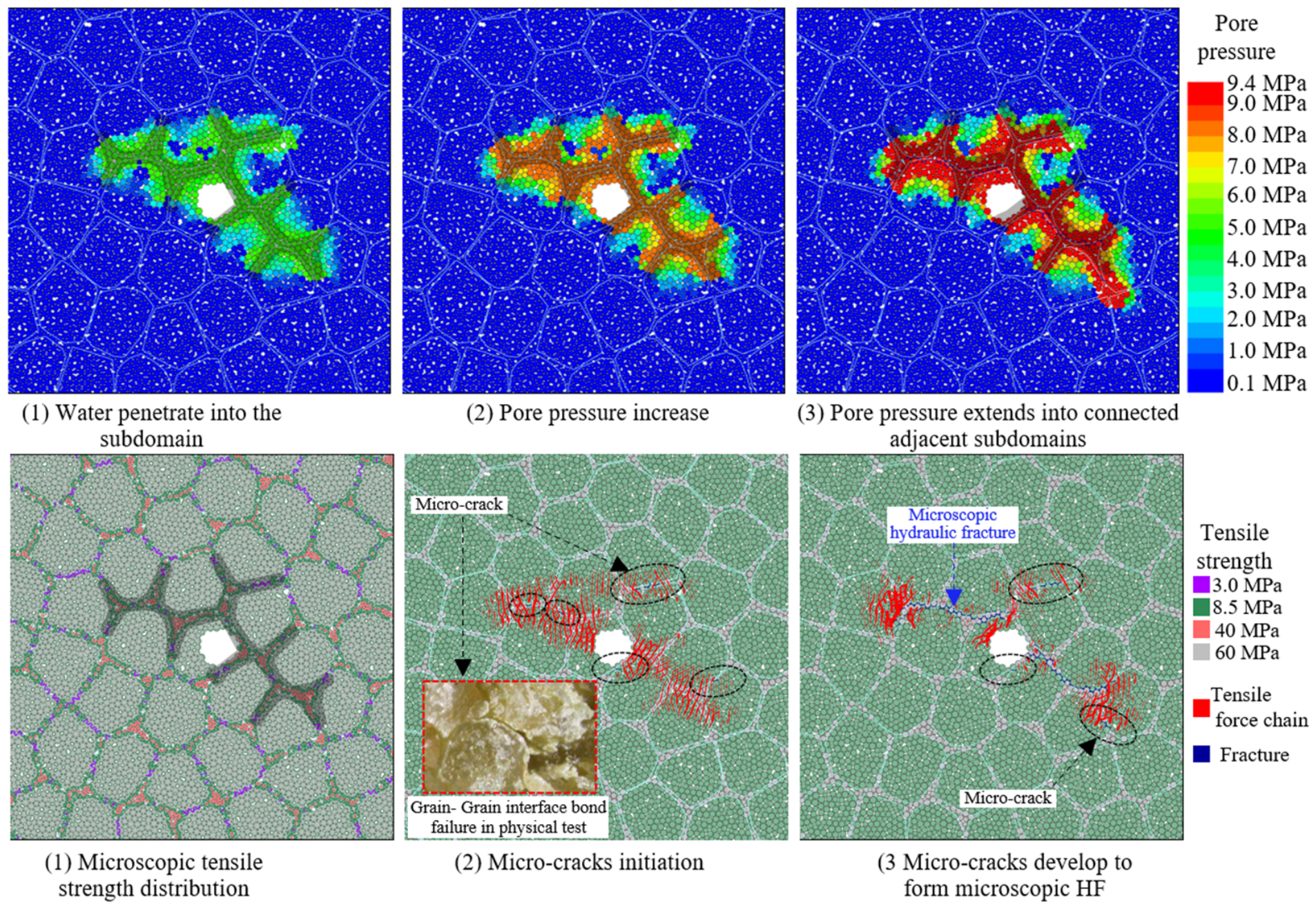
With increasing pore water pressure, the disturbance is enhanced, and the tensile stress among grains rises. Microscopic weak planes among mineral particles and cements fail preferentially, resulting in micro-crack initiation. Grain–grain interface bonds with a microscopic tensile strength of 3 MPa were the weakest in the numerical model of Figure 10 and failed preferentially. In detail, bonds oriented more perpendicular to the minimum principal stress failed earlier, as revealed by Equation (11). The micro-cracks initiated owing to the weak bond failure. However, within the tensile force-chain region that exhibited non-collinear and deflected distribution features, weaker bonds were discretely distributed, leading to the non-collinear and discrete distribution features of micro-cracks (Figure 10). With a further increase in pore pressure in the pore subdomain, adjacent micro-cracks coalesced to form microscopic HF. Interestingly, widely spaced micro-crack clusters tended to form multiple non-collinear microscopic HFs along the minimum principal stress direction, rather than a single fracture as in the case of a homogeneous medium.
Figure 10.
Pore pressure and crack evolution in a single pore subdomain.
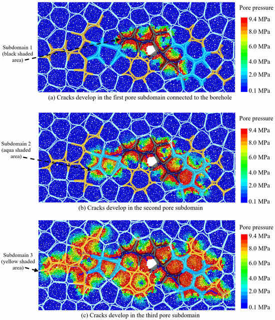
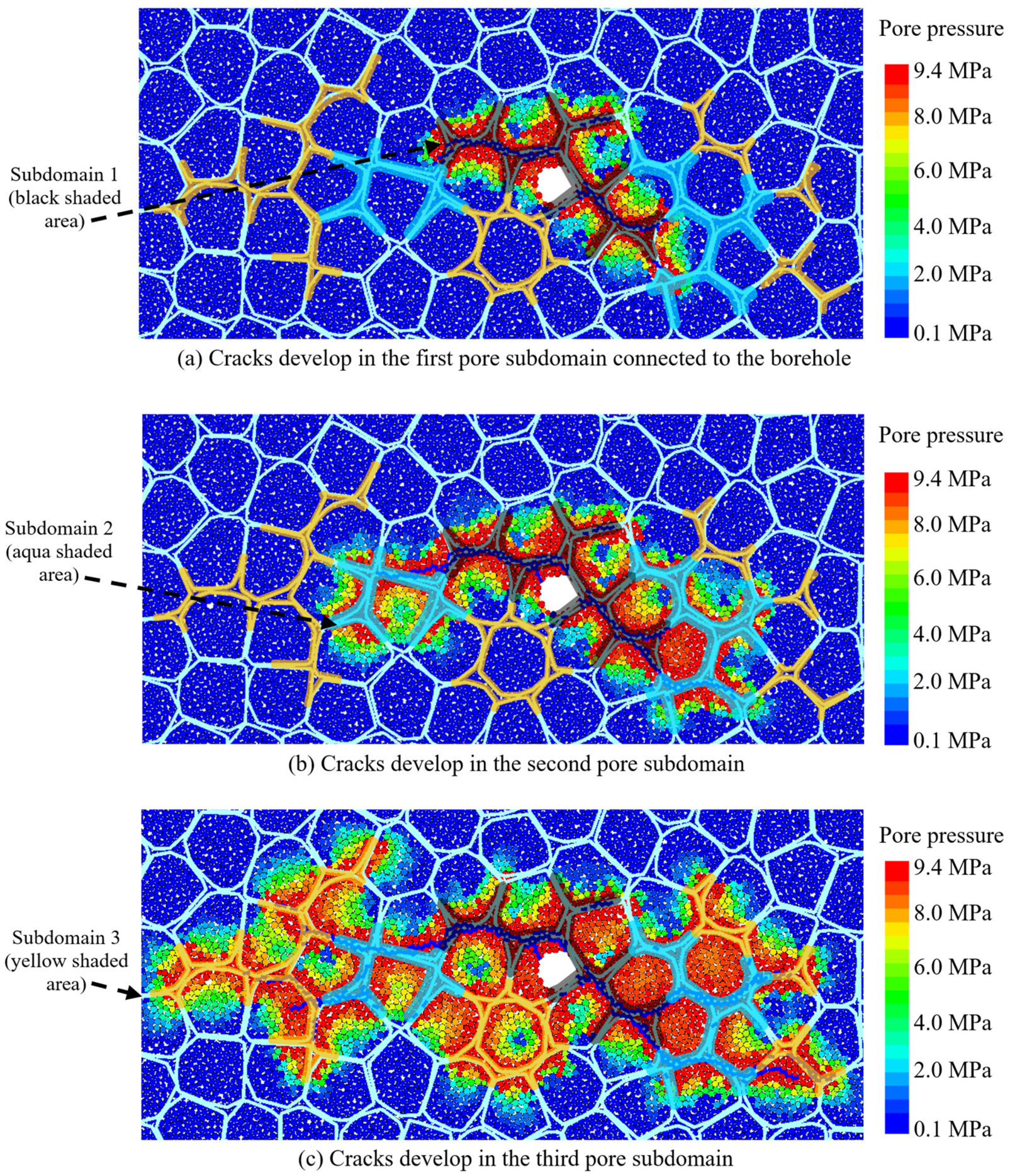
Moreover, such crack evolution was not restricted to one individual subdomain, but occurred progressively in different adjacent pore subdomains. Given the low permeability of large mineral grains, particle-particle interface bonds commonly exist at the boundaries of adjacent subdomains. Interestingly, the pore subdomain boundaries are the tips of the seepage field (Figure 9d), where the pore pressure gradient is high and stress concentrates, readily triggering the initiation of microcracks. The micro-crack initiation at the subdomain boundary improves the permeability and creates seepage channels between different pore subdomains, leading to similar crack evolution repeats. As shown in Figure 11, there were three sets of adjacent subdomains as an example. Firstly, Subdomain 1 was initially linked to the borehole, where water pressure increased. The process of micro-crack initiation and microscopic HF growth took place (Figure 11a). When the micro-cracks reached the boundary of Subdomain 1, Subdomain 2 was linked with Subdomain 1 by the micro-cracks, allowing pore water to flow into Subdomain 2 (Figure 11b). Then, a similar process of microcrack initiation and microscopic HF growth repeated in Subdomain 2 and made Subdomain 2 connected with Subdomain 3. Finally, micro-cracks and microscopic HF developed in Subdomain 3, and other subdomains were further connected, allowing the micro-cracks and microscopic HF development in a wider range (Figure 11c).
Figure 11.
Crack evolution in different pore subdomains.
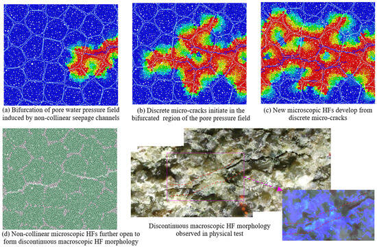
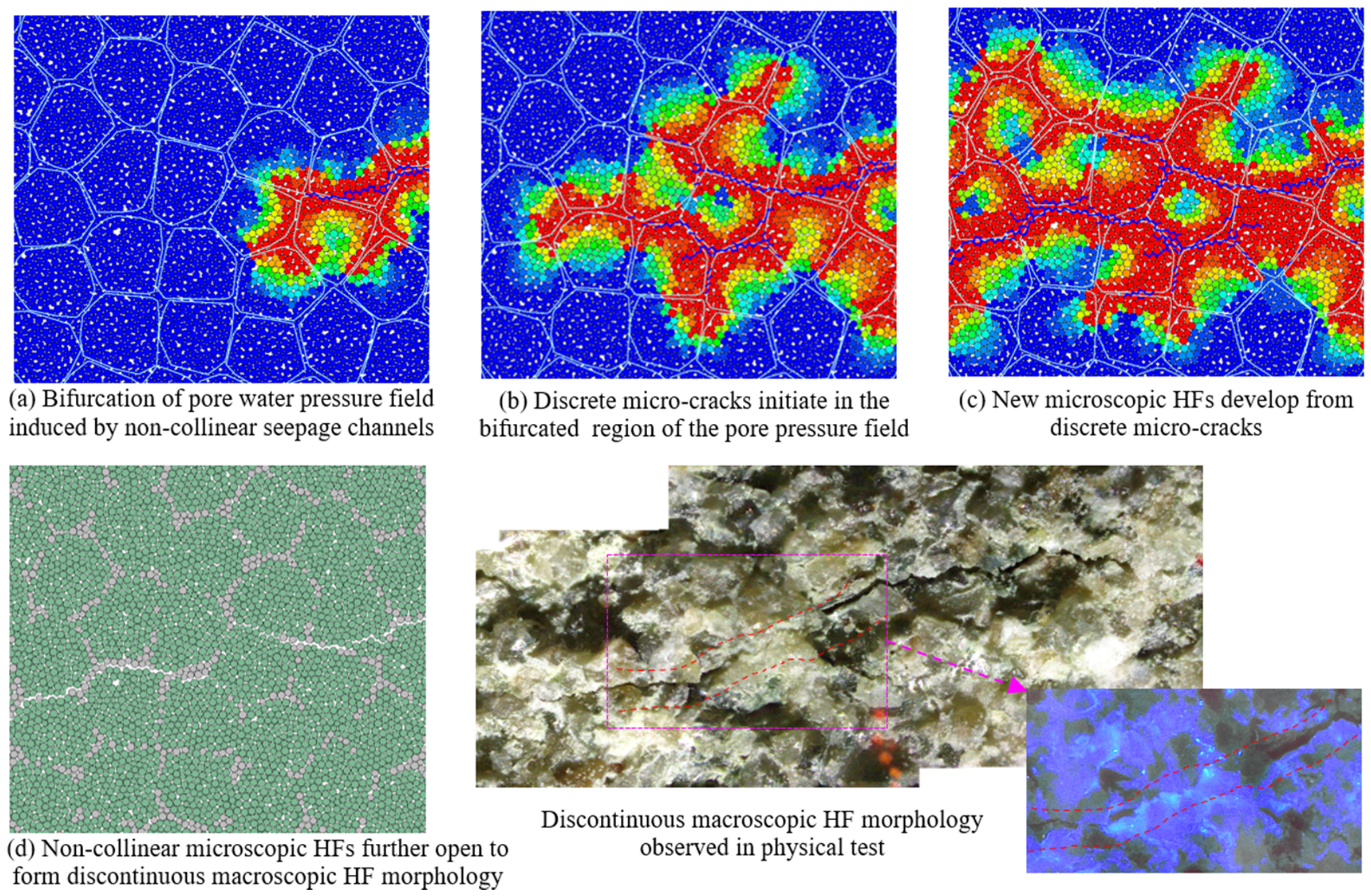
As crack evolution occurs progressively across various pore subdomains, discontinuous, non-collinear microcracks and microscopic HFs form in the region disturbed by pore water pressure. As a result, in view of the entire pore parent domain, macroscopic HFs present complex propagation morphology such as discontinuous extension and deflection. As exemplified in Figure 12, influenced by the permeability micro-heterogeneity, there were seepage channels non-collinear with the macroscopic HF, leading to the bifurcation of the pore water pressure field (Figure 12a). Influenced by the tensile strength micro-heterogeneity, discrete micro-cracks initiated in the bifurcated region of the pore pressure field (Figure 12b). New microscopic HFs developed from discrete micro-cracks exhibiting a non-collinear distribution characteristic (Figure 12c). With the further opening of microscopic HFs, adjacent non-collinear microscopic HFs coalesced, resulting in the deflected and discontinuous propagation morphology of macroscopic HF (Figure 12d), as observed in the physical experiments [4]. This study newly identifies the phenomenon that discontinuously initiating microcracks connect pore clusters to form connected seepage channels, which differs from the conventional understanding that continuously propagating hydraulic fractures create flow pathways for fluid.
Figure 12.
Discontinuous propagation of HF dominated by mesoscopic heterogeneity. (Note: Experimental data are reproduced from reference [4]).
The disturbance effect of gradient pore water pressure serves as the direct controlling factor for HF propagation. Combined with the influence of mesoscopic heterogeneity in tensile strength and permeability, in regions away from pre-existing flaws, HF could initiate and propagate due to the influence of the gradient pore pressure field. This behavior is different from the traditional understanding of HF propagation based on linear elastic fracture mechanics.
5. Discussion and Prospect
In this paper, by proposing a sandstone meso-structure construction method based on the K-means clustering algorithm, the meso-heterogeneity in tensile strength and permeability of sandstone was simulated. The fluid–solid force transfer principle in fluid–solid coupling was improved. The numerical model was validated by physical test results. HF propagation mechanism driven by the disturbance effect of gradient pore water pressure was revealed. The crack evolution law at the tip during hydraulic fracturing for sandstone was depicted.
5.1. Limitation of This Study
During the DEM-based numerical simulation, it was found that the same macroscopic performance could be almost achieved by multiple combinations of mesoscopic parameters. This limitation of parameter non-uniqueness in the DEM model has long remained unresolved [22], but its effect on this research is within an acceptable range. Even rocks of identical lithology exhibit slight disparities in physical and mechanical parameters within acceptable ranges [36]. Furthermore, this study focuses on the grain-scale disturbance induced by gradient pore water pressure, and only requires one set of reasonably calibrated illustrative parameters. Therefore, adopting reasonable illustrative parameters derived from natural rock does not hinder the exploration of the basic evolution law of grain-scale cracks subjected to gradient pore water pressure disturbance. Accordingly, some subordinate factors were moderately simplified.
The tensile strength was the key factor in HF propagation in rock. It was found that the variation in elastic modulus had little influence on the tensile strength in a uniaxial tensile test. Hence, the elastic modulus was simplified in this study. Moreover, the simplified geological conceptual model based on the sandstone meso-structure characteristics was used; future studies may focus on the influence of specific mineral types. Similarly, the bond failure modes were not distinguished, mainly due to the lack of physical experimental evidence at the mesoscopic scale. In this study, the macroscopic mechanical parameters were the benchmark. Based on the meso-macro mechanical parameters used, there were tensile failures for the case of HF propagation in homogeneous porous media (for example, models in Section 3) and tensile-shear mixed failures in mesoscopic heterogeneous porous media (for example, models in Section 4). The shear failures mainly occurred in some bond-breaking events when the HF deflected.
Meanwhile, the Kozeny–Carman equation adopted in this study is a semi-empirical method for permeability prediction, where the partial connectivity of pores is not considered [24]. Although the Kozeny–Carman equation is sufficient to characterize the variation in matrix permeability during crack evolution in numerical modeling, this study reveals that grain-scale crack evolution could enhance the pore connectivity. To further improve prediction accuracy, future work could consider this pore-linking principle to optimize existing permeability evaluation models. Admittedly, the two-dimensional numerical simulation results in this study merely elaborate the basic mechanism that microcracks create seepage channels connecting isolated pore clusters. The spatial range of these seepage networks in three dimensions and their permeability-improving effects remain to be quantitatively investigated in three dimensions.
5.2. Strengths of This Study
A sandstone meso-structure construction method based on the K-means clustering algorithm was used. Compared with existing methods such as the method based on Voronoi tessellation (Figure 1a), the proposed method could more reasonably reproduce the meso-structure of partially connected cement in sandstone, achieving the simulation of meso-heterogeneity in tensile strength and permeability.
Owing to the disturbance effect of pore water pressure with a gradient, the pore pressure distribution is vital for the grain-scale crack evolution. The pore pressure distribution is controlled by permeability. Previous studies considered the influence of permeability anisotropy on macroscopic seepage. In contrast, this study focuses on the permeability meso-heterogeneity at grain-scale as well as its dynamic evolution induced by microcrack growth. The new findings revealed that permeability meso-heterogeneity plays a key role in the initiation and propagation of mesoscopic HFs. Conventionally, HFs should initiate from pre-existing flaws such as fractures or boreholes. However, this study showed that, after the evolution of the pore pressure field, HFs could initiate and propagate in other regions far away from pre-existing fractures covered by the gradient pore water pressure, extending the understanding of HF propagation mechanisms.
The controllable hydraulic fracturing experiments have confirmed that the water pressure would continue to rise after HF initiation [4], yet the underlying mechanism remains unclear. By considering the meso-heterogeneity in tensile strength, it was found that HF would initiate at relatively low water pressure when the weaker bonds break, whereas higher water pressure is required for continuous propagation through areas with stronger bonds; the increase in water pressure is caused by the meso-heterogeneity. This finding helps reduce the prediction error of HF propagation distance.
5.3. Significance of This Study
Traditional linear elastic fracture mechanics based on the homogeneous medium assumption is incapable of explaining non-collinear and discontinuous HF propagation behavior. Although the influence of pre-existing fractures is considered, the source of these prefabricated fractures is ambiguous, making these findings difficult to apply at the mineral particle scale. By considering the meso-heterogeneity in tensile strength and permeability, this study provided new insight into the micro-crack initiation and HF propagation based on the grain-scale weaker plane failure under the disturbance of pore water pressure, advancing the scientific cognition of non-collinear and discontinuous HF propagation behavior.
Conventional reservoir stimulation technologies enhance the fracture permeability of the reservoir by creating HF. This study revealed that the linking behavior between different irregular pore subdomains induced by micro-crack growth could transform locally connected pores into nearly fully connected ones, without relying on the existence of HFs. This finding could inspire a new reservoir stimulation idea oriented to enhance matrix permeability by constructing microcrack-based seepage channels. This represents an important technological advancement for geo-resource development relying on matrix pores, such as in situ leaching of sandstone-type uranium deposits. It provides a theoretical foundation for the technological progress of refined reservoir permeability enhancement.
6. Conclusions
In order to reveal the grain-scale evolution law of cracks during HF propagation in sandstone, the sandstone meso-structure construction method based on the K-means clustering algorithm is proposed to simulate the mineral particles and the structure of partially connected cement. The fluid–solid force transfer principle in fluid–solid coupling is improved by simultaneously considering the normal force and viscous force of the fluid. The disturbance effect of pore water pressure gradient and the influence of meso-heterogeneity in tensile strength and permeability on HF propagation are studied. The main conclusions are as follows:
- In the region covered by a gradient pore water pressure, the fluid forces applied on mineral particles are positively correlated with the pore pressure gradient and change the stress state among mineral particles from compression to tension. The shape of the tensile force-chain region at the HF tip approximately coincides with the pore water pressure equipotential lines. The continuous intensified disturbance of the gradient pore water pressure serves as the dominant factor controlling the initiation and coalescence of grain-scale microcracks within the tensile force-chain region, the formation of microscopic HFs, and final opening into macroscopic HFs.
- Influenced by the grain-scale meso-heterogeneity in permeability, isolated pore clusters partially connected with HFs become seepage channels non-collinear with HFs, leading to the bifurcation of the pore water pressure field. Influenced by the meso-heterogeneity in tensile strength, discrete micro-cracks initiate in the region disturbed by gradient pore water pressure. New microscopic HFs develop from discrete micro-cracks and exhibit non-collinear distribution characteristics. Adjacent non-collinear microscopic HFs coalesce, resulting in the deflected and discontinuous propagation morphology of macroscopic HFs.
- The grain–grain interface bonds with lower tensile strength are the boundaries of initially isolated pore clusters, which are also the tips of the seepage field during fracturing and undergo intense disturbance of the gradient pore water pressure. Micro-cracks tend to initiate at the boundaries of initially isolated pore clusters and serve as seepage channels between adjacent pore clusters, thereby enhancing connectivity. Under such a connectivity enhancement mechanism, the pore pressure field continuously extends. Such extension of the pore pressure field induces the initiation and propagation of micro-cracks and microscopic HFs in regions away from pre-existing flaws.
Author Contributions
Q.C.: Conceptualization, Data curation, Methodology, Formal analysis, Software, Validation, Investigation, Resources, Writing—original draft, Writing—review and editing, Visualization, Funding acquisition; G.H.: Resources, Writing—review and editing, Supervision, Project administration, Funding acquisition; M.L.: Data curation, Methodology, Visualization. All authors have read and agreed to the published version of the manuscript.
Funding
This work was supported by the National Natural Science Foundation of China [No.52274127, No.52474135]; the Research Project of the Education Department of Hunan Province [No.24C0213]; and the University of South China Research Fund [No.5524BH010].
Data Availability Statement
The datasets generated or analyzed during the current study are available from the corresponding author on reasonable request.
Conflicts of Interest
The authors declare no conflicts of interest.
References
- Wang, W.; Pang, X.; Chen, Z.; Chen, D.; Ma, X.; Zhu, W.; Zheng, T.; Wu, K.; Zhang, K.; Ma, K. Improved methods for determining effective sandstone reservoirs and evaluating hydrocarbon enrichment in petroliferous basins. Appl. Energy 2020, 261, 114457. [Google Scholar] [CrossRef] [Scilit]
- He, T.; Zhou, Y.; Li, Y.; Chen, Z. 3D Modeling of tectonostratigraphic, petrophysical, and uranium mineralization properties for sandstone-type uranium reserve assessment in the Shawan formation, Chepaizi Area, Junggar basin. Nat. Resour. Res. 2026, 35, 1483–1510. [Google Scholar] [CrossRef] [Scilit]
- Zhang, J.; Li, Y.; Pan, Y.; Wang, X.; Yan, M.; Shi, X.; Zhou, X.; Li, H. Experiments and analysis on the influence of multiple closed cemented natural fractures on hydraulic fracture propagation in a tight sandstone reservoir. Eng. Geol. 2021, 281, 105981. [Google Scholar] [CrossRef] [Scilit]
- Cai, Q.; Huang, B.; Zhao, X.; Xing, Y. Propagation criterion of hydraulic fracture in rock based on the rock micro-cracking mechanism. Int. J. Min. Sci. Technol. 2025, 35, 433–449. [Google Scholar] [CrossRef] [Scilit]
- Wang, S.; Elsworth, D.; Zhang, L.; Zhao, X.; Wang, T. Hydro-grain-texture modeling of systematics of propagation, branching, and coalescence of fluid-driven fractures. Rock Mech. Rock Eng. 2025, 58, 623–644. [Google Scholar] [CrossRef] [Scilit]
- Dang, Y.; Yang, Z.; Wang, J.; Wang, H.; Yang, S.; Shang, J.; Xu, Z. Grain-scale heterogeneity controls hydraulic fracture propagation in crystalline rock: Roles of injection rate, stress differential, and temperature. Rock Mech. Rock Eng. 2026, 1–47. [Google Scholar] [CrossRef] [Scilit]
- Wang, H.L.; Xu, W.Y.; Jia, C.J.; Cai, M.; Meng, Q.X. Experimental research on permeability evolution with microcrack development in sandstone under different fluid pressures. J. Geotech. Geoenvironmental Eng. 2016, 142, 04016014. [Google Scholar] [CrossRef] [Scilit]
- Li, M.; Qu, Z.; Wang, M.; Ran, W. The influence of micro-heterogeneity on water injection development in low-permeability sandstone oil reservoirs. Minerals 2023, 13, 1533. [Google Scholar] [CrossRef] [Scilit]
- Li, T.; Yao, M.; Xia, Y.; Feng, X.; Cong, W.; Shi, Y.; Tang, C. The influences of mineral components and pore structure on hydraulic fracture propagation in shale. Rock Mech. Rock Eng. 2025, 58, 2929–2952. [Google Scholar] [CrossRef] [Scilit]
- Xing, J.; Zhao, C.; Xiang, F.; Niu, J.; Chen, H.; Zhou, B.; Zhou, Y. A Hydro-Mechanical Phase Field Model for Hydraulic Fracturing of Grain-Structured Rocks Based on Voronoi Tessellation. Rock Mech. Rock Eng. 2026, 59, 4045–4067. [Google Scholar] [CrossRef] [Scilit]
- Luo, S.; Zhang, G.; Ling, Y.; Tan, J.; Qiu, R.; Sun, B. A nonlinear hydraulic fracture propagation criterion considering the fracture process zone. Int. J. Min. Sci. Technol. 2025, 35, 1645–1662. [Google Scholar] [CrossRef] [Scilit]
- Cai, Q.; Huang, B.; Zhao, X.; Xing, Y.; Liu, S. Experimental investigation on the morphology of fracture networks in hydraulic fracturing for coal mass characterized by X-ray micro-computed tomography. Rock Mech. Rock Eng. 2023, 56, 2551–2571. [Google Scholar] [CrossRef] [Scilit]
- Muskhelishvili, N.I. Some Basic Problems of the Mathematical Theory of Elasticity, 4th ed.; Springer Science & Business Media: Berlin/Heidelberg, Germany, 1954. [Google Scholar]
- Cao, Z.; Song, Z.; Sun, W.; Xie, Q.; Fumagalli, A.; Tian, X.; Shen, X. A numerical approach for CFD-DEM coupling method with pore network model considering the effect of anisotropic permeability in soil-rock mixtures. Comput. Geotech. 2025, 178, 106898. [Google Scholar] [CrossRef] [Scilit]
- Kong, L.; Shang, J.; Gamage Ranjithb, P.; Qiuyi Lid, B.; Song, Y.; Cai, W.; Ling, F. Grain-based DEM modelling of mechanical and coupled hydro-mechanical behaviour of crystalline rocks. Eng. Geol. 2024, 339, 107649. [Google Scholar] [CrossRef] [Scilit]
- Heil, M. An efficient solver for the fully coupled solution of large-displacement fluid–structure interaction problems. Comput. Methods Appl. Mech. Eng. 2004, 193, 1–23. [Google Scholar] [CrossRef] [Scilit]
- Xu, S.; Wang, Z.J. An immersed interface method for simulating the interaction of a fluid with moving boundaries. J. Comput. Phys. 2006, 216, 454–493. [Google Scholar] [CrossRef] [Scilit]
- Laadhari, A. An operator splitting strategy for fluid–structure interaction problems with thin elastic struc-tures in an incompressible Newtonian flow. Appl. Math. Lett. 2018, 81, 35–43. [Google Scholar] [CrossRef] [Scilit]
- Zhou, P.; Li, C.; Xie, H. Micromechanical properties of granite with insights into mineral interface mechanics. Int. J. Min. Sci. Technol. 2025, 35, 1419–1437. [Google Scholar] [CrossRef] [Scilit]
- Wan, H.; Yu, Q.; Wang, Y.; Jia, Y.; Yang, X.; Pu, J. A novel fluid-solid coupling method for simulating fracture propagation induced by detonation gas. Comput. Geotech. 2026, 191, 107840. [Google Scholar] [CrossRef] [Scilit]
- Zhang, B.; Pathegama Gamage, R.; Kong, L.; Zhang, C. Cross-scale proppants transport in the shale hydraulic fracture network: A hybrid CFD-DEM investigation. Eng. Geol. 2025, 354, 108160. [Google Scholar] [CrossRef] [Scilit]
- Wang, T.; Zhou, W.; Chen, J.; Xiao, X.; Li, Y.; Zhao, X. Simulation of hydraulic fracturing using particle flow method and application in a coal mine. Int. J. Coal Geol. 2014, 121, 1–13. [Google Scholar] [CrossRef] [Scilit]
- Cundall, P.A.; Strack, O.D.L. A discrete numerical model for granular assemblies. Geotechnique 1979, 29, 47–65. [Google Scholar] [CrossRef] [Scilit]
- Kong, X. Advanced Mechanics of Fluids in Porous Media; University of Science and Technology of China Press: Hefei, China, 2020. (In Chinese) [Google Scholar]
- Cacace, M.; Jacquey, A.B. Flexible parallel implicit modelling of coupled thermal–hydraulic–mechanical processes in fractured rocks. Solid Earth 2017, 8, 921–941. [Google Scholar] [CrossRef] [Scilit]
- Rehman, M.; Bilal Hafeez, M.; Krawczuk, M. A comprehensive review: Applications of the Kozeny–Carman model in engineering with permeability dynamics. Arch. Comput. Methods Eng. 2024, 31, 3843–3855. [Google Scholar] [CrossRef] [Scilit]
- Shojaei, A.K.; Shao, J. Porous Rock Fracture Mechanics with Application to Hydraulic Fracturing, Drilling and Structural Engineering; Woodhead Publishing Series in Civil and Structural Engineering; Woodhead Publishing: Duxford, UK, 2017. [Google Scholar]
- Kruhl, J.H.; Wirth, R.; Morales, L.F.G. Quartz grain boundaries as fluid pathways in metamorphic rocks. J. Geophys. Res. Solid Earth 2013, 118, 1957–1967. [Google Scholar] [CrossRef] [Scilit]
- Gilgannon, J.; Fusseis, F.; Menegon, L.; Regenauer-Lieb, K.; Buckman, J. Hierarchical creep cavity formation in an ultramylonite and implications for phase mixing. Solid Earth 2017, 8, 1193–1209. [Google Scholar] [CrossRef] [Scilit]
- Fairhurst, C. Fundamental considerations relating to the strength of rock. In Colloquium on Rock Fracture; Ruhr University: Bochum, Germany; Veroff. Inst. Bodenmechanik und Felsmechanik (Karlsruhe): Karlsruhe, Germany, 1971; Volume 55, pp. 1–56. [Google Scholar]
- Bobrova, M.; Stanchits, S.; Shevtsova, A.; Filev, E.; Stukachev, V.; Shayahmetov, T. Laboratory investigation of hydraulic fracture behavior of unconven-tional reservoir rocks. Geosciences 2021, 11, 292. [Google Scholar] [CrossRef] [Scilit]
- Ismail, A.; Azadbakht, S. Numerical Investigation of Stress Intensity Factor Scaling in Hydraulic Fracture Initiation: A Case Study from the Middle Bakken Formation. Rock Mech. Rock Eng. 2026, 1–29. [Google Scholar] [CrossRef] [Scilit]
- Fallahzadeh, S.H.; Rasouli, V.; Sarmadivaleh, M. An investigation of hydraulic fracturing initiation and near-wellbore propagation from perforated boreholes in tight formations. Rock Mech. Rock Eng. 2015, 48, 573–584. [Google Scholar] [CrossRef] [Scilit]
- Geertsma, J.; De Klerk, F. A rapid method of predicting width and extent of hydraulically induced fractures. J. Pet. Technol. 1969, 21, 1571–1581. [Google Scholar] [CrossRef] [Scilit]
- Sneddon, I.N. The distribution of stress in the neighbourhood of a crack in an elastic solid. Proc. R. Soc. Lond. 1946, 187, 229–260. [Google Scholar] [CrossRef] [Scilit]
- Zhang, G.; Zhao, C.; Tian, Z.; Xing, J.; Niu, J.; Wang, Z.; Yu, W. Grain-Scale Heterogeneity, Fracture Competition, and Non-Planar Propagation in Crystalline Rocks: Insights from a Hydro-Mechanical Phase-Field Model. Minerals 2026, 16, 339. [Google Scholar] [CrossRef] [Scilit]

Disclaimer/Publisher’s Note: The statements, opinions and data contained in all publications are solely those of the individual author(s) and contributor(s) and not of MDPI and/or the editor(s). MDPI and/or the editor(s) disclaim responsibility for any injury to people or property resulting from any ideas, methods, instructions or products referred to in the content. |
© 2026 by the authors. Licensee MDPI, Basel, Switzerland. This article is an open access article distributed under the terms and conditions of the Creative Commons Attribution (CC BY) license.