


Abstract
Deterministic generation of dissipative Kerr solitons (DKSs) is a key requirement for practical microresonator-based frequency comb sources. Here, we present a design methodology for Si3N4 dual-coupled microring resonators (DCMs) that relates device geometry to the intrinsic and interaction parameters governing soliton formation. In particular, the auxiliary-ring geometry controls the avoided mode crossing, enabling targeted control of the interaction strength a and its modal position b through geometric design and refractive-index tuning. The resulting DCM configurations exhibit accessible DKS regions in the parameter space under constant pump power and linear detuning sweeps. These results provide a practical framework for the implementation of robust microresonator frequency comb sources with simplified control.
1. Introduction
Optical frequency combs (OFCs) have become a key enabling technology in modern photonics, with applications spanning high-capacity optical communications, precision metrology, optical clocks, and, more recently, artificial intelligence [1,2]. Among the available platforms for OFC generation, integrated microresonators have attracted considerable attention owing to their compact footprint, CMOS compatibility, and potential for scalable, low-cost fabrication. In these systems, a continuous-wave laser is coupled into a high-Q microring resonator, where strong intracavity field enhancement enables efficient nonlinear interactions. As a result, frequency combs can be generated through Kerr nonlinear processes and are commonly referred to as Kerr frequency combs. Their formation arises from the interplay among Kerr nonlinearity, chromatic dispersion, and cavity dynamics [3,4].
A particularly important operating regime of Kerr combs is the formation of DKSs, which correspond to stable, self-localized pulses circulating inside the resonator [3]. These solitons give rise to broadband, coherent, and equally spaced spectral lines, making them highly attractive for practical applications. However, achieving reliable DKS generation remains a major challenge. The system dynamics are governed by a complex parameter space defined by the pump power and laser-cavity detuning, within which multiple nonlinear states may coexist, including chaotic regimes, Turing rolls, soliton crystals, and multi-soliton configurations [5,6,7]. Consequently, accessing a stable soliton state typically requires carefully designed excitation pathways that avoid unstable and chaotic regions.
Several approaches have been proposed to address this challenge in single microresonators and to improve the reliability and controllability of DKS generation. Thermal tuning techniques have been widely employed to compensate for thermo-optic effects that dynamically shift the cavity resonance during pumping, thereby enabling controlled access to the soliton regime [8]. Pump-power modulation and auxiliary-pumping schemes have also been investigated to steer the system away from chaotic states and increase the probability of reaching stable soliton operation [9]. Despite their effectiveness, these approaches generally require precise control of external parameters, complex tuning procedures, or additional system components, thereby increasing experimental complexity and limiting scalability.
Another important strategy relies on the engineering of mode interactions within the resonator. In particular, avoided mode crossings (AMXs) can locally modify the dispersion profile, thereby enabling DKS formation even in regimes where the intrinsic dispersion would not otherwise support it [10]. More recently, dual-mode and multimode interaction schemes have been explored to tailor the spectral landscape and facilitate DKS formation [11]. However, achieving precise control of these interactions remains challenging because they depend strongly on fabrication-sensitive geometric parameters. In this context, coupled microresonator systems, including DCMs, have emerged as a powerful platform for enhancing control over nonlinear dynamics. In DCMs, coupling between the resonators gives rise to controllable mode interactions and resonance splitting, thereby modifying the effective dispersion and enlarging the parameter regions in which DKS states can be accessed [12,13]. More recent works have demonstrated deterministic access to the DKS state in DCMs using simplified excitation schemes, such as single frequency sweeps at constant pump power [14,15]. In addition, coupled-resonator architectures have been shown to improve thermal stability [16], enable new nonlinear dynamical regimes [17], and enhance comb efficiency and bandwidth through resonant coupling mechanisms [18]. Experimental demonstrations have also highlighted the role of resonance splitting and mode hybridization in enabling stable soliton generation in coupled cavities [19].
Despite these advances, most existing studies rely on intrinsic parameters, such as dispersion, coupling coefficients, losses and AMXs, without explicitly linking them to their physical origin. Although recent efforts have begun to explore geometry-driven design approaches for coupled resonators [20], a systematic and predictive connection between device geometry and nonlinear dynamics remains largely unexplored. In practice, the key parameters governing DKS generation, including Q, coupling coefficients, dispersion, and mode interaction strength, are intrinsically determined by geometric features such as waveguide width, height, and coupling gaps. However, these relationships are rarely incorporated into a unified modeling framework. This limitation is particularly critical in DCM configurations, where small geometric variations can significantly alter the spectral response and the characteristics of mode interaction. As a result, although coupled-resonator systems offer enhanced flexibility for soliton control, the lack of a direct mapping between geometry, spectral response, and nonlinear dynamics hinders the development of robust and reproducible design methodologies.
In this work, we introduce a comprehensive framework that establishes a direct relationship between the geometric design of the DCM and the deterministic generation of DKSs. The proposed methodology combines finite element method (FEM) simulations and variational finite-difference time-domain (varFDTD) analysis to compute the transmission spectrum and extract key intrinsic parameters, namely the quality factor Q, half of the total loss per round trip , the coupling coefficient , and the second-order chromatic dispersion , directly from physically realizable structures. Furthermore, we investigate the influence of geometric parameters, such as waveguide width, height, and coupling gaps, on AMXs and resonance splitting, thereby enabling direct control of mode-interaction characteristics.
The extracted parameters are subsequently incorporated into a Lugiato-Lefever equation (LLE) model to demonstrate deterministic DKS generation using a simple frequency sweep at constant pump power. In this way, the proposed approach establishes a direct and predictive connection between device geometry and nonlinear dynamics, enabling the design of physically realizable microresonators with robust and deterministic soliton generation. The framework presented here therefore provides a practical pathway toward geometry-driven design of integrated photonic devices for Kerr frequency comb applications. Since the fabrication of dual-coupled microring resonators is costly and highly sensitive to small geometric deviations, numerical design is an important step before experimental implementation. The proposed framework is intended to reduce design uncertainty by identifying feasible geometries, critical interaction parameters, and operating conditions that are likely to support deterministic DKS generation prior to fabrication.
2. Geometry-Based Characterization of the Dual-Coupled Microresonator
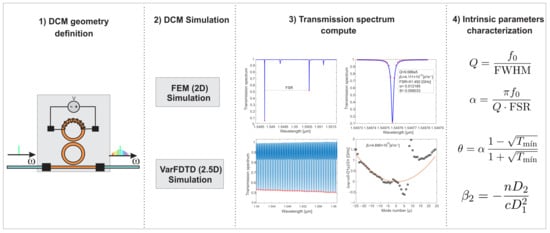
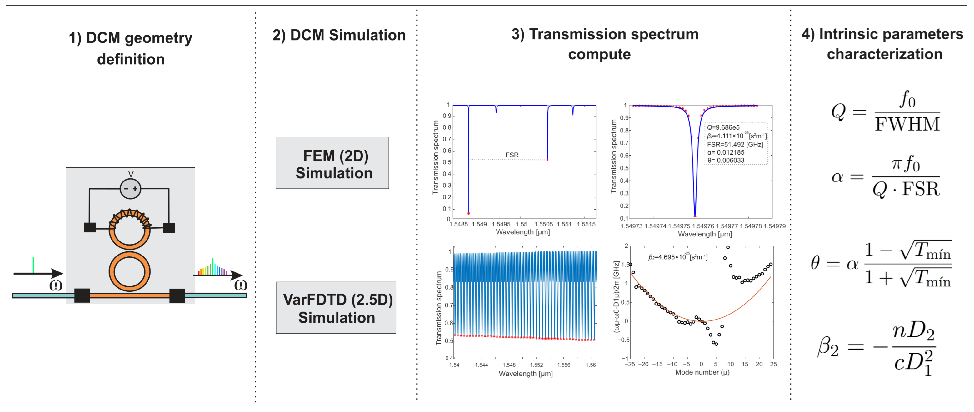
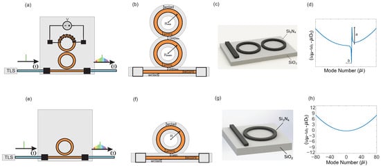
The DCM is characterized through a sequence of steps that relate the device geometry to its spectral response and physical parameters. The overall methodology is summarized in Figure 1.
Figure 1.
Geometry-driven characterization workflow of a DCM.
The procedure begins with the definition of the DCM geometry, followed by electromagnetic simulations to compute the transmission spectrum. From this spectral response, the intrinsic parameters of the system are extracted and analyzed as functions of the geometric configuration. This process establishes a systematic framework for connecting device geometry with the physical behavior of the DCM.
2.1. Step 1: Geometric Definition of the DCM
The first step of the geometry-based characterization consists of defining the physical structure of the DCM and the set of geometric parameters that determine its optical response. The DCM comprises a primary microring coupled to a straight bus waveguide and a secondary auxiliary ring placed in close proximity to the main cavity. This configuration enables controlled mode interactions between the two resonators, which are essential for engineering avoided mode crossings and tailoring the dispersion profile of the system.
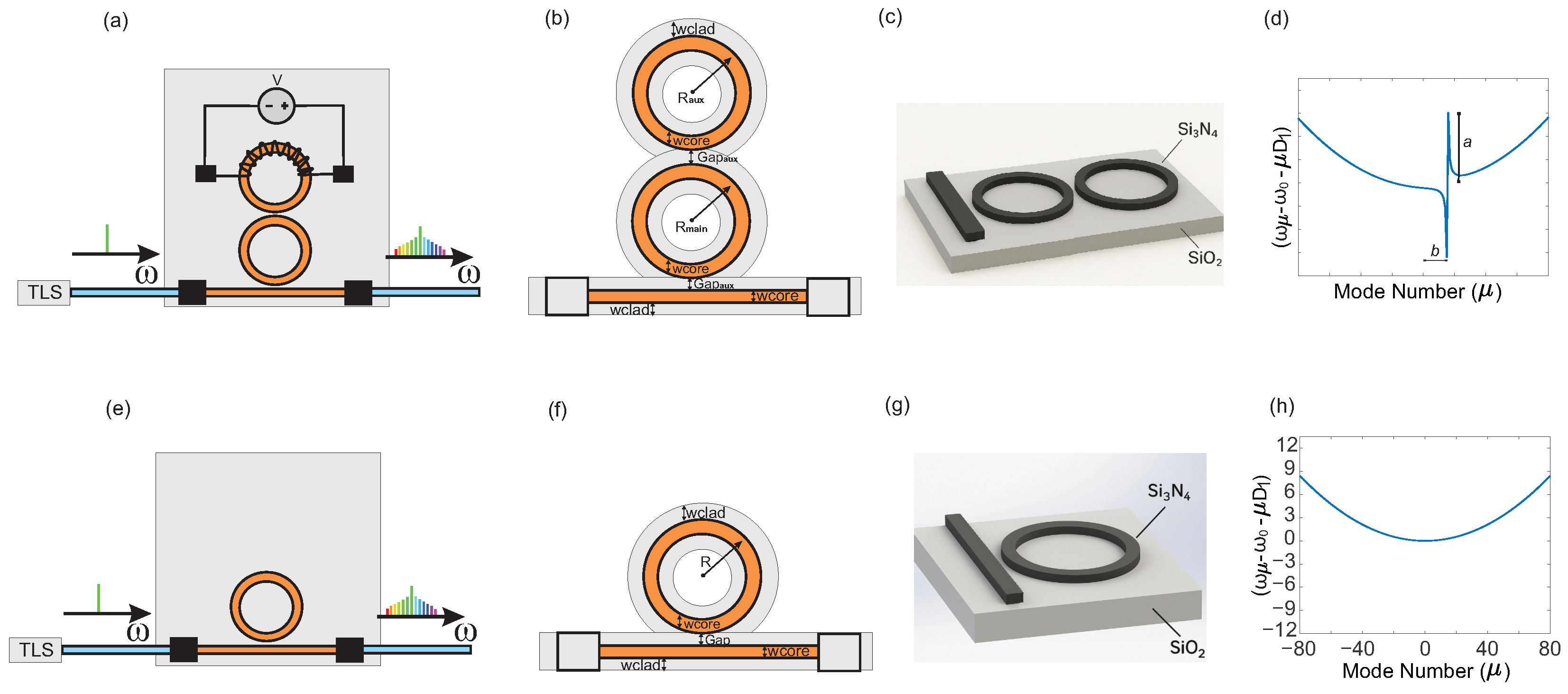
The device geometry is specified by the waveguide core width , the cladding dimensions, the radii of the main and auxiliary rings (, ), and the coupling gaps and . The main ring governs the fundamental resonant behavior of the cavity, whereas the auxiliary ring introduces an additional set of resonances that interacts with the primary mode family. The coupling gap between the bus waveguide and the main ring controls the external coupling, whereas the gap between the two rings determines the strength of the evanescent interaction responsible for mode hybridization. The geometric configuration used in this work is illustrated in Figure 2, and the corresponding parameters are summarized in Table 1.
Figure 2.
(a) DCM structure with a heater for auxiliary-ring tuning, modeled here as an effective refractive-index variation. (b) Geometry of the DCM structure. (c) DCM materials. (d) Dispersion profile of the DCM in the anomalous regime. (e) Structure of the single microring resonator (MRR). (f) Geometry of the MRR structure. (g) MRR materials. (h) Dispersion profile of the MRR in the anomalous regime.
Table 1.
Geometric parameters of optical microresonators.
The selected dimensions are consistent with typical integrated silicon platforms, ensuring low-loss propagation and suitable conditions for nonlinear optical processes. The material platform consists of a Si3N4 core embedded in a SiO2 cladding, as shown in Figure 2. The auxiliary ring is additionally defined as a tunable region to account for refractive-index variations induced by thermal control. In practice, this tuning is achieved by applying a voltage to an integrated heater, which modifies the temperature of the auxiliary cavity and, consequently, its refractive index through the thermo-optic effect. This mechanism enables controlled shifts in the spectral position of the auxiliary resonances and, therefore, in the location of the avoided mode crossings. Thermal tuning is represented through a controlled variation of the refractive index in the auxiliary ring, corresponding to the thermo-optic effect induced by a temperature change. This approach allows us to evaluate how the refractive-index variation modifies the avoided mode crossing and the DKS-generation conditions. However, it is important to clarify that this model does not solve the thermal distribution in the device and therefore should not be interpreted as a complete thermal or electro-thermal simulation. Consequently, effects such as non-uniform heating, heater geometry, heat dissipation, and thermal coupling between the rings are outside the scope of the present study and will be addressed in future work. For reference, a single microring resonator (MRR) is considered as a baseline configuration for comparison. However, the focus of this work remains on the DCM structure.
2.2. Step 2: Electromagnetic Modeling
Once the geometry of the DCM has been defined, the next step is to simulate the propagation of the optical field in order to obtain the transmission spectrum of the structure. This spectral response constitutes the basis for the subsequent extraction of the intrinsic parameters of the device. To perform this analysis, two complementary numerical methods are employed: the finite element method (FEM) and the variational finite-difference time-domain method (varFDTD).
The FEM model is implemented in two dimensions, as this formulation provides an accurate representation of the resonant response of the structure while keeping the computational cost within a feasible range. In particular, the 2D FEM approach is well suited to reproducing the shape of the resonances in the transmission spectrum, which is essential for the subsequent estimation of the quality factor Q, the loss coefficient , and the coupling coefficient . These quantities are extracted from the spectral characteristics of the resonator. The FEM formulation is based on the slowly varying envelope approximation (SVEA), which enables an efficient frequency-domain description of the electromagnetic field in resonant structures. Under this approximation, the field envelope satisfies
where is the complex electric-field envelope, is the phase function, and are the relative permeability and permittivity, is the conductivity, is the free-space wavenumber, is the angular frequency, and is the vacuum permittivity. In addition, the complex propagation constant is expressed as
where B describes the propagation term and accounts for losses in the medium.
A full three-dimensional FEM model would, in principle, allow the waveguide height to be explicitly included. This is particularly important for dispersion analysis, since the magnitude and sign of depend on the vertical confinement of the optical mode and, therefore, on the third dimension of the structure. However, 3D FEM simulations are computationally prohibitive for resonant devices of this scale, requiring substantial memory resources and long simulation times. As a result, 3D FEM is not a practical option for the iterative analysis required in this work. By contrast, the varFDTD method provides an efficient 2.5D approximation of the electromagnetic problem, significantly reducing the computational cost while retaining the effect of the waveguide height. This approach incorporates the vertical modal profile into an effective-index formulation, thereby accounting for the third dimension without requiring a full 3D simulation. Consequently, varFDTD is particularly well suited for the computation of chromatic dispersion. Starting from the scalar wave equation,
the field is approximated as
where is the vertical mode profile. This leads to an effective permittivity formulation that preserves the influence of the waveguide height on the propagation dynamics. For TE-like modes, the effective permittivity is expressed as
Therefore, both methods provide a continuous electromagnetic description of the field within the DCM. However, in order to obtain a numerical solution, these governing equations must be reformulated over a finite computational domain. This requires defining the spatial distribution of the material properties, discretizing the domain into finite elements, and specifying appropriate boundary and excitation conditions. In this way, the continuous field problem is transformed into a discrete system that can be solved numerically while preserving the physical behavior of the structure. Based on this formulation, the numerical implementation of the DCM is carried out by defining the material properties, discretizing the computational domain, and specifying the excitation and monitoring conditions required for field computation.
The structure consists of a Si3N4 core embedded in a SiO2 cladding, as shown in Figure 2b. The refractive indices of both materials are wavelength-dependent and are calculated using the Sellmeier equations. For Si3N4, the refractive index is given by
while for SiO2, it is expressed as
- FEM configuration
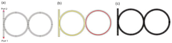
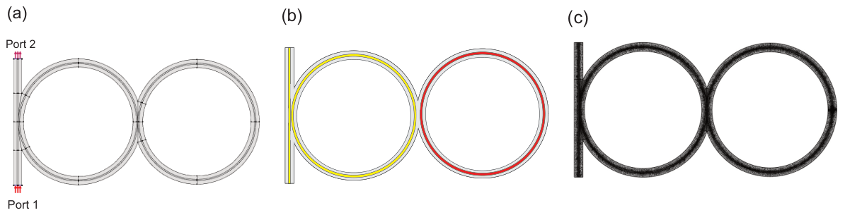
The FEM simulations are performed in a two-dimensional computational domain that includes the bus waveguide and the coupled resonators. Perfectly matched layers (PMLs) are applied at the domain boundaries to suppress artificial reflections. The domain is discretized using a region-dependent, non-uniform mesh, as shown in Figure 3c. The SiO2 cladding is assigned a coarser discretization, whereas the Si3N4 waveguide region is assigned a maximum allowed element size of . Additional local refinement is applied in the coupling regions between the rings to accurately resolve the evanescent interaction. The excitation is implemented using two ports. Port 1 defines the input excitation, where a continuous-wave signal with normalized power is injected. Since the FEM model is formulated in two dimensions, this excitation is expressed as optical power per unit out-of-plane length. Port 2 is used to monitor the output response, as shown in Figure 3a.
Figure 3.
(a) Optical excitation port in the DCM device. (b) Material assignment in the DCM device. Yellow: Si3N4; gray: SiO2; red: auxiliary-ring Si3N4 region where an effective refractive-index variation is applied to approximate thermo-optic tuning. (c) Mesh of the DCM device.
- varFDTD configuration
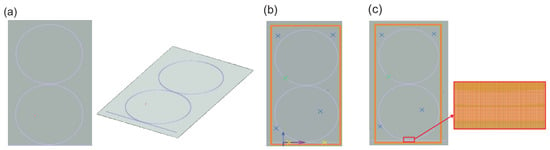
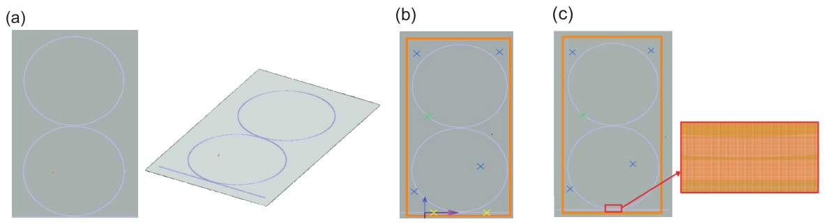
The varFDTD simulations are defined within a solver region that encloses the DCM structure and the SiO2 substrate, as shown in Figure 4a. The computational domain is discretized using an automatic non-uniform mesh generated according to the local wavelength, material refractive index, and geometrical interfaces. For the mesh setting used in this work, the discretization corresponds to approximately 26 mesh points per wavelength in the material. Around 1.55 μm and for the refractive index of Si3N4 used in the simulations, this gives an estimated local mesh step of about in the waveguide region. The mesh is therefore finer in the high-index Si3N4 waveguide and coupling regions, where field confinement and evanescent interaction are strongest, and coarser in the surrounding SiO2 cladding, as illustrated in Figure 4c. A continuous-wave source is launched at the input waveguide, performing a spectral sweep from to with 45,000 wavelength points. Field monitors are placed at the input and output sections to record the electromagnetic field, as shown in Figure 4b.
Figure 4.
(a) 2D and 3D views of the DCM device. (b) Optical source configuration for the DCM device. (c) Solver domain and mesh for the DCM device.
Once the electromagnetic problem has been solved using the FEM and varFDTD formulations, the optical field distribution within the structure is obtained. From this solution, the transmission spectrum is computed as the ratio between the optical power at the output and at the input of the device, providing a direct description of the interaction between the field and the resonant structure. The transmission spectrum is defined as
where and are obtained from the electromagnetic field evaluated at the input and output sections, respectively.
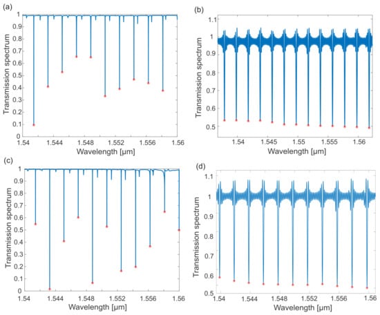
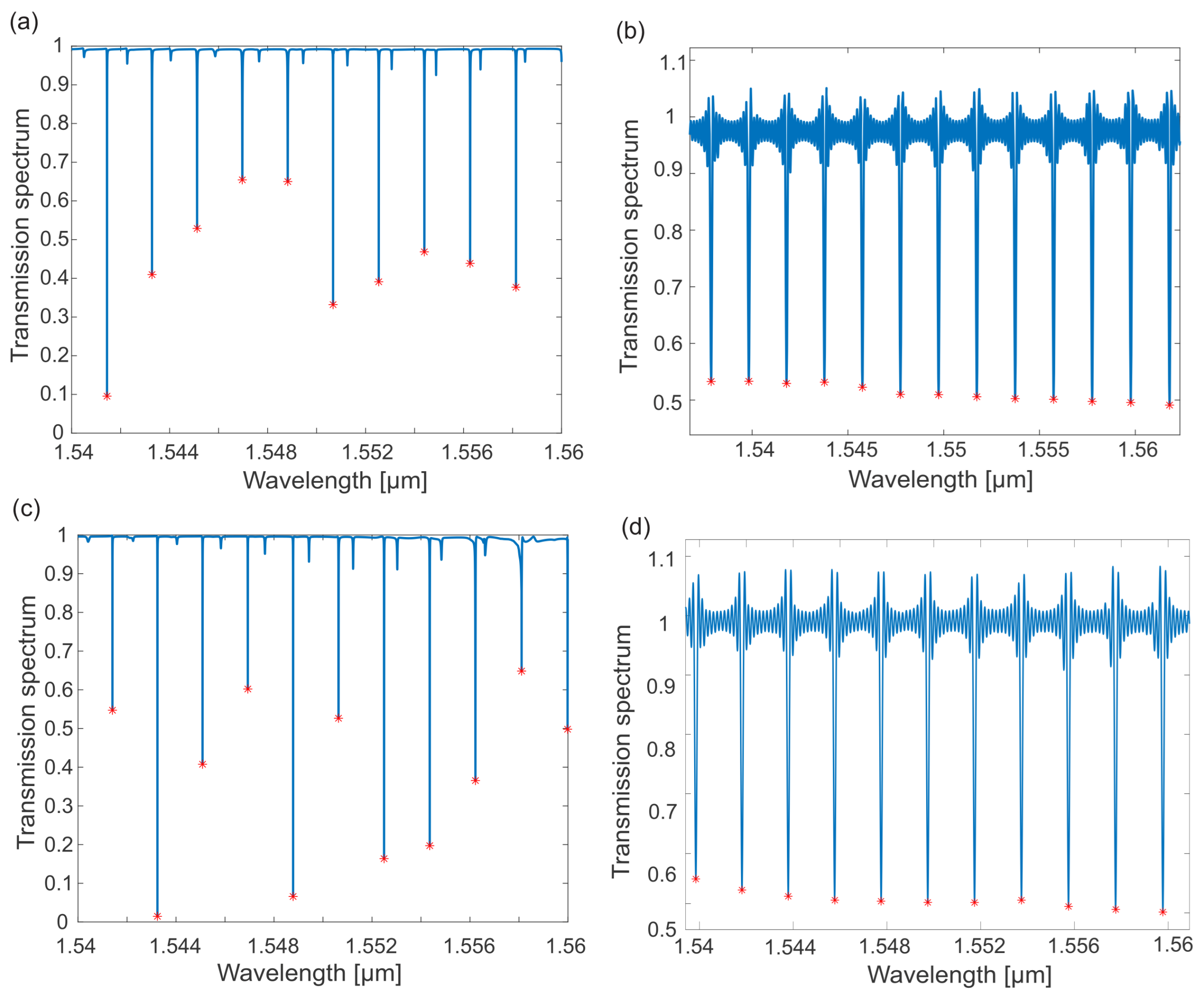
Figure 5a shows the transmission spectrum of the DCM. A series of resonances is observed, corresponding to wavelengths at which the optical field is efficiently coupled into the resonant cavities. In addition to the fundamental resonance pattern, localized distortions appear along the spectrum, indicating interaction between the main and auxiliary rings. These perturbations modify both the shape and the spectral position of the resonances, thereby revealing coupling between different modal families.
Figure 5.
(a) Transmission spectrum of the DCM computed using FEM. (b) Transmission spectrum of the DCM computed using VarFDTD. (c) Transmission spectrum of the MRR computed using FEM. (d) Transmission spectrum of the MRR computed using VarFDTD.
These features are consistent with the presence of AMXs, which arise from interactions between modes of both cavities. As a result, the spectral response deviates from a purely periodic behavior and exhibits localized variations in the resonance structure.
For comparison, Figure 5c shows the transmission spectrum of a MRR. In this case, the spectrum exhibits a regular sequence of resonances with quasi-periodic spacing. The separation between resonances is primarily determined by the cavity round-trip condition, although slight variations in the free spectral range (FSR) arise from the wavelength dependence of the effective refractive index, that is, from chromatic dispersion. The comparison between both configurations highlights the impact of the auxiliary resonator on the spectral response. Whereas the MRR exhibits a regular resonance pattern, the DCM introduces controlled spectral perturbations associated with mode interactions, which play a key role in dispersion engineering and DKS generation.
2.3. Step 3: Extraction of Intrinsic Parameters
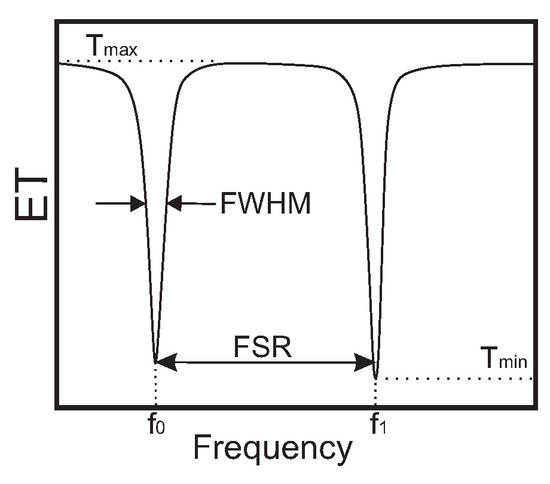
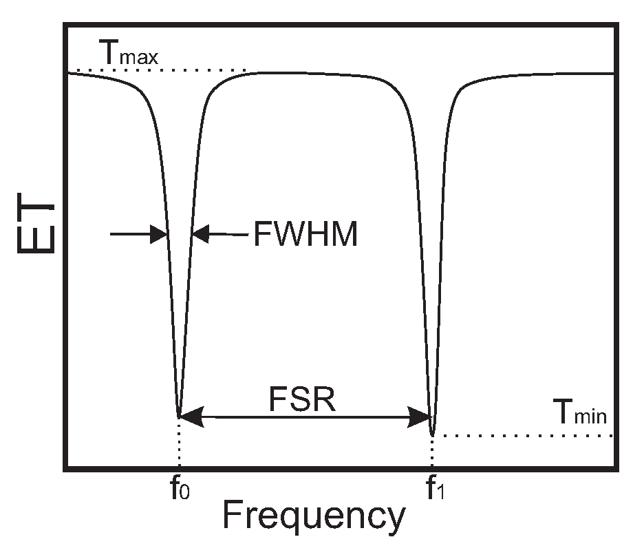
The intrinsic parameters of the DCM are extracted from the transmission spectrum by analyzing the spectral characteristics of individual resonances. Figure 6 illustrates the key quantities involved in this process, including the resonance frequency , the full width at half maximum (FWHM), the minimum transmission , and the free spectral range (FSR).
Figure 6.
Intrinsic parameters identified from the transmission spectrum: resonance frequency , full width at half maximum (FWHM), minimum transmission , and free spectral range (FSR).
Each resonance is modeled using a Lorentzian function, which provides an accurate description of the cavity response in the vicinity of resonance. The Lorentzian profile is expressed as
where A is the amplitude, is the resonance frequency, and FWHM represents the linewidth. This fitting procedure enables accurate estimation of the spectral parameters required for device characterization.
The extraction procedure is applied to the transmission spectrum of the DCM. From the Lorentzian fitting of individual resonances, the parameters , FWHM, , and FSR are obtained. Although this procedure can be applied to any resonance, the analysis is restricted to high-Q resonances, as these are associated with lower losses and enhanced energy confinement within the cavity. Such conditions are more favorable for nonlinear interactions and increase the likelihood of DKS generation. Using these quantities, the intrinsic parameters of the resonator are then computed as follows:
where and is the second-order dispersion coefficient. In the DCM, the resonance frequencies are indexed by the mode number and are described by a dispersion relation that includes the perturbation induced by mode interaction,
where is the angular frequency of the reference resonance, a quantifies the interaction strength, and b determines its spectral position. The last term captures the distortion induced by the AMX, thereby enabling the dispersion profile of the DCM to be fitted beyond the ideal quadratic behavior.
For comparison, the same extraction procedure is applied to the MRR. In this case, the spectral parameters , FWHM, , and FSR are obtained from the selected resonances using the Lorentzian fitting procedure described above. This comparison provides a reference for evaluating the intrinsic parameters in a single-cavity configuration, in contrast to the DCM, where the auxiliary ring introduces additional mode interactions that modify the spectral response.
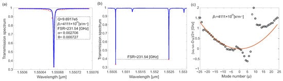
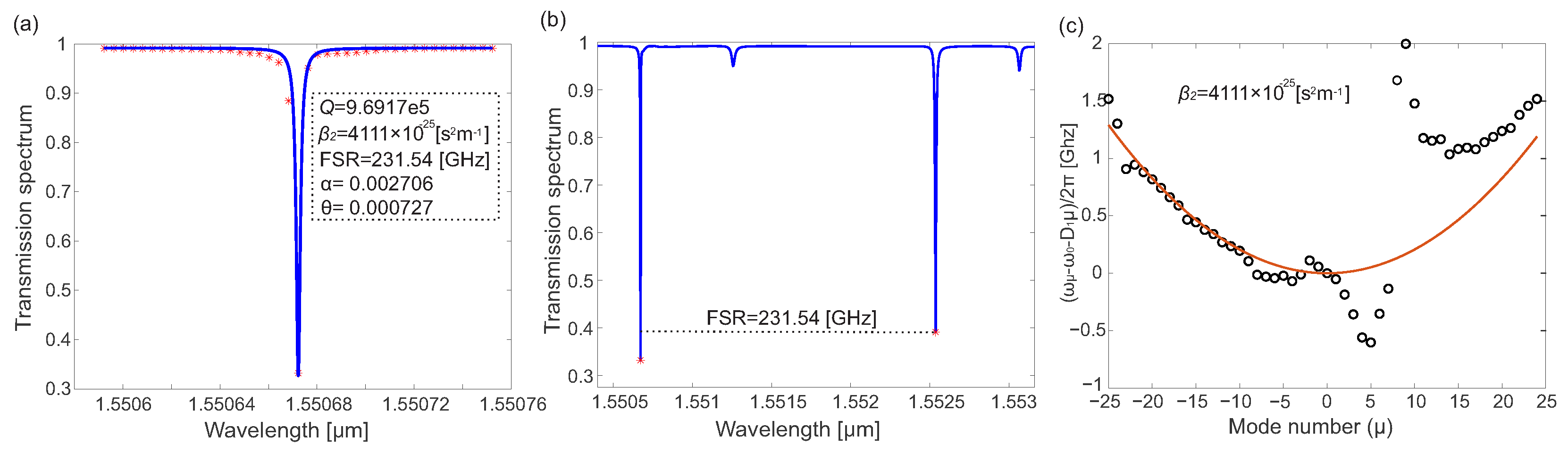
Figure 7a shows the Lorentzian fit of the selected DCM resonance, centered at approximately . This resonance is selected because of its high quality factor, as high-Q resonances are associated with reduced losses and enhanced intracavity energy buildup, both of which are desirable for DKS generation. From the fit, the parameters , FWHM, and are obtained and subsequently used to determine Q, , and . The extracted values are consistent with those reported for Si3N4 integrated resonators, indicating that the selected geometry provides low-loss operation and suitable coupling conditions.
Figure 7.
(a) Intrinsic parameters for the DCM with main-ring radius of . (b) FSR value. (c) Dispersion profile for the DCM with main-ring radius of .
Figure 7b shows the corresponding FSR, with a value of , consistent with the designed cavity dimensions. Figure 7c presents the associated dispersion profile obtained from the resonance frequencies. The DCM operates in the anomalous-dispersion regime, which is a necessary condition for DKS generation. In addition, deviations from the expected quadratic trend reveal the presence of an avoided mode crossing. In this case, the AMX is located at approximately , confirming that the auxiliary cavity induces a localized perturbation in the modal evolution of the system. This result demonstrates that the selected DCM geometry enables the mode interaction required for local dispersion engineering.
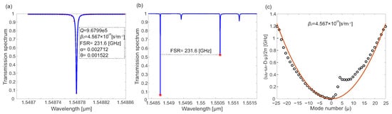
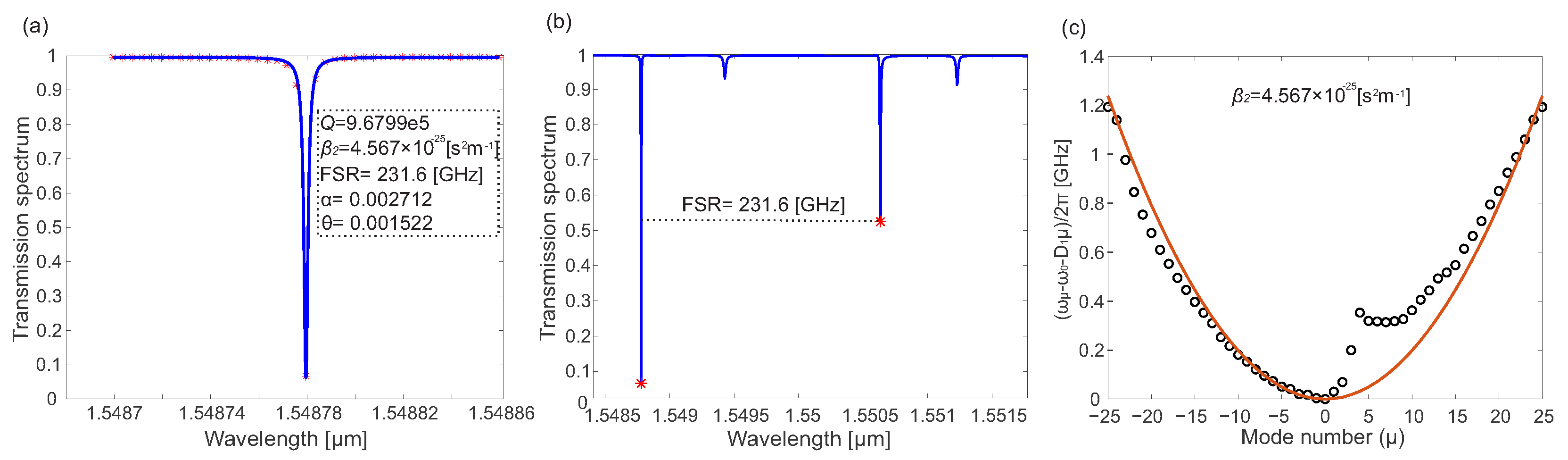
For comparison, the same characterization is carried out for the MRR with radius . The selected resonance is located at and, as in the DCM case, is chosen because of its high quality factor. Figure 8a shows the Lorentzian fit and the extracted intrinsic parameters for the MRR. The obtained values fall within the ranges commonly reported for Si3N4 microresonators, supporting the validity of the fitting procedure and the extraction model. The high quality factor confirms low losses and strong intracavity field buildup, both of which are favorable for nonlinear operation. These results validate the selected MRR geometry as a suitable reference for comparison with the DCM. The corresponding MRR dispersion profile is shown in Figure 8c. The resonator also operates in the anomalous-dispersion regime, confirming that the selected dimensions satisfy the dispersion requirement for DKS generation. Although the overall behavior follows the expected quadratic trend, small deviations are observed due to higher-order modal contributions. In contrast to the DCM, no additional perturbation associated with an auxiliary cavity is present.
Figure 8.
(a) Intrinsic parameters for the MRR with radius . (b) FSR value. (c) Dispersion profile.
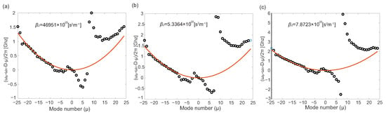
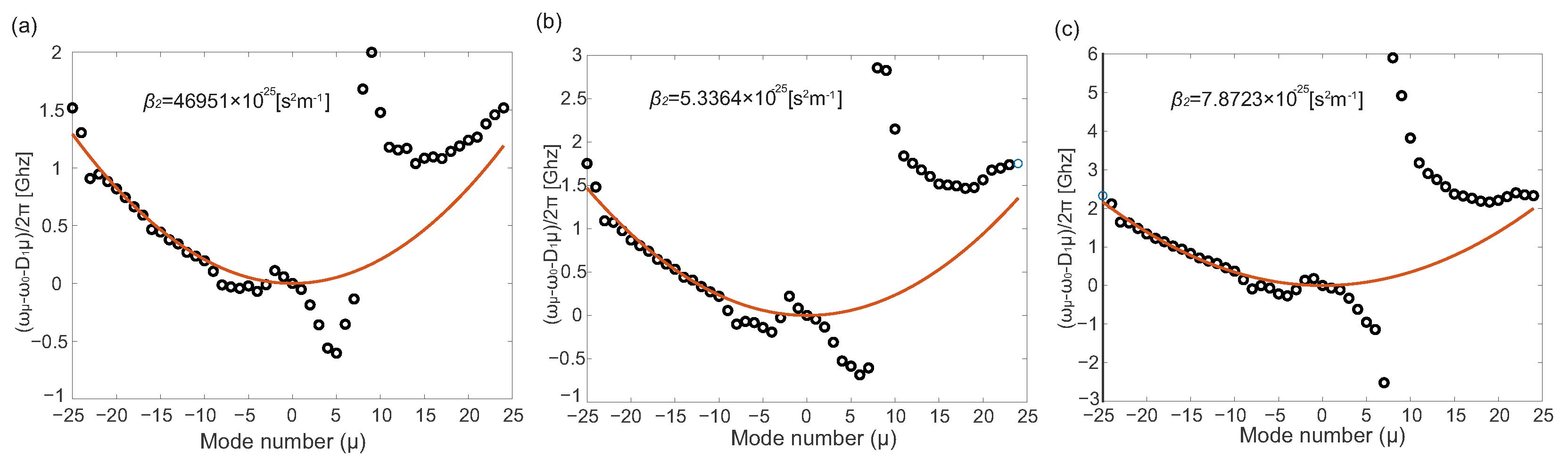
Once the baseline response of the DCM has been established, the influence of the gap between the main and auxiliary cavities is analyzed. Figure 9 shows the dispersion profiles for , , and . As the gap decreases, the interaction between the cavities becomes stronger, leading to an increase in the interaction parameter a from approximately to nearly . At the same time, the curvature of the dispersion profile becomes more pronounced, and increases from to . These results indicate that the auxiliary-ring gap controls the strength of the AMX. This observation is particularly relevant from a design perspective, as it shows that the gap can be used as a direct geometric parameter to control the AMX strength.
Figure 9.
(a) Dispersion profile for the DCM with . (b) Dispersion profile for the DCM with . (c) Dispersion profile for the DCM with .
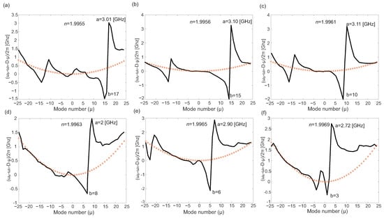
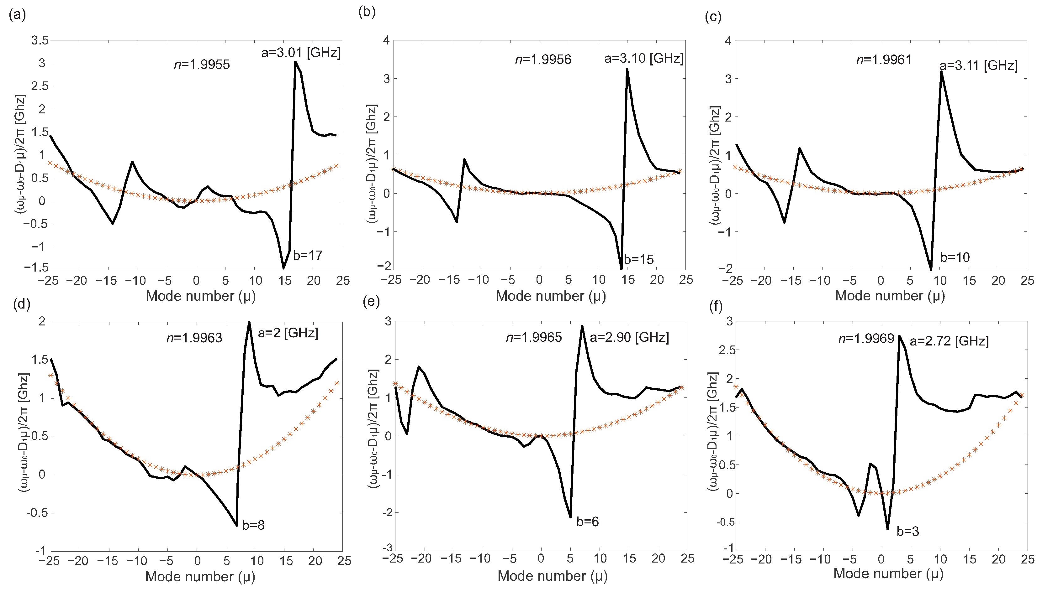
The refractive index of the auxiliary ring is then varied to emulate thermal tuning. In this analysis, the index is swept from to , corresponding to the expected thermo-optic variation of Si3N4. The objective is to determine how the spectral position of the AMX evolves under these changes. For , the resulting dispersion profiles are shown in Figure 10. A clear displacement of the interaction point is observed as the refractive index increases. In particular, the parameter b, which represents the spectral position of the AMX, decreases progressively. This behavior originates from the spectral shift of the auxiliary-cavity resonances, which modifies the interaction point with the main-cavity mode family.
Figure 10.
(a) Dispersion profile for and . (b) Dispersion profile for and . (c) Dispersion profile for and . (d) Dispersion profile for and . (e) Dispersion profile for and . (f) Dispersion profile for and .
This result is particularly relevant because it shows that thermal tuning provides direct control over the spectral position of the AMX. In our previous work on deterministic DKS generation in DCMs, several strategic configurations were identified as favorable for stable and accessible DKS generation, where a represents the AMX interaction strength and b defines its modal position. These parameters modify the local dispersion landscape and therefore influence the accessibility of stable DKS states in the nonlinear cavity dynamics, namely , , , and . Among these, configurations with were identified as the most feasible for physical implementation. The displacement of b observed here therefore provides a mechanism for steering the interaction toward modal positions previously identified as favorable for deterministic DKS generation.
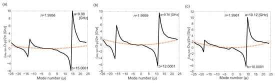
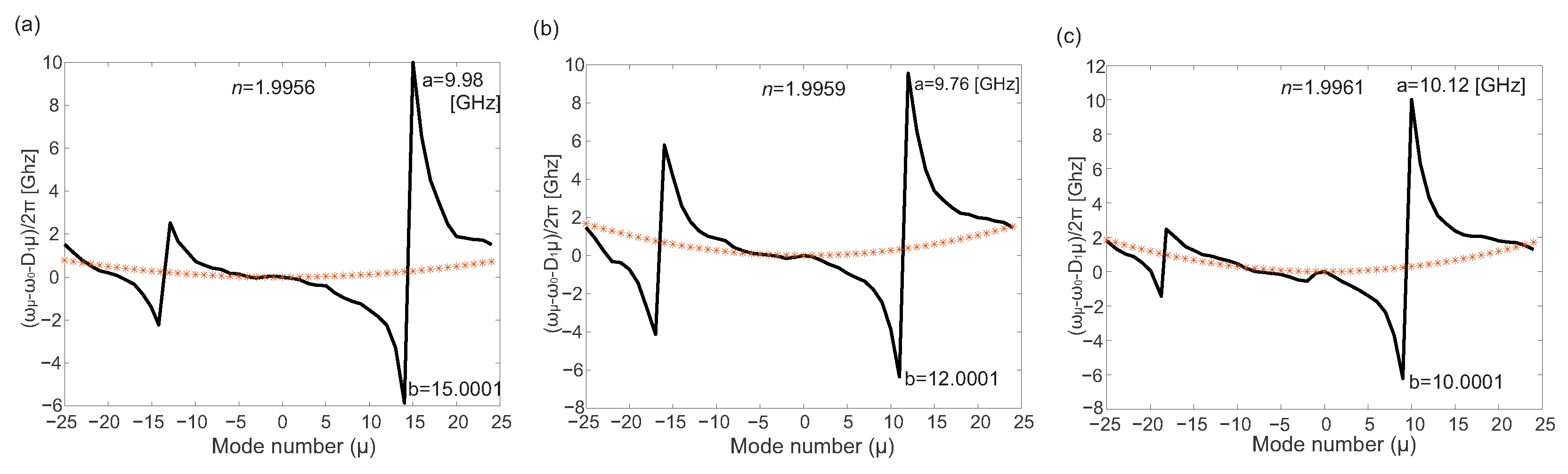
Finally, the gap is reduced to to further enhance the interaction strength. The resulting profiles are shown in Figure 11. Under this condition, the interaction strength approaches , while the position of the AMX remains within strategically relevant regions. In particular, for the fitted parameters are and ; for , and ; and for , and . These results demonstrate that the proposed geometric design enables access to several of the configurations previously identified as favorable for deterministic DKS generation [14].
Figure 11.
(a) Dispersion profile for and . (b) Dispersion profile for and . (c) Dispersion profile for and .
Overall, these results demonstrate that the DCM geometry provides two independent control parameters over the AMX. The determines the interaction strength a, whereas the refractive index of the auxiliary ring controls its spectral position b. More importantly, the present geometric characterization shows that these parameters can be tuned toward values previously identified as favorable for deterministic DKS generation. In this way, the proposed methodology establishes a direct connection between geometric design and the mode-interaction conditions required for stable and accessible soliton operation.
3. Deterministic DKS Generation
The extracted intrinsic parameters are used to evaluate the ability of the designed DCM to support deterministic DKS generation, following the methodology introduced in [14]. The procedure comprises three stages. First, the parameter space is characterized to identify the operating regions of the resonator and locate the DKS region. Next, generation paths are defined to reach this region while avoiding the chaotic zone by means of a constant pump power and a linear detuning sweep. Finally, the selected paths are tested under different realizations of the initial noise, and a stability analysis is performed to verify reproducible convergence toward a stable DKS state.
Parametric Analysis of for DKS Generation
The extracted intrinsic parameters are subsequently incorporated into a nonlinear model to evaluate the conditions for DKS generation. The dynamical response of the DCM is analyzed in the parametric space defined by the normalized detuning and the normalized pump power , following the methodology introduced in [14]. In contrast to previous studies, this analysis is performed for a physically defined DCM whose intrinsic properties are directly obtained from its geometry. The intracavity dynamics are described by the Lugiato–Lefever equation (LLE), including an additional term that accounts for the AMX induced by the auxiliary ring. This interaction is essential in the DCM because it locally modifies the dispersion profile and therefore changes the accessibility of the DKS region in the space. The governing equation is written as
where is the complex envelope of the intracavity field, t is the slow-time variable, is the fast-time variable, is the round-trip time, is the total loss per round trip, is the pump–cavity detuning, L is the cavity length, is the second-order dispersion coefficient, is the Kerr nonlinear coefficient, is the coupling coefficient between the bus waveguide and the resonator, is the pump field, and a and b denote the strength and spectral position of the mode interaction, respectively. The Fourier component is defined as
The AMX term is included to account for modal interactions between the main and auxiliary rings in the DCM, which locally perturb the resonance evolution and modify the dispersion profile. The parameters a and b are directly obtained from the geometry-based characterization described in the previous section and incorporated into the deterministic-generation framework reported in [14]. This approach enables the evaluation of DKS-generation conditions in physically realizable DCM geometries.
To analyze the operating regions of the DCM, the detuning and pump field are expressed in normalized form as
so that the nonlinear dynamics can be analyzed directly in the parameter space. This normalization is adopted because it provides the standard framework used to identify the different operating regions of the resonator and to define the DKS-generation paths.
The intrinsic parameters used in the simulations correspond to the DCM designed and characterized in the previous section, with a main-ring radius of . In particular, the values , , , , , and are directly obtained from this characterization. This establishes a direct link between device geometry and nonlinear dynamics, thereby enabling the evaluation of deterministic DKS generation. The numerical solution of Equation (15) is obtained using the split-step Fourier method. This approach is adopted because the LLE contains both linear dispersive terms and nonlinear Kerr terms, and the split-step formulation provides an efficient and stable strategy to propagate the intracavity field by separating both contributions over small temporal increments. In each iteration, the linear part is evaluated in the Fourier domain, whereas the nonlinear phase evolution is computed in the time domain. This makes the method particularly suitable for modeling Kerr-comb dynamics in microresonators, where the simultaneous action of dispersion, loss, detuning, and nonlinearity must be resolved over many round trips. To emulate realistic operating conditions, the intracavity field is initialized with Gaussian noise. In particular, a noise term with standard deviation is added at each iteration. This initialization is important because soliton formation in resonators is highly sensitive to perturbations of the intracavity field, and the use of noise allows the simulations to reproduce the stochastic conditions under which the optical field evolves in practice.
The initial pump conditions are selected such that the system starts in a well-defined comb-generation regime before the detuning variation. For the DCM, the pump is initialized at with , corresponding to . These values provide a consistent starting point for accessing DKS-supporting regions in the parametric space while remaining compatible with the deterministic-generation framework reported in [14]. With the model, parameters, and numerical scheme thus defined, the next step is to compute the number of temporal peaks obtained after the intracavity field evolves under each pair . This procedure makes it possible to map the dynamical regions of the DCM and identify the area in which DKS states can be accessed through a simple detuning sweep under constant pump power.
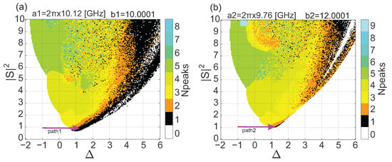
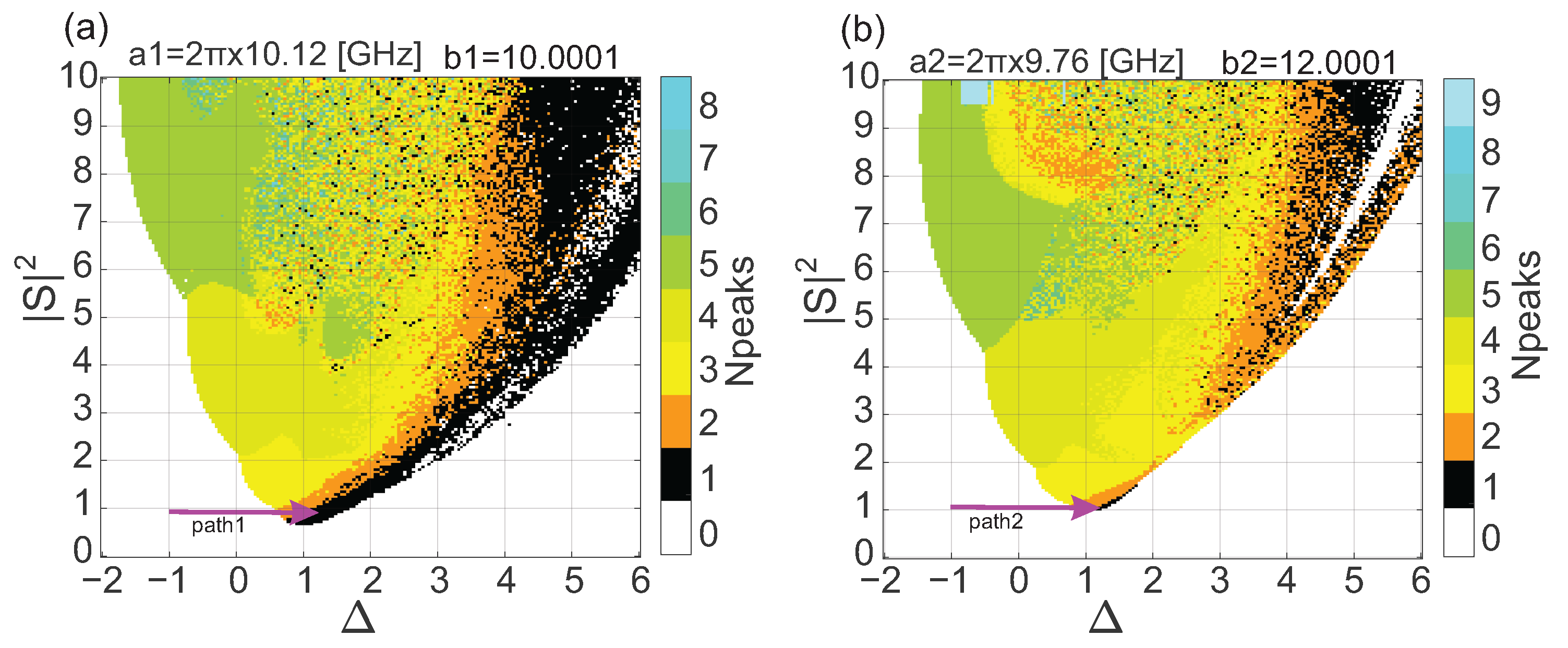
Figure 12 shows the parametric maps obtained for the two DCM configurations considered in this work, namely and . In both cases, the space exhibits a well-defined DKS region located in the lower-right part of the map, indicating that the geometrically engineered mode interaction shifts the soliton regime toward an experimentally accessible operating region. Both configurations are compatible with the simple generation route based on constant pump power and a linear blue-to-red detuning sweep previously reported in [14].
Figure 12.
Parametric maps in the space for the selected DCM configurations: (a) , and (b) . The black region corresponds to DKS states.
The relevance of these results lies in the fact that the accessible DKS region is directly determined by interaction conditions controlled by the device geometry. In particular, refractive-index tuning in the auxiliary ring shifts the parameter b and therefore the position of the AMX along the modal axis, enabling the DKS region to be placed within a favorable area of the space. This demonstrates that thermal control of the auxiliary ring acts as an effective design parameter for achieving experimentally viable DKS access. Furthermore, the obtained configurations provide access to mode-interaction conditions consistent with deterministic DKS generation within the framework introduced in [14], thereby establishing a direct link between geometric design, AMX positioning, and accessible operating regimes.
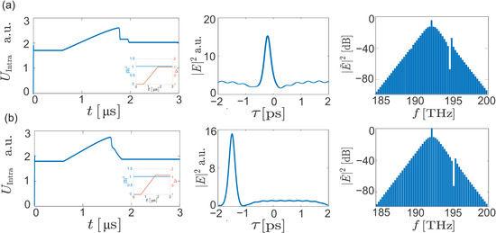
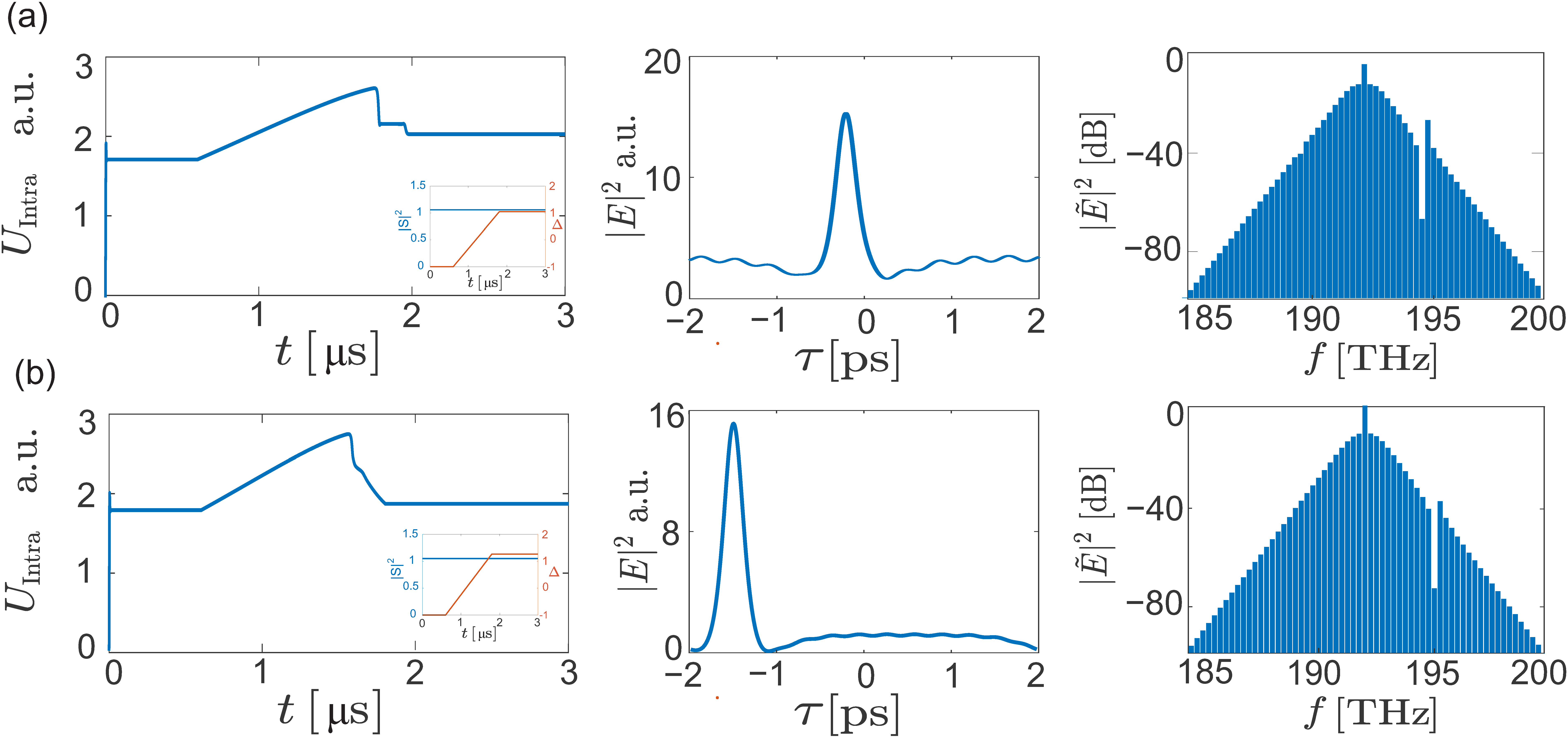
Figure 13 shows the total intracavity energy , the temporal intensity profile, and the optical spectrum obtained along the two selected generation paths corresponding to the interaction configurations and . For , the path is defined by a constant normalized pump power and a linear detuning sweep from to , whereas for it is defined by and a detuning sweep from to . In both cases, evolves smoothly and converges to a nearly constant final value, indicating stable evolution of the intracavity field along the selected path. The temporal intensity profile exhibits a single peak within one cavity round trip, while the optical spectrum displays the broadband envelope characteristic of a DKS state. These results indicate that both generation paths drive the system toward the same soliton regime, confirming that the regions identified in the space correspond to accessible operating conditions for DKS generation.
Figure 13.
DKS generation results for the selected interaction configurations: (a) and (b) . For each configuration, the panels show the intracavity energy evolution (left), the temporal intensity profile (center), and the optical spectrum (right).
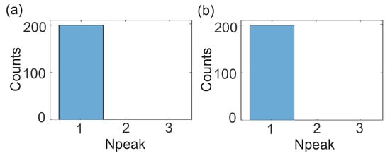
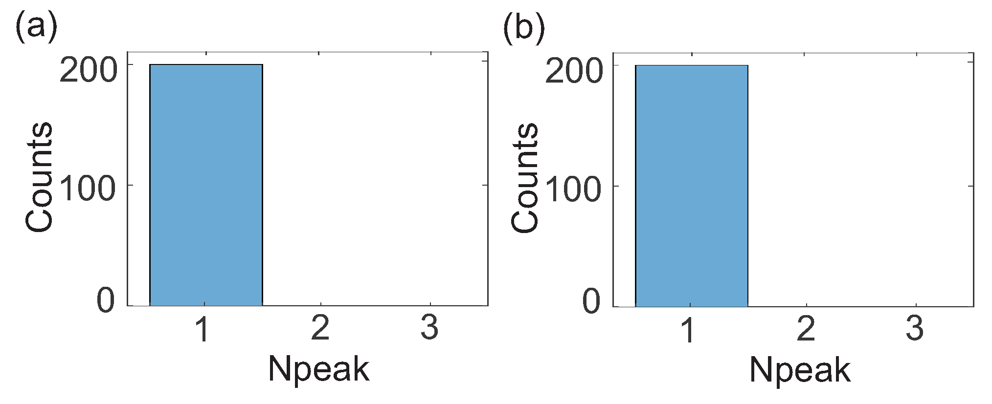
To evaluate whether the selected generation paths are truly deterministic, the LLE simulation is repeated 200 times for each interaction configuration while preserving the same path in the space and varying only the realization of the initial Gaussian noise, with standard deviation . In all cases, the system converges to a final state with , corresponding to a single temporal pulse (See Figure 14). These results confirm that, for both and , the selected paths reproducibly lead to the same DKS solution and therefore exhibit deterministic behavior.
Figure 14.
Deterministic-generation validation for the two selected interaction configurations, (a) and (b) .
To assess the sensitivity of DKS generation to fabrication tolerances, a Monte Carlo analysis was performed by perturbing the intrinsic parameters extracted from the designed DCM. In the proposed framework, the geometry defines the nominal values of R, , , and . However, fabrication errors may lead to deviations from the target geometry, thereby modifying the effective values of these parameters. Therefore, the variation ranges reported in Table 2 were selected to represent possible fabrication-induced changes in the intrinsic parameters. The perturbed parameters were then propagated through the LLE model to evaluate whether the proposed generation paths remain capable of reaching the single-DKS regime under fabrication-related deviations.
Table 2.
Parameter ranges used to represent fabrication-induced tolerances in the Monte Carlo analysis.
In this analysis, the parameters radius, , , and were randomly varied within the ranges listed in Table 2. For each realization, the same generation paths previously defined for and were applied, and the final state of the intracavity field was classified according to the number of temporal peaks. This procedure makes it possible to determine whether the proposed DCM geometries retain their ability to generate a single DKS under realistic fabrication tolerances.
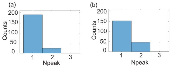
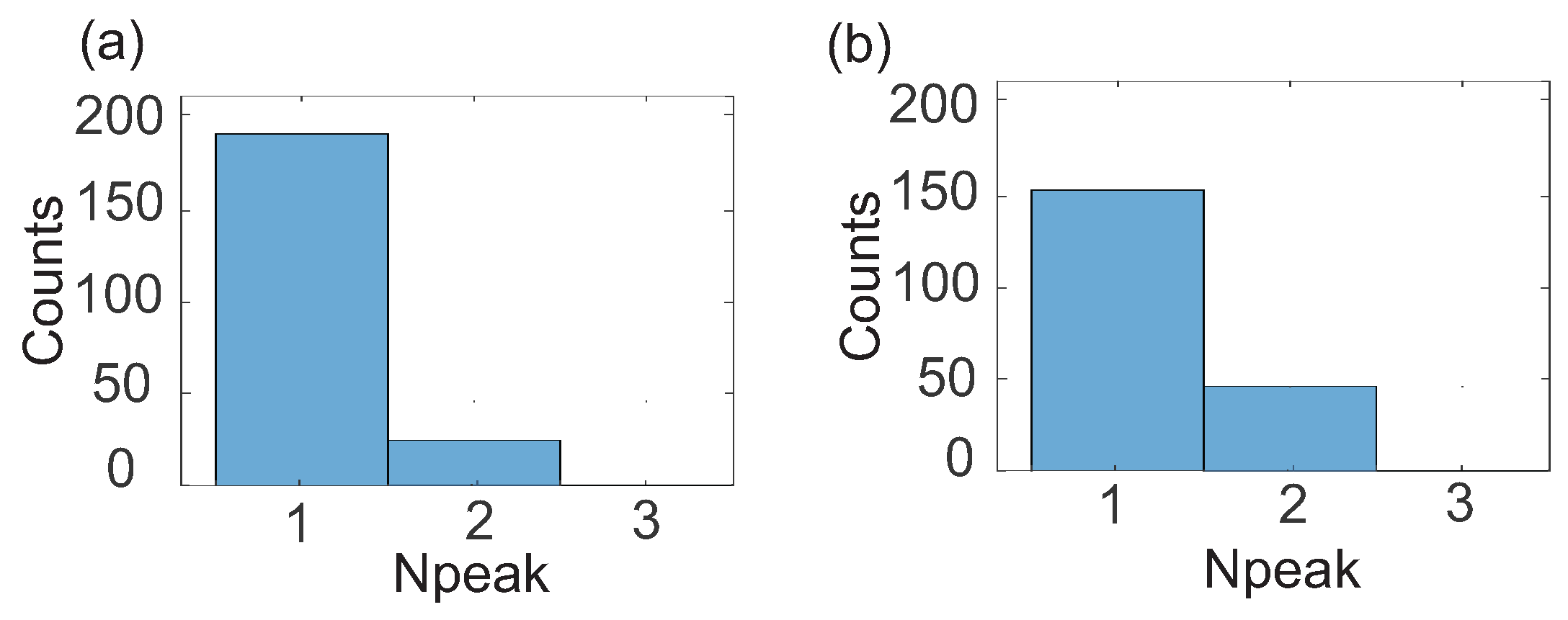
Figure 15 summarizes the Monte Carlo results obtained for the two selected interaction configurations. For , DKS generation was obtained in 180 out of 200 realizations, whereas for , it was obtained in 150 cases. These results correspond to generation probabilities of 90% and 75%, respectively, indicating that the proposed generation paths maintain a high probability of accessing the DKS regime even when the intrinsic parameters deviate from their nominal values because of fabrication tolerances. These results support the proposed simulation workflow as a pre-fabrication design tool, enabling the identification of robust geometries and operating paths before physical implementation.
Figure 15.
Monte Carlo histograms of the number of temporal peaks obtained for 200 simulations with randomly varied intrinsic DCM parameters: (a) configuration , and (b) configuration .
Although the perturbations introduced in the intrinsic parameters modify the final outcome in some realizations. This result is relevant because it shows that the proposed DCM geometries are not restricted to an ideal nominal design, but instead preserve their potential for DKS generation under realistic dimensional variations. In this sense, the geometry-based methodology developed in this work provides not only feasible nominal dimensions, but also operating conditions with a degree of tolerance compatible with practical fabrication.
4. Conclusions
This work demonstrates that deterministic DKS generation in Si3N4 DCM can be achieved using physically realizable device geometries. A direct link is established between the geometric design of the DCM and the intrinsic and interaction parameters required for DKS operation. The results show that the auxiliary-ring gap controls the interaction strength, whereas refractive-index tuning of the auxiliary ring shifts the spectral position of the AMXs. Through this combined control, the designed structures reproduce interaction conditions that place the DKS region in an accessible part of the parameter space. These operating regions support simple generation paths based on constant pump power and linear detuning sweeps, thereby reducing the control complexity required to access the soliton regime. The temporal and spectral responses confirm soliton formation, while repeated simulations under different initial-noise realizations verify the deterministic nature of the generated states. The proposed simulation-based methodology serves as a pre-fabrication design tool for identifying robust geometries and operating conditions prior to physical implementation of DCM devices. Future work will extend this framework by incorporating a coupled electro-thermal and electromagnetic model to compute the refractive-index perturbation from the temperature distribution generated by localized heaters, including non-uniform heating and thermal crosstalk between the coupled resonators. Overall, these results provide a practical route from DCM geometry to deterministic DKS generation under simplified control conditions, and establish a direct foundation for the experimental development of DCM-based soliton sources.
Author Contributions
Methodology and implementation, A.F.C.-S.; conceptualization and investigation, M.B.M. and N.G.G.; supervision, writing, and review, J.A.J.-V. All authors have read and agreed to the published version of the manuscript.
Funding
This research was supported by the Universidad Tecnológica de Pereira and the Universidad Nacional de Colombia, with financial support by the European Regional Development Fund within the Operational Program “Bulgarian national recovery and resilience plan” and the procedure for direct provision of grants “Establishing of a network of research higher education institutions in Bulgaria”, under the Project BG-RRP-2.004-0005 “Improving the research capacity and quality to achieve international recognition and resilience of TU-Sofia”.
Institutional Review Board Statement
Not applicable.
Informed Consent Statement
Not applicable.
Data Availability Statement
The data presented in this study are available on request from the corresponding author.
Conflicts of Interest
The authors declare that they have no known competing financial interests or personal relationships that could have appeared to influence the work reported in this paper.
References
- Kippenberg, T.J.; Gaeta, A.L.; Lipson, M.; Gorodetsky, M.L. Dissipative Kerr solitons in optical microresonators. Science 2018, 361, eaan8083. [Google Scholar] [CrossRef] [Scilit] [PubMed]
- Gaeta, A.L.; Lipson, M.; Kippenberg, T.J. Photonic-chip-based frequency combs. Nat. Photonics 2019, 13, 158–169. [Google Scholar] [CrossRef] [Scilit]
- Herr, T.; Brasch, V.; Jost, J.D.; Wang, C.Y.; Kondratiev, N.M.; Gorodetsky, M.L.; Kippenberg, T.J. Temporal solitons in optical microresonators. Nat. Photonics 2014, 8, 145–152. [Google Scholar] [CrossRef] [Scilit]
- Okawachi, Y.; Saha, K.; Levy, J.S.; Wen, Y.H.; Lipson, M.; Gaeta, A.L. Octave-spanning frequency comb generation in a silicon nitride chip. Opt. Lett. 2011, 36, 3398–3400. [Google Scholar] [CrossRef] [Scilit] [PubMed]
- Coen, S.; Randle, H.G.; Sylvestre, T.; Erkintalo, M. Modeling of octave-spanning Kerr frequency combs using a generalized mean-field Lugiato–Lefever model. Opt. Lett. 2013, 38, 37–39. [Google Scholar] [CrossRef] [Scilit] [PubMed]
- Parra-Rivas, P.; Gomila, D.; Matías, M.A.; Coen, S.; Gelens, L. Dynamics of localized and patterned structures in the Lugiato–Lefever equation. Phys. Rev. A 2014, 89, 043813. [Google Scholar] [CrossRef] [Scilit]
- Jaramillo-Villegas, J.A.; Xue, X.; Wang, P.H.; Leaird, D.E.; Weiner, A.M. Deterministic single soliton generation and compression in microring resonators avoiding the chaotic region. Opt. Express 2015, 23, 9618–9626. [Google Scholar] [CrossRef] [Scilit] [PubMed]
- Joshi, C.; Jang, J.K.; Luke, K.; Ji, X.; Miller, S.A.; Klenner, A.; Okawachi, Y.; Lipson, M.; Gaeta, A.L. Thermally controlled comb generation and soliton modelocking in microresonators. Opt. Lett. 2016, 41, 2565–2568. [Google Scholar] [CrossRef] [Scilit] [PubMed]
- Brasch, V.; Geiselmann, M.; Herr, T.; Lihachev, G.; Pfeiffer, M.H.P.; Gorodetsky, M.L.; Kippenberg, T.J. Photonic chip–based optical frequency comb using soliton Cherenkov radiation. Science 2016, 351, 357–360. [Google Scholar] [CrossRef] [Scilit] [PubMed]
- Bao, C.; Xuan, Y.; Leaird, D.E.; Wabnitz, S.; Qi, M.; Weiner, A.M. Spatial mode-interaction induced single soliton generation in microresonators. Optica 2017, 4, 1011–1015. [Google Scholar] [CrossRef] [Scilit]
- Zhai, Y.; Liu, J.; Jia, L.; Zhang, F. Dissipative Kerr soliton formation in dual-mode interaction Si3N4 microresonators. APL Photonics 2024, 9, 101304. [Google Scholar] [CrossRef] [Scilit]
- Xue, X.; Xuan, Y.; Liu, Y.; Wang, P.-H.; Chen, S.; Wang, J.; Leaird, D.E.; Qi, M.; Weiner, A.M. Mode interaction aided excitation of dark solitons in microresonators constructed of normal dispersion waveguides. arXiv 2015, arXiv:1404.2865. [Google Scholar] [CrossRef] [Scilit]
- Wang, C.Y.; Yang, Q.F.; Ji, X.; Brasch, V.; Geiselmann, M.; Yu, M.; Kippenberg, T.J. Mid-infrared optical frequency combs at 2.5 μm based on crystalline microresonators. Nat. Commun. 2016, 4, 1345. [Google Scholar] [CrossRef] [Scilit]
- Calvo-Salcedo, A.F.; González, N.G.; Jaramillo-Villegas, J.A. Obtaining dissipative Kerr solitons deterministically using dual-coupled microresonators. Appl. Sci. 2024, 14, 10819. [Google Scholar] [CrossRef] [Scilit]
- Calvo-Salcedo, A.F.; Marinov, M.B.; González, N.G.; Jaramillo-Villegas, J.A. Automatic Detection of TiO2 Nanoparticles Using Dual-Coupled Microresonators and Deep Learning. Technologies 2026, 14, 65. [Google Scholar] [CrossRef] [Scilit]
- Stone, B.D.; Rukh, L.; Colación, G.M.; Drake, T.E. Reduction of thermal instability of soliton states in coupled Kerr microresonators. APL Photonics 2025, 10, 051301. [Google Scholar] [CrossRef] [Scilit]
- Sanyal, S.; Okawachi, Y.; Zhao, Y.; Kim, B.Y.; McNulty, K.J.; Lipson, M.; Gaeta, A.L. Nonlinear Dynamics of Coupled-Resonator Kerr Combs. Phys. Rev. Lett. 2025, 134, 123801. [Google Scholar] [CrossRef] [Scilit] [PubMed]
- Zhu, X.; Luo, X.; Wang, Y.; Wang, Z.; Xu, T.; Qian, D.; Cheng, Y.; Wang, J.; Luo, H.; Liu, Y.; et al. Power-efficient ultra-broadband soliton microcombs in resonantly-coupled microresonators. Light Sci. Appl. 2026, 15, 185. [Google Scholar] [CrossRef] [Scilit] [PubMed]
- Shi, W.; Yang, Y.; Ye, Z.; Chen, Y.; Xiao, J.; Huang, Y. Stable and deterministic generation of soliton microcombs in Si3N4 coupled cavities via resonance splitting. Opt. Laser Technol. 2026, 200, 115112. [Google Scholar] [CrossRef] [Scilit]
- Hasan, M.; Baek, S.; Bernussi, A.; Kim, S. Modeling method for concentric ring resonators with dispersion engineering. Opt. Express 2025, 33, 51499–51512. [Google Scholar] [CrossRef] [Scilit] [PubMed]

Disclaimer/Publisher’s Note: The statements, opinions and data contained in all publications are solely those of the individual author(s) and contributor(s) and not of MDPI and/or the editor(s). MDPI and/or the editor(s) disclaim responsibility for any injury to people or property resulting from any ideas, methods, instructions or products referred to in the content. |
© 2026 by the authors. Licensee MDPI, Basel, Switzerland. This article is an open access article distributed under the terms and conditions of the Creative Commons Attribution (CC BY) license.