


Abstract
Quasi-zero stiffness (QZS) isolators provide excellent vibration isolation performance at low frequency. This paper presents an innovative flexural–torsional buckling QZS isolator, which depends on its linear negative stiffness to provide a more stable dynamic response than other QZS isolators. First, the force and stiffness characteristics of the flexural–torsional buckling toggle under vertical load are simulated, and it is proposed that they can be fitted with a piecewise function and its derivative. Next, the cross-sectional dimensions, and height-to-span ratios are discussed to determine their contributions to the static characteristics. Then the dynamic model of the QZS isolator is established and analyzed by a harmonic balanced method and the solutions are validated by numerical analysis. Finally, the comparison with an ordinary QZS isolator shows that the advantages of the proposed isolator are the linear negative stiffness and a certain load-bearing capacity at equilibrium position rather than the zero capacity of common isolators. The static characteristics of the proposed QZS isolator indicate that the negative stiffness is significantly influenced by the cross-sectional width, with the slope k increasing by 8.6 times as the width increases from 1 cm to 1.5 cm. The proposed mechanism exhibits an approximately linear negative stiffness with a maximum static bearing capacity of about 1000 N at the equilibrium position, contrasting with the nonlinear, non-capable negative stiffness of the ordinary Euler buckled beam model. The dynamic characteristics demonstrate excellent performance, operating effectively with ultra-low transmissibility. This study provides an innovative negative stiffness mechanism and a corresponding isolator based on flexural–torsional buckling, offering a potential solution for a wide range of large-scale engineering vibration problems.
1. Introduction
Low-frequency vibration is harmful to many engineering contexts [1,2,3,4,5,6,7]. To address its impact, many quasi-zero stiffness vibration isolation systems are proposed and have been widely investigated in recent years [8,9,10,11]. By incorporating linear stiffness components with negative stiffness (NS) components in parallel, the system can obtain a high static load-bearing capacity and nearly zero stiffness at equilibrium position, and then presents a much lower natural frequency for enhancing vibration isolation performance. The current research on QZS isolators can be divided into two types as follows.
One type of QZS systems is the monolithic QZS structure. Its unique characteristic relies on the compliant constant force mechanism, which is typically realized through engineered metamaterials. However, these metamaterials themselves have specific fabrication requirements, such as 3D printing or thermoplastic processing [12]. Moreover, the resulting structures are typically small in scale, which limits their application to large-scale systems. The metamaterials can open an ultra-low-frequency band gap, which, however, is too narrow for vibration isolation [13].
Combined-type QZS systems represent another important category designed to overcome the limitations of their monolithic counterparts. Research on combined-type QZS structures has largely focused on several fundamental types of negative stiffness elements, which can be systematically classified into four groups: (1) Euler buckling bars or compressive–flexural beams [14,15,16,17]; (2) oblique springs under compression or tension [18,19,20]; (3) cam-roller mechanisms [21,22]; and (4) electromagnetic systems [23,24,25].
Each type exhibits distinct characteristics and practical constraints. For example, Euler buckling bars require sustained axial compression to maintain buckling, while electromagnetic mechanisms depend on a continuous current to preserve the magnetic field; both thus rely on external energy input to achieve NS. Oblique springs often incorporate pivot or hinge connections at their ends, which may lead to wear or jamming over time. Cam-roller mechanisms, whose performance hinges on the precise fit between cam and roller, are sensitive to machining inaccuracies, assembly errors, and wear. Recent studies have combined different NS elements to improve overall performance. Zhao et al. [11] proposed a configuration combining tension springs with oblique bars in parallel, reporting lower damping, a broader band gap, and a vibration isolation frequency below 1 Hz compared to systems using compression springs. Zhou et al. [26] developed and experimentally investigated a classic cam-roller-spring QZS isolator, highlighting its practical implementation and dynamic behavior.
Current combined-type QZS structures commonly rely on nonlinear NS elements. This results in nonlinear stiffness for the entire isolator, which prevents it from maintaining near-zero stiffness over the intended band gap and leads to an unstable isolation interval [9,10]. Furthermore, isolators incorporating oblique springs, cam-rollers, or electromagnetic mechanisms are also limited in size [27]. Consequently, they are more suitable for small-scale applications such as vehicle seat suspension [28,29] and ultra-precision manufacturing [6], but less feasible for large- or massive-scale applications like civil and underground engineering.
Some combined-type QZS structures have utilized Euler buckling bars, where in-plane buckling is employed to provide NS. However, the application of out-of-plane buckling for vibration reduction or isolation has received little attention in the literature [30]. Out-of-plane buckling, primarily caused by the coupling of flexural deformation and torsional deformation, is known as flexural–torsional buckling. This type of buckling also causes the decrease in load capacity as displacement develops, meaning there is a possibility of NS. Theoretical advancements in buckling analysis have developed in recent years, while these studies rely on simplifications or approximations [31,32]. There is no general, strictly theoretical method for analyzing flexural–torsional buckling and giving an expression of load with displacement, especially for post-buckling [33]. Consequently, most researchers use the finite element method (FEM) or semi-theoretical approaches to analyze deformation and displacement in both the pre-buckling and the post-buckling phases. Williams [34] studied the load–displacement relationship of a rigidly jointed toggle under vertical load, focusing on its flexural–torsional instability using both FEM and experimental methods. Jianxin Gu [35] derived a tangent stiffness matrix that incorporates the effect of initial imperfections, extending Oran’s [36] equations for straight beam elements. Gu’s study demonstrated that while the peak load-bearing capacity of the toggle decreased due to flexural–torsional buckling, the overall force–displacement curve contained an approximately linear descending segment. In recent years, some studies of toggle frame and brace are conducted for improving stiffness, strength, and energy dissipation features but avoiding instability issues and out-of-plane buckling [37,38]. These previous studies investigated the strength, load-bearing capacity, and instability of toggle frame, which did not undergo further development for application in QZS vibration isolators [39].
To investigate the performance of a QZS system that incorporates a flexural–torsional component, this study employs a novel isolator with a toggle frame. The frame undergoes flexural–torsional buckling under an eccentric load to generate an approximately linear NS. The feature of linear NS can eliminate the unstable isolation interval. It is also intended to be more readily applicable to large-scale civil or underground engineering structures. Furthermore, the NS component itself can provide static load-bearing capacity and the design enables the isolation of larger masses subject to small-amplitude vibrations.
The rest of this paper is organized as follows. In Section 2, a vertical load–displacement relationship of toggle component under various conditions is simulated by using FEM, and fitting functions are derived for the results. Section 3 analyzes the amplitude–frequency characteristic and transmissibility of the proposed QZS isolator incorporating the toggle component. Section 4 provides a comparative analysis between the proposed toggle component and a conventional Euler buckling bar component. Finally, conclusions are drawn in Section 5.
2. Static Analysis
2.1. NS Component Modeling
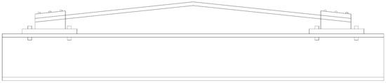
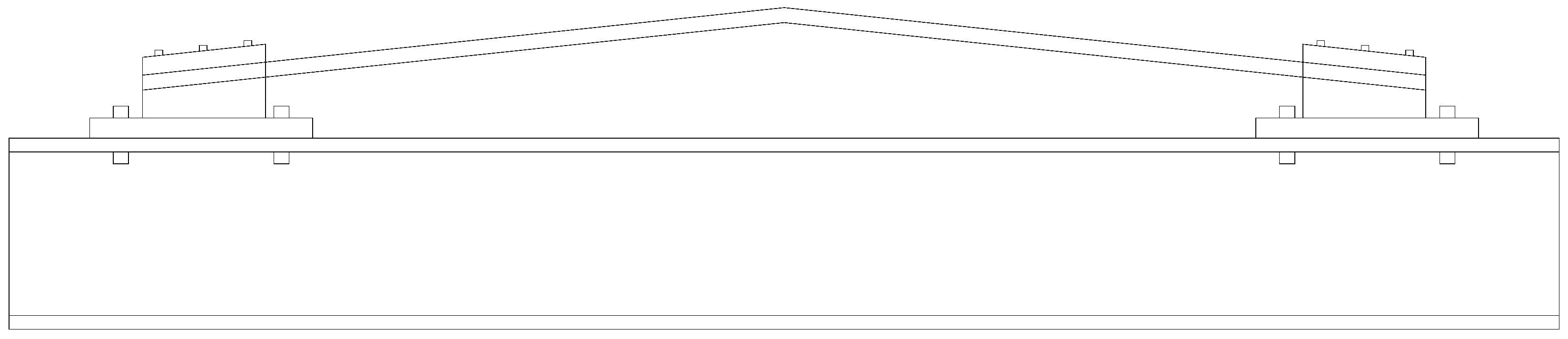
The toggle frame proposed by Williams [34] is shown in Figure 1. As noted earlier, this structure exhibits an instability phase under vertical loading, which results in an NS characteristic. Leveraging this load–displacement behavior, the toggle is proposed to be incorporated into a QZS isolator as an NS component. This section primarily investigates its vertical load–displacement relationship.
Figure 1.
Williams’ toggle frame on an I beam.
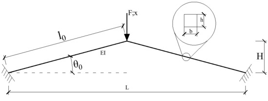
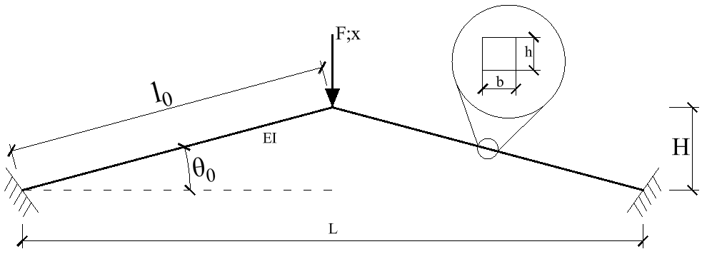
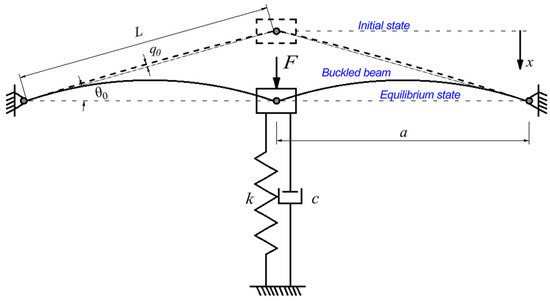
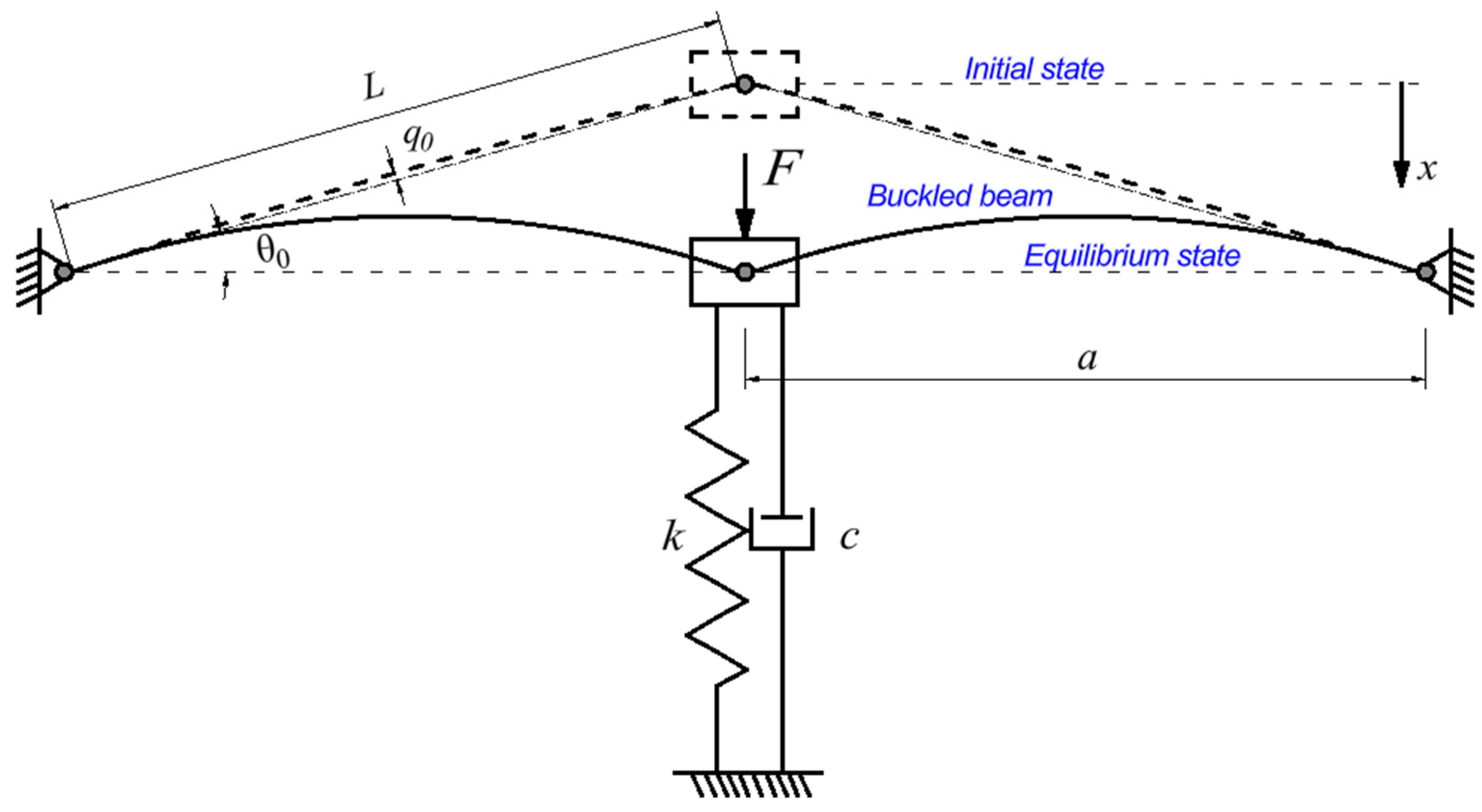
Figure 2 shows a schematic diagram of the toggle frame. The frame, which was initially straight, is bent at its center in order to form the apex of the toggle, then the length on the either side of the apex forms the members of the toggle. Both members have a rectangular cross-section and are fixed at their ends. The key geometric and material parameters are defined as follows: the cross-sectional width is , the height is , the span is , the elastic modulus is , the original member length is , the initial member angle with respect to the horizontal direction is , and the arch height (vertical distance from the apex to the horizontal line) is .
Figure 2.
Schematic diagram of the toggle frame.
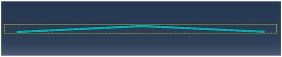
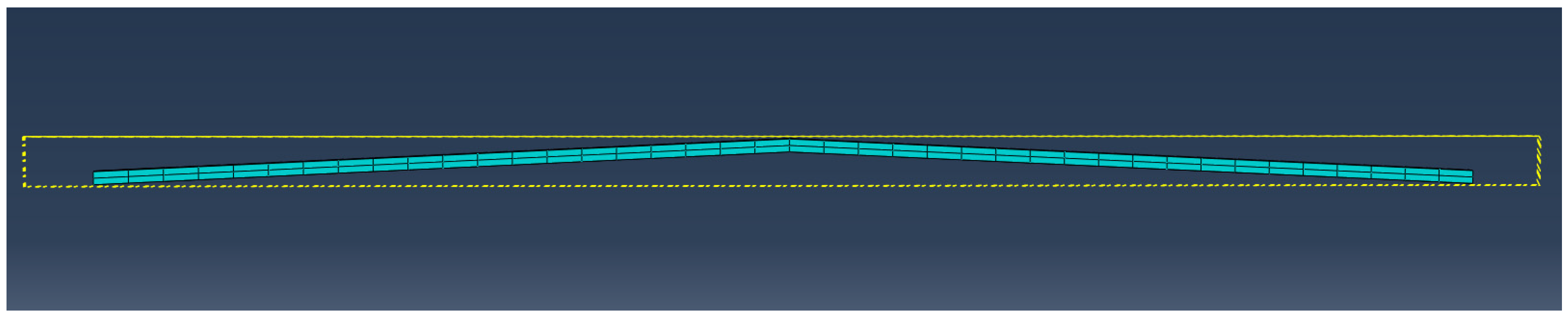
When the apex undergoes a vertical downward displacement x, the structure generates an upward restoring force . A series of FEM analyses are performed to simulate the loading process. The model, developed using ABAQUS, is shown in Figure 3. The toggle is meshed using the C3D8R cell (eight-node reduced-integral solid cell). In order to accurately capture the deformation, 10 layers of meshes are assigned along the thickness direction (perpendicular to the plane of the paper). Through the mesh convergence analysis, the amount of the length directional mesh layers of one member is determined to be 20 (under an approximate global size of 2.5). When the approximate size of the mesh is set to 3 and the change in reaction force is less than 1%, it can indicate that the mesh is converging. Two reference points are established directly on the outer sides of the left and right ends of the structure, which are constrained by “coupling” with the two ends, respectively. And the displacement and reaction force of the two reference points are output. Boundary conditions at the two reference points should be set as completely fixed. Displacement-controlled loads with varying eccentricities are applied at the apex to study the toggle’s static characteristics under conditions both with and without torsional deformation. The maximum length of time step is set as 0.001 to ensure that the computational error is within an acceptable range and the results are smooth.
Figure 3.
The model built in ABAQUS.
To investigate the influence of geometric parameters on the negative stiffness (NS) of a steel toggle frame, load–displacement curves are calculated for different cross-sectional sizes, height-to-span ratios (H/L) and eccentricities , and sensitivity analysis of cross-sectional size and H/L is provided.
According to elasticity theory, the flexural rigidity for a rectangular cross-section is given by
where is the width and is the height of the cross-section.
The torsional rigidity is [40]
where G is the shear modulus, and (with ) are the side length of the cross-section, is a shape-dependent factor, and
The effects of these geometric parameters on both bearing capacity and stiffness are nonlinear and manifest differently across the load–displacement curve. Equation (1) shows that the flexural rigidity varies independently with and . Meanwhile, the torsional rigidity is symmetrically influenced by and , as evident from Equations (2) and (3). Given that the cross-sectional dimensions a, b, and h exert decoupled influences on rigidity based on the above relationships, a single-factor design approach is adopted for the cross-sectional size. For the factor H/L, whose influence pattern is not fully determined a priori, a full factorial design is employed. The specific parameter values selected for this study are listed in Table 1.
Table 1.
Parameters adopted (unit: cm).
2.2. NS Characteristics and Parameter Influence Rules
2.2.1. NS Characteristics
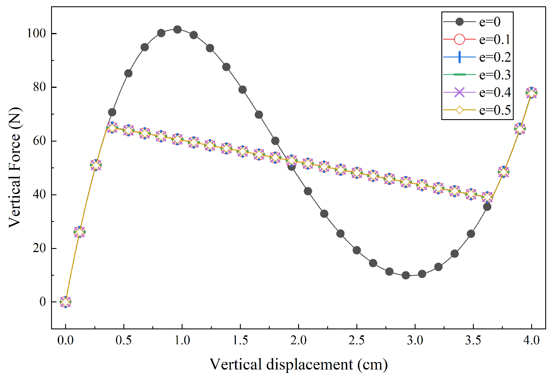
A specific toggle configuration is analyzed as an example, with the following parameters: total span = 1 m, arch height , and cross-section , modulus of elasticity . The resulting vertical load–displacement relationship is shown in Figure 4.
Figure 4.
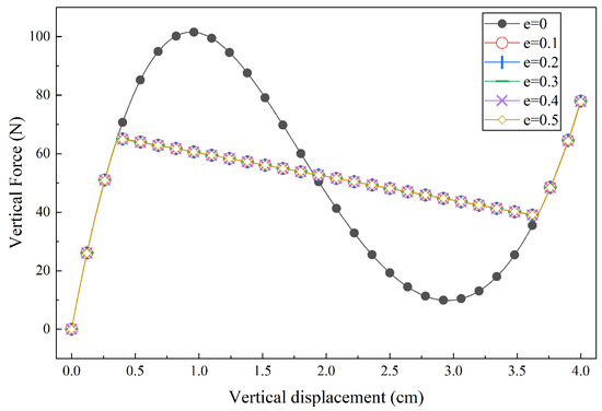
Force–displacement curve under different eccentricities.
As shown in Figure 4, the curve marked with black squares, which represents the load case without eccentricity (e = 0), is approximately cubic. In contrast, the curves for all eccentric load cases (e ≠ 0) are nearly coincident with each other. These coincident curves consist of three distinct segments: an approximately linear descending segment in the middle, and two segments at the ends that largely coincide with the black curve. This indicates that, once an eccentric load has been applied, the specific magnitude of the eccentricity has negligible influence on the overall shape of the load–displacement curve. Comparing the two situations reveals that eccentric loading induces flexural–torsional buckling. This buckling mode facilitates greater vertical displacement, resulting in a wider NS interval but a reduced absolute NS value. However, for a given vertical displacement, the limited degree of axial torsion associated with this buckling does not significantly alter the vertical reaction force. Consequently, provided that flexural–torsional buckling is triggered, the curve shape remains largely insensitive to the exact value of the eccentricity.
The approximate expression for the vertical load–displacement relationship without eccentricity can be written as
where , and are fitting parameters obtained by fitting the results of static simulation. The coefficients A0, B0, and C0 depend on the cross-sectional dimensions and H/L of the toggle frame. All other conditions being equal, the larger the coefficient A0, the greater the negative stiffness of the structure. And the coefficient d should always be 0.
The expression for approximate vertical stiffness can be obtained by differentiation:
When , attains its minimum. The corresponding displacement, , defines the equilibrium position. By shifting the coordinate origin to this equilibrium position, the above expressions are transformed into
The approximate piecewise expressions for the vertical load–displacement and stiffness–displacement relationships with eccentricity are given by
where is the slope of the linear descending segment, and are the -coordinate of its two endpoints. These two points can be obtained from simulation results or by making the two segments of the approximate piecewise function equal.
Because of the linear NS, does not have a distinct minimum value. Thus, any point of the NS segment can be chosen as the equilibrium position. For consistency, is also defined as the equilibrium position. The corresponding load–displacement and stiffness–displacement expressions for the eccentric case can be obtained by substituting Equations (8) and (9) into Equations (6) and (7)
where , .
The five situations with different eccentricities are fit in Figure 4 using the approximate piecewise expression shown in Equation (8). The fitting parameter and coefficient of adjusted determination and standard errors are shown in Table 2.
Table 2.
Fitting parameters derived from the simulations.
Table 2 shows that the for A0, B0, and C0, and for k and l are very close to 1, which indicates that the cubic and linear equations of the fitting expressions are of sufficiently good quality. In addition, the standard errors of A0, B0, and C0 are small and within an acceptable range, indicating that the cubic fitting function is reasonable. By comparing the changes in the parameters obtained from these five situations, it can be concluded that once flexural–torsional buckling occurs, the changes caused by eccentricity are small. Therefore, the following sections will be limited to discussing whether flexural–torsional buckling occurs.
2.2.2. Effect of Section Width
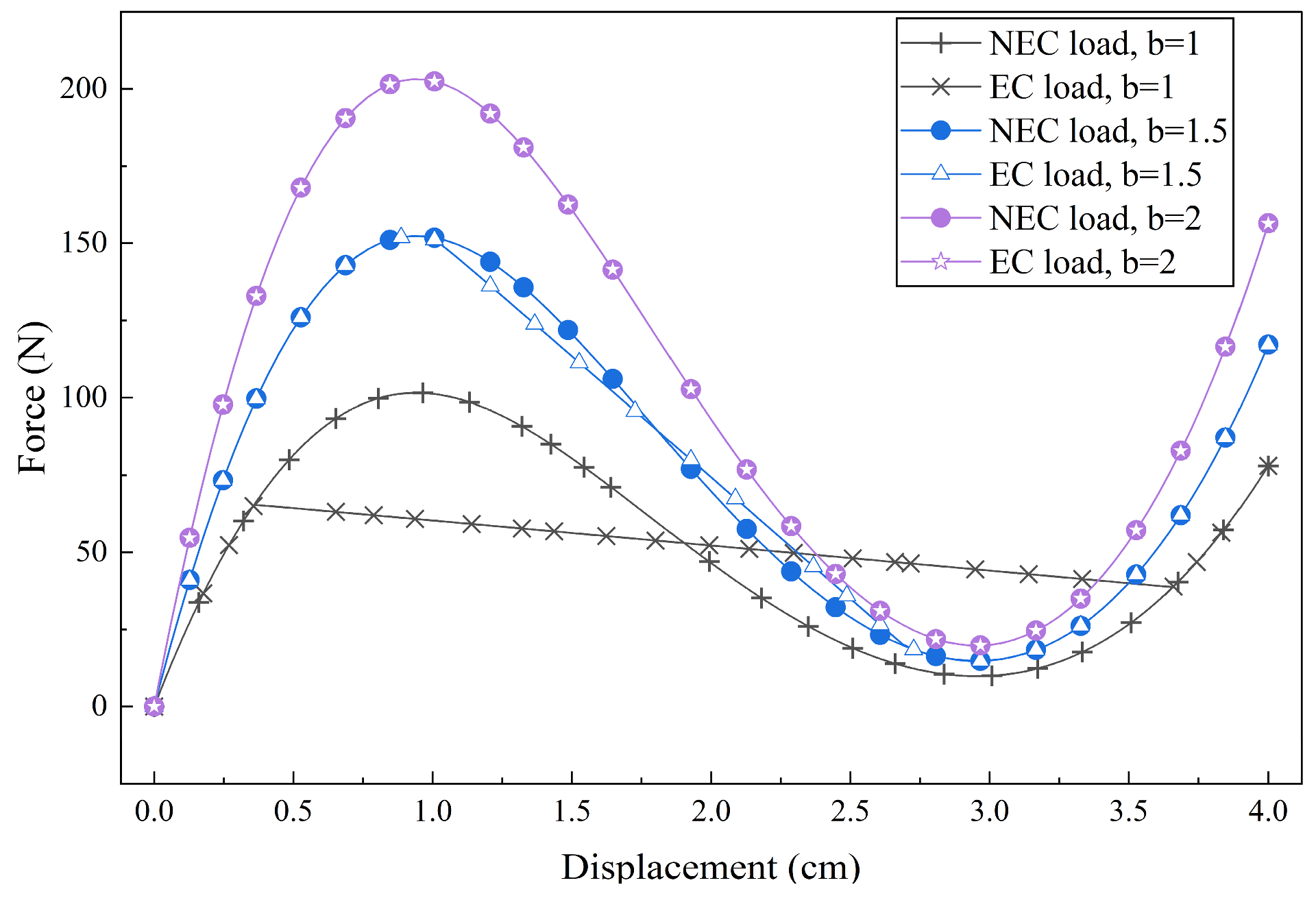
For a fixed height-to-span ratios as 2.5:100, the vertical load–displacement relationships for different cross-sectional widths are simulated, as shown in Figure 5.
Figure 5.
Load–displacement curves with different section widths under non-eccentric (NEC) and eccentric (EC) load.
As the width gradually increases, the peak load-bearing capacity of the toggle and, simultaneously, the absolute value of its NS increases. The enhanced flexural rigidity of the cross-section with increased width, as quantified in Equation (1), leads to a higher peak load-bearing capacity within the same deformation. And this also means there will be a higher rate of change in restoring force and a larger stiffness. However, under eccentric loading, the influence of torsional deformation on both the load-bearing capacity and the extent of the NS segment that resulted from flexural–torsional buckling diminishes and eventually vanishes. This occurs because the increased width enhances torsional rigidity (Equation (2)), leading to smaller torsional deformation under the same vertical load, which promotes a shift towards simple flexural buckling and makes torsional instability more difficult to induce. As a result, the overall impact of torsional deformation on the load-bearing capacity is generally reduced.
Fitting these curves under eccentric load by Equations (4) and (8), the fitting parameters and the width of linear intervals are shown in Table 3. The data from top to bottom in the table represents the increasing section width.
Table 3.
Fitting parameters derived from the simulations with different section widths.
It can be found that in the third row, is smaller than , with no width of linear interval (because it is unable to solve for more than one solution by making the two segments equal), meaning that the cubic fitting expression is more appropriate than the linear one and the linear character of NS has disappeared. This confirms the statement in the previous text that the enhanced torsional bearing capacity makes it more difficult for flexural–torsional effects to occur. For the slope and the linear interval width , the sensitivity indicators are defined as and , where and is the increment of the section width. Then they can be calculated as , . As the cross-sectional width increases from 1 cm to 1.5 cm, the slope increased by 8.6 times, but the width of linear interval decreased by 0.48 times. Based on the above analysis, a widened cross-section can provide a greater NS, but in order to preserve the linear characteristics, the width of the cross-section must be limited within a reasonable range. For instance, in the studied example, the width cannot exceed two.
2.2.3. Effect of Section Height
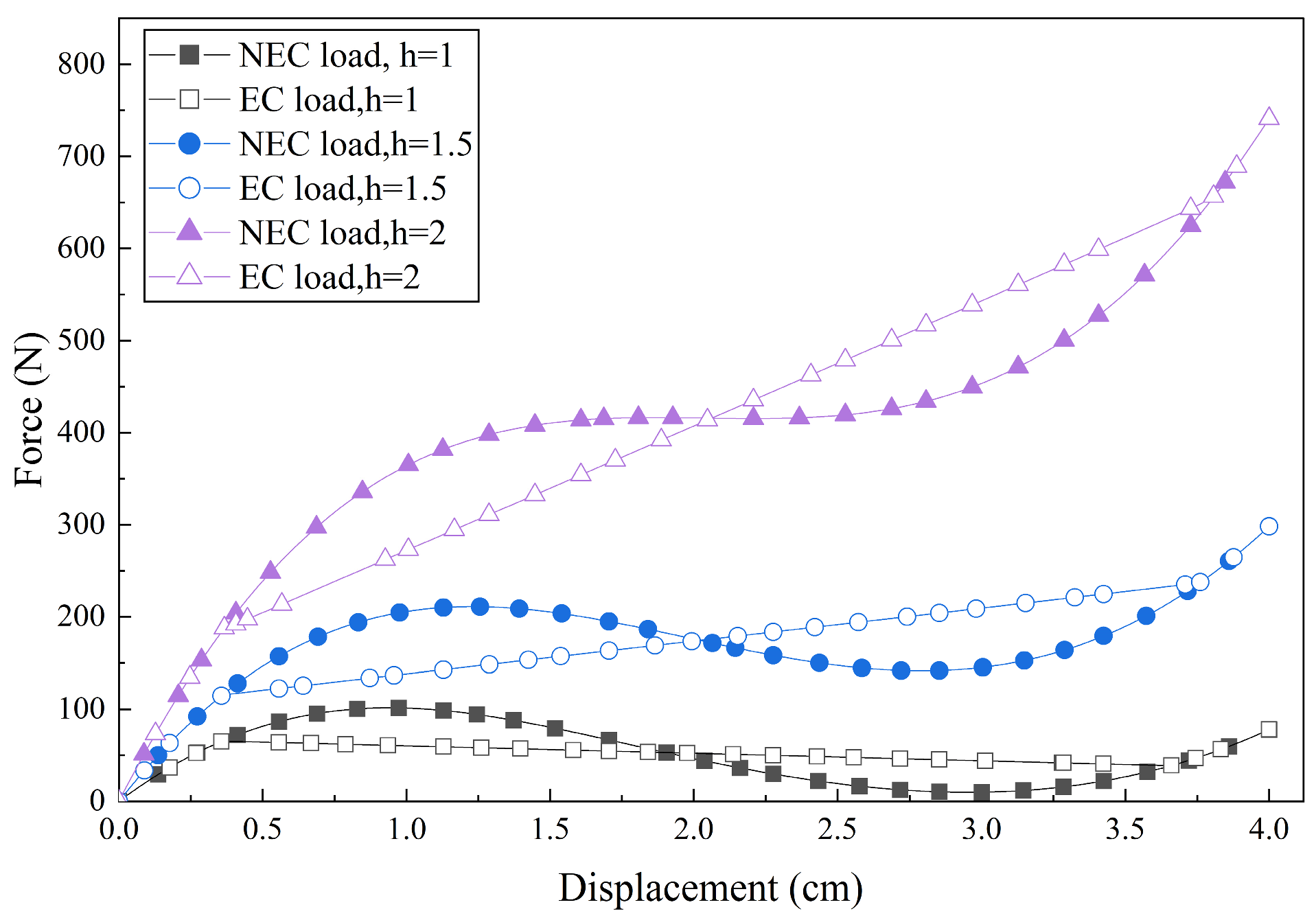
For a fixed height-to-span ratio of 2.5:100, the vertical load–displacement relationships for different cross-section heights are simulated, as shown in Figure 6.
Figure 6.
Load–displacement curves with different section heights.
As the height increases, the peak bearing capacity increases more sharply, while the NS characteristic diminishes. This is because increasing the height enhances torsional rigidity to the same degree as increasing the width, but it improves flexural rigidity much more substantially. As a consequence, a larger load is required to achieve the same displacement, making it more difficult for the toggle to undergo a reduction in its overall load-bearing capacity. However, torsional rigidity increases linearly, whereas flexural rigidity increases cubically. This makes flexural buckling less likely to occur under non-eccentric load, but increases the likelihood of torsional buckling under eccentric load. Moreover, load eccentricity still alters the shape of the curves, and the extent of this alteration (quantified by the area between the eccentric and non-eccentric curves) increases with height. However, because the descending segment of the load-bearing capacity curve gradually disappears, torsional buckling becomes less effective at generating a distinct NS characteristic.
Fitting these curves under eccentric load by Equations (4) and (8), the fitting parameters and the width of linear intervals are shown in Table 4. The data from top to bottom in the table represents the increasing height of the section.
Table 4.
Fitting parameters derived from the simulations with different section heights.
Using the same method, the sensitivity indicators can be derived as , . As the cross-sectional height increases from 1 cm to 1.5 cm, the slope increases from negative to positive by 5.4 times, and the width of linear interval increases by 0.03 times. Thus, although increasing the cross-sectional height has a greater influence on the slope, its tendency to make the slope positive implies that caution should be exercised when considering height increments in the design.
2.2.4. Effect of Height-to-Span Ratio
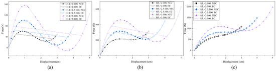
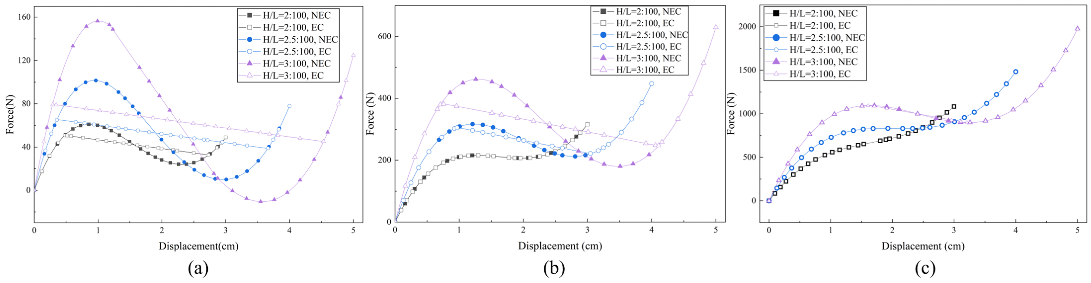
For several rectangular cross-section sizes, the vertical load–displacement relationships for different height-to-span ratios are simulated, as shown in Figure 7.
Figure 7.
Load–displacement curves with different height-to-span ratios (a) under (b) and (c) .
As the height-to-span ratio increases, several trends are observed: (1) the peak load-bearing capacity of the toggle increases; (2) the magnitude of NS increases; (3) the influence of torsional deformation on the curve shape becomes more pronounced; and (4) the NS interval widens. This can be attributed to the fact that a higher height-to-span ratio results in a larger axial force component under the same vertical deformation, which enhances the overall restoring force. Furthermore, the increased axial force also promotes the development of geometric nonlinearity and instability, making the negative stiffness behavior more pronounced as the height-to-span ratio increases.
Fitting these curves under eccentric load by Equations (4) and (8), the fitting parameters and the width of NS intervals are shown in Table 5.
Table 5.
Fitting parameters derived from the simulations with different H/L and section sizes.
Using the same method, the sensitivity indicators can be derived as , . It can be found that slope changes very little with H/L at the same section size, while the width of NS shows an obvious increase as H/L increases.
Comparing the effect of section width and height-to span ratio H/L, the linear NS value is more sensitive to section width than H/L, while the width of NS interval is more sensitive to H/L. All other conditions being equal, to obtain a greater NS value, we need to make the cross-section wider, and to obtain a wider NS interval, we need to make the H/L ratio greater. In practical engineering applications, geometric configurations that yield wider NS intervals and proper absolute NS values should be selected, provided that the required load-bearing capacity and elastic range are maintained.
2.3. Static Analysis of Proposed QZS System
Figure 8 shows a schematic of the proposed QZS vibration isolation system. The positive stiffness (PS) is supported by a vertical spring system with a total stiffness of , and the NS is provided by the toggle frame described previously. The isolated object has a mass and reaches the equilibrium position under gravity.
Figure 8.
Sketch of the proposed QZS vibration isolation system.
Taking the equilibrium position as the coordinate origin, the restoring force produced by vertical displacement is
The stiffness of the system is
Substituting the QZS condition, , into Equation (13) yields the condition for the system to achieve QZS:
When this condition is satisfied, the system exhibits quasi-zero stiffness around , meaning that the overall stiffness is nearly zero within a small displacement range. This effectively lowers the natural frequency of the system and extends the frequency range for effective vibration isolation, which is particularly advantageous for isolating low-frequency vibrations. In the case of an eccentric load, Equation (14) transforms into
Equation (13) indicates that incorporating NS component reduces the effective linear stiffness of the system. Within a specific displacement interval, this effective stiffness becomes lower than the vertical spring stiffness . Consequently, the natural frequency of the linearized system is reduced, and the frequency range for effective vibration isolation is broadened.
3. Dynamic Analysis
3.1. Dynamic Modeling
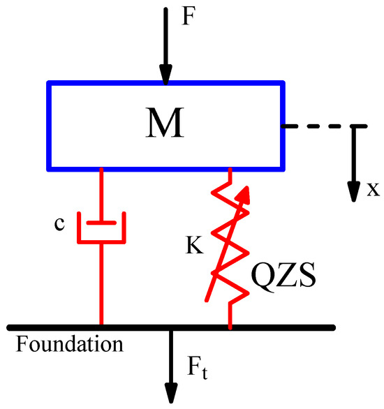
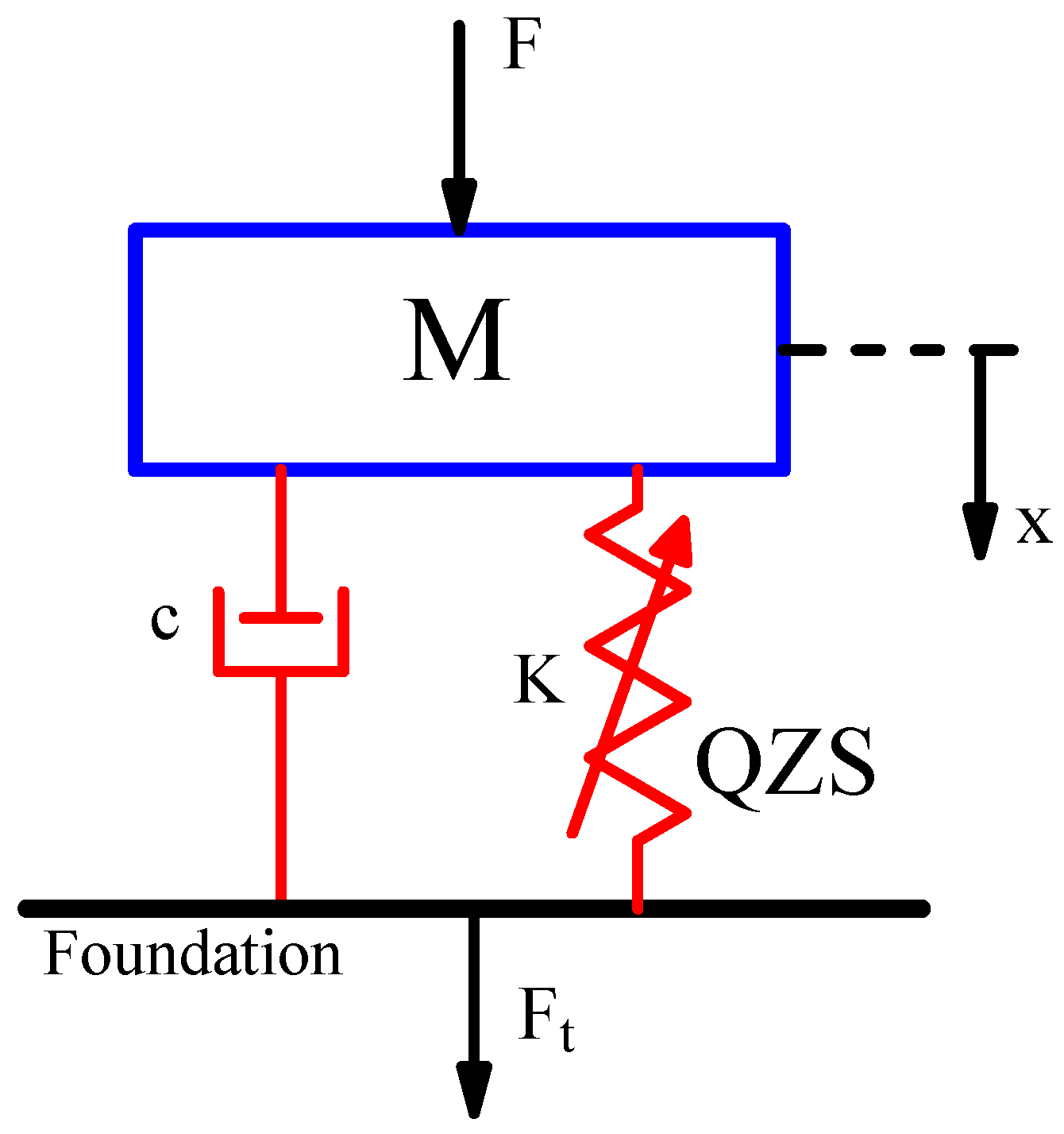
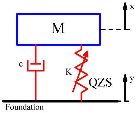
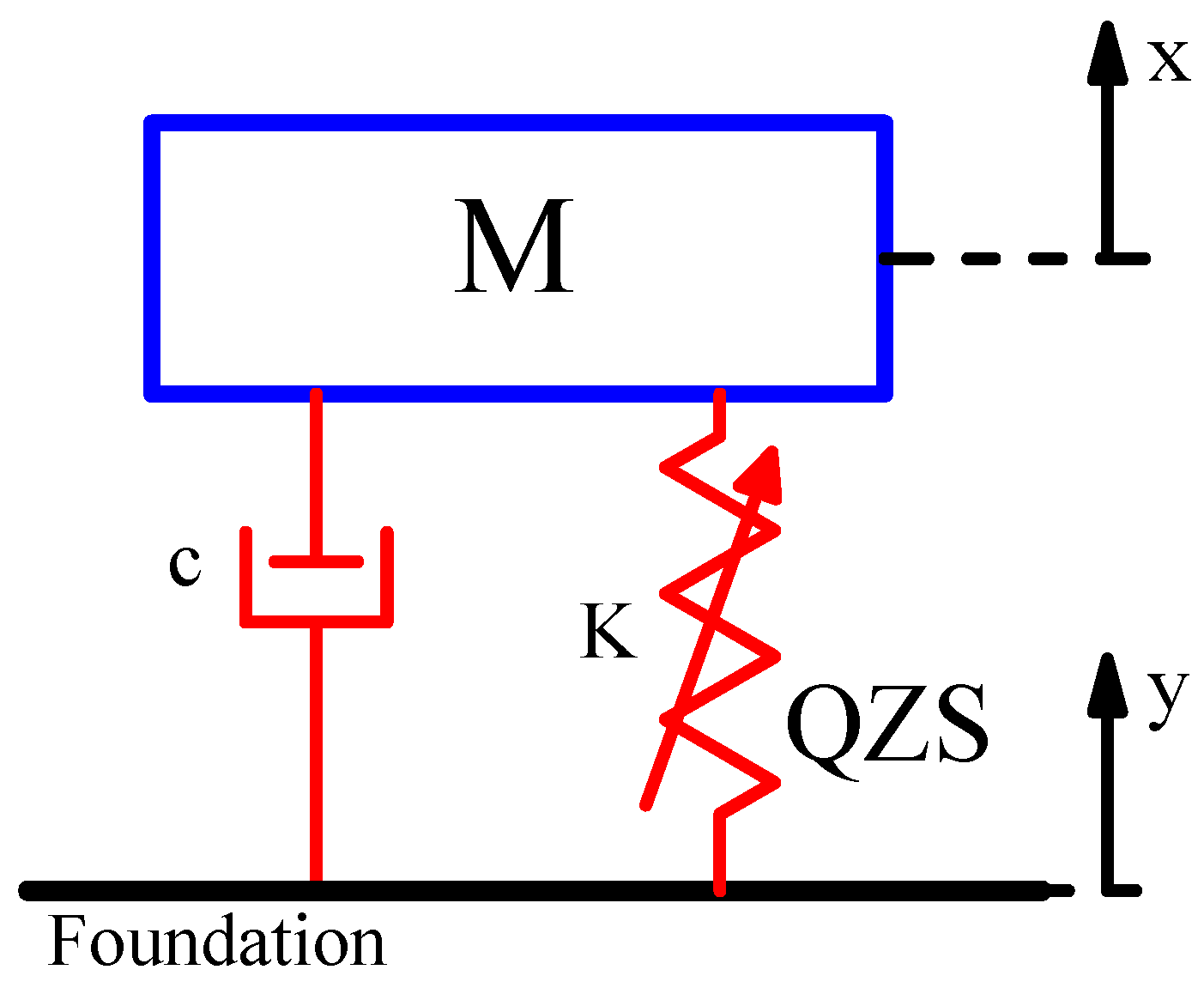
When the vibration source is force excitation from the isolated object , the foundation is isolated from through the isolation system to reduce the vibration transmitted to the foundation, as shown in Figure 9. The QZS part is the system described in Section 2.3, and the system is in the equilibrium position under gravity in the initial state. The damping part can be generated by the system itself or can be an additional damper. A first-order harmonic balance method (HBM) is used to solve the system.
Figure 9.
Diagram of a QZS system under force excitation.
The system undergoes a displacement due to a harmonic force excitation . Combining Equation (12), the equation of motion for the system is derived as
where and .
By introducing the following dimensionless parameters
where is called the frequency ratio of excitation to natural frequency.
Equation (16) can be rewritten as
When the vibration source is a displacement excitation applied at the foundation, given by , the resulting displacement of the mass is . A schematic of the QZS system under displacement excitation is shown in Figure 10.
Figure 10.
Diagram of a QZS system under displacement excitation.
Defining the relative displacement of the system as , the motion equation can be expressed as
The dimensionless form of Equation (18) is
where and .
For the convenience of the solution, Equations (17) and (19) can be cast into the unified form:
For a harmonic force excitation, we have . For a harmonic displacement excitation, we have . According to HBM, the steady-state response of the system can be estimated as:
where and represent the response amplitude and phase angle, respectively.
Substituting Equation (21) for in Equation (20) yields
where
and
Ignoring the higher-order terms and equating the coefficients of and on both side yields
By squaring both sides of Equation (25) and eliminating , we obtain
This is the amplitude–frequency characteristic equation for the system under harmonic excitation without eccentricity. Two positive solutions of Equation (26) are
For an eccentric excitation, assuming the system operates within the QZS segment, Equation (20) reduces to
Substituting Equation (21) into Equation (29) gives
Substituting Equation (24) into Equation (30) and equating the coefficients of and on both sides leads to
By squaring both sides of Equation (31) and eliminating , we obtain
This is the amplitude–frequency characteristic equation for the system under harmonic excitation with eccentricity. Two positive solutions of Equation (32) are
3.2. Vibration Isolation Analysis
3.2.1. Amplitude–Frequency Characteristic Under Force Excitation
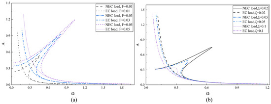
Equations (27) and (33) indicate that the amplitude–frequency characteristic is influenced by the excitation amplitude , the damping ratio , the linear parameter , and the nonlinear parameter . Under ideal QZS condition, linear parameter . Furthermore, Equation (33) shows that for an eccentric load, the characteristic is independent of the nonlinear parameter . This section focuses on analyzing the effects of the excitation amplitude and damping ratio. As shown in Figure 11, the amplitude–frequency curves are obtained by substituting different parameter values into the solutions of Equations (26) and (32).
Figure 11.
Amplitude–frequency under force excitation with (a) () (b) ().
A jump phenomenon, indicating an unstable response interval, is observed in the non-eccentric load case in Figure 11, while there is no jump phenomenon in the response of eccentric loads, indicating that the toggle frame QZS system can provide stable response under flexural–torsional buckling. Physically, the jump phenomenon arises from the multivalued nature of the amplitude–frequency response in nonlinear systems. In the non-eccentric load case, the system exhibits hardening stiffness behavior due to its cubic nonlinearity. This is the characteristic of nonlinear stiffness and occurs within a frequency range where multiple steady-state amplitudes are possible for a single frequency. In Figure 11a, the response amplitude, the maximum of the response amplitude (for the non-eccentric case), and the corresponding jump frequency all increase with the excitation amplitude. In Figure 11b, as the damping ratio increases, the response amplitude, its maximum value (non-eccentric case), and the corresponding jump frequency all gradually decrease. Concurrently, the jump phenomenon diminishes and the system nonlinearity weakens.
3.2.2. Force Transmissibility and Influence of Primary Parameters
Under harmonic non-eccentric force excitation, the dimensionless force transmitted through the isolation system can be derived from Figure 9 as
Substituting the system response for in Equation (35) yields
The amplitude of the force transmitted to the foundation can be estimated using the same method described in Section 3.1.
Thus, the transmissibility is
Following the same procedure, the transmissibility for the system with an eccentric load is obtained as
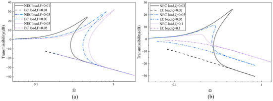
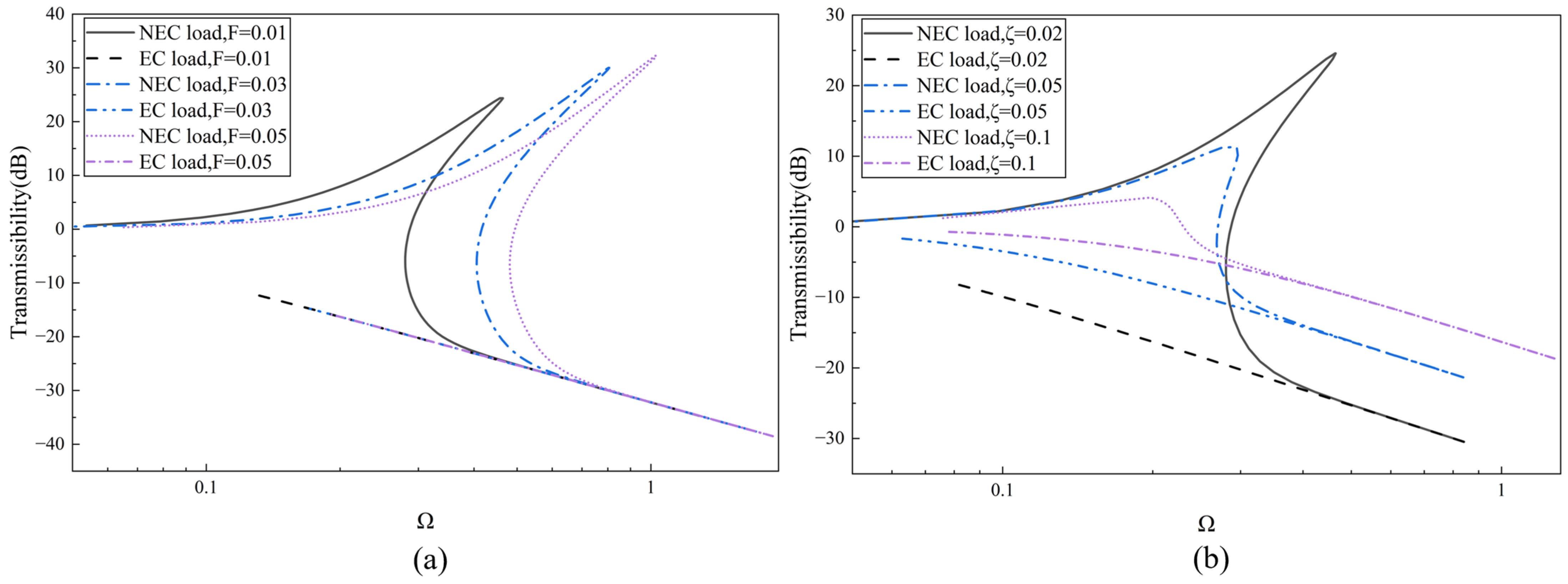
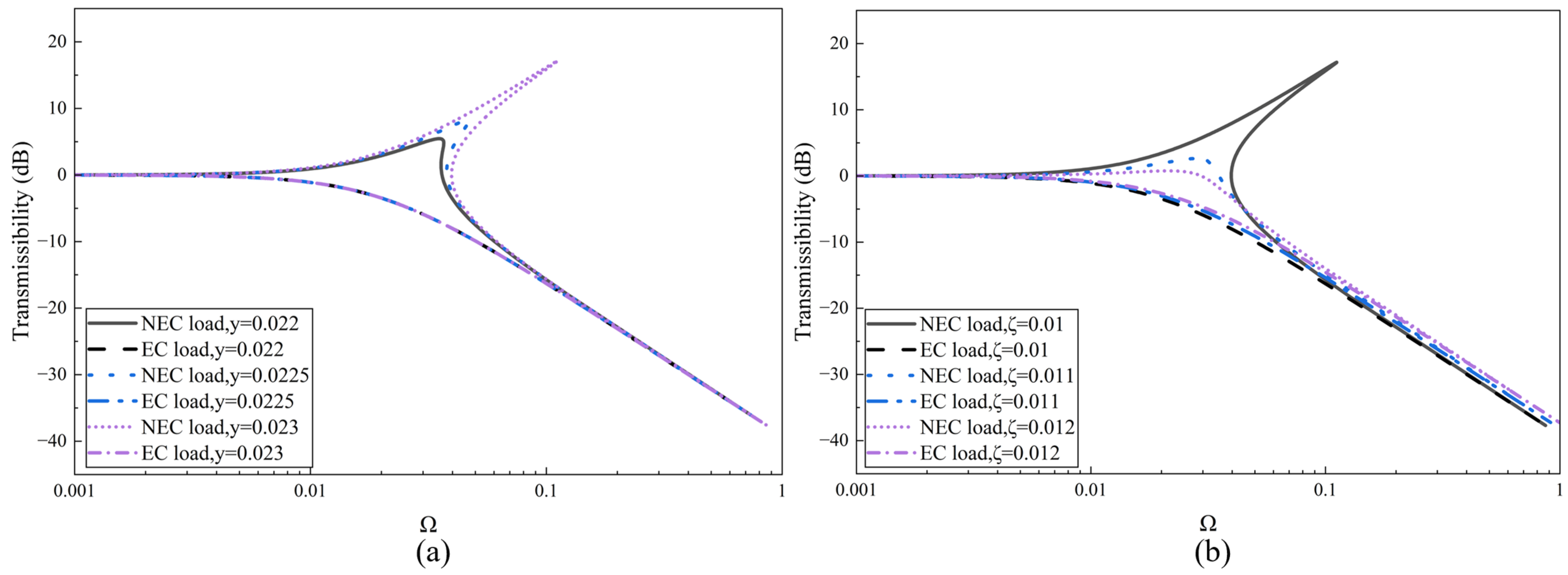
By substituting different values of excitation amplitudes and damping ratio, the transmissibility–frequency curves are derived, as shown in Figure 12.
Figure 12.
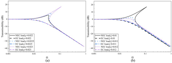
Transmissibility under force excitation with (a) () (b) ().
There is also a jumping phenomenon in the transmissibility curve of the system without eccentric load, and the stability of the non-eccentric load is similar to that in the amplitude–frequency response. In Figure 12a, as the excitation amplitude increases, the transmissibility curve for the non-eccentric case shifts toward higher frequencies, and both the initial isolation frequency and the peak transmissibility increase. In contrast, the transmissibility for the eccentric load case remains negative and is unaffected by the excitation amplitude. In Figure 12b, an increase in the damping ratio causes the initial isolation frequency and peak transmissibility for the non-eccentric case to decrease, while the system nonlinearity gradually diminishes; for the eccentric load case, the transmissibility increases but remains negative.
3.2.3. Amplitude–Frequency Characteristic Under Displacement Excitation
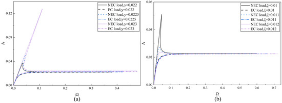
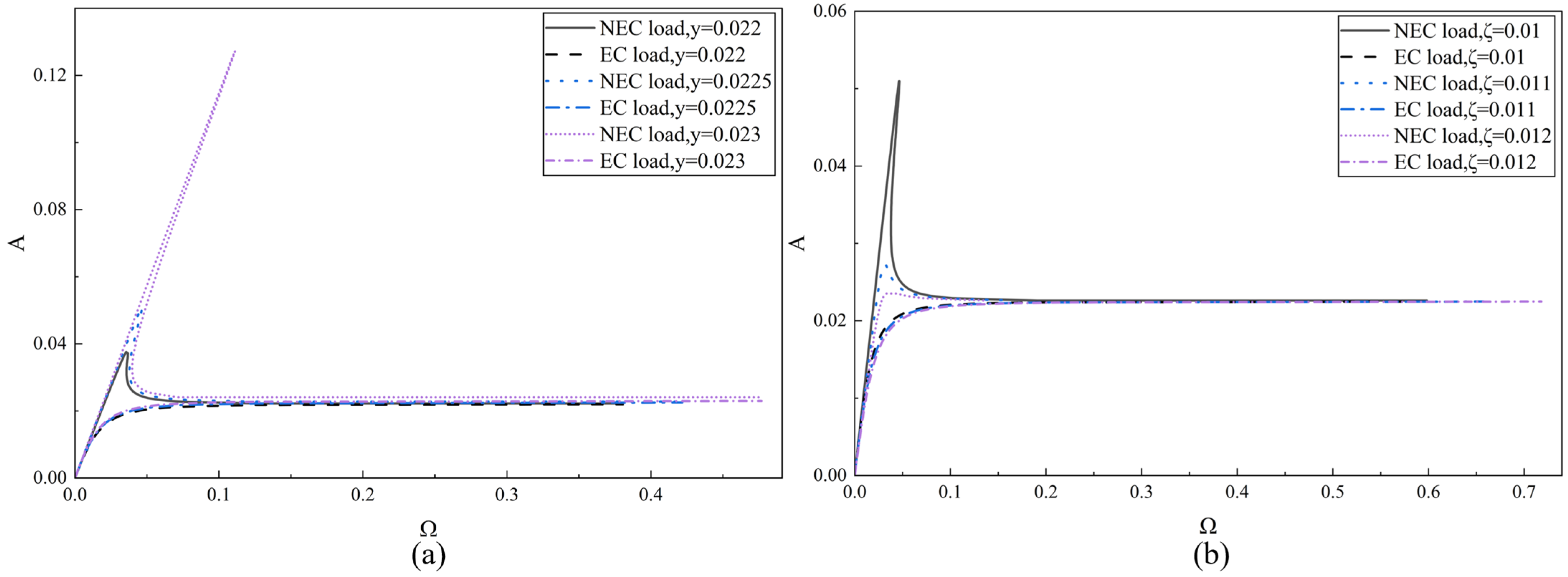
As shown in Figure 13, the amplitude–frequency curves are obtained by substituting different parameters values into Equations (28) and (34).
Figure 13.
Amplitude–frequency under displacement excitation with (a) () (b) ().
In Figure 13a, for the system without an eccentric load, the response amplitude, its maximum value, and the corresponding jump frequency all increase with the displacement excitation amplitude. A similar but less pronounced increasing trend is observed for the system with an eccentric load. In Figure 13b, as the damping ratio increases, the response amplitude, its maximum value (for the non-eccentric case), and the system nonlinearity all gradually diminish.
3.2.4. Displacement Transmissibility and Influence of Primary Parameters
From the relation , the dimensionless displacement of the mass is . Substituting the foundation displacement and relative displacement from Equation (21) yields
Then the displacement transmissibility for the system without eccentricity can be derived as
where
For the eccentric load case, the expression retains the same form as Equation (41), while becomes
By substituting different values of excitation amplitude and damping ratio, the transmissibility curves are obtained, as shown in Figure 14.
Figure 14.
Transmissibility under displacement excitation with (a) () (b) ().
In Figure 14a, as the excitation amplitude increases, the nonlinearity becomes more pronounced, and both the initial isolation frequency and the peak transmissibility increase. The transmissibility for the eccentric load case, however, remains unaffected by the excitation amplitude. In Figure 14b, an increase in the damping ratio leads to a decrease in the initial isolation frequency, peak transmissibility, and corresponding jump frequency for the non-eccentric system, while the system nonlinearity gradually diminishes. For the eccentric load case, the transmissibility increases but remains negative.
3.3. Numerical Analysis
3.3.1. Dynamic Model Validation
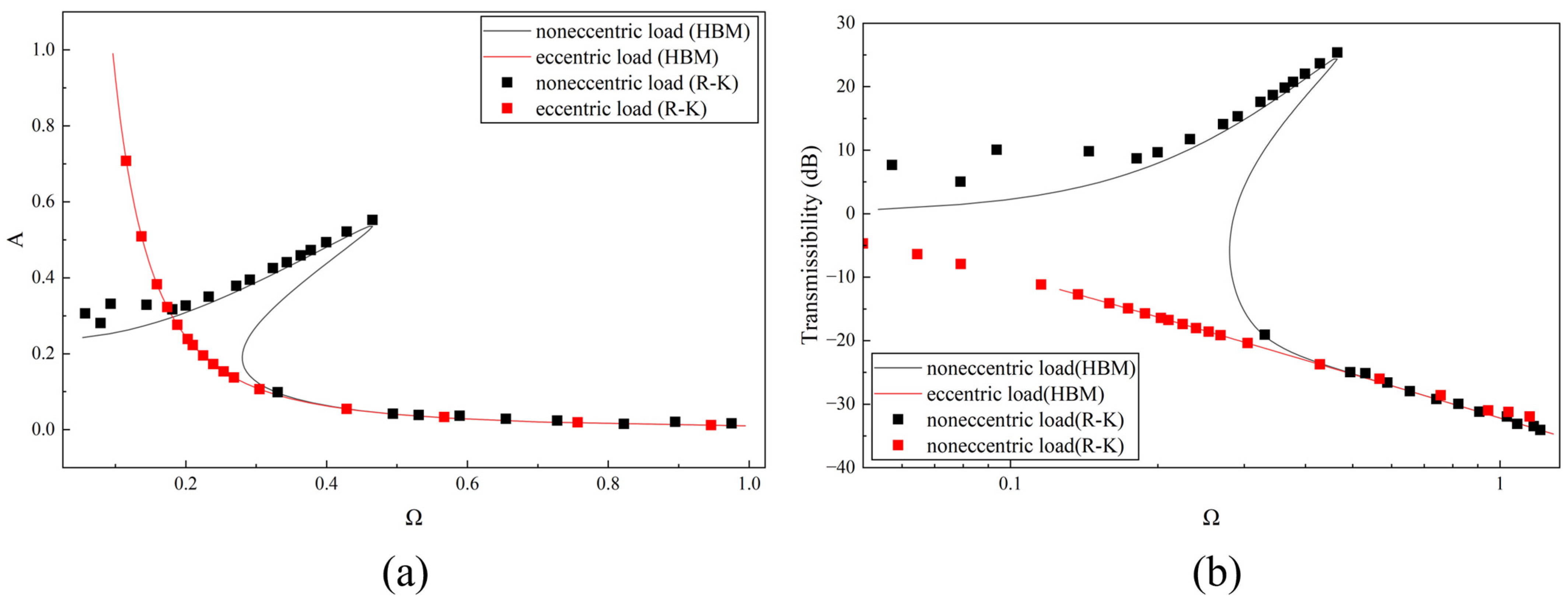
In order to validate the dynamic model and the analytical solution obtained by HBM, The Runge–Kutta (R-K) method is employed, and the comparison is shown in Figure 15.
Figure 15.
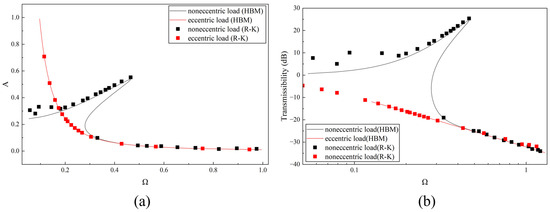
Comparison between R-K numerical solutions and HBM analytical solutions (, ). (a) Amplitude–frequency response. (b) Force transmissibility. The lines: analytical solutions obtained by HBM; the dots: numerical solutions obtained by Runge–Kutta method.
It can be seen that the trends of the HBM and R-K solutions coincide. Since the first-order HBM is used, the higher-order response and transmissibility at low frequencies (lower than 0.2) of non-eccentric load cannot be predicted with high accuracy. However, the numerical and analytical solutions are in exact agreement at all frequencies of eccentric load and at high frequencies of non-eccentric load. In Figure 15b, because of the small errors being amplified by higher-order terms in Equation (35), the coincidence degree at low frequencies of transmissibility is weaker than the response in Figure 15a. Generally, the analytical solutions based on first-order HBM can predict the response and the force transmissibility of the proposed QZS system. Future work could further strengthen these findings through experimental validation, which would help to fully assess the practical performance of the system.
3.3.2. Bifurcation Analysis
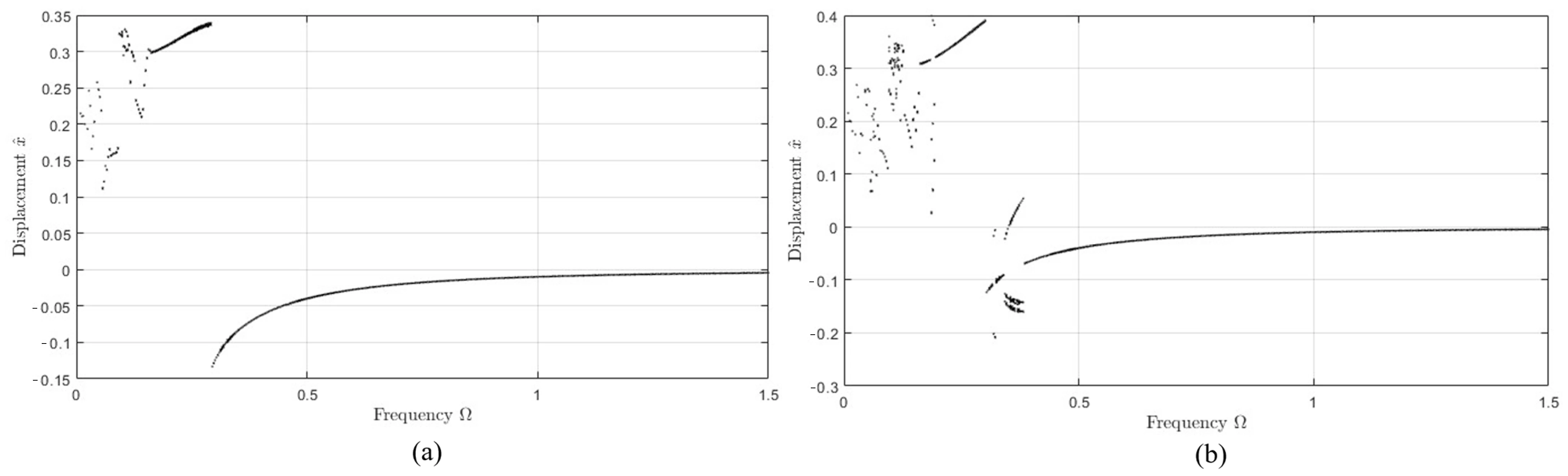
The jump phenomenon of the non-eccentric load case indicates that the motion may be unstable, and the isolator may generate the bifurcation and even chaotic motion. The complicated dynamic response should be avoided during the design of the toggle frame isolator. The dynamic response mode of the isolator will change with system parameters and initial conditions .
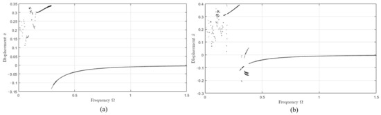
Figure 16 shows a bifurcation diagram with respect to the frequency ratio , where two bifurcation modes in the range of are illustrated, with the initial condition . The dimensionless displacement in Figure 16 is the system’s response displacement at the Poincaré section of , which is obtained by using the R-K method.
Figure 16.
Different bifurcation modes under (a) , (b) , .
In Figure 16, there are two bifurcation modes caused by different degrees of nonlinearity. Figure 16a illustrates the system with a lower nonlinear degree, and shows chaotic motion during a low-frequency ratio of ; Figure 16b represents the system with a higher nonlinear degree, and there is not only chaotic motion during a low-frequency ratio of , but also a double-periodic motion during a medium-frequency ratio of , and there is a narrow stable interval between the two bifurcation. As the frequency ratio increases, in both cases gradually approaches zero and no longer bifurcates. It should be noticed that the bifurcation mode also transforms between the two cases under different initial conditions.
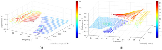
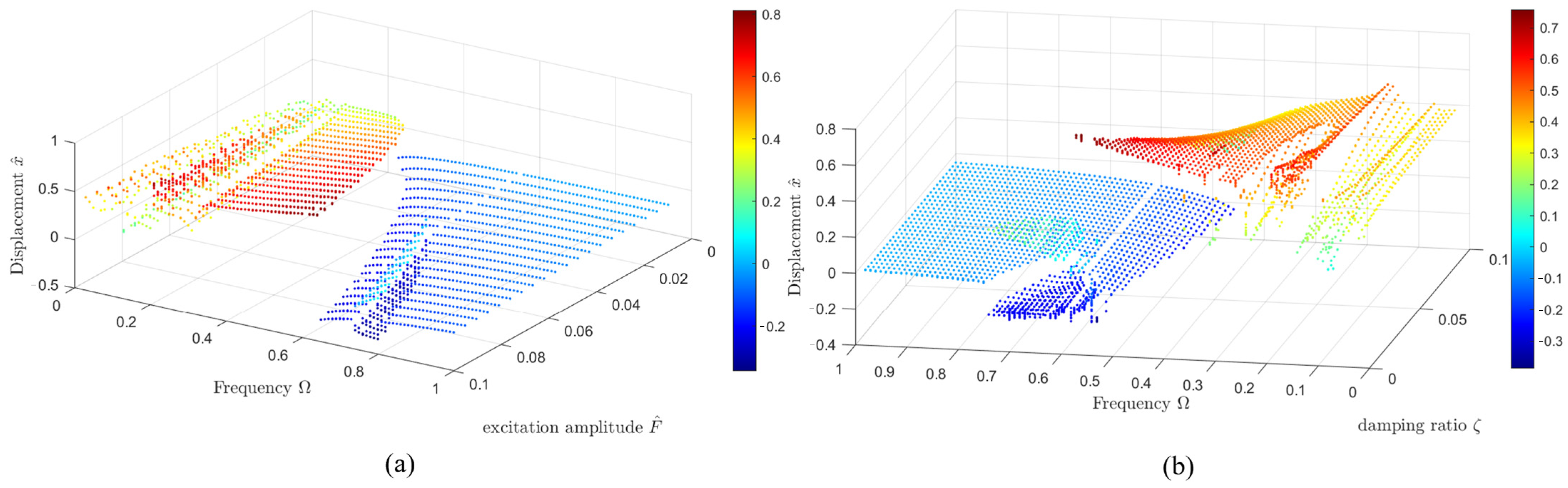
Figure 17 shows the trends of the bifurcation in the range of (a) with a fixed damping ratio and initial condition ; (b) with a fixed excitation amplitude and initial condition . The increase in excitation amplitude leads to the increase in the nonlinear degree. As a result, in Figure 17a, it can be found that as increases, the frequency range of bifurcation is widened, and the medium-frequency bifurcation appears and is broadened. Figure 17b shows the bifurcation when the damping ratio changes. The increasing damping ratio reduces the nonlinear degree of the system so that the medium-frequency bifurcation gradually disappears, and the low-frequency bifurcation narrows its interval and then disappears.
Figure 17.
Trend of the bifurcation caused by (a) excitation amplitude ; (b) damping ratio .
Due to the complex nonlinear dynamic behaviors of the toggle frame isolator during the low-frequency ratio shown in Figure 17, the system is suggested to be combined with a higher damping ratio to avoid bifurcation or use at a higher-frequency ratio to obtain an excepted isolation performance.
4. Comparison with Euler Buckling Model
Liu et al. proposed a well-known QZS isolator based on buckled beams as a negative stiffness corrector [15], and carried out a further theoretical and experimental study [41,42]. Figure 18 illustrates their NS components based on the Euler model.
Figure 18.
NS components based on buckled beams.
In this system, two beams are deployed obliquely with one end hinged together to provide NS for the system. Under the force , the beams are bent and kept in a flexural buckled state, and the system will generate vertical displacement . The dimensionless force–displacement relationship of the NS component is
where is the dimensionless force, ; is the dimensionless displacement, and , ; is the dimensionless initial imperfection of the beams; and . And the dimensionless stiffness can be derived by differentiation.
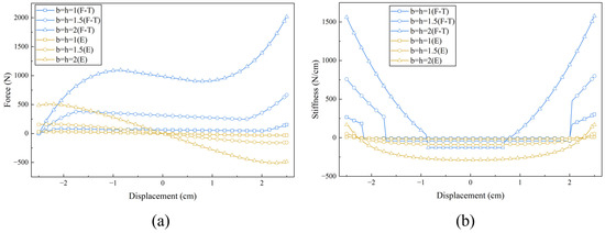
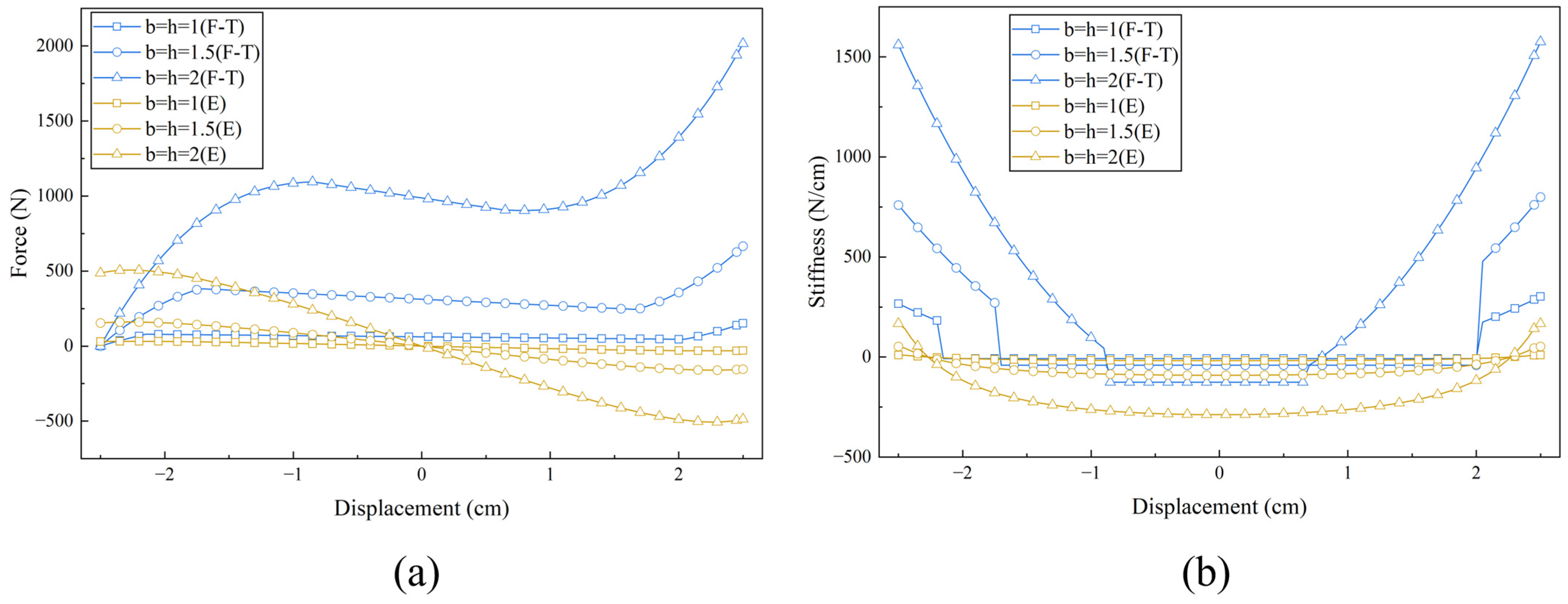
Consider that steel rods share the same parameters in Table 1 with the H/L ratio of 3%. The Euler buckled beam and the proposed toggle frame are applied to this rod, respectively. The vertical load–displacement and stiffness–displacement curves of the Euler buckling model are derived by substituting the relevant material and geometric parameters into Equation (44) and its differentiation. Use the equilibrium position as the origin to compare these curves, as shown in Figure 19.
Figure 19.
Comparison of the Euler buckling beam and the proposed model: (a) displacement; (b) stiffness.
In Figure 19a, the Euler buckled beam exhibits zero load-bearing capacity at its equilibrium position, while the proposed model has a certain static bearing capacity at equilibrium position and the capacity increases greatly with the cross-section size. With the designed size, it can be found that the maximum static bearing capacity at the equilibrium position is about 1000 N. In Figure 19b, it can be observed that the NS of both of the two models increases with cross-section size, and the width of NS decreases with the size. More importantly, the NS of the Euler buckling model is nonlinear, while the flexural–torsional buckling model can provide an approximately linear negative stiffness, thereby avoiding the instability issues associated with the nonlinear stiffness of ordinary QZS models.
5. Conclusions
This study presents a novel QZS isolator incorporating a toggle frame that exploits flexural–torsional buckling. The structure [30] and the buckling mode [39] are rarely considered when designing QZS systems. Compared with equivalent linear isolators [39], the toggle frame QZS isolator provides a wider isolation frequency range and better isolation performance under eccentric harmonic excitation. Its static and dynamic characteristics are thoroughly analyzed. The main conclusions are as follows:
- (1)
- For the novel quasi-zero-stiffness isolator, the force–displacement curve under zero eccentricity is approximately cubic. When a certain eccentricity is applied, the descending segment of the curve becomes approximately linear.
- (2)
- Increasing the cross-sectional width raises both the peak load capacity and the absolute value of NS, while reducing the influence of torsional deformation on load capacity. A higher cross-section significantly increases the peak load capacity but gradually diminishes the NS characteristics. A larger height-to-span ratio enhances the peak load capacity and NS behavior, makes the effect of torsional deformation on the curve shape more pronounced, and widens the NS range.
- (3)
- In the non-eccentric load system, the response amplitude, the maximum response value and its corresponding jump frequency, the peak force transmissibility, and the initial vibration isolation frequency all increase with the excitation amplitude. In contrast, a higher damping ratio reduces system nonlinearity and decreases all these dynamic response parameters.
- (4)
- For the eccentric load system, the negative stiffness is linear, eliminating the jump phenomenon. The response amplitude increases with excitation amplitude and decreases with damping ratio. Both force and displacement transmissibility remain negative and are insensitive to excitation amplitude, but increase with damping ratio.
- (5)
- Compared with the Euler buckled beam [15], the proposed isolator offers a greater load-bearing capacity within a small displacement range and a linear NS, thereby avoiding the instability issues associated with the nonlinear stiffness of ordinary QZS models.
The proposed toggle frame QZS isolator introduces a new principle that can be used to provide NS and a new structure can be combined into QZS systems. Further research can consider seeking more optimized bending torsional instability structures and materials used in structural design, such as changing the constraint conditions at both ends, new structures for flexural–torsional buckling, and using other materials like aluminum alloys. As a further theoretical research, future studies can also consider including the initial imperfection in the scope of the research.
Author Contributions
Conceptualization, S.P.; methodology, M.L. and S.P.; software, M.L.; validation, M.L. and S.P.; formal analysis, M.L.; investigation, M.L.; resources, J.L.; data curation, L.F.; writing—original draft preparation, M.L.; writing—review and editing, S.P. and J.L.; visualization, M.L.; supervision, S.P.; project administration, S.P.; funding acquisition, S.P. and L.F. All authors have read and agreed to the published version of the manuscript.
Funding
This research was funded by the National Natural Science Foundation of China, grant number 52174100.
Institutional Review Board Statement
Not applicable.
Informed Consent Statement
Not applicable.
Data Availability Statement
The original contributions presented in this study are included in the article. Further inquiries can be directed to the corresponding authors.
Conflicts of Interest
Author Jiehui Lu was employed by the company Qinzhou Urban & Rural Planning and Design Institute Co., Ltd. The remaining authors declare that the research was conducted in the absence of any commercial or financial relationships that could be construed as a potential conflict of interest. The funders had no role in the design of the study; in the collection, analyses, or interpretation of data; in the writing of the manuscript; or in the decision to publish the results.
References
- Zhang, R.Q.; Li, Z.Q.; Sun, H.N.; Tang, X.Q. A Gravity Compensation System for Touchdown Process Verification of Large Spacecraft With Quasi-Zero Stiffness Mechanism and Passivity-Based Controller. IEEE Trans. Autom. Sci. Eng. 2025, 22, 20380–20393. [Google Scholar] [CrossRef] [Scilit]
- Zhang, Y.B.; Wang, L.T.; Li, L.; Wang, X.M.; He, S. Modeling and Analysis of Bio-Inspired, Reconfigurable, Piezo-Driven Vibration Isolator for Spacecraft. Biomimetics 2024, 9, 29. [Google Scholar] [CrossRef] [Scilit] [PubMed]
- Shuai, C.G.; Li, B.Y.; Ma, J.G.; Yang, Z.H. A Novel Low Stiffness Air Spring Vibration-Isolation Mounting System. Shock Vib. 2022, 2022, 5598689. [Google Scholar] [CrossRef] [Scilit]
- Sheng, X.; Jones, C.J.C.; Thompson, D.J. A comparison of a theoretical model for quasi-statically and dynamically induced environmental vibration from trains with measurements. J. Sound Vib. 2003, 267, 621–635. [Google Scholar] [CrossRef] [Scilit]
- Yang, J.; Sun, S.S.; Tian, T.F.; Li, W.H.; Du, H.P.; Alici, G.; Nakano, M. Development of a novel multi-layer MRE isolator for suppression of building vibrations under seismic events. Mech. Syst. Signal Process. 2016, 70–71, 811–820. [Google Scholar] [CrossRef] [Scilit]
- Kim, J.; Jeon, Y.; Um, S.; Park, U.; Kim, K.S.; Kim, S. A Novel Passive Quasi-Zero Stiffness Isolator for Ultra-Precision Measurement Systems. Int. J. Precis. Eng. Manuf. 2019, 20, 1573–1580. [Google Scholar] [CrossRef] [Scilit]
- Li, H.; Bi, K.M.; Han, Q.; Ma, R.S. A state-of-the-art review on negative stiffness-based structural vibration control. Eng. Struct. 2025, 323, 119247. [Google Scholar] [CrossRef] [Scilit]
- Ibrahim, R.A. Recent advances in nonlinear passive vibration isolators. J. Sound Vib. 2008, 314, 371–452. [Google Scholar] [CrossRef] [Scilit]
- Li, X.; Ding, B.X.; Dzwairo, D.; Dong, X.M. A magnetorheological damping-based quasi-zero-stiffness isolator for large-amplitude vibration isolation. Int. J. Mech. Sci. 2025, 304, 110702. [Google Scholar] [CrossRef] [Scilit]
- Zhang, Y.L.; Wen, H.; Hu, H.Y.; Jin, D.P. A novel quasi-zero stiffness isolator with designable stiffness using cam-roller-spring-rod mechanism. Acta Mech. Sin. 2025, 41, 524210. [Google Scholar] [CrossRef] [Scilit]
- Zhao, F.; Ji, J.; Cao, S.Q.; Zheng, J.Y.; Luo, Q.T. A constant quasi-zero stiffness isolator with tension springs to isolate vibrations with ultralow frequency. Int. J. Non-Linear Mech. 2025, 175, 105129. [Google Scholar] [CrossRef] [Scilit]
- Gao, X.G.; Tian, W.; Yang, Z.C.; Chen, N.; Shen, Y.Z. Novel twisted cosine beam design for quasi-zero stiffness vibration isolator. Int. J. Mech. Sci. 2025, 307, 110909. [Google Scholar] [CrossRef] [Scilit]
- Liu, J.; Wang, Y.H.; Yang, S.Q.; Sun, T.S.; Yang, M.; Niu, W.D. Customized quasi-zero-stiffness metamaterials for ultra-low frequency broadband vibration isolation. Int. J. Mech. Sci. 2024, 269, 108958. [Google Scholar] [CrossRef] [Scilit]
- Tuo, J.Y.; Xu, X.N.; Li, J.; Dai, T.L.; Liu, Z.L. Quasi-Zero Stiffness Vibration Sensing and Energy Harvesting Integration Based on Buckled Piezoelectric Euler Beam. Sensors 2024, 24, 153. [Google Scholar] [CrossRef] [Scilit]
- Liu, X.T.; Huang, X.C.; Hua, H.X. On the characteristics of a quasi-zero stiffness isolator using Euler buckled beam as negative stiffness corrector. J. Sound Vib. 2013, 332, 3359–3376. [Google Scholar] [CrossRef] [Scilit]
- Huang, X.C.; Chen, Y.; Hua, H.X.; Liu, X.T.; Zhang, Z.Y. Shock isolation performance of a nonlinear isolator using Euler buckled beam as negative stiffness corrector: Theoretical and experimental study. J. Sound Vib. 2015, 345, 178–196. [Google Scholar] [CrossRef] [Scilit]
- Liu, C.R.; Zhao, R.; Yu, K.P.; Lee, H.P.; Liao, B.P. A quasi-zero-stiffness device capable of vibration isolation and energy harvesting using piezoelectric buckled beams. Energy 2021, 233, 121146. [Google Scholar] [CrossRef] [Scilit]
- Zhao, F.; Ji, J.C.; Ye, K.; Luo, Q.T. An innovative quasi-zero stiffness isolator with three pairs of oblique springs. Int. J. Mech. Sci. 2021, 192, 106093. [Google Scholar] [CrossRef] [Scilit]
- Kovacic, I.; Brennan, M.J.; Waters, T.P. A study of a nonlinear vibration isolator with a quasi-zero stiffness characteristic. J. Sound Vib. 2008, 315, 700–711. [Google Scholar] [CrossRef] [Scilit]
- Liu, C.R.; Yu, K.P.; Tang, J. New insights into the damping characteristics of a typical quasi-zero-stiffness vibration isolator. Int. J. Non-Linear Mech. 2020, 124, 103511. [Google Scholar] [CrossRef] [Scilit]
- Yu, K.F.; Chen, Y.W.; Yu, C.Y.; Zhang, J.R.; Lu, X. A novel cam-roller mechanism for bi-directional ultra-low frequency vibration isolation. Nonlinear Dyn. 2025, 113, 20855–20882. [Google Scholar] [CrossRef] [Scilit]
- Zuo, S.; Wang, D.Y.; Zhang, Y.S.; Luo, Q.T. An innovative design of parabolic cam-roller quasi-zero-stiffness isolators for ultralow frequency vibration isolation. Nonlinear Dyn. 2024, 112, 18717–18744. [Google Scholar] [CrossRef] [Scilit]
- Ma, Z.Z.; Zhou, R.P.; Yang, Q.C.; Lee, H.P.; Chai, K. A semi-active electromagnetic quasi-zero-stiffness vibration isolator. Int. J. Mech. Sci. 2023, 252, 108357. [Google Scholar] [CrossRef] [Scilit]
- Wang, M.T.; Su, P.; Liu, S.Y.; Chai, K.; Wang, B.X.; Lu, J.F. Design and Analysis of Electromagnetic Quasi-zero Stiffness Vibration Isolator. J. Vib. Eng. Technol. 2023, 11, 153–164. [Google Scholar] [CrossRef] [Scilit]
- Wang, H.X.; Yu, K.P.; Zhao, R.; Xu, M.Q. Design and experimental study of quasi-zero stiffness vibration isolator based on electromagnetic attraction type. Commun. Nonlinear Sci. 2026, 152, 109089. [Google Scholar] [CrossRef] [Scilit]
- Zhou, J.X.; Wang, X.L.; Xu, D.L.; Bishop, S. Nonlinear dynamic characteristics of a quasi-zero stiffness vibration isolator with cam-roller-spring mechanisms. J. Sound Vib. 2015, 346, 53–69. [Google Scholar] [CrossRef] [Scilit]
- Liu, W.; Yan, S.; Meng, Z.; Wu, L.; Xu, Y.; Chen, J.; Sun, J.; Zhou, J. Programmable Quasi-Zero-Stiffness Metamaterials. Engineering 2025, 47, 160–167. [Google Scholar] [CrossRef] [Scilit]
- Wang, Y.; Li, S.M.; Cheng, C.; Su, Y.Q. Adaptive control of a vehicle-seat-human coupled model using quasi-zero-stiffness vibration isolator as seat suspension. J. Mech. Sci. Technol. 2018, 32, 2973–2985. [Google Scholar] [CrossRef] [Scilit]
- Li, S.M.; Nguyen, V.; Jiao, R.Q.; Ni, D.K.; Zhou, H.X. Isolation Efficiency of Vehicle Seat Suspension with Three Quasi-Zero Stiffness Models. Int. J. Acoust. Vib. 2022, 27, 210–220. [Google Scholar] [CrossRef] [Scilit]
- Ma, Z.Z.; Zhou, R.P.; Yang, Q.C. Recent Advances in Quasi-Zero Stiffness Vibration Isolation Systems: An Overview and Future Possibilities. Machines 2022, 10, 813. [Google Scholar] [CrossRef] [Scilit]
- Yoo, C.H.; Lee, S. Stability of Structures: Principles and Applications; Elsevier: Amsterdam, The Netherlands, 2011. [Google Scholar]
- Moen, C.D. Direct Strength Design of Cold-Formed Steel Members with Perforations. Ph.D. Thesis, The Johns Hopkins University, Baltimore, MD, USA, 2009. [Google Scholar]
- Zeng, Y.P.; Yi, X.H.; Peng, B.; Zhou, S.; Li, X.Q.; Cai, Y. Theoretical and experimental research on flexural-torsional buckling of perforated cold-formed steel lipped channel beam-columns. Aust. J. Struct. Eng. 2025, 1–12. [Google Scholar] [CrossRef] [Scilit]
- Williams, F.S. An approach to the nonlinear behavior of the members of a rigid jointed plane framework with finite deflections. Q. J. Mech. Appl. Math. 1964, 17, 451–469. [Google Scholar] [CrossRef] [Scilit]
- Jianxin, G. Large Displacement Elastic Analysis of Space Frames Allowing for Flexural-Torsional Buckling of Beams. Ph.D. Thesis, The Hong Kong Polytechnic University, Hong Kong, China, March 2004. [Google Scholar]
- Oran, C. Tangent stiffness in space frames. J. Struct. Div. 1973, 99, 987–1001. [Google Scholar] [CrossRef] [Scilit]
- Veismoradi, S.; Yousef-beik, S.M.M.; Zarnani, P.; Quenneville, P. Experimental investigation of deficient RC frames retrofitted by RSFJ-toggle bracing systems. Structures 2023, 58, 405646. [Google Scholar] [CrossRef] [Scilit]
- Yan, T.; Jia, W.L.; Ping, B.Y.; Zhang, Z.X.; Li, Y.G.; Fang, C. Seismic economic loss evaluation of self-centering braced frame with toggle brace dampers. J. Constr. Steel Res. 2026, 237, 110131. [Google Scholar] [CrossRef] [Scilit]
- Zhu, Y.Q.; Yang, Q.C.; Liu, S.Y.; Chai, K. Design Methodology and Application Dynamics of Compact Quasi-Zero Stiffness Isolators. Appl. Sci. 2025, 15, 3478. [Google Scholar] [CrossRef] [Scilit]
- Timoshenko, S.; Goodier, N. Theory of Elasticity, 3rd ed.; McGraw-Hill: New York, NY, USA, 1961. [Google Scholar]
- Huang, X.C.; Liu, X.T.; Sun, J.Y.; Zhang, Z.Y.; Hua, H.X. Vibration isolation characteristics of a nonlinear isolator using Euler buckled beam as negative stiffness corrector: A theoretical and experimental study. J. Sound Vib. 2014, 333, 1132–1148. [Google Scholar] [CrossRef] [Scilit]
- Liu, X.T.; Zhao, Q.; Zhang, Z.Y.; Zhou, X.B. An experiment investigation on the effect of Coulomb friction on the displacement transmissibility of a quasi-zero stiffness isolator. J. Mech. Sci. Technol. 2019, 33, 121–127. [Google Scholar] [CrossRef] [Scilit]



Disclaimer/Publisher’s Note: The statements, opinions and data contained in all publications are solely those of the individual author(s) and contributor(s) and not of MDPI and/or the editor(s). MDPI and/or the editor(s) disclaim responsibility for any injury to people or property resulting from any ideas, methods, instructions or products referred to in the content. |
© 2026 by the authors. Licensee MDPI, Basel, Switzerland. This article is an open access article distributed under the terms and conditions of the Creative Commons Attribution (CC BY) license.