


Abstract
The initiation of detonation is a critical yet challenging task for pulse and rotating detonation engines. Conventional approaches often rely on nanosecond repetitively pulsed discharges to generate nonequilibrium plasma for ignition assistance, but the complexity and high cost of the required power supplies limit practical applications. In this work, we experimentally investigate a simplified method using ordinary electrode breakdown discharge to produce an arc plasma that promotes jet-induced detonation initiation. Two ignition strategies are compared under the same total energy: dual-spark-plug ignition (energy concentrated at the jet tube head) and single-spark-plug coupled with electrode discharge (energy split between the jet tube head and an electrode pair placed near the detonation chamber inlet). High-speed schlieren measurements are performed to capture the dynamic flame evolution and shock wave structures. The results show that the electrode-discharge approach dramatically increases the detonation success rate from 13.33% to 66.67% over 30 repeated runs. The electrode discharge is found to occur after the emerging flame has already covered the electrodes. Therefore, the promoting mechanism is attributed not to the high temperature or free radicals generated in the already-burned products, but rather to the discharge-induced shock wave. This shock wave interacts with the corner expansion waves generated by the sudden area expansion, thereby delaying the unsteady decay of the leading shock and promoting re-initiation. This study provides the first experimental evidence that ordinary electrode breakdown discharge promotes jet-induced detonation via a shock-wave reinforcement mechanism. The findings enable a low-cost, compact plasma-assisted initiation strategy for practical detonation engines.
1. Introduction
Detonation-based propulsion systems, such as pulse detonation engines (PDEs) and rotating detonation engines (RDEs), offer significant advantages over conventional constant-pressure combustors, including higher thermal efficiency, simpler mechanical design, and faster energy release [1,2]. However, a major obstacle to their practical implementation is the challenge of achieving rapid, reliable, and energy-efficient detonation initiation, especially in compact geometries and with low-reactivity fuel–air mixtures [3]. For air-breathing supersonic and hypersonic detonation engines, reliable detonation initiation is a prerequisite for practical engineering applications. Conventional deflagration-to-detonation transition (DDT) typically requires long initiation time and distance, and in supersonic incoming flows, the flame acceleration time and distance are further increased. This renders the DDT approach insufficiently reliable and essentially impractical for supersonic flow conditions. Direct initiation using a high-energy spark requires impractically large energy deposition (on the order of kilojoules for large volumes), making it unsuitable for most engine applications [4]. Consequently, indirect initiation methods, such as hot jet injection from a small-diameter tube (pre-detonator), have been extensively investigated as more practical alternatives [5,6,7].
The use of a reacting jet (i.e., either a detonation wave or a high-speed deflagration) generated in a small tube to initiate detonation in a larger chamber is a well-established technique [8,9]. When a detonation wave diffracts from a tube into an unconfined or confined space, its success depends critically on the tube diameter (d) relative to the mixture’s detonation cell size λ. The classical critical condition for supercritical transition (i.e., achieving detonation immediately at the inlet of the main detonation chamber) in unconfined geometry is d/λ ≈ 13 for many hydrocarbon–air mixtures [10,11]. For mixtures with highly regular cellular structures (e.g., argon-diluted hydrogen–oxygen), the required ratio can be as high as 30 [12,13]. Below this critical threshold, the diffracting detonation wave typically decouples into a leading shock followed by a deflagration, leading either to complete failure or to a lengthy DDT process [14,15]. In confined chambers, the presence of side and end walls can promote re-initiation through shock–wall–flame interactions, but the success rate and initiation distance remain highly sensitive to the jet exit velocity, mixture reactivity, and geometric parameters [16,17,18]. Recent studies on detonation diffraction have further highlighted the role of cellular instability and wave curvature in determining re-initiation capability [19,20].
To overcome the limitations of passive jet initiation, active plasma-assisted methods have gained increasing attention [21,22]. Non-thermal plasma generated by nanosecond repetitively pulsed (NRP) discharges has been shown to effectively enhance ignition, flame acceleration, and DDT in various fuel–air mixtures [23]. Gray and Lacoste [24] demonstrated that NRP discharges near the wall can still promote DDT, provided that the discharge occurs ahead of the flame, and they identified two distinct enhancement mechanisms. Vorenkamp et al. [25] investigated ns-dielectric barrier discharge in dimethyl ether/oxygen/argon mixtures and observed a nonlinear effect of pre-pulse number on DDT onset, attributed to the competition between kinetic enhancement and heat-release reduction. Cherif et al. [26] found that NRP discharges can significantly reduce detonation cell size in hydrogen–air mixtures. Despite their effectiveness, NRP discharge systems require expensive, complex nanosecond pulse generators, which limit their engineering applicability in practical detonation engines.
It is well recognized that the spatial distribution of ignition energy plays a crucial role in detonation initiation [27]. For instance, Sun et al. [28] recently conducted numerical simulations on dual-hot-spot initiation in a hydrogen/oxygen/argon mixture and found that wave collisions and the resulting triple-shock structure dominate the initiation behavior. They showed that the curvature of the triple-point trajectory quantifies the diffraction intensity of transient detonation waves and that distributing the energy into two spatially separated hot spots can significantly alter the initiation outcome. These findings suggest that instead of concentrating all ignition energy at a single location (e.g., the jet tube head), splitting the energy between two positions may create beneficial wave–flame interactions that promote detonation initiation.
It is worth noting that the temporal distribution of ignition energy is equally important. Frolov et al. [29] demonstrated that by splitting the ignition energy into two successive discharges with a properly adjusted time delay, the energy required for direct detonation initiation in liquid fuel sprays could be significantly reduced. They further found a resonant dependence of the initiation energy on the time delay between the two pulses. These findings, together with the spatial energy distribution studies mentioned above, suggest that optimizing the energy deposition strategy, both in space and time, offers a promising pathway toward reducing the critical initiation energy and improving initiation reliability.
Given these considerations, a simplified plasma source using ordinary electrode breakdown discharge (arc plasma) offers a practical way to realize such a dual-energy distribution. Unlike NRP discharges that produce non-equilibrium plasma with minimal gas heating, the arc discharge generates a high-temperature plasma kernel and a shock wave. This work extends our previous studies [7,16] by introducing an active perturbation (i.e., a low-energy electrode discharge), which we show to be effective in promoting detonation initiation. More specifically, in the present study, we compare two ignition strategies under identical total ignition energy: (1) dual spark plugs at the jet tube head (conventional approach, energy concentrated at one location) and (2) a single spark plug coupled with an electrode discharge located near the detonation chamber inlet (energy split between two locations). Using high-speed schlieren imaging, we aim to elucidate the physical mechanism by which ordinary electrode breakdown discharge promotes jet-induced detonation initiation.
The paper is organized as follows: Section 2 describes the experimental setup, including the detonation chamber, ignition systems, and optical diagnostics. Section 3 presents the results, covering detonation success rates, flame velocity evolution, and mechanistic insights from schlieren imaging. Section 4 concludes the paper.
2. Experimental Setup
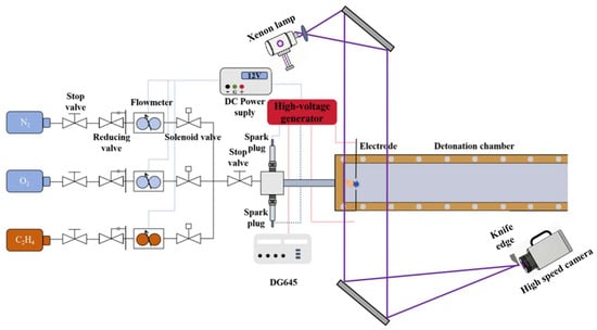
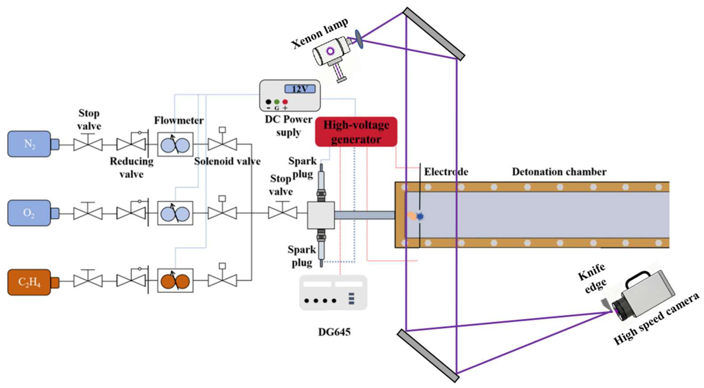
The experimental system primarily consists of a gas supply system, an ignition system, a detonation chamber, an image acquisition system, a timing control system, and a data processing system. As shown in Figure 1, the gas supply system is divided into three lines, namely ethylene (C2H4), oxygen (O2), and nitrogen (N2), each supplied by high-pressure cylinders. Each cylinder is connected to a pressure regulator, a flowmeter, a ball valve, a flame arrester, and a check valve, and the three gas streams are merged into a single line before being delivered to the detonation chamber. During the experiments, the volumetric flow rate of C2H4 was maintained at 0.3 L/min and that of O2 at 0.9 L/min, corresponding to a stoichiometric ratio of ethylene to oxygen. The dilution ratio β is defined herein as the volumetric flow rate ratio of N2 to O2. By varying the N2 flow rate, β can be adjusted to modify the chemical activity of the mixture; a higher dilution ratio indicates weaker chemical activity of the fuel. In this work, β was set at 0.8 in all tested conditions.
Figure 1.
Schematic of the overall experimental setup.
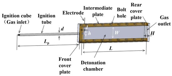
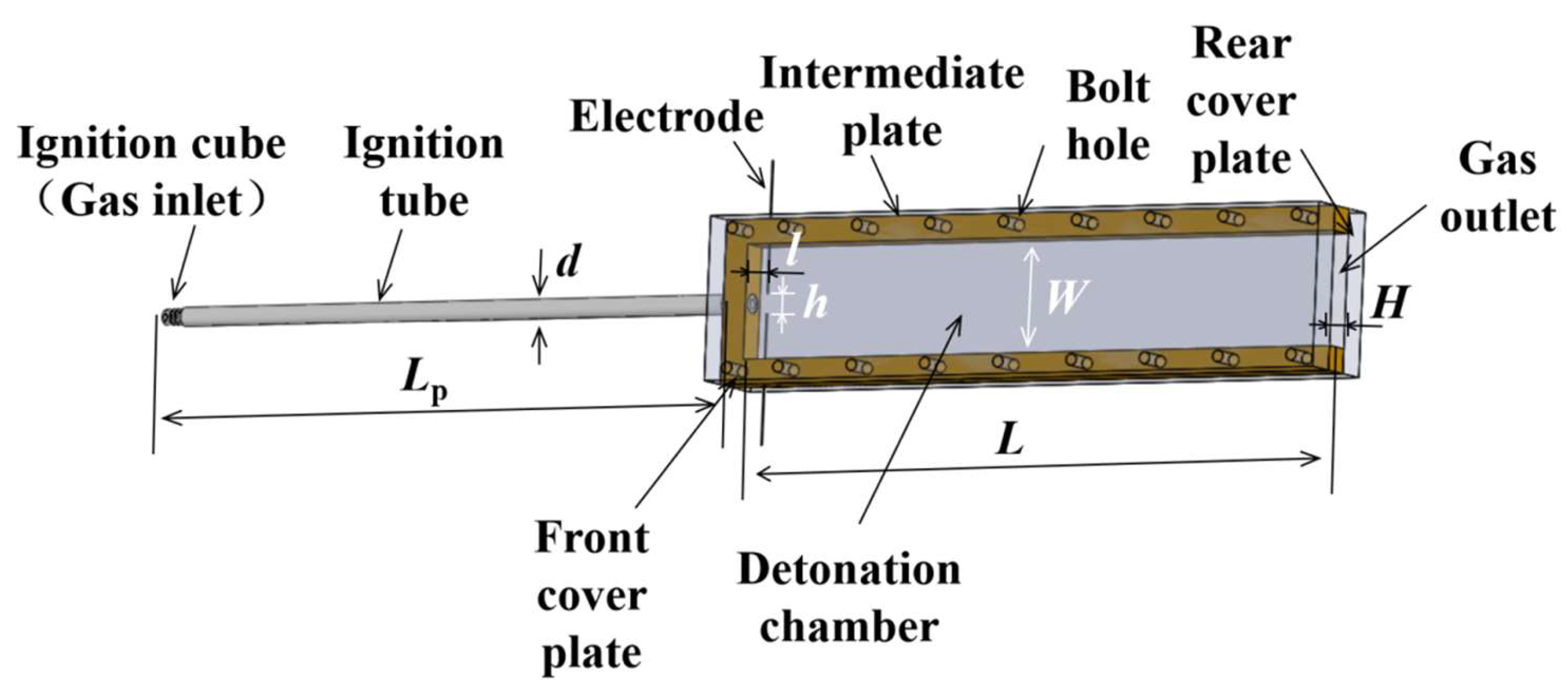
As shown in Figure 2, the detonation chamber is composed of two 20 mm thick acrylic glass plates and one 18 mm thick insulating phenolic board, connected by bolts. The chamber has a width W = 70 mm and a length L = 400 mm. The jet tube has a length Lp = 400 mm and an inner diameter d = 6 mm. The electrodes are tungsten rods with a purity of ≥99.5% and a diameter of 0.5 mm. The distance between the two electrodes is h = 10 mm, and the electrodes are placed at an axial distance l = 10 mm downstream of the jet tube outlet. No electrode deformation was observed after repeated experiments due to the short discharge duration and the high melting point of tungsten. The jet tube dimensions (Lp = 400 mm, d = 6 mm) and chamber geometry were chosen to maintain consistency with our previous studies [7,16] and to provide a well-defined, confined platform for investigating the hot-jet initiation process. In this geometry, the chamber walls generate precursor shock reflections that actively promote re-initiation, as demonstrated in our earlier work [7].
Figure 2.
Configuration of the detonation chamber.
The ignition device used in the experiment consists of a conventional spark plug and an ignition coil. Two ignition methods (with the same total energy) are employed:
Dual-spark-plug ignition (defined as Ignition Approach 1): All the energy from the ignition coil is supplied to the two spark plugs at the head of the jet tube, which discharge simultaneously to ignite the premixed gas inside the jet tube, forming a hot jet that initiates the main detonation chamber. In this case, the electrodes located in the detonation chamber are not discharged.
Single spark plug with electrode discharge ignition (defined as Ignition Approach 2): The energy from the ignition coil is split between one spark plug at the head of the jet tube and the electrodes inside the detonation chamber. The single spark plug first ignites the premixed gas within the jet tube. When the resulting hot jet approaches the electrodes in the detonation chamber, the electrodes are triggered to discharge, initiating the main detonation chamber. The timing sequence between the spark plug and electrode discharge is controlled by a synchronized controller (Stanford DG645, Sunnyvale, CA, USA). Based on 10 repeated measurements, the flame arrival time at the electrode location is 950–970 μs after ignition. The delay between the trigger signal and the actual discharge is approximately 75 μs. Therefore, the electrode discharge is initiated at 875 μs after the flame appears in the tube, ensuring that the discharge coincides with the flame front reaching the electrode location.
The spark plug used in this study is a Guorui Antaixin APS3005S-3D (Shenzhen Atten Technology Co., Ltd., Shenzhen, China), with the following specifications: output voltage 0–30 V, output current 0–5 A, rated voltage 5 V at 3 A, and input voltage 220 V AC ±10%, 50/60 Hz. A single ignition coil is used for each discharge event. The ignition coil circuit consists of three branches: a power supply circuit, a discharge circuit (connected to either the spark plug or the electrodes), and a trigger circuit. The trigger circuit is activated either manually via a battery switch or automatically via a timing controller. The same type of ignition coil is used for both the spark plug and the electrode discharges, and the voltage, current, and pulse duration are approximately identical for both.
Each of the two ignition approaches offers distinct advantages. Ignition Approach 1 concentrates the ignition energy at the head of the jet tube, which leads to a more vigorous flame kernel, faster flame acceleration, and a stronger precursor shock wave ahead of the flame front, resulting in a higher exit velocity as the jet enters the detonation chamber. In contrast, Ignition Approach 2 allocates a portion of the ignition energy to the head of the detonation chamber, where an arc plasma is generated to enhance the diffraction and decay process of the jet. Both approaches will be discussed in detail later in this paper.
It is also worth noting that, owing to the use of a short jet tube and a high dilution ratio (i.e., 0.8), at this dilution level, no detonation wave is formed inside the jet tube under the present conditions. Instead, only a high-speed flame jet enters the detonation chamber. The flame accelerates continuously along the jet tube and reaches its maximum speed at the tube exit.
During the experiments, the following measurement methods were employed. Schlieren imaging was used to capture the discharge process of the electrodes and the diffraction of the flame from the jet tube and its interaction with the electrode arc, respectively. The high-speed camera used was an IX i-SPEED 713 (iX Cameras, Essex, UK). For schlieren imaging of jet diffraction, a Z-type schlieren system was used, consisting of two concave mirrors with a diameter of 300 mm and a focal length of 3 m to reflect a 500 W xenon light source. A Nikon 200 mm f/2 fixed-focus lens was mounted on the high-speed camera. The image resolution was 350 × 350 pixels, providing a field of view of 70 × 70 mm, with a frame rate of 100 kHz. For schlieren imaging of electrode discharge, the image resolution was 340 × 440 pixels, providing a field of view of 70 × 89 mm, with a frame rate of 80 kHz.
3. Results and Discussion
3.1. Electrode Discharge in Detonation Chamber
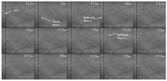
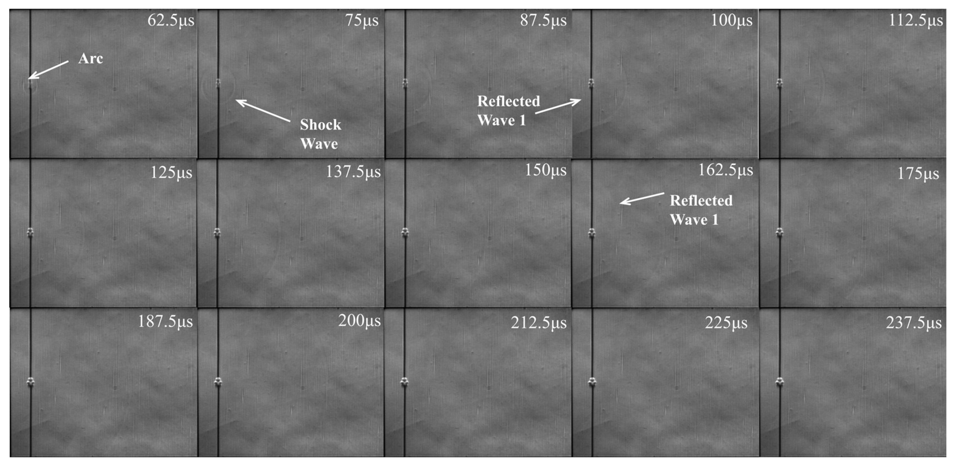
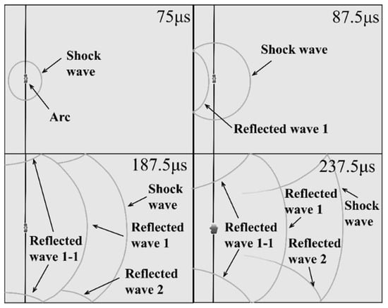
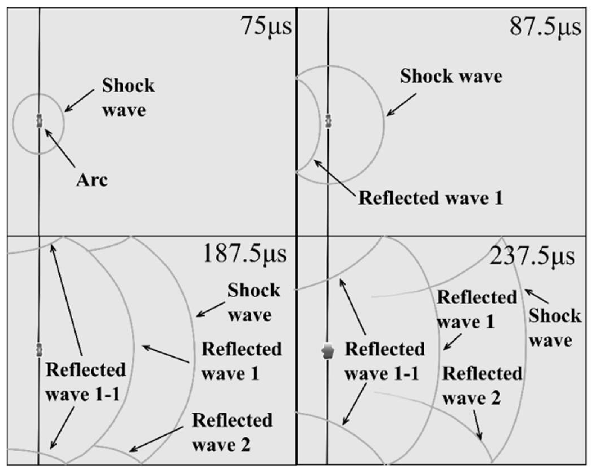
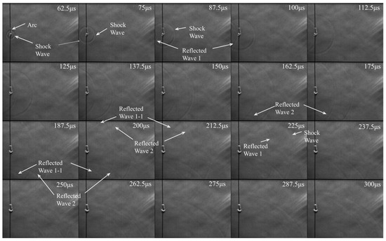
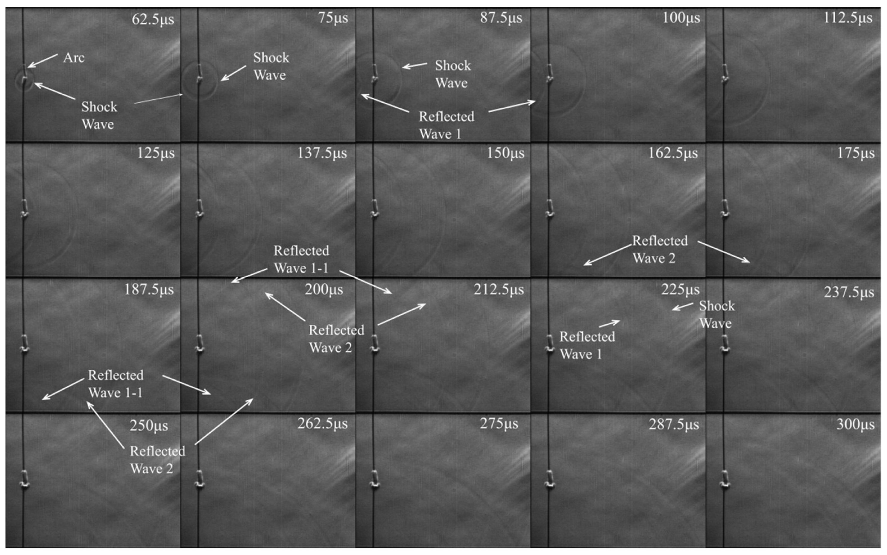
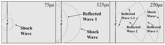
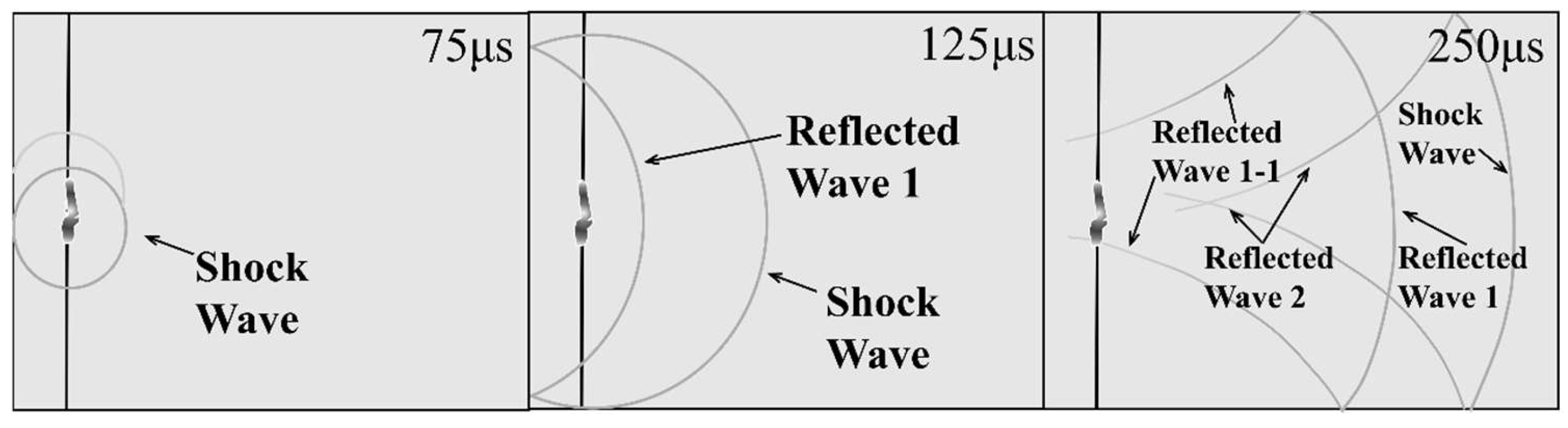
To investigate the electrode discharge process within the detonation chamber and its perturbation of the surrounding flow field, schlieren measurements were conducted. The results are presented in Figure 3, Figure 4, Figure 5 and Figure 6. The raw schlieren images (Figure 3 and Figure 5) have relatively low contrast due to the short exposure time and the nature of the flow features. To facilitate interpretation, raw images were processed using a series of digital image enhancement and feature extraction techniques, including contrast adjustment, noise reduction, and edge detection. The resulting images (Figure 4 and Figure 6) show the extracted shock front with improved clarity.
Figure 3.
Schlieren images of the discharge process with an electrode center spacing of h = 5 mm.
Figure 4.
Extracted flow field structures from Figure 3 for electrode spacing h = 5 mm.
Figure 5.
Schlieren images of the discharge process with an electrode center spacing of h = 10 mm.
Figure 6.
Extracted flow field structures from Figure 5 for electrode spacing h = 10 mm.
As can be seen, at t = 62.5 μs, the electrodes discharge, generating a shock wave with a double-wave symmetric structure. Because the two wavefronts are initially very close to each other, they merge by t = 75 μs into a single elliptical wave that propagates downstream. At t = 87.5 μs, the shock wave traveling toward the inlet of the detonation chamber collides with the chamber wall, producing the first reflected wave (Reflected Wave 1, RW1), which then travels downstream. At t = 137.5 μs, the shock wave impinges on the side wall, generating the second reflected wave (Reflected Wave 2, RW2). At t = 175 μs, RW1, while propagating downstream, first meets the side wall and gives rise to the third reflected wave (Reflected Wave 1-1, RW1-1). Subsequently, at t = 187.5 μs and later (as shown in Figure 4), a complex structure consisting of four coexisting wave systems is formed: the primary shock wave, RW1, RW2, and RW1-1. As this four-wave system continues to travel downstream, it repeatedly interacts with the walls, generating additional reflected waves. Furthermore, a localized high-temperature zone forms between the two electrodes, which has an average area of ~24 mm2.
Figure 5 and Figure 6 present the measurement results for an electrode center spacing of 10 mm. Figure 5 shows the schlieren images, while Figure 6 illustrates the extracted flow field structures based on Figure 5.
Due to the increased electrode spacing, the discharge generates a pair of initially symmetric shock waves. Although the two shock waves are not clearly distinguishable in the raw image at 75 μs due to the weakness of the upper shock, the extracted flow field (Figure 6) reveals the double-shock structure. The presence of two shocks is confirmed by the 62.5 μs image in Figure 5, where both waves are visible. The dynamic propagation process of the shock wave is displayed in Figure 5. At t = 62.5 μs, the electrodes discharge, forming an ionization channel between them and generating primary shock waves that exhibit a pattern of two intersecting circles. Owing to the asymmetric energy distribution between the upper and lower sides, the wavefronts develop in a non-axisymmetric manner.
At t = 87.5 μs, the shock wave traveling toward the detonation chamber inlet first collides with the wall, producing the first reflected wave (RW1), which then propagates downstream. At t = 137.5 μs, the shock wave impinges on the side wall, generating the second reflected wave (RW2). At t = 162.5 μs, RW1, while traveling downstream, meets the side wall for the first time, giving rise to the third reflected wave (RW1-1). By this time, a complex four-wave system becomes clearly visible, consisting of the primary shock wave, RW1, RW2, and RW1-1. As this four-wave system continues to move downstream, it repeatedly interacts with the walls, producing additional reflected waves. For the electrode spacing of 10 mm, a relatively larger high-temperature zone forms between the two electrodes, with an average area of approximately 44 mm2.
These results indicate that under the present energy levels (i.e., 50 mJ), increasing the electrode spacing is advantageous: it not only yields a more complex wave system conducive to hot-spot formation via interaction with the jet but also expands the high-temperature discharge area. Discharge experiments with an electrode spacing of 15 mm were also attempted, and the results are consistent with the above observations, namely a more complex wave system and a larger high-temperature zone. However, at a spacing of 15 mm, the discharge success rate decreases significantly, making it difficult to achieve reliable breakdown. Therefore, an electrode spacing of 10 mm was adopted for all subsequent experiments in this study.
3.2. Detonation Success Rate Under Different Ignition Approaches
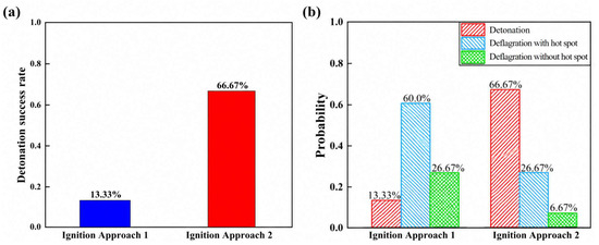
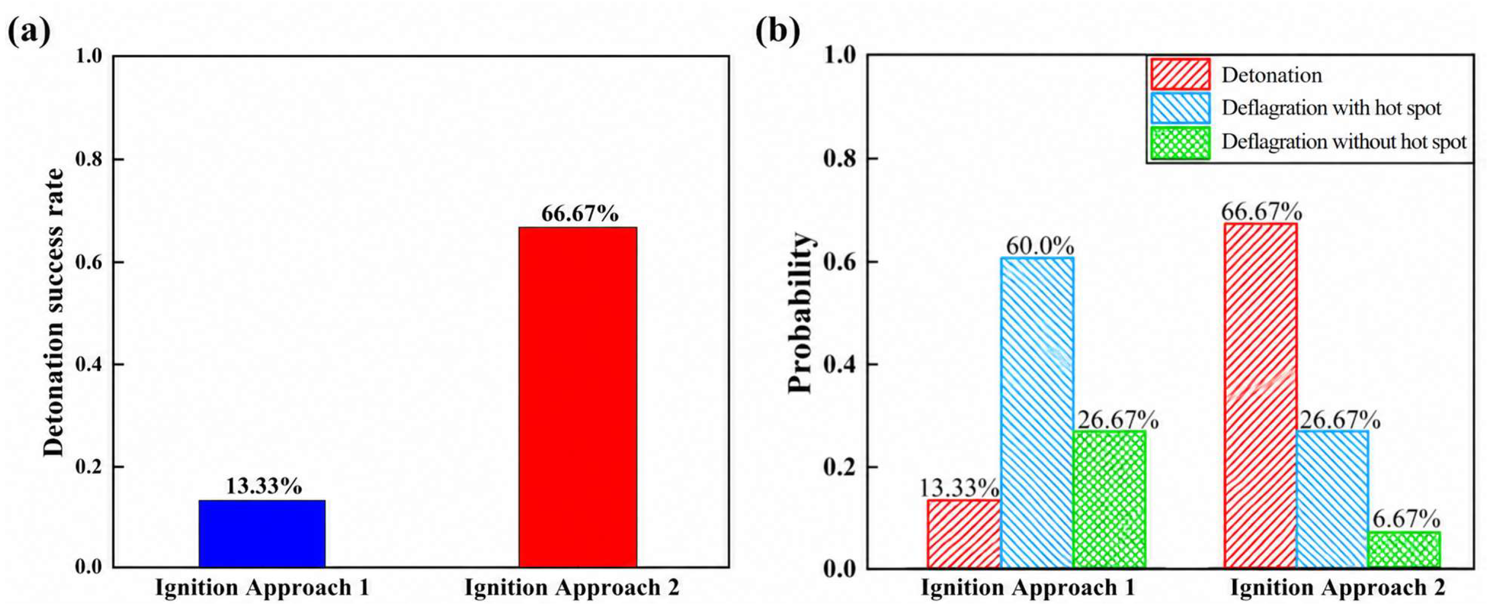
Thirty repeat tests were performed for each ignition method, and the resulting detonation success rates are presented in Figure 7a. Ignition Approach 2 (single spark plug coupled with electrode discharge) yields a success rate of 66.67%, which is substantially higher than the 13.33% obtained with Ignition Approach 1 (dual spark plugs). This finding provides direct evidence that electrode discharge plays a significant role in promoting jet-induced detonation initiation.
Figure 7.
(a) Detonation success rates for the two ignition approaches. (b) Probabilities of successful detonation, deflagration with hot spot, and deflagration without hot spot.
The unsuccessful initiation events can be further classified into two categories: deflagration with hot-spot formation (indicating a near-initiation condition) and deflagration without hot spots. Figure 7b shows the probabilities of each scenario. Under Ignition Approach 1, the deflagration-with-hot-spot mode is the most frequent at 60.0%, followed by ordinary deflagration at 26.67%, while the detonation mode occurs only 13.33%. In contrast, for Ignition Approach 2, the detonation mode dominates at 66.67%, with deflagration with hot spots and ordinary deflagration accounting for 26.67% and 6.67%, respectively.
These comparative results demonstrate that the introduction of electrode discharge significantly improves the initiation probability in the detonation chamber. The interaction between the arc plasma and the exiting jet effectively accelerates the deflagrating flame and promotes the formation of hot spots. More importantly, it substantially enhances the development of these hot spots, making them more capable of triggering local explosions, thereby efficiently converting the deflagration-with-hot-spot mode into a full detonation mode. To assess the statistical significance of the observed difference, a chi-square test was performed on the detonation success rates. The results show a statistically significant difference between the two ignition approaches (p < 0.001), confirming that the enhancement due to electrode discharge is not attributable to random experimental variation.
3.3. Dynamics of Detonation Initiation Process
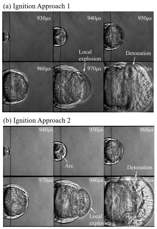
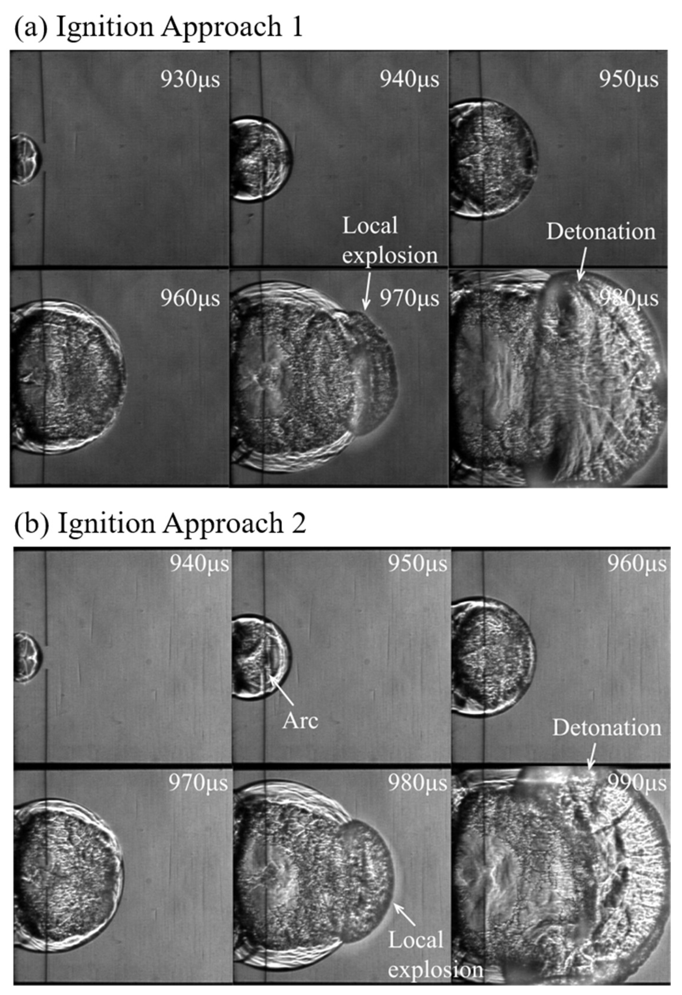
In this section, the dynamic schlieren images are analyzed to compare the initiation processes under the two ignition approaches. Figure 8a shows a successful initiation event (13.33% probability) using Ignition Approach 1, and Figure 8b shows a successful initiation event (66.67% probability) using Ignition Approach 2. The overall initiation process is similar for both approaches. After the jet exits the tube, the flame front decelerates due to diffraction, and in the first frame, the flame has already decoupled from the shock wave. In the second frame, the flame front accelerates rapidly. In the third frame, the leading edge of the flame in both cases catches up with the shock wave front, indicating a tendency toward recoupling. In the fourth frame, the main flame continues to propagate downstream; a strongly coupled region (hot spot) is visible at the leading edge, while along the flame sides a distinct decoupling zone between the flame and the shock wave has formed. In the fifth frame, the strongly coupled region undergoes local chemical acceleration, instantly forming a high-temperature, high-pressure detonation bubble—a spherical detonation wave that expands rapidly outward from the local explosion site. This new detonation wave then couples strongly with the flame, forming a rapidly expanding detonation combustion zone. Meanwhile, the decoupling between the lateral flame edges and the shock wave becomes even more pronounced, revealing a complex multi-wave structure resulting from the superposition of multiple internal combustion waves. In the sixth frame, the newly formed detonation wave expands rapidly in all directions, covering the entire flame front. Subsequently, a stable detonation propagation phase is established, with the highly coupled structure moving downstream toward the end of the detonation chamber.
Figure 8.
Schlieren images showing the dynamics of detonation initiation processes: (a) Ignition Approach 1; (b) Ignition Approach 2.
A key difference is observed in Figure 8b (Approach 2): at t = 950 μs, a prominent local “black spot” (labeled “Arc”) appears in the electrode region due to the discharge. This indicates that in Approach 1, the formation of a hot spot and the resulting local explosion are driven primarily by the unsteady effect of corner expansion waves [5]. The sudden area expansion from the jet tube to the detonation chamber generates corner expansion waves on both sides of the emerging flame (see Figure 8a at 960 μs and Figure 8b at 970 μs). The coupling between the unsteady decay of shock waves induced by these corner expansion waves and the chemical kinetics of the reaction zone leads to re-initiation. In Approach 2, however, the hot spot and local explosion are driven simultaneously by both the unsteady corner-expansion-wave effect and the electrode discharge. This is the fundamental reason for the significantly higher detonation success rate of Approach 2, despite the overall similarity of the initiation sequences.
However, the deeper reasons why electrode discharge promotes hot-spot formation and development are not easily discernible from Figure 8, because the framing rate is still relatively low, and the events occurring between 940 μs and 950 μs in Figure 8b (the discharge process) were not captured. We hypothesize two possible mechanisms: (1) the instantaneous high temperature and highly active free radicals generated by the discharge, and (2) the shock wave generated by the discharge enhancing the unsteady corner-expansion-wave effect. From Figure 8b and other discharge cases, it is clear that the discharge occurs after the emerging flame has already covered the electrode location (e.g., at t = 950 μs in Figure 8b). Creating a high-temperature region and active free radicals through discharge in already-burned hot products is unlikely to significantly affect flame acceleration. Therefore, we favor the second mechanism: the discharge-induced shock wave interacts with the corner expansion waves originating from the sudden area expansion at the jet tube exit. Consequently, the unsteady decay of the leading shock is mitigated, and the local pressure and temperature are enhanced, leading to a much higher probability of hot-spot formation and subsequent detonation. Nevertheless, we motivate future numerical simulations and higher-frame-rate optical measurements to confirm this underlying mechanism.
For the two types of failed initiation (i.e., those with a hot spot and those without), the dynamic evolution of the flame remains largely similar between the two ignition methods, differing primarily in their occurrence probabilities, as shown in Figure 7. In failures accompanied by a hot spot, a hot spot forms at the flame tip but does not trigger a local explosion. In the other type, no hot spot develops.
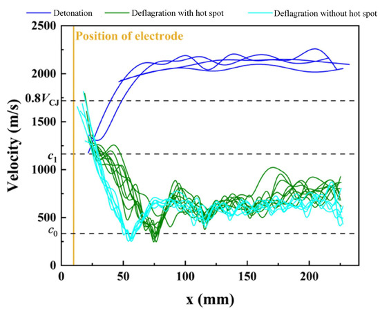
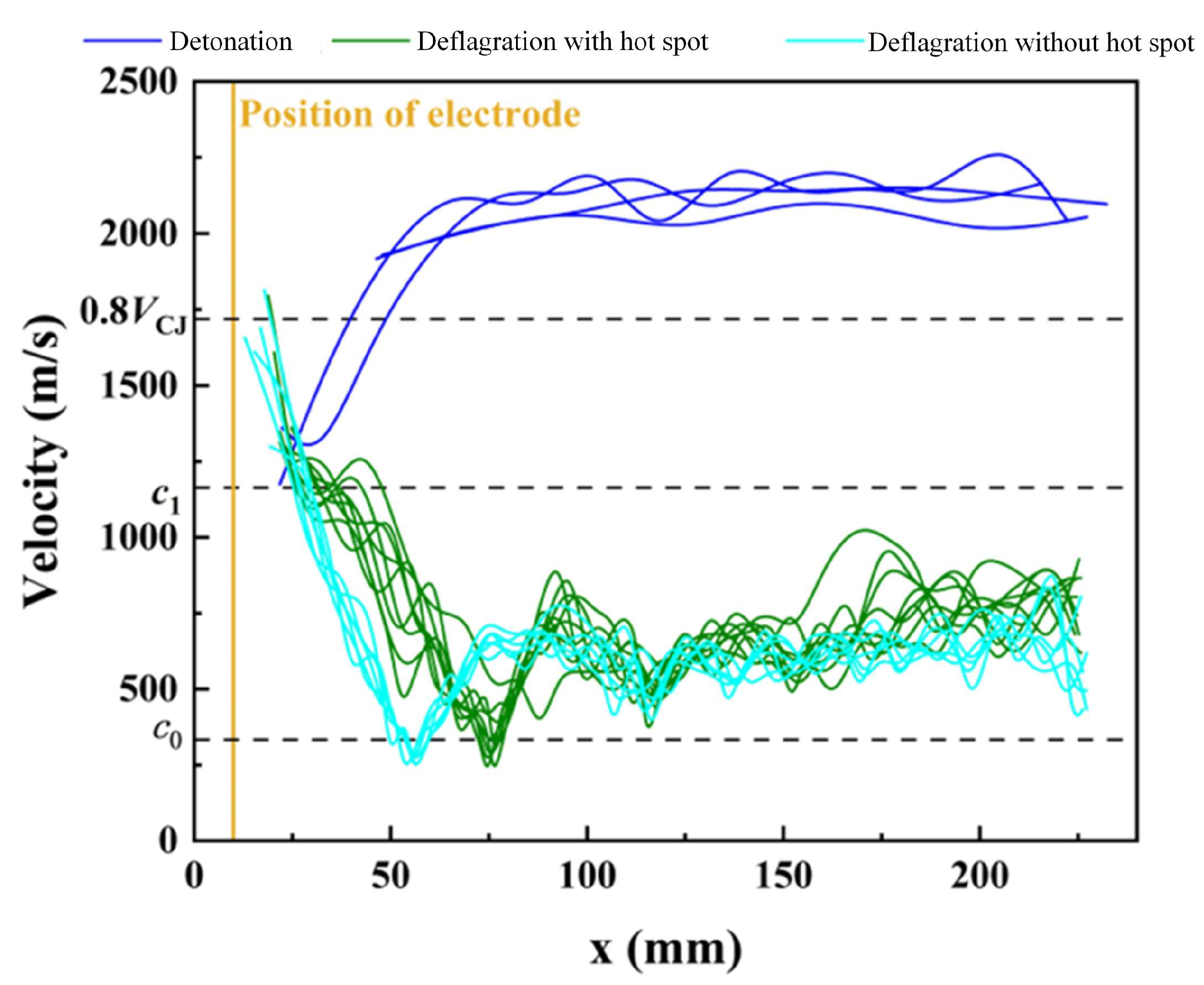
To further characterize the different initiation modes, we extracted the flame propagation velocity within the detonation chamber from all 30 repeated experiments for each ignition approach. The velocity was determined from the flame tip position between successive schlieren frames. The flame tip position was identified as the leading edge of the shock front, detected by the maximum intensity gradient along the axial direction. The velocity was calculated from the flame tip displacement between successive frames acquired at 100 kHz (10 μs time interval). To reduce the effect of pixel-level noise, a B-spline curve was fitted to the discrete velocity data points, yielding the smooth velocity evolution curves presented in Figure 9 and Figure 10. As shown in Figure 7, for Ignition Approach 1, among the 30 experiments, there were 4 successful initiations (13.33%), 18 failures of the deflagration-with-hot-spot mode (60%), and 8 failures of the deflagration-without-hot-spot mode (26.67%). For clarity, Figure 9 presents the velocity evolution curves for the 4 successful initiations (blue curves), 9 representative cases of the deflagration-with-hot-spot mode (green curves), and 6 representative cases of the deflagration-without-hot-spot mode (cyan curves) under this ignition approach.
Figure 9.
Velocity evolution curves under Ignition Approach 1 for four successful initiations (blue curves), nine representative cases of deflagration with hot spot (green curves), and six representative cases of deflagration without hot spot (cyan curves).
Figure 10.
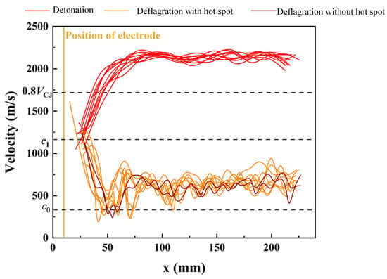
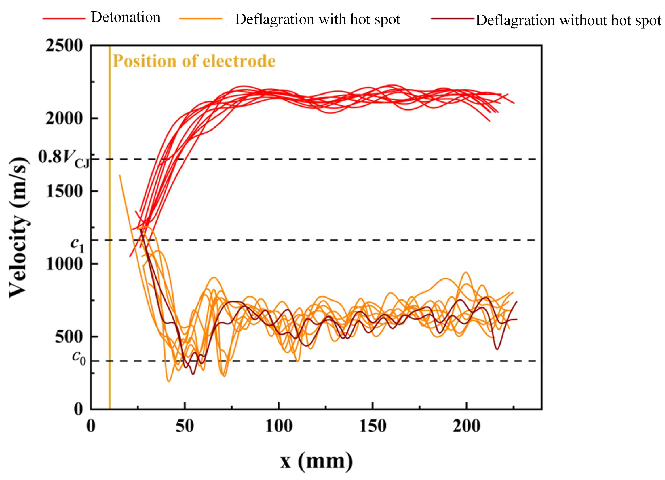
Velocity evolution curves under Ignition Approach 2 for ten representative successful initiations (red curves), eight deflagration-with-hot-spot cases (orange curves), and two deflagration-without-hot-spot cases (brown curves).
It can be seen from the figure that, in the four successful initiation cases, the flame velocity exceeds 0.8VCJ = 1718.88 m/s at approximately 50 mm from the detonation chamber inlet due to a local explosion. The velocity continues to increase thereafter, and eventually the flame front propagates stably downstream in the range of 1900–2250 m/s. In the deflagration-with-hot-spot mode, a velocity peak forms at about 40 mm from the inlet, indicating an acceleration attempt promoted by the hot spot. However, since no local explosion is triggered, the velocity fails to reach 0.8VCJ and subsequently decreases continuously, eventually stabilizing between c0 and c1. In the deflagration-without-hot-spot mode, no such acceleration attempt is observed; the flame velocity decreases steadily after exit and also stabilizes between c0 and c1.
Similarly, for Ignition Approach 2, among the 30 repeated experiments, 20 resulted in successful initiation (66.67%), 8 fell into the deflagration-with-hot-spot failure mode (26.67%), and the remaining 2 exhibited deflagration without a hot spot (6.67%). Figure 10 presents the velocity evolution curves for 10 representative successful initiation cases (red curves), 8 deflagration-with-hot-spot cases (orange curves), and the 2 deflagration-without-hot-spot cases (brown curves) under this ignition approach.
As can be seen in Figure 10, for successful initiation cases, the flame velocity exceeds the threshold of 0.8VCJ = 1718.88 m/s at approximately 50 mm from the detonation chamber inlet, driven by a local explosion. The velocity continues to rise thereafter, and the flame front eventually propagates stably downstream in the range of 2100–2200 m/s. In the deflagration-with-hot-spot mode, a distinct velocity peak appears around 30 mm from the inlet, reflecting an acceleration attempt promoted by the hot spot. However, because no local explosion is triggered, the peak remains below 0.8VCJ, after which the velocity declines steadily and finally stabilizes between c0 and c1. In the deflagration-without-hot-spot mode, no such acceleration effort is evident; the flame velocity decreases monotonically following exit and likewise settles between c0 and c1.
A comparison between the two ignition approaches reveals that, under Approach 1, the jet exit velocity is generally higher due to the full concentration of ignition energy at the jet tube head. In contrast, Approach 2 allocates part of the energy to the electrode discharge at the detonation chamber inlet, which, despite yielding a slightly lower initial jet exit velocity, dramatically enhances the overall initiation probability as well as the likelihood of hot-spot formation and subsequent local explosion.
4. Summary and Conclusions
In this work, we have experimentally investigated the use of ordinary electrode breakdown discharge as a low-complexity, plasma-assisted method to enhance jet-induced detonation initiation. The main findings and conclusions are summarized as follows:
Under identical total ignition energy, coupling a single spark plug with electrode discharge (Ignition Approach 2) increases the detonation success rate from 13.33% (dual-spark-plug approach) to 66.67% over 30 repeated runs. This demonstrates that a simple arc plasma, without the need for expensive nanosecond-pulse power supplies, significantly promotes jet-induced initiation.
Successful initiation follows a similar dynamic sequence in both ignition methods: flame deceleration due to area expansion, recoupling with the shock wave, formation of a strongly coupled hot spot, local explosion, and finally stable detonation propagation. However, the electrode-discharge approach yields a much higher probability of transitioning from the deflagration-with-hot-spot mode to full detonation. The velocity curves show that in Approach 2 the acceleration attempt occurs earlier (≈30 mm from the inlet for hot-spot failures, compared with ≈40 mm in Approach 1), and successful initiations reach stable detonation velocities of 2100–2200 m/s. The quantitative velocity and success-rate data that distinguish between three combustion modes offer a benchmark for future numerical and experimental studies.
High-speed schlieren images reveal that the electrode discharge takes place after the emerging flame has already covered the electrodes. Therefore, the promoting effect is unlikely to come from high temperature or free radicals deposited in already-burned products. Instead, the shock wave emitted by the discharge is hypothesized to enhance the unsteady corner-expansion-wave effect that governs re-initiation. This shock-wave reinforcement explains why Approach 2 dramatically increases hot-spot formation and the likelihood of local explosion.
The proposed electrode-discharge scheme offers a compact solution in the sense that it achieves a high detonation success rate without requiring an increase in the jet tube length.
The current framing rate (80–125 kHz) is insufficient to resolve the detailed interaction between the discharge shock and the flame on sub-microsecond scales. We therefore motivate future numerical simulations and higher-frame-rate optical measurements (e.g., >500 kHz) to directly confirm the proposed shock-wave enhancement mechanism.
In conclusion, ordinary electrode breakdown discharge provides a simple yet effective means to boost jet-induced detonation initiation by amplifying the unsteady expansion-wave-driven re-initiation process. This finding opens a practical path toward reliable, low-cost ignition systems for pulse and rotating detonation engines.
Author Contributions
Z.L.: Investigation (lead); Methodology (lead); Visualization (lead); Writing—original draft (equal). B.Z.: Formal anal-ysis (equal); Visualization (equal); Writing—original draft (equal). Q.L.: Conceptualization (lead); Investigation (equal); Data curation (equal); Writing review & editing (lead). W.F.: Fund-ing acquisition (lead); Supervision (lead). All authors have read and agreed to the published version of the manuscript.
Funding
This work was funded by the National Natural Science Foundation of China under grant number 52336006.
Data Availability Statement
The data presented in this study are available on request from the corresponding author.
Conflicts of Interest
The authors declare no conflict of interest.
References
- Roy, G.D.; Frolov, S.M.; Borisov, A.A.; Netzer, D.W. Pulse Detonation Propulsion: Challenges, Current Status, and Future Perspective. Prog. Energy Combust. Sci. 2004, 30, 545–672. [Google Scholar] [CrossRef] [Scilit]
- Wolanski, P. Detonative Propulsion. Proc. Combust. Inst. 2013, 34, 125–158. [Google Scholar] [CrossRef] [Scilit]
- Lee, J.H.S. The Detonation Phenomenon; Cambridge University Press: Cambridge, UK, 2008. [Google Scholar]
- Wu, Y.H.; Yang, V.; Chang, S.C. Effects of Ignition Energy on Detonation Initiation. In AIAA Aerospace Sciences Meeting, Reno, NV, USA, 10–13 January 2000; American Institute of Aeronautics and Astronautics: Reston, VA, USA, 2000. [Google Scholar]
- Pintgen, F.; Shepherd, J.E. Detonation Diffraction in Gases. Combust. Flame 2009, 156, 665–677. [Google Scholar] [CrossRef] [Scilit]
- Knystautas, R.; Lee, J.H.; Guirao, C.M. The Critical Tube Diameter for Detonation Failure in Hydrocarbon-Air Mixtures. Combust. Flame 1982, 48, 63–83. [Google Scholar] [CrossRef] [Scilit]
- Zheng, J.W.; Lei, Q.C.; Zhao, X.C.; Fan, W. Experimental Characterization of Detonation Initiation Modes in a Confined Chamber Flush-Mounted with Small-Diameter Ignition Tubes. Proc. Combust. Inst. 2021, 38, 3741–3748. [Google Scholar] [CrossRef] [Scilit]
- Moen, I.O.; Sulmistras, A.; Thomas, G.O.; Bjerketvedt, D.; Thibault, P.A. Influence of Cellular Regularity on the Behavior of Gaseous Detonations. Prog. Astronaut. Aeronaut. 1986, 106, 220–243. [Google Scholar] [CrossRef] [Scilit]
- Shepherd, J.E. Detonation in Gases. Proc. Combust. Inst. 2009, 32, 83–98. [Google Scholar] [CrossRef] [Scilit]
- Murray, S.B.; Lee, J.H. On the Transformation of Planar Detonation to Cylindrical Detonation. Combust. Flame 1983, 52, 269–289. [Google Scholar] [CrossRef] [Scilit]
- Edwards, D.H.; Thomas, G.O.; Nettleton, M.A. The Diffraction of a Planar Detonation Wave at an Abrupt Area Change. J. Fluid Mech. 1979, 95, 79–96. [Google Scholar] [CrossRef] [Scilit]
- Desbordes, D. Transmission of Overdriven Plane Detonations: Critical Diameter as a Function of Cell Regularity and Size. Prog. Astronaut. Aeronaut. 1988, 114, 170–185. [Google Scholar] [CrossRef] [Scilit]
- Kuznetsov, M.S.; Alekseev, V.I.; Dorofeev, S.B. Comparison of Critical Conditions for DDT in Regular and Irregular Cellular Detonation Systems. Shock Waves 2000, 10, 217–223. [Google Scholar] [CrossRef] [Scilit]
- Eckett, C.A.; Quirk, J.J.; Shepherd, J.E. The Role of Unsteadiness in Direct Initiation of Gaseous Detonations. J. Fluid Mech. 2000, 421, 147–183. [Google Scholar] [CrossRef] [Scilit]
- Arienti, M.; Shepherd, J.E. A Numerical Study of Detonation Diffraction. J. Fluid Mech. 2005, 529, 117–146. [Google Scholar] [CrossRef] [Scilit]
- Li, X.; Lei, Q.C.; Zhao, X.C.; Zheng, J.W.; Zhang, Q.B.; Fan, W. Phenomenon and Analysis of Direct Initiation of Detonation Using Multiple Turbulent Flame Jets. Phys. Fluids 2022, 34, 115104. [Google Scholar] [CrossRef] [Scilit]
- Zhao, W.; Liang, J.; Deiterding, R.; Cai, X.; Wang, X. Effect of Transverse Jet Position on Flame Propagation Regime. Phys. Fluids 2021, 33, 091704. [Google Scholar] [CrossRef] [Scilit]
- Yang, P.; Li, H.; Chen, Z.; Wang, C.; Teng, H. Numerical Investigation on Movement of Triple Points on Oblique Detonation Surfaces. Phys. Fluids 2022, 34, 066113. [Google Scholar] [CrossRef] [Scilit]
- Peswani, M.; Maxwell, B.M. Detonation Wave Diffraction in Stoichiometric C2H4/O2 Mixtures Using a Global Four-Step Combustion Model. Phys. Fluids 2022, 34, 106104. [Google Scholar] [CrossRef] [Scilit]
- Teng, H.; Ng, H.D.; Yang, P.; Wang, K. Near-Field Relaxation Subsequent to the Onset of Oblique Detonations with a Two-Step Kinetic Model. Phys. Fluids 2021, 33, 096106. [Google Scholar] [CrossRef] [Scilit]
- Starikovskiy, A.; Aleksandrov, N. Plasma-Assisted Ignition and Combustion. Prog. Energy Combust. Sci. 2013, 39, 61–110. [Google Scholar] [CrossRef] [Scilit]
- Ju, Y.; Sun, W. Plasma Assisted Combustion: Dynamics and Chemistry. Prog. Energy Combust. Sci. 2015, 48, 21–83. [Google Scholar] [CrossRef] [Scilit]
- Starikovskaia, S.M. Plasma Assisted Ignition and Combustion. J. Phys. D Appl. Phys. 2006, 39, R265–R299. [Google Scholar] [CrossRef] [Scilit]
- Gray, J.A.T.; Lacoste, D.A. Effect of the Plasma Location on the Deflagration-to-Detonation Transition of a Hydrogen-Air Flame Enhanced by Nanosecond Repetitively Pulsed Discharges. Proc. Combust. Inst. 2021, 38, 3463–3472. [Google Scholar] [CrossRef] [Scilit]
- Vorenkamp, M.; Steinmetz, S.A.; Chen, T.Y.; Mao, X.; Starikovskiy, A.; Kliewer, C.; Ju, Y. Plasma-Assisted Deflagration to Detonation Transition in a Microchannel with Fast-Frame Imaging and Hybrid fs/ps Coherent Anti-Stokes Raman Scattering Measurements. Proc. Combust. Inst. 2023, 39, 5561–5569. [Google Scholar] [CrossRef] [Scilit]
- Cherif, M.A.; Shcherbanev, S.A.; Starikovskaia, S.M.; Vidal, P. Effect of Non-Equilibrium Plasma on Decreasing the Detonation Cell Size. Combust. Flame 2020, 217, 1–3. [Google Scholar] [CrossRef] [Scilit]
- Huang, Z.; Zhang, H. Ignition and Deflagration-to-Detonation Transition in Ethylene/Air Mixtures Behind a Reflected Shock. Phys. Fluids 2022, 34, 086105. [Google Scholar] [CrossRef] [Scilit]
- Sun, J.; Yu, D.; Yang, P.; Wang, Y.; Wang, S.; Chen, Z. Detonation Initiation Induced by Dual Hot Spots: A Computational Study. J. Fluid Mech. 2025, 1010, A60. [Google Scholar] [CrossRef] [Scilit]
- Frolov, S.M.; Basevich, V.Y.; Aksenov, V.S.; Polikhov, S.A. Detonation initiation in liquid fuel sprays by successive electric discharges. Dokl. Phys. Chem. 2004, 394, 39–41. [Google Scholar] [CrossRef] [Scilit]
Disclaimer/Publisher’s Note: The statements, opinions and data contained in all publications are solely those of the individual author(s) and contributor(s) and not of MDPI and/or the editor(s). MDPI and/or the editor(s) disclaim responsibility for any injury to people or property resulting from any ideas, methods, instructions or products referred to in the content. |
© 2026 by the authors. Licensee MDPI, Basel, Switzerland. This article is an open access article distributed under the terms and conditions of the Creative Commons Attribution (CC BY) license.