


Abstract
This paper presents a comparative analysis of three magnetic-integrated LCL-derived filter configurations for suppressing high-frequency switching harmonics in avionics power-conversion systems: the integrated LLCL filter, the magnetic-integrated multi-trap LCL filter, and the magnetic-integrated trapped-LCL filter. The high-frequency harmonics considered in this study originate primarily from the pulse-width-modulated (PWM) switching process and can increase current distortion, electrical and magnetic losses, component stress, and the potential for electromagnetic interference in aircraft electrical systems. To enable a consistent comparison, the three filter configurations are evaluated within a unified analytical framework under common system-level operating conditions, while retaining their topology-specific passive and magnetic parameters according to their respective design requirements. The framework distinguishes aggregate total harmonic distortion (THD) from attenuation at targeted switching-frequency bands and incorporates the effects of resonant branches and magnetic coupling. The simulated current THD values of the LLCL, multi-trap LCL, and trapped-LCL filters are 0.82%, 0.84%, and 1.13%, respectively, while their estimated total filter losses are 24.98 W, 59.74 W, and 40.49 W. At the 1 kW operating point, these losses correspond to 2.50%, 5.97%, and 4.05% of rated power, respectively. The results show that the LLCL filter achieves the lowest aggregate THD and estimated loss under the investigated conditions, whereas the multi-trap and trapped-LCL configurations provide additional capability for targeted attenuation of selected switching-frequency components through their resonant structures. Hardware-in-the-loop (HIL) results further support the electrical filtering and dynamic behavior of the investigated concepts. The comparison demonstrates that minimum THD, minimum loss, targeted switching-harmonic attenuation, and magnetic integration are distinct design objectives; therefore, topology selection should be based on the specific requirements and constraints of the intended avionics application.
1. Introduction
High-frequency power-electronic converters are widely employed in modern avionics power systems due to their high efficiency, reduced size, and enhanced controllability [1,2,3,4,5]. The continued electrification of aircraft has further increased the penetration of power-electronic conversion across AC, variable-frequency AC, and DC electrical architectures [6]. Aircraft electrical architectures may incorporate fixed-frequency, variable-frequency, and DC distribution systems, while increasing electrification has intensified the use of power-electronic conversion stages [7]. Despite these advantages, PWM operation introduces high-frequency voltage and current components that must be considered when designing the converter and its associated passive filtering stage.
The principal source of the high-frequency harmonics considered in this study is the periodic switching action of the semiconductor devices. The PWM switching waveform produces spectral components concentrated around the switching frequency and its multiples, with the exact harmonic distribution depending on the converter topology and modulation strategy. For the single-phase H-bridge configuration considered in the detailed filter analysis, the selected modulation produces a dominant switching-harmonic band around , while additional higher-frequency components may occur around subsequent switching-frequency multiples. Nonidealities such as dead time, DC-link variations, device switching characteristics, and operating-point changes can introduce further spectral components [7].
These high-frequency harmonics can increase RMS current, winding and magnetic-core losses, electrical stress on passive components, and the possibility of resonant interaction between the converter filter and the surrounding AC-side impedance. They are also relevant to conducted electromagnetic disturbance in the electrically sensitive environment of aircraft systems. Consequently, high-frequency harmonic suppression must be considered together with stringent aircraft constraints on mass, volume, efficiency, reliability, and electromagnetic compatibility [8,9,10].
Figure 1 illustrates a representative 12-pulse transformer–rectifier architecture used to provide DC power from an aircraft AC supply. The arrangement consists of phase-shifted transformer secondary windings feeding two rectifier bridges whose DC outputs are combined to supply a DC load. The two transformer output windings are connected in Y and Δ to introduce the approximately 30° phase displacement required between the two six-pulse rectifier input-voltage sets. Consequently, the characteristic harmonics produced by the two six-pulse bridges are phase shifted relative to each other, allowing cancelation or substantial reduction in selected low-order input-current harmonics when the two bridge contributions are combined. This phase-shifting principle is the basis of the 12-pulse transformer–rectifier arrangement shown in Figure 1. The figure is included only to establish the aircraft power-conversion context and to illustrate the location at which passive input filtering may be employed. The passive filter shown in Figure 1 is therefore schematic and is not one of the three magnetic-integrated filters quantitatively evaluated in this study. Consequently, its input-current spectrum is not used as a performance result in the subsequent comparison; the harmonic and FFT-based evaluations reported in Section 5 and Section 6 correspond to the explicitly parameterized single-phase PWM AC/DC converter and the investigated LLCL, multi-trap LCL, and trapped-LCL filters.
Figure 1.
Representative 12-pulse transformer–rectifier architecture illustrating a possible passive input-filter location in an aircraft electrical system; the filter is shown schematically for system-level context and is not quantitatively evaluated in this study.
Conventional passive L and LC filters can be employed to attenuate converter-generated switching harmonics. However, obtaining sufficient high-frequency attenuation with these first- and second-order structures may require relatively large inductance values, which can increase magnetic mass and volume. The third-order LCL filter provides a steeper high-frequency attenuation characteristic while requiring less total inductance than a simple L filter [8,9,10,11]. Its principal disadvantage is the resonance introduced by the interaction among the two inductors and the filter capacitor, which must be properly considered in both filter and controller design [10,11,12].
Several LCL-derived resonant-filter configurations have therefore been investigated to improve attenuation around selected switching-frequency regions. The LLCL filter introduces an additional resonant branch that creates a transmission zero near a selected switching harmonic, allowing increased attenuation without requiring a substantial increase in the main filter inductance [13,14,15,16,17]. The design of the LLCL resonant branch requires coordinated selection of its resonant inductance and capacitance, and its behavior can be modified when the inductive elements are magnetically coupled [18]. Multi-trap LCL structures extend this principle by introducing additional resonant paths so that more than one switching-frequency component can be selectively attenuated [19,20,21,22].
Magnetic integration provides a complementary approach by implementing multiple inductive functions through coupled windings on a common magnetic structure. This approach can reduce the number of discrete magnetic components and improve functional integration [23,24,25]. However, mutual inductance is linked to the corresponding self-inductances, winding arrangement, magnetic reluctance paths, and air gaps; therefore, it cannot always be treated as an independently selectable circuit parameter. Magnetic integration also introduces additional considerations related to coupling polarity, parameter sensitivity, winding loss, magnetic-core loss, and the interaction between coupled resonant modes.
Although these filter families have individually demonstrated effective switching-harmonic attenuation, direct comparison remains difficult because their operating conditions, resonant targets, magnetic structures, and evaluation metrics are not generally identical. Moreover, aggregate THD is frequently used as the principal performance index even though a resonant trap is designed to suppress particular switching-frequency components. A filter can therefore exhibit a deeper attenuation notch at a targeted switching frequency without necessarily producing the lowest aggregate THD.
Previous studies, including the authors’ earlier work, have investigated individual magnetic-integrated and multi-trap filter configurations [23,24,25]. Trapped-LCL structures have also been reported previously as resonant extensions of conventional LCL filters [20]. However, those studies did not establish the common analytical and performance-evaluation framework adopted here for comparing the three configurations under a consistent set of criteria. Accordingly, the present work does not claim novelty for the individual LLCL, multi-trap LCL, or trapped-LCL topologies. Instead, its contribution lies in placing representative magnetic-integrated implementations of these filter families within a common analytical and engineering framework and distinguishing their topology-specific advantages and limitations under a consistent set of system-level operating conditions.
The main contributions of this paper are summarized as follows:
- A unified analytical framework is established for comparing the integrated LLCL, magnetic-integrated multi-trap LCL, and magnetic-integrated trapped-LCL configurations under common system-level operating conditions. The framework incorporates topology-dependent resonant impedances and magnetic-coupling relationships rather than relying only on a generic LCL transfer function.
- A comparative assessment is performed in terms of harmonic performance, THD, filter loss, and magnetic integration. In particular, aggregate THD is separated from attenuation at targeted switching-frequency bands, allowing the resonant behavior of the three configurations to be compared without assuming that the lowest THD necessarily corresponds to the deepest switching-frequency attenuation.
- Engineering design guidance is derived for the selection of magnetic-integrated LCL-derived filters for avionics applications. The comparison considers the trade-offs among targeted harmonic attenuation, electrical loss, resonant complexity, functional magnetic integration, dynamic behavior, and the scope of the available HIL validation.
The remainder of this paper is organized as follows. Section 2 reviews the fundamental characteristics of LCL-based filters and establishes the basic terminology and circuit relationships used throughout the paper. Section 3 describes the three investigated magnetic-integrated filter configurations. Section 4 establishes the unified modeling and design framework, including equivalent circuit modeling, resonance and harmonic attenuation, magnetic coupling, design constraints, performance metrics, stability considerations, and dynamic modeling. Section 5 presents the comparative performance analysis based on the common simulation platform. Section 6 presents the HIL experimental platform and discusses steady-state, dynamic, and simulation–experimental results. Section 7 discusses the design constraints, suitability, trade-offs, and engineering implications of the investigated filters for avionics applications. Finally, Section 8 summarizes the main conclusions and limitations of the study.
2. Background of LCL-Based Filters
LCL filters are widely employed in power-electronic converter interfaces because they provide a higher high-frequency attenuation rate than conventional L and LC filters while requiring comparatively smaller inductance values [8,9,10,11]. The basic LCL structure consists of a converter-side inductance , a shunt filter capacitor , and an AC-side inductance , as illustrated in Figure 2.
Figure 2.
Basic LCL filter topology showing the converter-side inductance , filter capacitor , and AC-side inductance .
Throughout this paper, the subscripts and denote the converter-side and AC-side quantities, respectively. Accordingly, and represent the converter-side inductance and current, whereas and represent the AC-side inductance and current. This notation is adopted consistently for all subsequent circuit models.
The basic configuration considered in the following derivation is shown in Figure 2.
Let denote the PWM converter voltage, the filter-capacitor voltage, and the AC-side voltage. Applying Kirchhoff’s voltage law to the converter-side and AC-side inductors and Kirchhoff’s current law at the capacitor node gives
and
Equations (1a)–(1c) describe the basic third-order dynamics of the LCL network. Eliminating and yields the differential equation relating the converter voltage, AC-side voltage, and AC-side current:
For the converter-voltage-to-AC-side-current transfer function, is treated as an independent disturbance and set to zero. Assuming zero initial conditions and applying the Laplace transform to Equation (1d) gives
Equation (1) follows directly from the circuit equations of Figure 2 and provides the baseline transfer function used later to construct the unified analytical framework for the three LCL-derived filter configurations.
The third-order denominator of Equation (1) provides a high-frequency attenuation slope approaching B/decade in the ideal asymptotic region, which is substantially steeper than that of first-order inductive filtering. However, the interaction among , , and introduces an inherent resonance. For the ideal uncoupled LCL configuration, the resonance frequency is determined by the converter-side inductance , AC-side inductance , and shunt capacitance [11]:
Equation (2) represents the uncoupled LCL resonance and is used as an initial design relation. When magnetic coupling or additional resonant branches are introduced, the effective inductances and the resulting poles of the filter change; therefore, the final resonance frequencies must be determined from the corresponding coupled topology rather than from Equation (2) alone.
The LCL resonance must be properly considered because insufficient damping can produce amplification around the resonant frequency and can adversely affect the converter control system. Passive damping can be introduced by adding resistive elements to the filter, although this increases power loss. Alternatively, active damping can be implemented through the converter control system, avoiding additional dissipative components at the expense of increased control complexity [13,14]. Consequently, resonance placement alone is not sufficient to establish closed-loop stability; damping, controller dynamics, digital delay, and the surrounding AC-side impedance must also be considered [10,11,12,13,14,15,16,17,18,19,20,21,22,23,24,25,26].
The LLCL filter extends the conventional LCL structure by introducing an additional resonant branch that creates a transmission zero near a selected switching-harmonic frequency, thereby improving targeted high-frequency attenuation [13,14,15,16,17,27,28]. A representative ideal LC trap containing a resonant inductance and capacitance has a nominal trap frequency given by [17]:
At , the resonant branch modifies the filter impedance and introduces a transmission zero that can provide substantially stronger attenuation around the targeted switching-frequency component than the conventional LCL structure. The LLCL design principle and its use of an additional resonant branch for switching-harmonic suppression have been established in the literature [29].
Multi-trap LCL structures extend the same principle by introducing more than one resonant attenuation mechanism. Their additional resonant degrees of freedom allow selected switching-frequency bands to be targeted separately, although the resulting parameter interactions and tuning requirements are more complex.
Magnetic integration further modifies the electrical behavior of these resonant structures by replacing some independent inductive components with magnetically coupled windings [23,25,26]. For two coupled windings with self-inductances and , the mutual inductance is
where is the coupling coefficient.
Equation (4) demonstrates that the mutual inductance is linked to the self-inductances and the realizable magnetic coupling and therefore cannot generally be treated as an independent circuit parameter. Furthermore, the sign of the mutual-inductance contribution depends on the winding polarity and selected current-reference directions. These effects become particularly important in the three-winding trapped-LCL configuration and are incorporated explicitly in Section 4.3.
The performance of a resonant filter must also be evaluated using more than aggregate current THD. For a current waveform containing a fundamental RMS component and harmonic RMS components , the current THD is
Equation (5) combines all included harmonic components into a single index. In contrast, the resonant branches of LLCL-derived filters are designed primarily to attenuate particular switching-frequency components. Consequently, a filter can provide deeper attenuation at a selected switching-frequency band while exhibiting a slightly higher total THD because harmonic components outside the targeted band also contribute to Equation (5). This distinction between aggregate THD and targeted switching-harmonic attenuation is maintained throughout the comparative analysis.
Increasing the number of resonant branches also increases the number of energy-storage states and resonant modes of the passive network. This can increase the complexity of the transient and control behavior, but it does not imply that a higher-order filter must always exhibit a slower response. The actual dynamic performance depends on the locations and damping of the resonant modes, the converter controller bandwidth, the operating point, and the interaction with the AC-side impedance.
Accordingly, the conventional LCL filter is used in this study as the analytical baseline, whereas the LLCL, multi-trap LCL, and trapped-LCL configurations are treated as topology-specific resonant extensions. Their structures and magnetic implementations are described in Section 3, followed by their common analytical treatment in Section 4.
3. Description of the Three Filters
This section describes the three magnetic-integrated LCL-derived filter configurations considered in the comparative study: the integrated LLCL filter, the magnetic-integrated multi-trap LCL filter, and the magnetic-integrated trapped-LCL filter. The three configurations differ primarily in the number and arrangement of their resonant functions and in the manner in which magnetic coupling is utilized. They should therefore be regarded as alternative LCL-derived design approaches with different filtering and integration characteristics rather than as a sequence in which each successive topology is necessarily superior to the preceding one.
For consistency with the notation introduced in Section 2, denotes the converter-side inductance, denotes the AC-side inductance, and denotes the mutual inductance between their corresponding windings. Where an additional trap winding is present, denotes its self-inductance and and denote its mutual inductances with and , respectively.
3.1. Magnetic-Integrated LLCL Filter
The integrated LLCL filter extends the conventional LCL structure by introducing a resonant function that provides selective attenuation around a specified switching-harmonic frequency [13,14,15,16]. In the magnetic-integrated realization considered here, this additional resonant inductive effect is produced through the mutual coupling between the converter-side and AC-side windings rather than by employing a completely independent trap inductor.
The corresponding circuit representation is shown in Figure 3. The original self-inductances and are transformed by the mutual coupling, while the mutual-inductance component participates in the resonant branch with .
Figure 3.
Circuit representation of the magnetic-integrated LLCL filter.
The operating principle of the integrated LLCL filter is based on the fact that is generated by magnetic coupling between the two main windings and can participate in a resonant tank with . For the representative design considered in this study, the resonant branch is tuned to the dominant switching-harmonic band around .
The mutual inductance is related to the self-inductances through Equation (4),
and therefore cannot be selected independently of , , and the realizable coupling coefficient . This constraint is important when the trap frequency is selected because changing the magnetic coupling also changes the effective electrical parameters of the filter.
The integrated LLCL configuration retains the fundamental third-order filtering path while introducing a targeted attenuation zero around the selected switching-frequency region. Compared with a conventional LCL filter, this enables stronger suppression of the corresponding switching harmonic without introducing an additional independent magnetic core for the trap inductance.
For the representative LLCL design used in the subsequent comparative analysis, the main parameters are mH, μF, μH, and . With kHz, the trap is designed around Hz. These values are consistent with the integrated LLCL design used for analysis and validation.
The principal advantage of this configuration is therefore its relatively simple selective attenuation mechanism combined with magnetic integration. Its principal limitation is that a single dominant trap provides less independent frequency-selective freedom when more than one switching-frequency band must be strongly attenuated.
3.2. Magnetic-Integrated Multi-Trap LCL Filter
The magnetic-integrated multi-trap LCL configuration extends the resonant-filter concept by providing two tuned attenuation mechanisms. This allows different switching-frequency components to be targeted separately while retaining the basic LCL filtering function.
The representative multi-trap configuration considered in this paper corresponds to the magnetic-integrated TTL-type structure, in which two resonant functions are formed using the existing filter inductances, mutual inductance, and an additional small capacitor. Its circuit arrangement is shown in Figure 4.
Figure 4.
Circuit representation of the magnetic-integrated multi-trap LCL filter with two targeted resonant functions.
In this structure, the mutual inductance and the filter capacitor form one resonant tank, while the converter-side inductance and the additional capacitor form the second resonant tank. The first resonant frequency is selected at the dominant switching-frequency band, whereas the second is selected at
Accordingly, the multi-trap structure provides two transmission zeros rather than the single principal tuned attenuation zero of the LLCL configuration.
The underlying multi-trap design specifically identifies the two resonant zeros as
and
with the series resonant frequency placed at and the parallel resonant frequency at .
Magnetic integration is particularly useful in this configuration because the mutual inductance generated by the two main windings acts as an active trap inductance. Consequently, an additional discrete series trap inductor can be avoided, while only the additional small trap capacitor is required to establish the second resonant function.
The multi-trap configuration therefore provides greater frequency-selective flexibility than the single-trap LLCL configuration. In particular, it can suppress the dominant switching-frequency component and its selected multiple through separately tuned resonant mechanisms.
This increased frequency-selective capability is accompanied by greater parameter interaction. The locations of both attenuation zeros depend on the corresponding capacitances, self-inductance, mutual inductance, and magnetic-coupling characteristics. Thus, the multi-trap filter should not be described simply as having universally better broadband attenuation; its specific advantage is the ability to place multiple targeted attenuation zeros.
For the design employed in the subsequent analysis, the principal resonant targets are kHz and kHz. Representative design quantities include F and a coupling coefficient of approximately . The complete topology-specific parameter set is summarized later in the unified design section to permit direct comparison with the LLCL and trapped-LCL configurations.
The multi-trap design itself confirms that the two LC traps are specifically intended for the and bands and that magnetic coupling provides the resonant inductive function without an additional series trap core.
3.3. Magnetic-Integrated Trapped-LCL Filter
The trapped-LCL topology has previously been introduced as an LCL-derived configuration incorporating a resonant trap branch for enhanced attenuation around selected switching-frequency components [13].
The magnetic-integrated trapped-LCL filter combines the conventional LCL filtering path with an additional LC trap placed on the converter side. In the investigated design, the trap is tuned to the dominant switching-frequency band at . Unlike the two-winding LLCL and multi-trap structures described above, the trapped-LCL configuration contains three electrical inductive functions, , , and , implemented using three magnetically coupled windings on a common magnetic structure.
The electrical representation of the filter is shown in Figure 5.
Figure 5.
Circuit representation of the three-winding magnetic-integrated trapped-LCL filter.
The trap branch is formed by and , while , , and form the principal LCL filtering path. The three inductive functions are magnetically coupled and therefore cannot be represented rigorously by a single two-winding mutual-inductance relation. Their complete electrical behavior depends on the three self-inductances and the three pairwise mutual inductances , , and . The corresponding inductance matrix is developed in Section 4.3.
The physical magnetic implementation places the three windings on a common multi-limb EE-type magnetic structure. The investigated arrangement employs negative coupling among the inductive functions according to the defined flux directions. Thus, the signs of the mutual terms in the equivalent circuit must follow the winding polarity rather than being selected independently. The trapped-LCL magnetic design explicitly identifies three coupled windings corresponding to , , and the AC-side inductance and states that their coupling polarity follows the defined flux directions.
The additional LC trap provides selective attenuation around the designed switching-frequency band, while magnetic integration avoids implementing all three inductive functions as separate magnetic components.
For the representative trapped-LCL design used in the comparative study, the passive parameters include
and
The corresponding coupling coefficients for the integrated three-winding design are . These values appear in the trapped-LCL design comparison.
The trapped-LCL configuration should therefore be characterized by its three-winding functional magnetic integration and targeted switching-frequency attenuation.
The additional magnetic interaction also increases the importance of core design, coupling polarity, and parameter sensitivity. These issues are included explicitly in the common magnetic model developed in Section 4.
3.4. Structural Comparison
The principal structural characteristics of the three configurations are summarized in Table 1. The comparison is based on physically identifiable features.
Table 1.
Structural characteristics of the investigated magnetic-integrated filters.
Table 1 shows that the LLCL structure provides a single targeted resonant function, the multi-trap LCL provides two selected attenuation bands, and the trapped-LCL implements an additional trap inductive function through a three-winding magnetic structure. Their quantitative harmonic, loss, and dynamic performances are compared in Section 5.
4. Unified Modeling and Design Framework
This section establishes a unified analytical basis for comparing the three magnetic-integrated LCL-derived filter configurations under consistent system-level operating conditions. The objective is not to force identical passive-component values on topologies with different resonant functions, but to use a common converter operating point, common harmonic targets, and consistent performance metrics while retaining the topology-specific parameters required by each filter structure.
The framework therefore separates three levels of analysis:
- The common LCL-derived current-transfer path;
- The topology-dependent resonant and magnetic-coupling relationships;
- The common performance indices used for quantitative comparison.
This distinction is necessary because the LLCL, multi-trap LCL, and trapped-LCL filters do not possess identical transfer functions or identical numbers of energy-storage elements.
4.1. Unified Equivalent Circuit Modeling
To establish a common analytical representation, the PWM converter is modeled as a controlled voltage source containing the fundamental component and high-frequency switching harmonics, while the external AC-side system is represented by an equivalent voltage source and impedance . The passive filter is placed between these two subsystems, as shown in Figure 6.
Figure 6.
Unified single-phase PWM AC/DC converter and LCL-derived filter representation used for analytical comparison.
The single-phase AC/DC H-bridge arrangement shown in Figure 6 represents the converter-level platform used for the detailed filter analysis. The power-flow direction considered in the validation studies is predominantly AC-to-DC; therefore, the terms converter-side and AC-side are used throughout this paper.
For a generalized LCL-derived filter, let denote the converter-side series impedance, the AC-side series impedance, and the topology-dependent shunt or resonant impedance of the filter configuration . Neglecting the external source voltage for the converter-voltage-to-current plant derivation, the AC-side current transfer function can be written as
Equation (6) provides a common impedance-form representation without assuming that the three investigated filters possess the same numerator or denominator polynomial. The topology-specific resonant elements enter through , while magnetic coupling modifies the corresponding effective inductive impedances.
For the conventional uncoupled LCL filter,
Substituting Equation (7) into Equation (6) gives
which is identical to the baseline expression derived from the differential equations in Section 2.
For the resonant LCL-derived configurations, the transfer function is written in the topology-dependent form
where both and depend on the corresponding resonant branch and magnetic-coupling parameters. Equation (9) is not treated as the analytical result itself; it is used only as a compact notation for the topology-specific pole-zero structures discussed below.
For the integrated LLCL configuration, the resonant function is introduced through the coupled inductive contribution and . In the multi-trap LCL structure, two transmission-zero conditions are produced by the – and – resonant functions. In the trapped-LCL configuration, the additional – branch and the three-winding magnetic coupling modify both the pole and zero locations.
Consequently, the comparative analysis is based on the actual topology-dependent pole-zero locations rather than on a single generic denominator applied indiscriminately to all three filters.
4.2. Resonance and Harmonic Attenuation Characteristics
For the uncoupled baseline LCL network, the resonance frequency is given by Equation (2). This relation is useful for preliminary parameter selection but does not fully describe the integrated filters because mutual coupling changes the effective inductances and therefore shifts the resonant poles.
For an ideal resonant branch containing an effective inductance and capacitance , the corresponding trap frequency is
The term emphasizes that the inductive quantity seen by the resonant branch may include a mutual-inductance contribution rather than a completely independent physical inductor.
For the integrated LLCL configuration considered here, the resonant inductive contribution is associated with . Thus, the nominal attenuation-zero condition can be expressed as
subject to
Equations (11) and (12) show explicitly why the trap frequency cannot be selected independently through : the required mutual inductance must be physically realizable from , , the core geometry, winding arrangement, and achievable coupling coefficient.
For the representative kHz switching frequency,
For the magnetic-integrated multi-trap configuration, two attenuation-zero conditions are employed. The first is associated with the – resonant function,
and the second with the – resonant function,
In the investigated design, these two frequencies are selected:
and
The multi-trap configuration used for the comparison was specifically designed around these two switching-frequency bands.
For the trapped-LCL configuration, the explicit trap branch – provides the first nominal trap frequency,
However, because , , and are magnetically coupled, Equation (18) alone does not determine the complete pole-zero structure of the integrated filter. The other resonant mode depends on the full three-winding inductance matrix introduced in Section 4.3.
The PWM converter voltage can be represented by a Fourier series containing the fundamental and switching-frequency components,
For a linearized filter plant, the RMS magnitude of the -th AC-side current component can be estimated from
The corresponding attenuation of the -th voltage-generated current component is
To compare a resonant filter directly with the baseline LCL response at the same harmonic frequency, the relative attenuation improvement is defined as
A negative value of indicates that the investigated resonant filter transmits less current at that frequency than the baseline LCL filter.
The specific harmonic content at the dominant switching band is also reported as
Equations (20)–(23), together with the THD definition in Equation (5), provide the analytical basis for distinguishing targeted switching-harmonic attenuation from aggregate current distortion.
The resulting idealized frequency responses are compared in Figure 7. The conventional LCL filter exhibits the expected third-order low-pass behavior together with a pronounced resonance region. The integrated LLCL configuration introduces an additional attenuation notch associated with its tuned resonant function. The multi-trap LCL configuration introduces two targeted attenuation regions corresponding to its two resonant paths, whereas the trapped-LCL configuration produces a pronounced attenuation region resulting from the interaction of the explicit trap and the magnetically coupled LCL network.
Figure 7.
Idealized small-signal magnitude responses of the conventional LCL, integrated LLCL, magnetic-integrated multi-trap LCL, and trapped-LCL filter configurations.
Figure 7 should be interpreted primarily in terms of the locations of the resonant poles and attenuation zeros. The very large resonance peaks and deep attenuation notches result from idealized small-signal plant models in which parasitic damping is not represented completely. Practical winding resistance, capacitor equivalent-series resistance, magnetic loss, source impedance, controller dynamics, and digital delay reduce the resonance peaks and alter the corresponding phase characteristics. Therefore, the absolute resonance magnitudes in Figure 7 should not be interpreted as measured physical gains.
Accordingly, Figure 7 is not used to claim that one topology is universally more stable than another. Its purpose is to show the frequency-selective behavior introduced by the different resonant structures. Stability implications are treated separately in Section 4.6.
4.3. Magnetic Integration Modeling
For two coupled windings, the voltage–current relationship can be expressed as
where
and or is determined by the winding dot convention and the selected current-reference directions.
The integrated LLCL and multi-trap filters considered here can be represented using the two-winding form of Equation (24). However, the trapped-LCL filter contains three mutually coupled inductive functions and therefore requires a inductance matrix.
Let the winding-current vector be
The three-winding voltage–current relationship is
The three mutual inductances are
and
The corresponding winding equations are therefore
and
The coupling coefficients depend on the magnetic geometry, winding positions, air-gap arrangement, and material properties. The trapped-LCL implementation considered in this study uses three windings on a common multi-limb magnetic core, and the representative design employs coupling coefficients of approximately 0.5 between the corresponding inductive functions.
A reluctance-based magnetic model provides the physical connection between the electrical inductance matrix and the core geometry. For a dominant magnetic path , the reluctance is
where is the effective magnetic-path length, is the corresponding cross-sectional area, and is the relative permeability. For an air gap, , so the gap reluctance generally dominates the corresponding magnetic path.
The flux-linkage vector is related to the winding-current vector by
where is the inductance matrix in Equation (27). In a multi-limb core, is determined by the winding-turn matrix and the inverse of the magnetic-reluctance network. This relationship explains why changes in air-gap distribution modify both the self- and mutual-inductance terms simultaneously.
Thus, magnetic integration does not merely replace several discrete inductors with one core; it creates a coupled multi-input magnetic network whose self-inductances, mutual inductances, and resonant frequencies must be designed together.
4.4. Unified Design Constraints and Filter Parameters
To provide a fair system-level comparison, all three filters are evaluated using the same converter operating point and harmonic targets. The common operating conditions are introduced in Table 2 before the topology-specific passive parameters are presented.
Table 2.
Common system-level operating conditions used for comparative evaluation.
The 110 V, 50 Hz operating point in Table 2 is the common laboratory/HIL validation condition used for the comparative study. It is not presented as a universal aircraft electrical-bus specification. Aircraft-system applicability and the relationship to MIL-STD-704F [30] and RTCA DO-160G [31] are discussed separately in Section 7.1.
The use of common system-level conditions does not imply that all filter component values must be identical. Each topology requires a different passive and magnetic parameter set because the number and placement of its resonant functions are different.
The principal topology-specific design parameters used in the comparative analysis are summarized in Table 3.
Table 3.
Principal topology-specific parameters of the investigated filters.
The LLCL values mH, , , and are the representative integrated-LLCL design parameters used for the 1 kW, 10 kHz operating condition. The trapped-LCL values mH, , mH, , and coupling coefficients of 0.5 are also explicitly reported for the corresponding integrated design.
For preliminary LCL design, the resonance frequency is commonly placed sufficiently above the fundamental frequency and below the switching region. A frequently used guideline is
Equation (32) is retained only as an initial frequency-placement guideline. It is not treated as a proof of closed-loop stability, particularly for magnetically coupled resonant filters.
Other design constraints include converter-side current ripple, capacitor reactive-power consumption, maximum permissible magnetic flux density, winding-current capability, and realizable coupling coefficients. The representative filter designs were selected to satisfy the corresponding converter operating requirements while placing the resonant attenuation bands at the dominant switching frequencies.
4.5. Performance Evaluation Metrics
The three filter configurations are compared using a common set of performance metrics. These metrics are summarized in Table 4.
Table 4.
Evaluation metrics used for the comparative study.
For the present comparison, the filter loss is evaluated according to the actual inductive and resonant branches of each investigated topology rather than by using only a single generalized loss expression. The calculated total filter loss is written as the sum of winding/conductor loss, magnetic-core loss, and, where applicable, capacitor equivalent-series-resistance loss:
where denotes the integrated LLCL, multi-trap LCL, and trapped-LCL configurations, respectively.
For the integrated LLCL filter, the two magnetically coupled main windings carry the converter-side and AC-side currents, while the resonant function is produced through their mutual inductance. Accordingly, its conductor-loss contribution is represented as
and the capacitor-loss contribution is
Thus,
For the magnetic-integrated multi-trap LCL filter, the converter-side and AC-side windings again provide the two physical inductive functions, while the additional resonant capacitor introduces the second tuned path. Its calculated loss is therefore expressed as
For the magnetic-integrated trapped-LCL filter, three coupled windings realize the trap inductance , converter-side inductance , and AC-side inductance . Therefore, the conductor-loss contribution explicitly includes all three winding currents:
while the two capacitive branches contribute
Hence,
In Equations (34)–(40), denotes the effective winding resistance at the relevant current spectrum and therefore includes the conductor-loss contribution associated with DC resistance and frequency-dependent AC effects represented in the adopted loss calculation. denotes the equivalent-series resistance of the corresponding capacitor. The magnetic-core-loss term represents the calculated core-loss contribution of the common magnetic structure for each topology.
Because the three filters do not have a common and complete set of frequency-dependent winding resistances, capacitor-ESR values, Steinmetz coefficients, flux-density waveforms, and measured operating temperatures, the individual terms in Equations (36), (37) and (40) are not reported as independently measured numerical values. Instead, these equations identify the circuit-specific origin of the reported total calculated losses and avoid implying a calorimetrically measured copper/core-loss decomposition.
The normalized filter loss is
A material-specific core-loss expression is not introduced unless the corresponding Steinmetz coefficients, flux-density waveform, frequency range, and core material are available for all compared filters. Therefore, the total-loss values are treated as the calculated loss data of the investigated designs rather than as experimentally measured calorimetric losses.
Likewise, magnetic-core volume and complete packaged filter volume are not treated as equivalent quantities. Capacitors, conductors, insulation, mechanical supports, and cooling hardware are not included in the adopted core-volume metric unless explicitly stated.
4.6. Stability Considerations
The resonance characteristics of high-order passive filters can interact with the converter controller and AC-side impedance. Therefore, frequency placement alone is insufficient to demonstrate stable operation.
For each topology, the plant poles are obtained from
If a state-space representation is available, the same plant modes are given by the eigenvalues of the corresponding state matrix :
For a complex-conjugate pole pair
the corresponding natural frequency and damping ratio are
and
These quantities provide a physically meaningful description of resonant-mode damping. However, a complete closed-loop stability margin additionally depends on the converter controller, sensing and computation delay, modulation delay, source impedance, and damping introduced by parasitic resistances.
The idealized magnitude responses in Figure 7 omit several of these damping mechanisms, which explains the unrealistically large resonance peaks observed in the ideal plant curves. Therefore, neither the peak magnitude in Figure 7 nor the design inequality in Equation (32) is used alone as evidence of closed-loop stability.
A rigorous gain-margin and phase-margin comparison would require the complete loop transfer function, including the actual control law and digital implementation, to be defined consistently for all three filters. Since the present study is centered on the passive filter structures and the available control implementations are not identical for every topology, no unsupported numerical gain-margin or phase-margin values are introduced.
4.7. Dynamic Modeling
To clarify the relation between filter order and transient response, the baseline LCL plant is first expressed in state-space form. Let
and
Using Equations (1a)–(1c), the dynamic model is
with
and
Taking the AC-side current as the output gives
where
The resonant LLCL-derived filters introduce additional energy-storage states or coupled magnetic states. Their state matrices are therefore extended according to the corresponding capacitor voltages, winding currents, and inductance matrices described in Section 3 and Section 4.3.
An increase in filter order increases the number of dynamic modes but does not, by itself, imply a slower transient response. The response speed is determined by the locations and damping of the dominant closed-loop poles. A higher-order filter may exhibit a fast, well-damped response, whereas a lower-order filter with a lightly damped resonant pole may exhibit a slower or more oscillatory transient.
The dynamic model established in this subsection is used to interpret the transient simulation and HIL results presented later, including the DC-link reference and load-resistance variations.
5. Comparative Performance Analysis
The three magnetic-integrated filter configurations are compared in this section using the common system-level operating conditions and evaluation metrics established in Section 4. The comparison focuses on the steady-state current spectrum, aggregate THD, estimated filter loss, magnetic-core volume, and structural integration.
Because the investigated filters employ different resonant structures, the comparison is interpreted as a multi-objective assessment rather than as a search for one universally superior topology. Particular attention is therefore given to the distinction between aggregate current distortion and attenuation at selected switching-frequency bands.
5.1. Simulation Setup
All comparative simulations are implemented in MATLAB/Simulink 2023b using the common converter platform shown in Figure 8. The same system-level operating point is retained when the filter configuration is changed, while the passive and magnetic parameters of each filter are assigned according to the corresponding topology-specific design summarized in Table 3.
Figure 8.
Complete MATLAB/Simulink model of the single-phase PWM AC/DC converter used for the comparative evaluation of the investigated LCL-derived filters.
The common conditions include V, kHz, kW, V, and a 50 Hz fundamental frequency. The converter is operated as a single-phase PWM AC/DC H-bridge under the same modulation and control environment for the comparative simulations. The complete simulation arrangement is introduced in Figure 8.
The same converter operating point, AC-side source condition, DC-link condition, modulation strategy, switching frequency, and rated-power condition are maintained in the comparative study.
This does not imply that the three filters employ identical passive-component values. Their individual inductances, capacitances, trap parameters, and coupling coefficients remain topology-dependent, as listed in Table 3.
The FFT of the AC-side current is evaluated under steady-state conditions after the transient associated with initialization has decayed. The same FFT procedure and frequency window are used for all configurations so that the spectra can be compared consistently.
5.2. Harmonic Suppression Performance
The frequency-domain current spectra are compared in Figure 9. In addition to the three magnetic-integrated filters, the conventional LCL filter is included as a baseline so that the effect of the resonant extensions can be observed directly.
Figure 9.
FFT spectra of the AC-side current for (a) conventional LCL, (b) magnetic-integrated LLCL, (c) magnetic-integrated multi-trap LCL, and (d) magnetic-integrated trapped-LCL filters.
Figure 9a shows the current spectrum of the conventional LCL baseline. The corresponding current THD is approximately 0.85%, indicating that the baseline LCL already provides effective attenuation under the investigated operating condition. Its principal role in this comparison is to provide a baseline against which the additional frequency-selective attenuation introduced by the resonant filters can be assessed.
Figure 9b shows the integrated LLCL response. The resonant function around reduces the corresponding switching-frequency component while retaining an aggregate THD close to that of the conventional LCL. The difference between the conventional LCL THD of approximately 0.85% and the LLCL THD of 0.82% is small. Thus, the principal benefit of the LLCL configuration in this operating condition is not a dramatic reduction in aggregate THD, but rather, improved attenuation around its selected resonant switching-frequency band.
Figure 9c shows the response of the multi-trap LCL configuration. The two resonant functions are intended to reduce current components around and , providing greater frequency-selective flexibility than the single-resonant LLCL structure.
However, the fundamental-current amplitude in the multi-trap case differs from those of the other cases. The values extracted from Figure 9 are approximately 12.99 A for the conventional LCL, 12.98 A for the LLCL, 13.38 A for the multi-trap LCL, and 12.99 A for the trapped-LCL case. This approximately 3% deviation in the multi-trap fundamental amplitude must be acknowledged when interpreting absolute harmonic magnitudes. Accordingly, normalized harmonic quantities such as are used wherever possible rather than comparing only absolute FFT amplitudes.
Figure 9d shows the trapped-LCL spectrum. The additional trap and magnetic coupling provide strong attenuation around the selected switching-frequency region. Its demonstrated advantage is strong attenuation around the targeted high-frequency band.
5.3. THD and Targeted Harmonic Analysis
The aggregate current THD values of the three magnetic-integrated filters are summarized in Table 5.
Table 5.
Simulated AC-side current THD of the investigated magnetic-integrated filters.
As shown in Table 5, the integrated LLCL filter exhibits the lowest aggregate THD, followed closely by the multi-trap LCL filter. The trapped-LCL configuration exhibits the highest THD among the three magnetic-integrated filters under the investigated operating condition.
These results confirm that the strongest attenuation at a selected switching-frequency band does not necessarily correspond to the lowest aggregate THD. The THD defined in Equation (5) includes all considered harmonic components, whereas the resonant branches in the LLCL-derived filters are designed to reduce specific switching-frequency components.
The difference between the LLCL and multi-trap THD values is only percentage points, whereas the trapped-LCL THD exceeds the LLCL value by percentage points.
Accordingly, Table 5 should be interpreted together with the targeted harmonic metrics of Equations (22) and (23), rather than using THD alone to rank the filters.
In particular, the LLCL configuration provides the lowest aggregate THD under the investigated conditions, whereas the multi-trap and trapped-LCL structures provide additional resonant selectivity at their designated switching-frequency bands.
5.4. Power Loss Analysis
The calculated filter losses are compared in Figure 10 using the topology-specific loss formulations of Equations (36), (37) and (40). Thus, the LLCL result includes the losses associated with its two coupled windings, filter capacitor, and common magnetic core; the multi-trap result additionally includes the loss contribution of its second resonant-capacitor branch; and the trapped-LCL result includes the three coupled winding functions , , and , together with the and branches and the common magnetic-core loss.
Figure 10.
Calculated total filter losses obtained using the topology-specific loss contributions of the integrated LLCL, multi-trap LCL, and trapped-LCL configurations.
The integrated LLCL filter exhibits the lowest calculated total loss of whereas the multi-trap LCL filter exhibits the highest value of The trapped-LCL configuration exhibits an intermediate calculated loss of
Using the common rated power kW and Equation (41), the corresponding normalized losses are
The trapped-LCL filter therefore reduces the estimated loss relative to the multi-trap LCL filter by
corresponding to
This value represents a reduction in the estimated filter loss relative to the multi-trap case; it must not be interpreted as a 32.22% increase in overall converter efficiency.
The topology-specific expressions also clarify the physical origin of the differences among the three calculated values. The integrated LLCL contains two current-carrying magnetic windings and one principal filter-capacitor branch. The multi-trap configuration retains the two main coupled windings but adds an additional resonant-capacitor current path, while its two tuned resonances modify the RMS and high-frequency current distribution in the common magnetic structure. The trapped-LCL contains three current-carrying coupled windings and two capacitive branches. Consequently, the loss differences arise from the combined RMS and high-frequency current stresses in the individual winding and resonant branches together with the resulting magnetic-core loss, rather than simply from the number of magnetic cores.
The numerical values in Figure 10 remain calculated total filter-loss estimates. A common experimental decomposition into individual winding, capacitor-ESR, and core-loss components is not available for all three topologies and is therefore not inferred from the aggregate values.
The loss results therefore indicate a clear trade-off: the LLCL provides the lowest calculated loss, the multi-trap structure incurs the highest calculated loss, and the trapped-LCL lies between them.
5.5. Magnetic-Core Volume and Structural Comparison
The magnetic-core count and adopted core-volume data are summarized in Table 6.
Table 6.
Magnetic-core count, inductive functions, and adopted magnetic-core volume.
All three magnetic-integrated structures employ one physical magnetic core in the adopted comparison, while the trapped-LCL realizes three inductive functions on that core compared with two in the LLCL and multi-trap configurations.
This difference should be described as increased functional magnetic integration rather than as demonstrated physical-volume reduction.
Furthermore, the value in Table 6 represents the adopted magnetic-core volume only. It does not include capacitors, winding terminations, insulation, mechanical supports, thermal-management hardware, or complete packaged assembly volume.
5.6. Overall Comparative Assessment
The principal quantitative results are collected in Table 7. The table reports only supported quantities and identified structural characteristics.
Table 7.
Overall comparison of the investigated magnetic-integrated filters.
Table 7 shows that no single configuration minimizes all performance indices simultaneously.
Under the investigated operating condition, the integrated LLCL provides the lowest simulated THD and the lowest estimated filter loss. Its resonant structure is also the simplest of the three magnetic-integrated configurations considered here.
The multi-trap LCL introduces an additional targeted attenuation band, providing greater frequency-selective freedom, but it also exhibits the highest calculated filter loss in the present comparison.
The trapped-LCL implements three inductive functions on one magnetic structure and provides strong attenuation around its selected switching-frequency band. However, its aggregate THD and estimated loss are both higher than those of the LLCL filter.
These results reinforce the multi-objective nature of filter selection. A topology optimized for minimum aggregate THD may not provide the greatest flexibility in targeted harmonic suppression, while a topology with greater resonant selectivity or functional magnetic integration may introduce higher loss or design complexity.
Accordingly, the results of this section are used in Section 7 to formulate application-oriented design guidance rather than to identify one topology as universally superior.
6. Hardware-in-the-Loop Verification
The magnetic-integrated trapped-LCL configuration was further evaluated using a hardware-in-the-loop (HIL) platform to examine its steady-state harmonic behavior and dynamic response under selected operating disturbances.
The HIL results presented in this section should be interpreted as a validation case for the trapped-LCL configuration rather than as a common experimental comparison among all three filter topologies. The relative ranking among the LLCL, multi-trap LCL, and trapped-LCL filters established in Section 5 is therefore based primarily on the common analytical and simulation framework.
The HIL evaluation is used for three specific purposes:
- To verify that the trapped-LCL configuration preserves a near-sinusoidal AC-side current under real-time execution;
- To evaluate attenuation around the dominant switching-frequency band;
- To observe the closed-loop response under load resistance and DC-link-reference disturbances.
6.1. HIL Experimental Platform
The HIL platform was implemented using StarSim real-time simulation software 2023b on an NI PXIe-based system. The setup consists of a real-time simulator, a real-time controller, hardware input/output interfaces, a host computer, and an oscilloscope for real-time waveform monitoring.
The power-stage model is executed on an NI PXIe-7846R real-time simulator (National Instruments, Austin, TX, USA), while the control algorithm is implemented on an NI PXIe-7868R real-time controller. Both modules are installed in an NI PXIe-1082 chassis (National Instruments, Austin, TX, USA), which provides high-speed backplane communication between the real-time computing and I/O resources. MATLAB/Simulink is used to develop the converter and control models using a fixed-step real-time implementation.
The converter plant and control functions are deployed separately on the real-time simulator and controller to form a closed-loop HIL environment. The oscilloscope is used for waveform observation and data capture, whereas FFT processing is performed using the Powergui analysis tools.
The common steady-state HIL operating point uses a 200 V DC-link reference, a 10 kHz switching frequency, and a 110 V AC-side voltage.
These values correspond to the validation platform and should not be interpreted as universal aircraft-bus requirements. Furthermore, the 1 kW rating listed in Table 2 represents the common design rating of the comparative platform; the dynamic resistance-step tests described later use specific resistance values and therefore should not be interpreted as reproducing the same instantaneous 1 kW operating point.
6.2. Steady-State HIL Experimental Results
The steady-state HIL waveforms and AC-side current spectrum of the magnetic-integrated trapped-LCL filter are shown in Figure 11.
Figure 11.
HIL steady-state waveforms and AC-side current spectrum for the magnetic-integrated trapped-LCL filter.
The measured AC-side current remains approximately sinusoidal under the steady-state operation, while the DC-link voltage is regulated around its reference value.
The HIL current THD is 3.89%, whereas the current component around remains below 0.3% of the fundamental-current magnitude. The latter result confirms that the resonant trap remains effective at the targeted switching-frequency band during real-time implementation.
The HIL result should not be described as showing complete elimination of the switching harmonics. The experimentally supported statement is that the dominant targeted switching-frequency component is strongly attenuated and remains below the reported 0.3% level.
The DC-link voltage remains close to 200 V during the steady-state test. The residual fluctuation is associated with the closed-loop voltage regulation and real-time implementation.
6.3. Dynamic Performance Verification
Two dynamic HIL tests are used to examine the closed-loop response of the trapped-LCL configuration under changes in operating conditions.
6.3.1. Load-Resistance Variation
In the first test, the DC load resistance is changed from 40 to 50 , corresponding to a 25% increase in resistance.
Because resistance increases from 40 to 50 , the electrical load demand decreases rather than increases. The event is therefore described throughout this paper as a load-resistance increase or load reduction, not as a load increase. The corresponding HIL waveforms are shown in Figure 12.
Figure 12.
HIL transient response to a 25% increase in DC-load resistance from 40 to 50 .
The AC-side current and DC-link voltage remain bounded during the transition, with a short transient immediately after the resistance change followed by recovery toward the steady-state operation.
The result demonstrates that the implemented closed-loop converter–filter system remains stable for this specific resistance-step test. It should not be generalized as proof of stability for all source impedances, loading conditions, or aircraft-network configurations.
6.3.2. DC-Link Reference Step
In the second dynamic test, the DC-link voltage reference is increased from 200 V to 240 V, corresponding to a 40 V step increase. The corresponding response is shown in Figure 13.
Figure 13.
HIL dynamic response to a 40 V DC-link reference step from 200 V to 240 V.
During this disturbance, the converter-side current reaches approximately 19 A before decreasing toward its subsequent steady-state value.
The value of approximately 19 A is treated here as the observed peak/design-limit current reported for the test and is not interpreted as the nominal current reference.
The response returns toward steady operation within approximately 60 ms. For clarity, settling time is defined here as the elapsed time from application of the reference step until the monitored response enters and remains within a specified tolerance band around its final steady-state value. A conventional band may be used when the underlying sampled data are available.
The corresponding settling time is
The percentage current overshoot would be defined as
The transient waveform also indicates that the system does not develop an obvious sustained high-frequency oscillation following the reference step.
6.4. Comparison Between Simulation and HIL Results
The principal steady-state and dynamic quantities available from the simulation and HIL evaluation of the trapped-LCL configuration are summarized in Table 8.
Table 8.
Comparison between simulation and HIL results for the magnetic-integrated trapped-LCL filter.
The absolute THD difference between simulation and HIL is 2.76 percentage points.
Expressed relative to the simulation value, the increase is 244.25%:
Accordingly, the results show qualitative agreement in the intended switching-frequency attenuation behavior, together with a substantial quantitative difference in aggregate THD.
At the targeted band, the simulation value is 0.18% and the HIL result is reported as less than 0.30%. Because the HIL value is an inequality rather than an exact measurement, a unique relative percentage error cannot be calculated. The supported conclusion is that both simulation and HIL show strong attenuation of the selected switching-frequency component, while the exact numerical difference remains bounded by the experimental reporting limit.
For the steady-state DC-link voltage, both simulation and HIL indicate approximately 200 V.
The quantitative differences between simulation and HIL can arise from several implementation effects that are absent or simplified in the ideal simulation model.
Possible contributors include real-time discretization, finite computational and I/O delay, dead-time implementation, measurement noise, and parasitic electrical parameters represented differently in the HIL environment. These factors are presented as plausible contributors rather than as separately quantified causes because no sensitivity decomposition was performed.
The HIL results consequently support the following narrower conclusions: the trapped-LCL configuration preserves the intended attenuation around during real-time execution; the closed-loop implementation remains bounded under the tested resistance and DC-link-reference disturbances; and the experimentally obtained aggregate THD is appreciably higher than the ideal simulation prediction.
These results validate the real-time feasibility of the trapped-LCL concept within the tested platform, but they do not experimentally establish the comparative ranking of all three investigated filters.
7. Implications for Avionics Applications
The application of high-frequency power-electronic converters in aircraft electrical systems places demanding requirements on passive filtering because harmonic attenuation must be achieved together with restrictions on mass, volume, loss, reliability, and electromagnetic compatibility.
The results presented in Section 4, Section 5 and Section 6 provide a basis for interpreting the three investigated magnetic-integrated filter configurations in this application context. However, the present analysis evaluates differential-mode switching-harmonic behavior and filter-level performance; it does not constitute formal aircraft power-quality or electromagnetic-compatibility qualification. Accordingly, the discussion below distinguishes demonstrated filter characteristics from application-level requirements that would require additional standardized testing.
7.1. Avionics Power-System Constraints and Standards
Aircraft electrical systems differ from conventional terrestrial power systems in operating frequency, distribution architecture, allowable disturbances, installation constraints, and electromagnetic environment. More-electric aircraft architectures employ combinations of AC, variable-frequency AC, and DC distribution systems to supply increasingly power-electronic loads [1,2,3,4,5,6].
Consequently, the 110 V, 50 Hz, 200 V DC-link operating point adopted in Table 2 and Table 3 should be interpreted solely as the common laboratory/HIL validation condition used to compare the filter configurations. It is not intended to represent a universal aircraft bus. Aircraft architectures may employ nominal 115/200 V AC systems at 400 Hz, variable-frequency AC systems, and DC distribution levels that differ substantially from the investigated validation point [6].
For application to an actual aircraft installation, the electrical interface must instead be designed with reference to the applicable aircraft power-quality requirements. MIL-STD-704F specifies characteristics of aircraft electric power at the utilization-equipment terminals, including relevant voltage and frequency conditions and abnormal/transient operating characteristics [30]. RTCA DO-160G provides environmental qualification procedures for airborne equipment, including Section 16 for power input, Section 18 for audio-frequency conducted susceptibility on power inputs, and Section 21 for the emission of radio-frequency energy [31].
In addition to the electrical-interface requirements, avionics filter design is influenced by several practical constraints.
First, mass and installation volume are important because additional magnetic and capacitive components contribute directly to equipment-level mass and packaging. The magnetic-core count and core-volume comparison in Section 5 therefore provide useful structural information, although they do not represent complete packaged-filter mass or volume.
Second, increasing switching frequency can reduce the required energy-storage component size but simultaneously shifts switching harmonics into frequency ranges where parasitic capacitances, winding layout, magnetic coupling, and conducted-emission paths become increasingly important.
Third, electrical loss is particularly relevant to high-power-density aerospace converters because the thermal design must dissipate the filter loss within the allowable equipment temperature and cooling constraints. However, the calculated losses presented in this study are not equivalent to experimentally measured temperature rise or thermal qualification.
Fourth, resonance and impedance interaction must be considered because the filter is connected to an aircraft electrical network whose equivalent source impedance can vary with the generator, cable, transformer, and connected-load conditions. Stable operation observed at one validation point therefore does not establish stability for every aircraft-network configuration.
Figure 14 illustrates the system-level relationship between converter-generated switching harmonics, the passive filter, the aircraft electrical distribution system, and EMI-sensitive loads.
Figure 14.
Conceptual propagation paths of converter-generated switching disturbances in an aircraft electrical system and their relationship to EMI-sensitive equipment.
Figure 14 should not be interpreted as evidence that the investigated filters satisfy a conducted- or radiated-emission limit. The FFT and transfer-function results in Section 4, Section 5 and Section 6 characterize differential-mode current harmonics at the converter/filter interface. Compliance with RTCA DO-160G Section 21 would require the corresponding standardized conducted and radiated RF-emission measurements, which were not performed in the present study [31].
Similarly, magnetic integration can alter both intended differential-mode coupling and unintended parasitic/common-mode paths. Therefore, a reduction in differential-mode switching-current harmonics does not by itself establish improved common-mode EMI performance.
7.2. Suitability of the Investigated Filter Configurations
The comparative results of Section 5 show that the three magnetic-integrated filters offer different combinations of harmonic attenuation, loss, resonant selectivity, and magnetic integration.
7.2.1. Integrated LLCL
The integrated LLCL filter provides the simplest resonant extension among the three investigated magnetic-integrated configurations.
Under the investigated operating conditions, it achieves the lowest simulated aggregate current THD of 0.82% and the lowest estimated filter loss of 24.98 W, corresponding to approximately 2.50% of the 1 kW rated power. Its principal resonant function targets the dominant switching-frequency band around .
These characteristics make the LLCL configuration attractive when low filter loss and a comparatively simple single-target resonant structure are prioritized. However, its single principal attenuation zero provides less independent frequency-selective flexibility than the multi-trap arrangement when more than one switching-frequency band requires targeted attenuation.
7.2.2. Multi-Trap LCL
The magnetic-integrated multi-trap LCL filter provides two independently targeted resonant functions around and .
This configuration is therefore particularly relevant when attenuation at more than one known switching-frequency band is a primary design objective. The investigated design achieves a simulated current THD of 0.84%, which is close to the LLCL value, but its calculated total filter loss of 59.74 W, or approximately 5.97% of rated power, is the highest among the three configurations.
Consequently, its principal demonstrated benefit is additional frequency-selective freedom rather than universally lower harmonic distortion or higher efficiency. The use of two resonant targets also increases parameter coordination requirements because the locations of both attenuation zeros depend on the passive and magnetic parameters.
7.2.3. Trapped-LCL
The magnetic-integrated trapped-LCL filter employs an explicit – trap together with the main LCL path and realizes three inductive functions through a common three-winding magnetic structure.
Its principal structural distinction is therefore functional magnetic integration: three inductive functions are implemented on one physical magnetic core. The simulated THD is 1.13%, and the estimated filter loss is 40.49 W, corresponding to approximately 4.05% of rated power. Its calculated loss is lower than that of the multi-trap filter but higher than that of the LLCL configuration.
The trapped-LCL also exhibits strong attenuation around the selected switching-frequency band, and the HIL result confirms that the current component around remains below the reported 0.3% level during real-time implementation.
These results make the trapped-LCL of interest when targeted high-frequency attenuation and realization of three inductive functions on a common magnetic structure are important design objectives. However, the present data do not demonstrate that it has the smallest complete packaged volume, the highest overall efficiency, or the best EMI performance among the investigated filters.
7.2.4. Relationship to Alternative Rectifier Approaches
The converter used for the detailed analysis is a single-phase high-frequency PWM AC/DC converter. Harmonic improvement in single-phase rectifiers can also be achieved using converter- and control-level approaches rather than passive resonant filters. For example, high-speed current regulation of an H-bridge PWM converter has been investigated for harmonic compensation [32], while a two-quadrant shunt active-filter approach has been used to improve the input power factor of a single-phase rectifier [29]. More recently, controlled single-phase AC/DC conversion has been investigated for improving input-current waveform quality and reducing low-order harmonics [33].
These approaches are complementary rather than directly equivalent to the filters investigated in this paper. Their principal objective is to improve the converter input-current waveform or power factor through converter topology and/or active control, whereas the present study focuses on passive magnetic-integrated resonant filtering of high-frequency PWM switching components. Therefore, the present results do not establish superiority over these rectifier approaches. Instead, they indicate that magnetic-integrated filtering can serve as an additional filter-level design option when targeted high-frequency switching-harmonic attenuation is required.
A direct quantitative comparison of efficiency, THD, mass, or power density with Refs. [29,32,33] would not be meaningful without reproducing the same converter rating, switching frequency, load, modulation, and harmonic measurement conditions.
7.3. Engineering Trade-Off and Limitations
Selection of an avionics filter topology requires consideration of several competing objectives rather than a single performance indicator. The principal experimentally or analytically supported trade-offs are summarized in Table 9.
Table 9.
Engineering trade-offs supported by the comparative results.
Table 9 deliberately separates quantities demonstrated in the present study from quantities that remain unevaluated. This distinction is particularly important for avionics applications because component-level harmonic performance cannot be directly translated into equipment-level EMI, thermal, or packaging compliance.
Several limitations of the present comparative study should therefore be recognized. First, the common comparative ranking among the three filters is based mainly on analytical and MATLAB/Simulink results; only the trapped-LCL configuration is directly evaluated on the HIL platform in this manuscript.
Second, HIL validation demonstrates real-time electrical behavior of the converter/filter model but is not equivalent to testing a complete physical magnetic component under aircraft environmental conditions. Therefore, the HIL results do not independently validate core temperature rise, physical volume, winding loss, insulation behavior, or radiated/conducted EMI.
Third, the reported loss values are calculated values associated with the investigated filter designs rather than results from a common calorimetric or a temperature-rise experiment. A complete experimental loss comparison would require identical measurement procedures and separation of conductor and magnetic-core losses.
Fourth, the adopted magnetic-core volume in Table 6 is not the complete installed volume. Capacitors, conductors, terminals, insulation, mechanical supports, cooling arrangements, and clearances would have to be included in an equipment-level volumetric comparison.
Fifth, the present harmonic analysis primarily addresses differential-mode switching-current components. Common-mode propagation, parasitic capacitive coupling to chassis, cable effects, conducted RF emissions, and radiated emissions require separate analysis and standardized measurements.
Sixth, the transient HIL data permit an approximate settling-time assessment but do not provide the raw current-reference data required for a rigorous numerical overshoot comparison.
Finally, the plant-level resonance and damping analysis in Section 4.6 does not constitute aircraft-network stability certification. Application to a particular aircraft electrical system requires evaluation using the actual source impedance, distribution-cable parameters, converter controls, connected loads, and applicable power-quality requirements.
7.4. Design Guidance for Avionics Engineers
The comparative analysis provides several practical observations for selecting and implementing magnetic-integrated LCL-derived filters.
When the primary objective is low aggregate current distortion and low calculated filter loss under conditions comparable to those investigated here, the integrated LLCL provides the most favorable numerical combination among the three configurations.
When two known switching-frequency bands require selective attenuation, the multi-trap LCL provides additional resonant design freedom through independently targeted and attenuation mechanisms. This advantage should be balanced against the higher calculated loss and greater tuning interaction observed in the present design.
When three inductive functions must be integrated into one magnetic structure and strong attenuation around a selected switching-frequency band is required, the trapped-LCL provides a useful three-winding implementation. Its selection, however, should be based on this functional integration and targeted attenuation capability rather than on unsupported assumptions of universally lower THD, lower loss, or better EMI performance.
For all three topologies, the coupling coefficient should be treated as a design-dependent magnetic parameter rather than as an arbitrary tuning variable. Self-inductance, mutual inductance, winding polarity, air-gap configuration, and resonant capacitance must therefore be coordinated during electrical and magnetic design.
Similarly, the trap frequencies should be selected from the actual converter switching spectrum. If the converter modulation strategy, switching frequency, or dominant harmonic bands change, the resonant targets should be recalculated rather than transferred directly from the 10 kHz validation design.
Filter selection should therefore follow a requirement-driven sequence: define the applicable aircraft power interface and harmonic spectrum; identify the switching-frequency bands requiring attenuation; establish permissible filter loss and magnetic-component constraints; select the resonant topology; verify coupled resonances and stability with the actual source impedance and controller; and finally validate the complete implementation against the applicable aircraft power-quality and EMI procedures.
Within this framework, magnetic integration is best regarded as an engineering tool for realizing multiple inductive functions on a reduced number of magnetic structures, rather than as an automatic guarantee of lower total volume, lower loss, or improved EMI.
The results of this study consequently provide a topology-selection framework rather than a universal topology ranking: LLCL emphasizes low calculated loss and low aggregate THD, multi-trap LCL emphasizes multiple targeted attenuation bands, and trapped-LCL emphasizes targeted high-frequency attenuation together with three-winding functional magnetic integration.
8. Conclusions
This paper presents a comparative analysis of three magnetic-integrated LCL-derived filter configurations, the integrated LLCL, magnetic-integrated multi-trap LCL, and magnetic-integrated trapped-LCL filters, for high-frequency switching-harmonic suppression in PWM-based avionics power-conversion systems.
Rather than treating the three configurations as successive designs with progressively superior performance, the revised analysis evaluates them within a unified framework based on common system-level operating conditions, topology-specific resonant and magnetic models, targeted switching-harmonic attenuation, aggregate current THD, calculated filter loss, magnetic integration, and dynamic behavior. This framework reveals distinct trade-offs among the investigated configurations and avoids assigning a universal performance ranking based on a single metric.
Under the investigated 1 kW, 10 kHz validation condition, the integrated LLCL filter achieves the lowest simulated AC-side current THD of 0.82%, compared with 0.84% for the multi-trap LCL and 1.13% for the trapped-LCL filter.
The small difference between the LLCL and multi-trap THD values also demonstrates that aggregate THD alone does not adequately describe the frequency-selective advantages of resonant filters. The LLCL provides targeted attenuation around , whereas the multi-trap configuration introduces two resonant attenuation bands around and . The trapped-LCL likewise provides strong attenuation around its selected high-frequency switching band while incorporating an additional trap function into the coupled magnetic structure.
The calculated total filter losses are 24.98 W for the integrated LLCL, 59.74 W for the multi-trap LCL, and 40.49 W for the trapped-LCL configuration.
Relative to the 1 kW rated power, these values correspond to approximately 2.50%, 5.97%, and 4.05%, respectively. Therefore, the LLCL exhibits the lowest calculated filter loss under the investigated conditions. The trapped-LCL reduces the calculated loss by 19.25 W, or 32.22%, relative to the multi-trap configuration, but this reduction should not be interpreted as a corresponding improvement in overall converter efficiency.
From the magnetic-integration perspective, all three investigated configurations employ one physical magnetic core in the adopted comparison. The principal structural distinction of the trapped-LCL is that three inductive functions are realized through a common three-winding magnetic structure, whereas the LLCL and multi-trap configurations employ two main coupled inductive functions. This represents increased functional magnetic integration, but the available data do not demonstrate that the trapped-LCL has the smallest complete packaged filter volume.
HIL evaluation of the trapped-LCL configuration confirms the intended attenuation around the dominant switching-frequency band, with the current component remaining below 0.3% of the fundamental.
The HIL current THD of 3.89%, however, is appreciably higher than the simulated value of 1.13%, corresponding to an absolute difference of 2.76 percentage points. The HIL tests also demonstrate bounded closed-loop behavior during a DC-load resistance increase from 40 to 50 and a DC-link reference step from 200 V to 240 V, with an approximate waveform-based settling time of 60 ms for the reported transient test. These results support the real-time feasibility of the trapped-LCL configuration within the investigated platform, but they do not constitute a common experimental comparison of all three filter topologies.
Overall, the integrated LLCL offers the most favorable combination of aggregate THD and calculated filter loss for the investigated operating condition; the multi-trap LCL provides greater frequency-selective flexibility through two targeted attenuation bands; and the trapped-LCL combines targeted high-frequency attenuation with three-winding functional magnetic integration. Filter selection should therefore be driven by the specific harmonic spectrum, permissible loss, magnetic-integration requirements, source impedance, controller characteristics, and packaging constraints of the intended application rather than by a universal topology ranking.
Finally, the 110 V, 50 Hz, 200 V DC-link condition used in this study is a common laboratory/HIL validation point and is not presented as a universal aircraft electrical-bus specification. Application to an actual avionics system requires redesign and verification for the relevant aircraft power interface and assessment against applicable requirements such as MIL-STD-704F and RTCA DO-160G. The present differential-mode harmonic results do not by themselves demonstrate standardized conducted/radiated EMI compliance, thermal qualification, or complete aircraft-network stability. Future work will therefore focus on physical prototype validation under representative aircraft power conditions, quantitative copper- and core-loss separation, temperature-rise and packaged-volume assessment, common- and differential-mode EMI characterization, and system-level stability evaluation under variable aircraft-source impedances.
Author Contributions
Conceptualization, M.A.-B.; methodology, M.A.-B.; software, M.A.-B. and M.A.; validation, M.A.-B.; formal analysis, M.A.-B.; investigation, M.A.-B.; resources, M.A.-B. and M.A.; data curation, M.A.-B. and S.M.S.; writing—original draft preparation, M.A.-B. and X.A.; writing—review and editing, M.A.-B.; visualization, M.A.-B. and R.N.A.A.; supervision, Y.W.; project administration, Y.W.; funding acquisition, Y.W. All authors have read and agreed to the published version of the manuscript.
Funding
This work was supported by the Guangxi Science and Technology Plan Project (Grant Nos. JF2601570003, LT2600640060, and AB25069501). This work was also supported by the GUAT Special Research Project on the Strategic Development of Distinctive Interdisciplinary Fields (Grant No. TS2024431).
Data Availability Statement
The original contributions presented in this study are included in the article.
Conflicts of Interest
The authors declare no conflict of interest.
References
- Cheng, L.; Zhang, F.; Liu, S.; Zhang, Z. Configuration method of hybrid energy storage system for high power density in More Electric Aircraft. J. Power Sources 2020, 445, 227322. [Google Scholar] [CrossRef] [Scilit]
- Wileman, A.J.; Aslam, S.; Perinpanayagam, S. A road map for reliable power electronics for more electric aircraft. Prog. Aerosp. Sci. 2021, 127, 100739. [Google Scholar] [CrossRef] [Scilit]
- Hao, Z.; Wang, X.; Cao, X. Harmonic control for variable-frequency aviation power system based on three-level NPC converter. IEEE Access 2020, 8, 132775–132785. [Google Scholar] [CrossRef] [Scilit]
- Eid, A.; Abdel-salam, M.; El-kishky, H.; El-mohandes, T. Simulation and transient analysis of conventional and advanced aircraft electric power systems with harmonics mitigation. Electr. Power Syst. Res. 2009, 79, 660–668. [Google Scholar] [CrossRef] [Scilit]
- Abdollahi, R.; Salemnia, A.; Abdolhosseini, M. A novel pulse multiplication circuit for reducing harmonic distortion of 12 pulse rectifiers in aircraft electrical power systems. IET Electr. Syst. Transp. 2023, 13, e12086. [Google Scholar] [CrossRef] [Scilit]
- Wheeler, P.; Bozhko, S. The more electric aircraft: Technology and challenges. IEEE Electrif. Mag. 2014, 2, 6–12. [Google Scholar] [CrossRef] [Scilit]
- Tarzamni, H.; Kurdkandi, N.V.; Gohari, H.S.; Lehtonen, M.; Husev, O.; Blaabjerg, F. Ultra-high step-up DC-DC converters based on center-tapped inductors. IEEE Access 2021, 9, 136373–136383. [Google Scholar] [CrossRef] [Scilit]
- Sozanski, K.; Szczesniak, P. Advanced control algorithm for three-phase shunt active power filter using sliding DFT. Energies 2023, 16, 1453. [Google Scholar] [CrossRef] [Scilit]
- Zhou, Y.; Yang, J.; Meng, L.; Yao, J.; Ma, L.; Zhao, H.; Shu, Z. Online inductance identification and FPGA-based real-time digital control design for APF. IEEE Trans. Power Electron. 2023, 38, 1549–1561. [Google Scholar] [CrossRef] [Scilit]
- Li, X.; Liu, Y.; Yang, J.; Wu, X. Decoupled magnetic integration of symmetrical LCL filter with a common-mode inductor for single-phase grid-connected converters. IEEE J. Emerg. Sel. Top. Ind. Electron. 2021, 3, 966–977. [Google Scholar] [CrossRef] [Scilit]
- Liserre, M.; Blaabjerg, F.; Hansen, S. Design and control of an LCL-filter-based three-phase active rectifier. IEEE Trans. Ind. Appl. 2005, 41, 1281–1291. [Google Scholar] [CrossRef] [Scilit]
- Wang, Y.; Yang, R. Design of parallel hybrid active power filter. J. Phys. Conf. Ser. 2022, 2290, 012044. [Google Scholar] [CrossRef] [Scilit]
- Fang, J.; Li, X.; Yang, X.; Tang, Y. An integrated trap-LCL filter with reduced current harmonics for grid-connected converters under weak grid conditions. IEEE Trans. Power Electron. 2017, 32, 8446–8457. [Google Scholar] [CrossRef] [Scilit]
- Han, Y.; Yang, M.; Li, H.; Yang, P.; Xu, L.; Coelho, E.A.A.; Guerrero, J.M. Modeling and stability analysis of LCL-type grid-connected inverters: A comprehensive overview. IEEE Access 2019, 7, 114975–115001. [Google Scholar] [CrossRef] [Scilit]
- Li, X.; Lin, P.; Tang, Y. Magnetic integration of LTL filter with two LC-traps for grid-connected power converters. IEEE J. Emerg. Sel. Top. Power Electron. 2018, 6, 1434–1446. [Google Scholar] [CrossRef] [Scilit]
- Li, X.; Fang, J.; Lin, P.; Tang, Y. Active magnetic decoupling for improving the performance of integrated LCL-filters in grid-connected converters. IEEE Trans. Ind. Electron. 2017, 65, 1367–1376. [Google Scholar] [CrossRef]
- Wu, W.; He, Y.; Blaabjerg, F. An LLCL power filter for single-phase grid-tied inverter. IEEE Trans. Power Electron. 2012, 27, 782–789. [Google Scholar] [CrossRef] [Scilit]
- Li, H.; Ding, Y.; Zhang, C.; Yang, Z.; Yang, Z.; Zhang, B. A compact EMI filter design by reducing the common-mode inductance with chaotic PWM technique. IEEE Trans. Power Electron. 2022, 37, 473–484. [Google Scholar] [CrossRef] [Scilit]
- Yang, J.; Wu, X.; Muhammad, F.; Deng, Z. External magnetic field minimization for the integrated magnetics in series resonant converter. IEEE Trans. Power Electron. 2022, 37, 498–508. [Google Scholar] [CrossRef] [Scilit]
- Jiang, S.; Wang, P.; Wang, W.; Xu, D. Modeling and design of full electromagnetic integration of a symmetrical EMI filtering circuit with flexible multi-layer foil technique. IEEE Trans. Electromagn. Compat. 2023, 65, 414–424. [Google Scholar] [CrossRef] [Scilit]
- Mohamadi, M.; Mazumder, S.K. Confluence of integrated magnetics and TCM for a ZVS based higher order differential-mode rectifier. IEEE Trans. Power Electron. 2023, 38, 8624–8642. [Google Scholar] [CrossRef] [Scilit]
- Al-Barashi, M.; Wang, Y.; Bhutta, M.S. High-frequency harmonics suppression in high-speed railway through magnetic integrated LLCL filter. PLoS ONE 2024, 19, e0304464. [Google Scholar] [CrossRef] [Scilit]
- Al-Barashi, M.; Wang, Y.; Zou, A.; Tang, Z.; Yang, J.; Algburi, N.A.; Zobaa, A.M.; Khalil, A.E.; Saeed, M.S.R. Advanced magnetic-integrated multi-trap LCL filter to suppress harmonics in avionics systems. In Proceedings of the 8th International Conference on Mechanical, Electric, and Industrial Engineering (MEIE 2025), Taiyuan, China, 12–14 July 2025; IET Conference Proceedings; Institution of Engineering and Technology (IET): Hertfordshire, UK, 2025; Volume 2025, pp. 600–605. [Google Scholar] [CrossRef] [Scilit]
- Al-Barashi, M.; Zou, A.; Wang, Y.; Luo, W.; Shao, N.; Tang, Z.; Lu, B. Magnetic integrated multi-trap filters using mutual inductance to mitigate current harmonics in grid-connected power electronics converters. Energies 2025, 18, 423. [Google Scholar] [CrossRef] [Scilit]
- Al-Barashi, M.; Wang, Y.; Zou, A.; Yao, X.; Li, G.; Shao, N.; Tang, Z. Improving power quality in aircraft systems: Usage of integrated LLCL filter for harmonic mitigation. In Proceedings of the 2024 3rd International Conference on Energy and Electrical Power Systems, ICEEPS 2024; IEEE: New York, NY, USA, 2024; pp. 937–941. [Google Scholar] [CrossRef] [Scilit]
- Wang, C.; Yang, T.; Hussaini, H.; Huang, Z.; Bozhko, S. Power quality improvement using an active power sharing scheme in more electric aircraft. IEEE Trans. Ind. Electron. 2022, 69, 3588–3598. [Google Scholar] [CrossRef] [Scilit]
- Gu, L.; Zhang, J.; Li, D.; Zhang, K. Analysis and suppression research on electromagnetic interference in 540V aircraft high-voltage motor drive systems. In Proceedings of the CSAA/IET International Conference on Aircraft Utility Systems (AUS 2024); IEEE: New York, NY, USA, 2024; pp. 1907–1912. [Google Scholar] [CrossRef] [Scilit]
- Chen, L.; Gao, H.; Shen, F.; Zhang, Y.; Qiu, L.; Wang, L. A novel magnetic integration high-efficiency converter with low ripple and high dynamic response for the hybrid power supply systems of all-electric aircraft. Aerospace 2024, 11, 965. [Google Scholar] [CrossRef] [Scilit]
- Pini, S.H.; Barbi, I. A single-phase high-power-factor rectifier, based on a two-quadrant shunt active filter. IEEE Trans. Power Electron. 2011, 26, 3131–3143. [Google Scholar] [CrossRef] [Scilit]
- MIL-STD-704F; Aircraft Electric Power Characteristics. Department of Defense: Washington, DC, USA, 2004; pp. 1–33. Available online: https://quicksearch.dla.mil/qsDocDetails.aspx?ident_number=35901&utm_source=chatgpt.comwww.dodssp.daps.mil (accessed on 1 September 2026).
- RTCA DO-160G; Environmental Conditions and Test Procedures for Airborne Equipment. RTCA, Inc.: Washington, DC, USA, 2010.
- Fujita, H.; Hirasaki, K. A single-phase active filter using an H-bridge pwm converter with a sampling frequency quadruple of the switching frequency. IEEJ Trans. Ind. Appl. 2008, 128, 934–941. [Google Scholar] [CrossRef] [Scilit]
- Ashraf, N.; Abbas, G.; Yazdan, T. Input power quality enhancement in controlled single-phase AC to DC converter. Energies 2025, 18, 1674. [Google Scholar] [CrossRef] [Scilit]
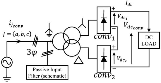
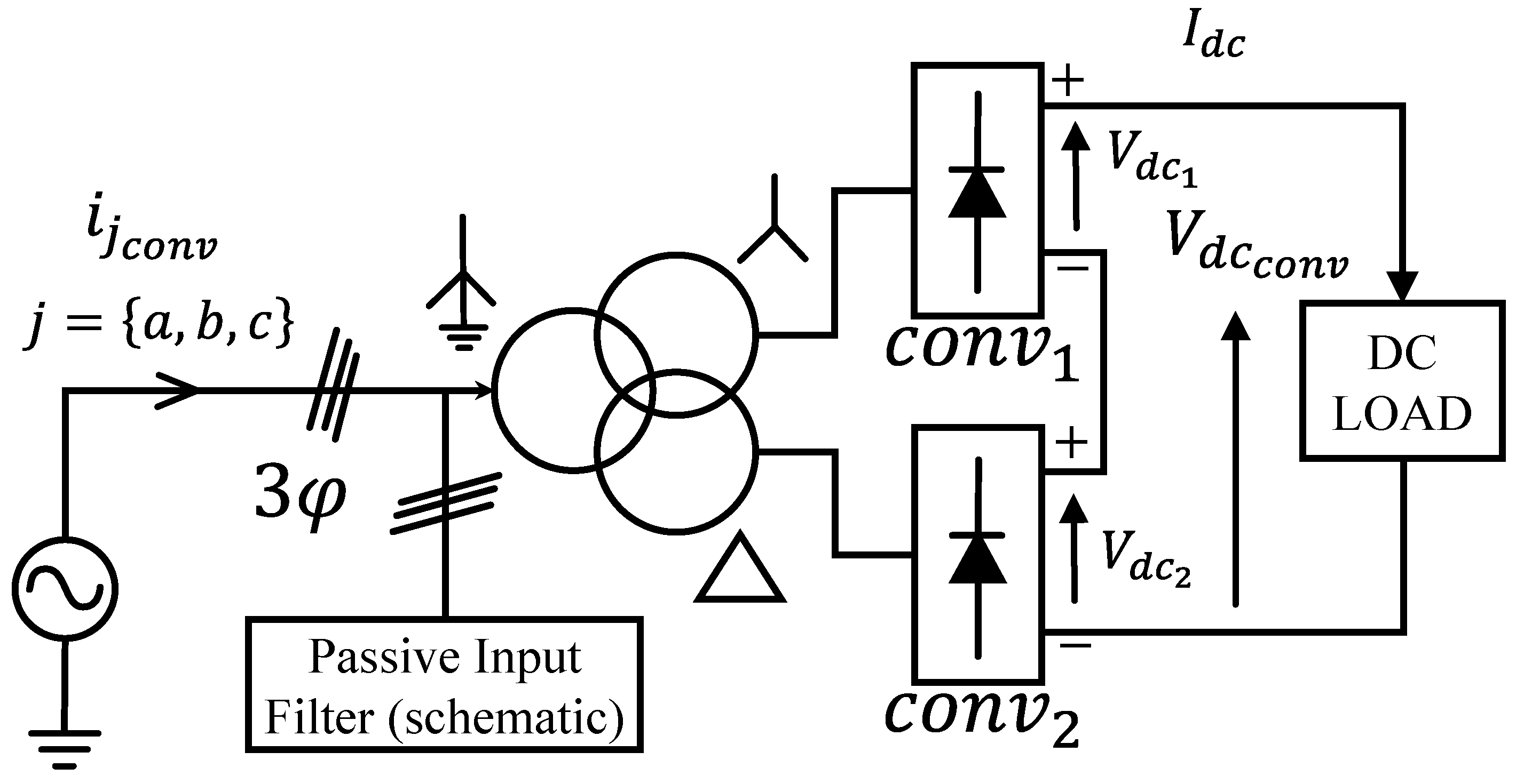
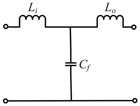
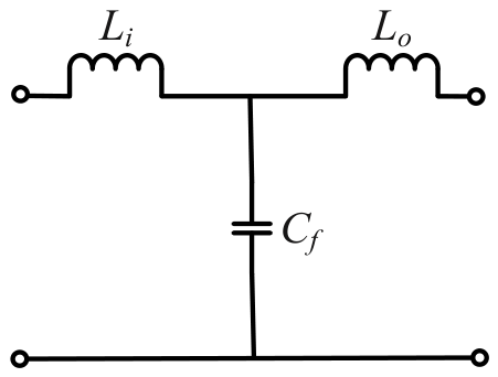
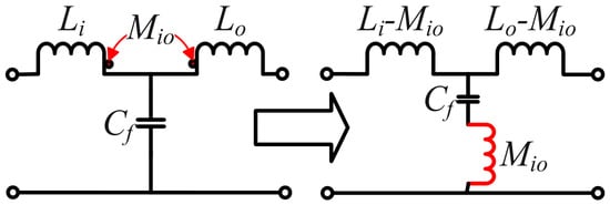
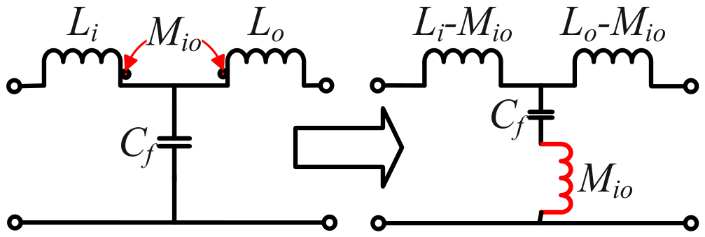
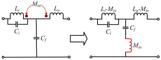
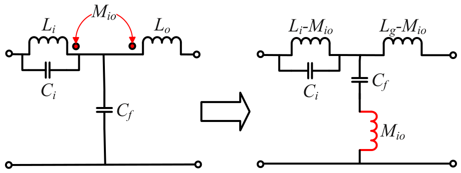
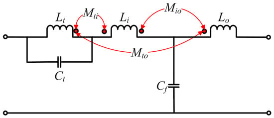
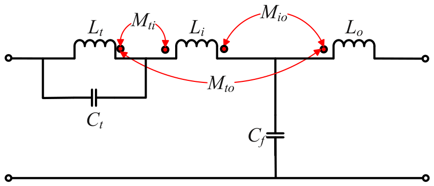
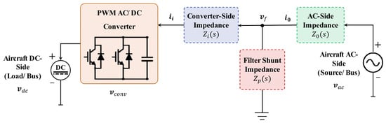
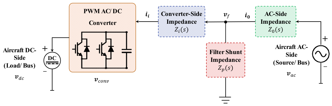
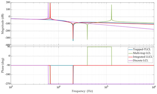
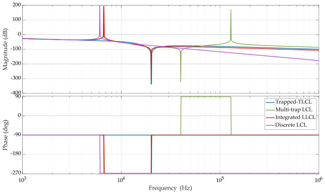
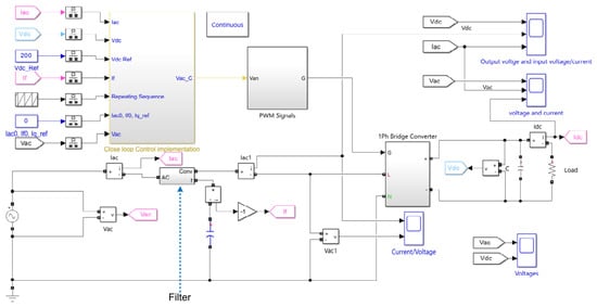
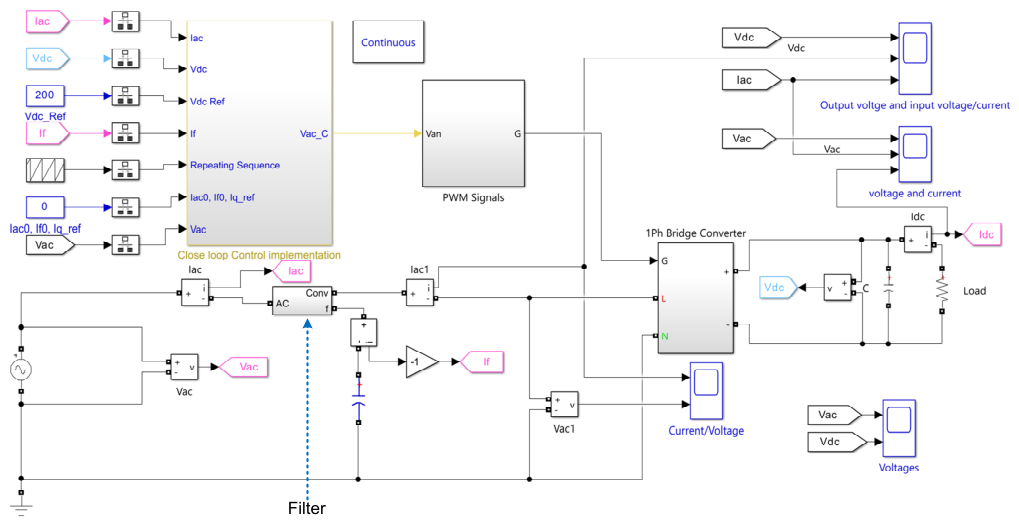
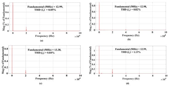
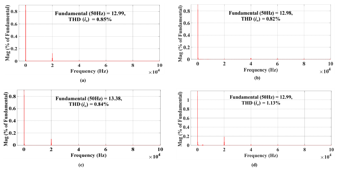
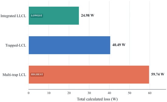
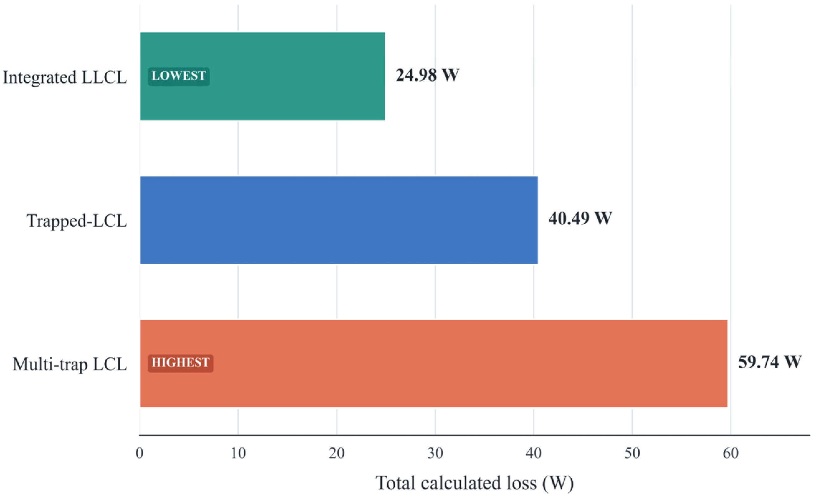
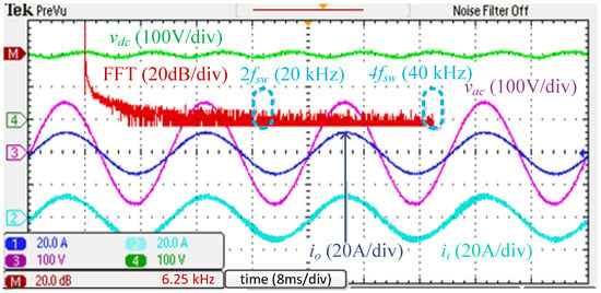
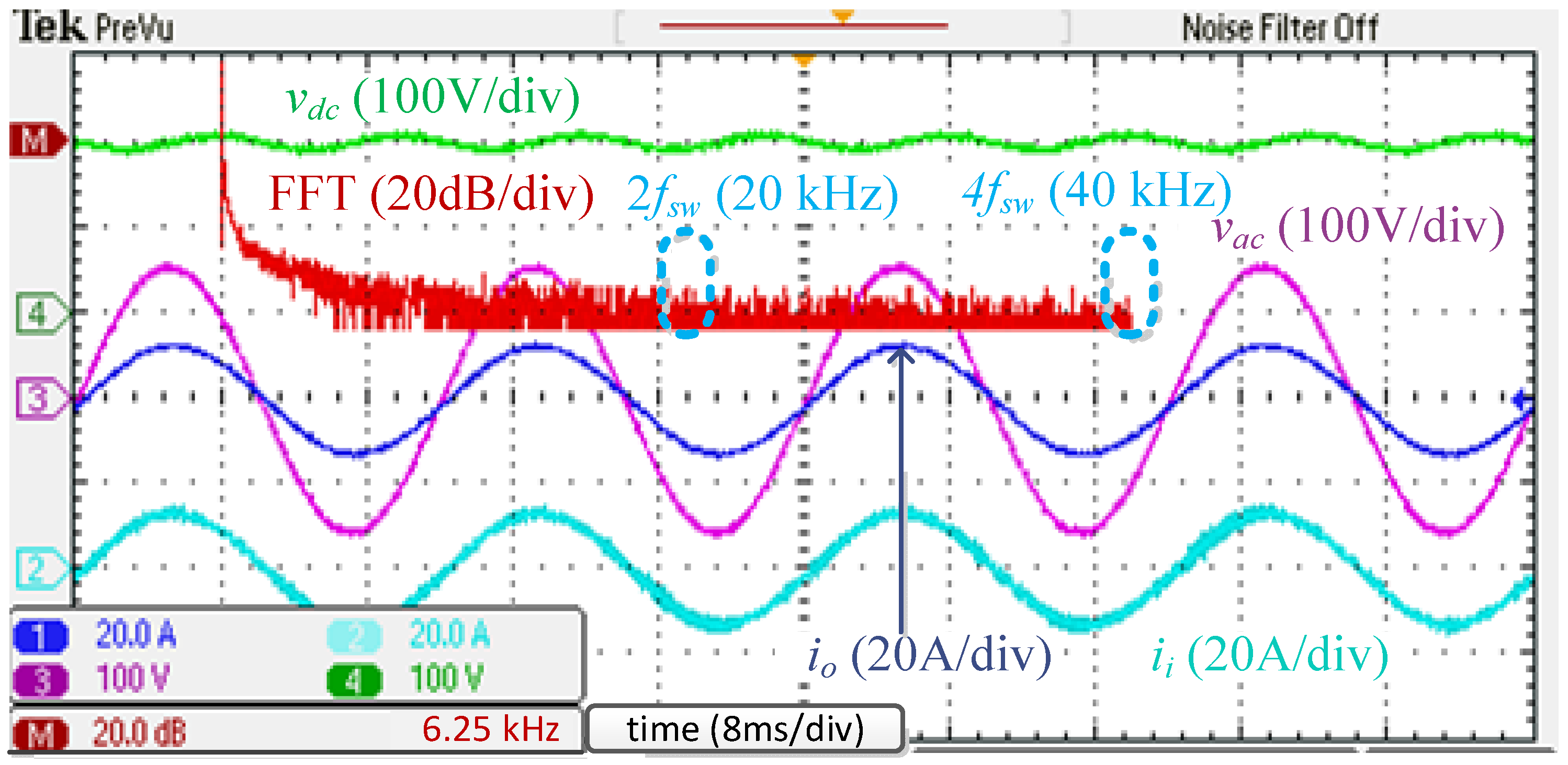
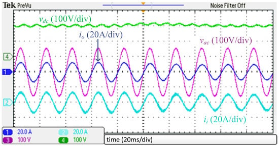
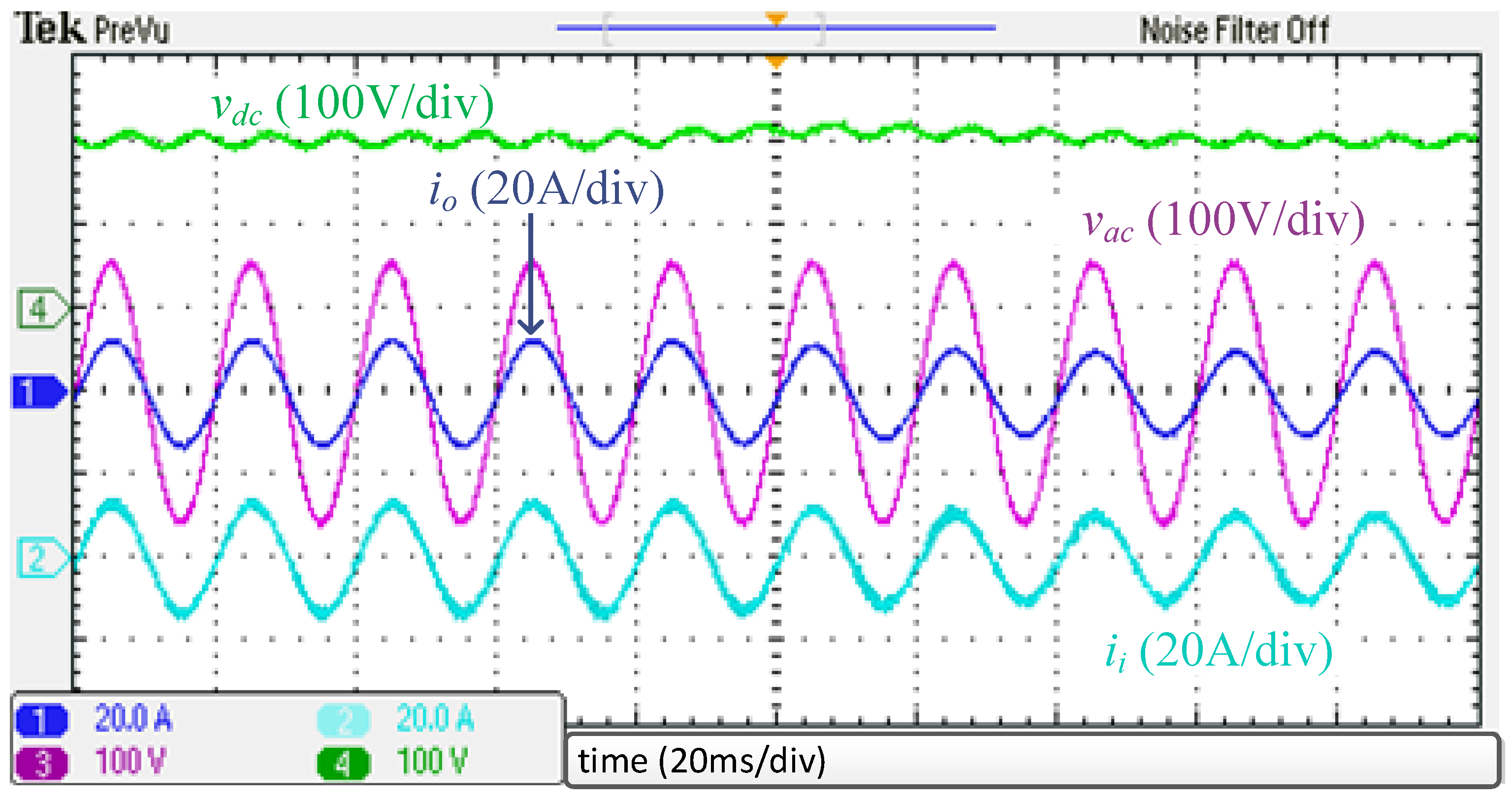
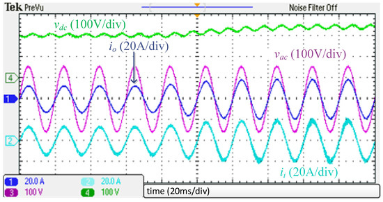
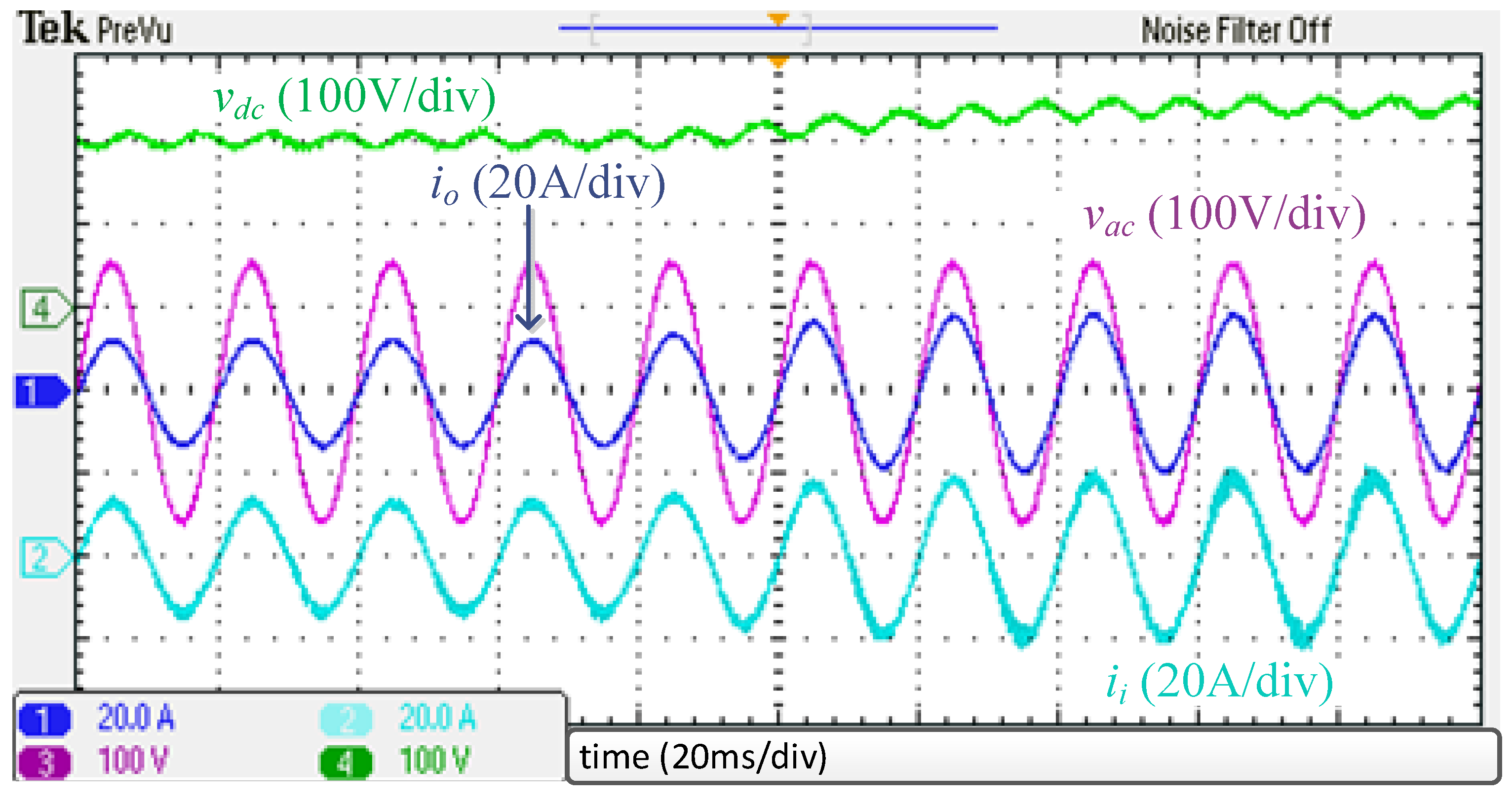
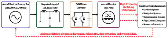
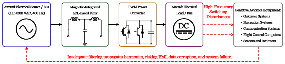

Disclaimer/Publisher’s Note: The statements, opinions and data contained in all publications are solely those of the individual author(s) and contributor(s) and not of MDPI and/or the editor(s). MDPI and/or the editor(s) disclaim responsibility for any injury to people or property resulting from any ideas, methods, instructions or products referred to in the content. |
© 2026 by the authors. Licensee MDPI, Basel, Switzerland. This article is an open access article distributed under the terms and conditions of the Creative Commons Attribution (CC BY) license.