


Abstract
This paper presents a G-Agent, a large language model (LLM)-driven multi-agent framework that automates the optimization workflow for an axisymmetric cavity-based scramjet combustor. The framework integrates a supersonic compressible reacting flow solver with the Qwen3-VL-2B-Instruct model. It consists of four specialized agents: Interactor, Runner, Corrector, and Optimizer. The Interactor parses user requirements and generates simulation input files. The Runner manages mesh generation, solver configuration, and simulation execution. The Corrector diagnoses failed cases by analyzing fault logs and applies corrective actions. The Optimizer coordinates the optimization process using a trust-region response surface method to maximize thrust. The framework employs Latin hypercube sampling (LHS) to explore the design space defined by three key geometric parameters: isolator length, cavity depth, and fuel injector position. Without manual intervention beyond initial specifications, the G-Agent successfully conducted multiple optimization iterations. Starting from a baseline thrust of 489.4 N, the optimized configuration achieved 523.5 N after three iterations, reaching a relative improvement of 6.97%. Our proposed agent achieves closed-loop control of the entire optimization process, significantly lowering the technical barrier and human effort in scramjet combustor design.
1. Introduction
Due to its high reliability and excellent performance in hypersonic flight environments, the scramjet has become the primary choice for hypersonic vehicle propulsion systems [1,2]. In recent years, researchers have conducted in-depth studies on scramjet infrared radiation [2], fuels [3,4], combustion mechanisms [5,6,7,8], ignition methods [5,6,7], and fuel distribution and injection strategies [8,9]. Furthermore, the configuration of the combustor has a decisive influence on the overall performance of the engine [10,11,12].
In the early stages of scramjet research, experimental methods were the primary means of investigation. To achieve accurate observation and measurement of supersonic combustion flow fields, many researchers have improved experimental techniques for scramjets [13,14,15,16,17]. These studies aim to reduce measurement interference with the combustion flow field and expand the range of measurable physical quantities. However, cost and technical limitations continue to constrain the advancement of experimental methods [18]. Scramjet combustion tests typically require customized test sections. Data obtained through intrusive measurement techniques are often very limited. Moreover, the response rate of non-intrusive methods is constrained by equipment capabilities. As engine operating conditions advance toward higher Mach numbers and wider speed ranges, investigating combustion flow field data in scramjet combustors via experimental means faces increasing challenges.
Consequently, many researchers have turned to computational fluid dynamics (CFD) methods to optimize the design of scramjet combustor configurations [19,20,21], investigate combustion mechanisms [19,20,21], and study the effects of different geometric layouts on scramjet combustion performance [19,21]. CFD methods function as critical tools for scramjet optimization and validation by significantly accelerating the engine design process. However, the high computational cost required for numerical calculations and the extensive manual effort involved in preparing numerical simulations remain substantial time costs in scramjet design optimization [22]. Currently, many researchers are attempting to introduce artificial intelligence methods such as deep learning (DL) into the scramjet design optimization workflow [23,24]. Progress has been made in areas such as flow field data prediction [25,26,27,28,29,30,31,32,33,34] and modal identification [35,36]. However, such models often require large amounts of data for training before they can be used effectively. The requirement of high-fidelity data prevents DL methods from being applied to engineering practice. Moreover, when using deep learning methods to predict the flow field within a scramjet combustor, the reliability and accuracy of the predicted data still lag behind those of CFD numerical simulation data. Therefore, these methods cannot yet effectively replace traditional numerical approaches in scramjet design.
In recent years, large language models (LLMs) have demonstrated powerful text processing capabilities [37] leading to breakthroughs in the field of artificial intelligence [38,39]. Recent research indicates that LLMs have the potential to accelerate scientific discovery through automation. The information-gathering and reasoning capabilities of LLMs have been validated in fields such as molecular property prediction, molecular generation and synthesis prediction [40,41], medical diagnosis and report generation [42,43,44], complex architectural modeling [45,46], and large-scale equipment performance monitoring [47]. Despite the limitations posed by hallucination issues [48] and ambiguity characteristics [49], researchers have begun integrating LLMs into existing CFD solving frameworks and attempting to solve parameterized problems [50,51].
Furthermore, many researchers are dedicated to integrating LLMs into the CFD solution process itself, aiming to reduce the level of manual intervention in CFD numerical simulations and improve the efficiency of the overall workflow. Pandey et al. [52,53] developed an LLM-controlled agent named successfully embedding Domain expertise is successfully embedded based on the open-source OpenFOAM solver. This agent is capable of performing various practical simulation tasks. Furthermore, high automation is realized in the key links of CFD numerical simulation. Covered functions involve zero-shot case setup, initial and boundary condition adjustment, turbulence model switching, and zero-shot code conversion. To enhance the performance of general-purpose LLMs in the specialized CFD domain, this study built a Retrieval-Augmented Generation (RAG) module based on the LangChain framework. By incorporating key information such as solver names, case types, and flow regimes, the module provides precise supplementation of CFD domain knowledge. The study also investigated the efficiency of different LLMs in generating complex fluid dynamics cases and the reasoning capabilities of locally deployed LLMs with fewer parameters. Addressing the limitations of RAG methods in terms of transfer learning and model generalization performance, Dong et al. [54] constructed the NL2FOAM dataset. NL2FOAM comprises 28,716 paired natural language descriptions and corresponding OpenFOAM configurations. This work fine-tuned the Qwen2.5-7B-Instruct model using Low-Rank Adaptation (LoRA) technology, successfully embedding Domain expertise into the LLM’s model parameters directly. Validation showed that this method significantly reduces token overhead and markedly improves the first-pass success rate of case generation. Although both studies made progress, the problems addressed were still limited to OpenFOAM tutorial cases. The application of LLMs to the solution of complex flow fields was not achieved. To tackle this issue, Xu et al. [55] proposed CFDAgent, a zero-shot, language-guided multi-agent framework. The model decomposes the CFD numerical simulation workflow into three distinct agents controlling pre-processing, numerical solving, and post-processing. The pre-processing agent integrates the text-to-3D hybrid diffusion model Point-E to autonomously generate point clouds and convert them into computational meshes. This implementation partially automates the mesh generation process for practical engineering problems. The framework can complete flow simulations around complex real-world geometries using simple text prompts, significantly lowering the technical barrier to CFD analysis. Wang et al. [56] studied different LLMs by selecting typical problems to explore their capabilities in utilizing, learning, and creating knowledge when solving CFD problems. The analysis indicated that non-reasoning models could only solve problems addressable by existing numerical methods. But reasoning models could solve problems requiring novel numerical methods provided by the user to some extent. For problems unsolvable by existing numerical methods within the model’s knowledge, such as solving ill-conditioned Hilbert systems of linear algebraic equations, none of the models could provide the correct solution. Therefore, the autonomous knowledge exploration and innovation capabilities of LLMs still require strengthening. Overall, current research on the integration of LLMs and CFD workflows remains at the methodological exploration stage. The technical advantages of LLMs have yet to be applied to specific fluid mechanics research problems.
Inspired by the aforementioned studies, this paper proposes an LLM-driven agent framework designed to enhance the automation level of the configuration optimization workflow for a scramjet cavity combustor. Thereby, it considerably reduces the technical expertise barriers and the degree of manual intervention required for this work.
This paper presents the G-Agent, an LLM-driven agent framework based on a CFD supersonic compressible reacting flow solver and the Qwen3-VL-2B-Instruct model. Our aim is to automate the configuration optimization workflow for a scramjet cavity combustor. It should be noted that thrust is adopted here as the optimization target for demonstration purposes. The proposed framework is by no means limited to this single metric; it can be readily extended to optimize other performance parameters—such as combustion efficiency, total pressure recovery, or outlet flow uniformity—or to handle multi-objective optimization tasks with minimal modification. The framework employs four collaborative agents to handle requirement decomposition: the interactor, the runner, the corrector and the optimizer. Isolator length, cavity depth, and fuel injection port location are the core optimization parameters. A Latin Hypercube Sampling (LHS) method is adopted to cover the parameter space. Numerical simulations are conducted using the Reynolds-Averaged Navier–Stokes (RANS) method coupled with the Shear Stress Transport (SST) turbulence model. By leveraging the in-context learning capabilities of the LLM, the framework achieves closed-loop control of the entire configuration optimization workflow. This approach aims to lower the professional barrier and manual cost while enhancing the efficiency of configuration optimization.
The remainder of this paper is organized as follows. Section 1 elaborates on the research significance of scramjets and the limitations of experimental and traditional numerical methods. The current status of LLM applications in the CFD field is reviewed. Then, the research objective of integrating LLMs with CFD to automate combustor configuration optimization is defined. Section 2 describes the methodology. It details the multi-agent architecture of G-Agent and the core model selection. The core model selection specifies the combustor geometric parameters and optimization ranges. The section also presents the governing equations, the mesh generation strategy, and the computational setup employed in the numerical simulations. Section 3 presents and discusses the results. It analyzes the parameter generation performance of the LLM under the in-context learning mode. It validates the influence of configuration on thrust through Latin Hypercube Sampling and iterative optimization. It also illustrates the optimization trends across multiple iteration rounds. Section 4 summarizes the research findings, core innovations, and limitations, and proposes directions for future research.
2. Method
2.1. LLM Agent System
The in-house code of the CFD solver employed in this study is a supersonic compressible reacting flow solver developed by the College of Aerospace Science and Engineering, National University of Defense Technology, Changsha, China. It adopts the Flamelet/Progress Variable (FPV) combustion model and is accelerated by Graphics Processing Units (GPUs). It is capable of efficiently and robustly simulating supersonic turbulent combustion flows. The reliability and accuracy of this code have been extensively validated in previous studies [20,57,58,59]. Qwen3-VL-2B-Instruct is the third-generation lightweight multimodal vision-language model from Tongyi Qianwen, featuring approximately 2 billion parameters (2B). It is fine-tuned with instructions to enhance its understanding of and responsiveness to human commands. This model supports joint image and text input. It possesses multimodal understanding capabilities including image captioning, Optical Character Recognition (OCR), and chart parsing. At the same time, it balances inference efficiency, making it suitable for deployment in resource-constrained environments. In this study, the G-Agent framework is developed based on the in-house solver and the Qwen3-VL-2B-Instruct model to achieve a high degree of automation in the design optimization workflow for scramjet engines.
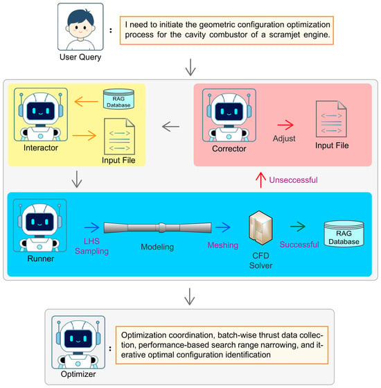
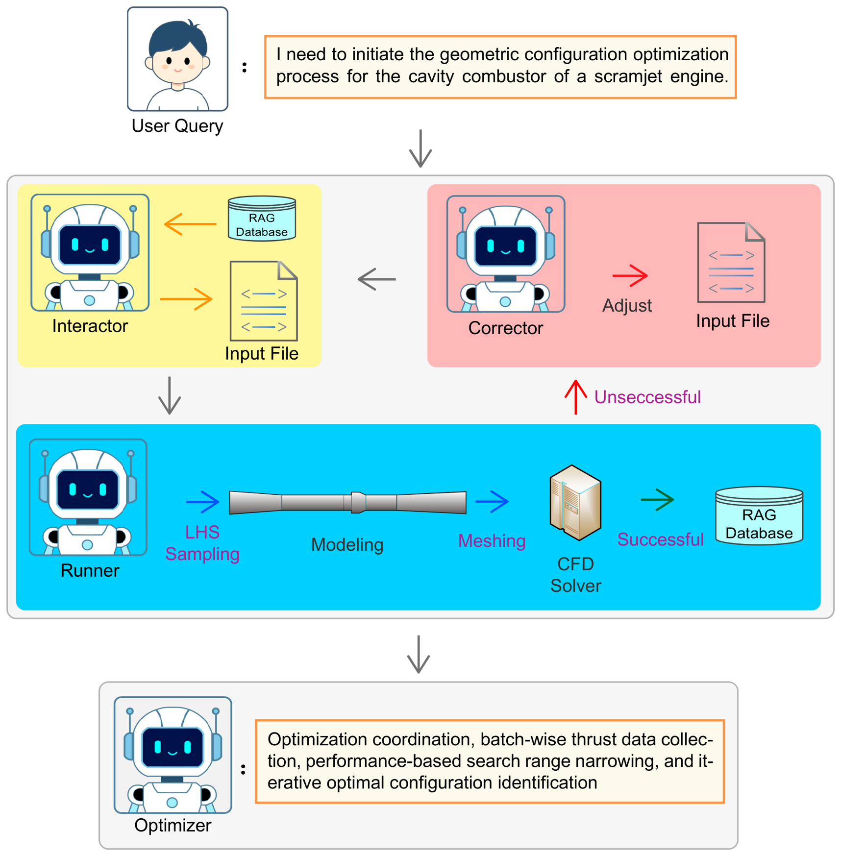
Figure 1 illustrates the architectural design of G-Agent. The primary tasks of the workflow are decoupled and controlled by four distinct agents. The interactor, the runner and the corrector process the specific simulation case, while the optimizer coordinates the overall optimization progress. For the sake of brevity and clarity, certain implementation details are omitted in the algorithmic description.
Figure 1.
Architecture Design of the Agent Framework.
The interactor initiates the dialog and confirms the user’s specific requirements for the simulation and optimization of a scramjet cavity combustor, as well as the technical parameters for the computational effort. In the first phase, the user interacts via a conversational interface. If the user indicates a need for CFD simulation, the LLM begins assisting with the simulation process. Through dialog, the interactor guides the user to specify the target object. For instance, the case can be defined by name/description, by uploading a reference image of the object, or by providing an existing 3D mesh file. Simultaneously, the user is directed to define the operating conditions of the scramjet, specifically the physical parameters required for the simulation (such as pressure, temperature, Mach number, and species fractions) and the numerical parameters (such as CFL number, time step size, number of iterations, and scheme type). Subsequently, the user is prompted to specify the combustor configuration parameters of interest. This Agent guides the user step-by-step to clarify requirements and compiles the formatted input files.
The runner receives the output from the interactor and identifies the specific configuration parameters of the scramjet cavity combustor to be optimized. Then it samples these parameters within the optimization space and generates parametric combustor configurations. Subsequently, it invokes meshing tools to perform grid generation and defines the boundary conditions for the case. Once the geometry and simulation parameters are determined, the framework automatically generates the necessary configuration files for the CFD solver. The runner then parses the solver parameters, launches the CFD solver, and executes the numerical simulation. In order to further enhance the Interactor’s capability in generating cases, the runner records the data and stores it in the RAG database if the computation is successful. If a fault occurs, the case is submitted to the corrector.
The corrector receives the log files of failed cases and classifies the fault types. For diverged cases, it appropriately reduces the CFL number. For cases with negative values, it performs flow rate checks and verifies the chemistry library and inlet boundary conditions. After the modified case is resubmitted for computation, if a fault still occurs, the geometric parameters and diagnostic results are recorded, vectorized, and stored in the RAG knowledge base. When generating the next batch of sample points, similar failure cases are retrieved by comparing candidate parameters. If a severe fault such as negative thrust or divergence is matched, the parameters are automatically perturbed to proactively avoid the failure region.
The optimizer coordinates the entire framework to carry out the configuration optimization of the scramjet combustor. Upon completing one batch of simulations, the optimizer collects statistics on the engine thrust values obtained and shrinks the search range for the next iteration based on the performance of existing sample points. Following several iterations, the optimal configuration is ultimately obtained.
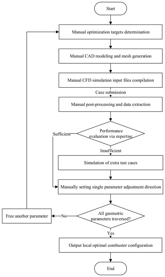
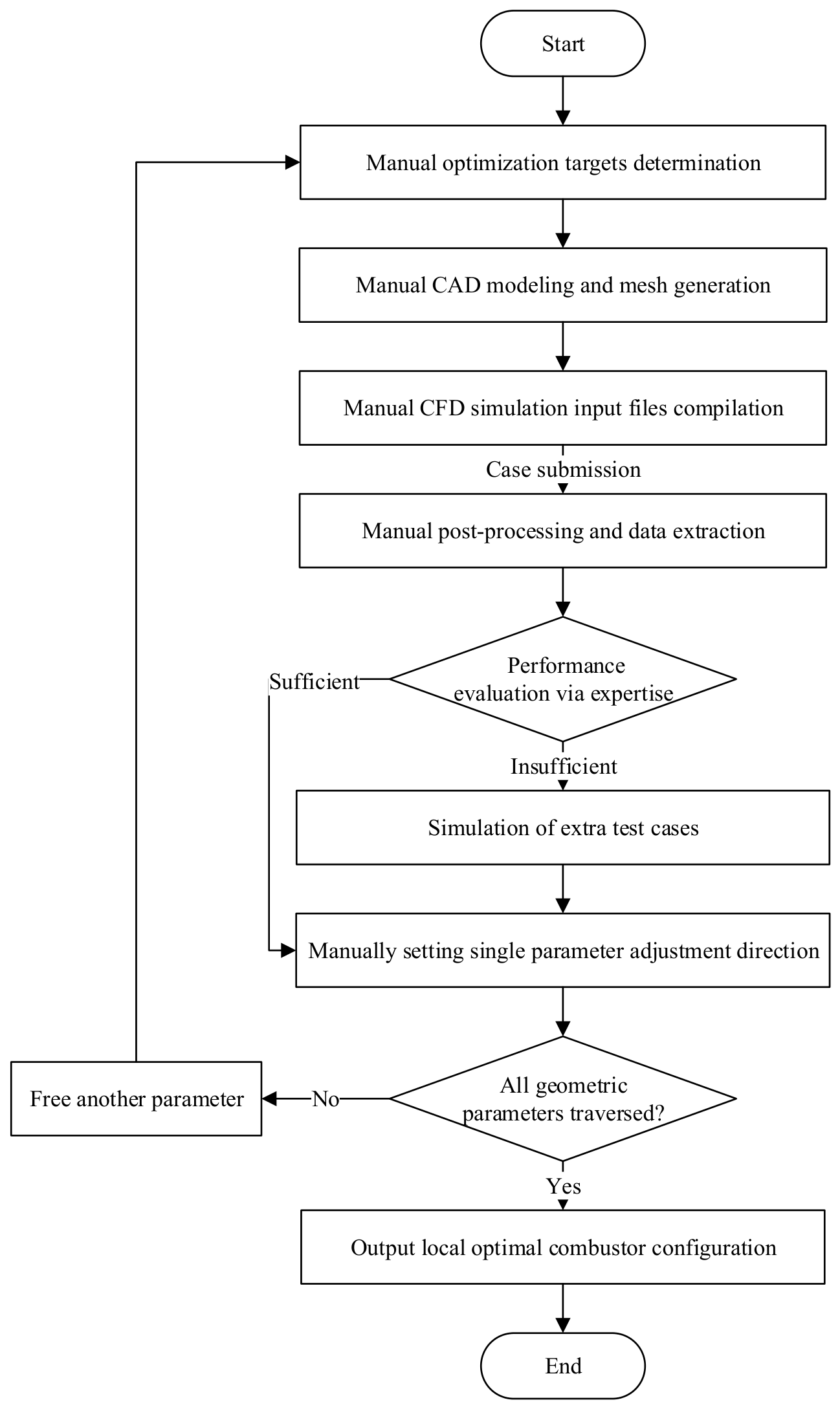
In the conventional optimization practice for scramjet combustors shown in Figure 2, engineers manually build geometries, generate meshes, and run simulations one by one, and adjust parameters relying on personal domain-specific experience. This typical workflow often optimizes one parameter at a time while freezing others, which easily traps the solution in local optima, and heavily depends on continuous human operations covering pre-processing, simulation submission, post-processing and iterative parameter tuning. In contrast, our G-Agent framework automates the full-loop decision-making process via an LLM-driven multi-agent system. The numerical optimiser serves only as one modular component, and the multi-agent system undertakes tasks originally completed by human experts, including target understanding, case generation, and fault diagnosis for iteration control. It samples multiple parameters simultaneously with Latin Hypercube Sampling and iteratively shrinks the design space through response-surface modeling to mitigate local-optimum risks. Equipped with an embedded RAG knowledge base, the framework can absorb, accumulate and reuse existing domain knowledge rather than relying merely on objective-function feedback. This design substantially cuts expert intervention and manual workload.
Figure 2.
Traditional optimization workflow.
2.2. Retrieval-Augmented Generation
Qwen-VL-2B is a lightweight multimodal vision-language model open-sourced by Alibaba Tongyi Lab. It is suitable for local deployment, edge devices, and low-resource scenarios. The model features 2 billion parameters and a 32K token context window. Deployment requires about 8 GB of video memory. This modest resource footprint facilitates flexible construction of the optimization framework.
Localized models lack domain-specific experience and are prone to offering suggestions that deviate from physical plausibility. They are unable to retain memory of historical failures because each conversational session is isolated. Consequently, it is difficult for such models to derive experiential insights from failed computational cases to further enhance operational performance. There are generally two approaches for injecting specialized knowledge into general-purpose LLMs: Retrieval-Augmented Generation (RAG) and Low-Rank Adaptation (LoRA). Applying LoRA to an LLM requires building a dataset in advance and performing high-quality data annotation. Moreover, real-time updates are not feasible. In engineering problems, the requirement of preparing data in advance raises the barrier for model deployment. Therefore, RAG is considered for accomplishing the task of specialized knowledge injection.
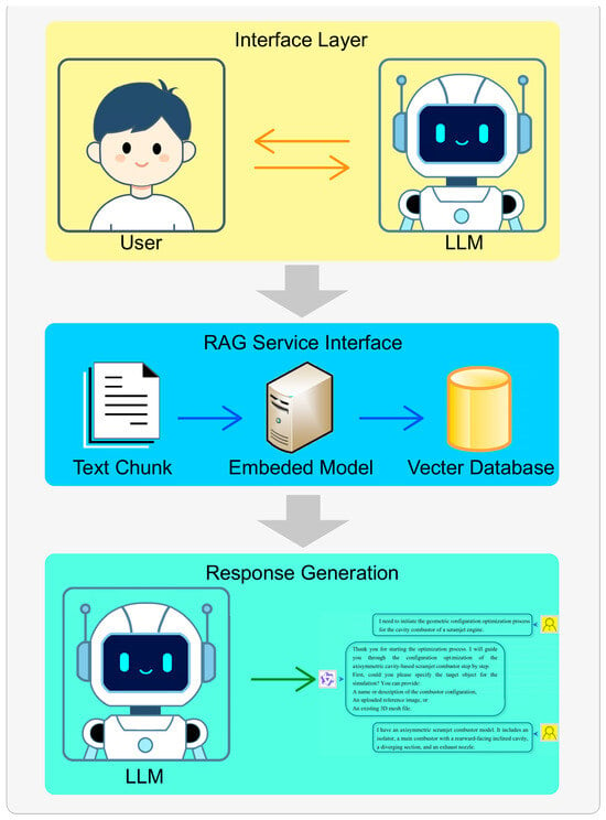
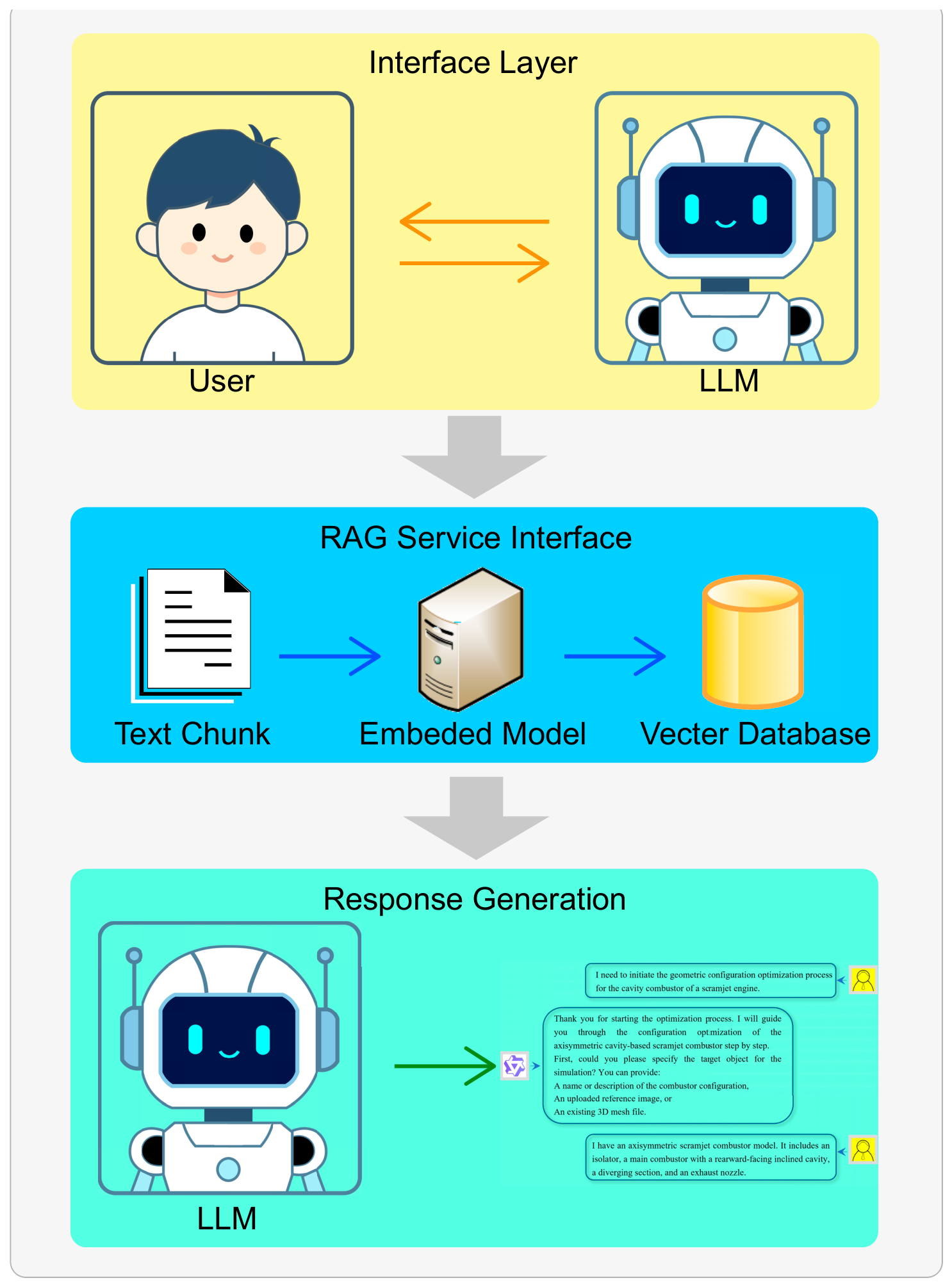
As illustrated in Figure 3, the introduction of domain knowledge via RAG serves to optimize prompt engineering and yield more precise outcomes [60] accordingly. This functionality is implemented based on the LangChain framework [61,62]. Although large language models (LLMs) possess general knowledge reasoning capabilities, their performance in specialized tasks is substantially improved following the incorporation of domain-specific resources.
Figure 3.
RAG Architecture.
Based on the engineering experience of CFD simulation practitioners, the empirical rules that the model is required to know are organized into text chunks. Each rule is presented as a separate paragraph and controlled to a length of 100–300 characters. Examples include:
Rule 1: If the residual curve continues to oscillate or decreases very slowly after 100,000 iterations, the CFL number may be appropriately reduced (to between 0.05 and 0.1) to enhance numerical stability.
Rule 2: For hypersonic flows (Ma > 3), it is recommended that the CFL number not exceed 0.5; otherwise, the solution is prone to divergence.
Rule 3: The step size for angle of attack adjustments should not exceed 0.2 degrees per iteration to prevent abrupt changes in the flow field that could lead to solution divergence.
Rule 4: The static temperature and static pressure must satisfy the ideal gas equation of state; adjustments to these parameters should maintain physical consistency.
Rule 5: In the event of solution divergence, first inspect the mesh quality; subsequently, reduce the CFL number to below 0.1 and adopt an explicit numerical scheme.
Rule 6: For combustion reactions involving hydrogen (H2), the finite-rate chemistry model requires verification that the chemical kinetics library file Chemical_Lib.json is correctly loaded.
Rule 7: A residual drop below 1 × 10⁻⁴ is generally considered indicative of convergence. If convergence is not achieved by the maximum iteration limit, the number of iterations should be increased or the under-relaxation factors adjusted.
…
The sentence-transformers/paraphrase-multilingual-MiniLM-L12-v2 model is embedded in the architecture. It gives the system the ability to convert geometric parameter values of candidate design points into natural language representations. When generating recommendations, the model retrieves expert rules that are most similar to the current state. This substantially improves the plausibility and relevance of the generated suggestions. As more optimization calculations are performed, successfully implemented parameter adjustments are automatically added to the knowledge base. This facilitates continuous learning. Failure cases are also stored. Each record includes the specific geometric parameter combination, the failure type, and the corrective actions taken. During subsequent parameter generation, the system automatically queries the case base to avoid repeating known failure modes. Moreover, the LLM can synthesize retrieved cases to identify hazardous regions in the parameter space and proactively suggest revisions to the design space boundaries.
2.3. Computational Methodology
2.3.1. Numerical Method
The in-house solver code [63] employed in this study is a supersonic compressible reacting flow solver developed by the National University of Defense Technology. The solver is accelerated by Graphics Processing Units (GPUs) to enable efficient and robust simulation of supersonic turbulent combustion flow fields. The program is primarily developed in C++, while the GPU implementation utilizes the CUDA architecture [64]. The reliability and computational accuracy of this code have been extensively validated in prior studies [58].
To balance computational efficiency and accuracy, this study adopts the Reynolds-Averaged Navier–Stokes (RANS) methodology to capture the primary features of the flow field. The Favre-averaged conservative form of the RANS governing equations is expressed as follows:
where
where denotes the time coordinate, and represents the spatial coordinate. , , , , , , , and denote the filtered density, velocity components, total energy, mixture fraction, progress variable, enthalpy, pressure, temperature, and variance of the mixture fraction, respectively. and represent the viscous stress tensor and the Reynolds stress tensor, respectively. The unnormalized progress variable , representing the Favre-filtered sum of major combustion-product species, is directly solved by its own transport equation together with the mixture-fraction transport equation. To obtain the 0-to-1 bounded input for flamelet table lookup, the normalized progress variable is computed via standard min-max normalization:
where and correspond to the unnormalized progress-variable values under unreacted mixing state and fully burnt equilibrium state, respectively. By definition, denotes the unreacted mixture, and represents fully completed chemical reaction. Thermochemical properties including temperature, species mass fractions and reaction source terms are retrieved from the pre-constructed pressure-dependent flamelet database, using the Favre-averaged mixture fraction , mixture-fraction variance , and normalized progress variable as the lookup parameters. and denote the laminar dynamic viscosity and the turbulent eddy viscosity, respectively. and are the laminar and turbulent Schmidt numbers, both assigned a value of 0.5. is the turbulent Prandtl number, assigned a value of 0.9. The term with various subscripts represents the diffusion coefficients for different transport processes. is the specific heat capacity at constant pressure; and is the thermal diffusivity. To reduce computational cost, the transport equation for the mixture fraction variance is not solved in a complex manner in this study; instead, an algebraic model is adopted as a surrogate, with the model coefficient . The solver incorporates the SST model [65] for computing the turbulent eddy viscosity and turbulent kinetic energy . This model effectively accounts for flow characteristics in both near-wall separated regions and the mainstream region of the flow field and is widely employed in the prediction of supersonic turbulent flows. The corresponding transport equations and model coefficients can be referenced in the relevant prior literature [65,66].
In addition, future work will consider introducing high-resolution structure-preserving convection schemes (e.g., the ROUND schemes) into our in-house compressible reacting flow solver. Such schemes exhibit low numerical dissipation, favorable scalar structure preservation and reliable shock-capturing performance for supersonic flows. Although the open-source libROUNDSchemes library is implemented for OpenFOAM and cannot be directly imported into our present solver, developing similar discretisation modules will further improve the numerical accuracy of supersonic combustion simulations.
2.3.2. Axisymmetric Scramjet Combustor Model
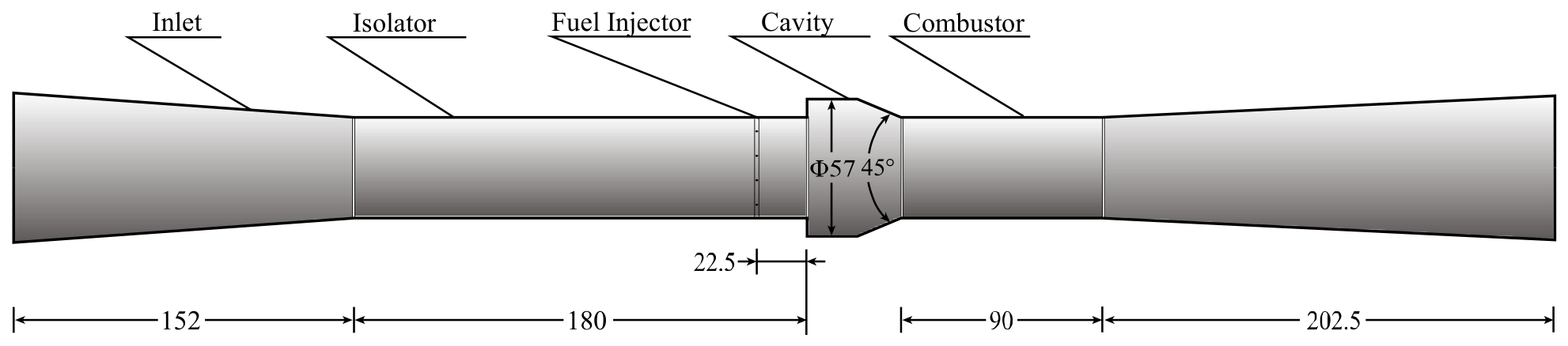
This study employs the axisymmetric scramjet combustor model developed by the University of Illinois [67]. The combustor model primarily consists of four sections: a constant-area isolator, the main combustor, a diverging section, and the exhaust nozzle. The main combustor features a cylindrical tube configuration with a rearward-facing inclined cavity, and the baseline configuration is illustrated in Figure 4. The specific injection and freestream inflow conditions are presented in Table 1.
Figure 4.
Geometric Model of the Cavity Combustor.
Table 1.
Freestream and Injection Parameters.
Three primary parameters are defined to characterize the configuration of the cavity combustor: the isolator length , the cavity depth , and the fuel injection port location . Within the initial design space, the range of is specified as 140 to 220 mm; ranges from 4 to 8 mm; and ranges from 18.5 to 26.5 mm. To minimize the number of selected geometric variables, the total length of the cavity combustor is held constant at 680 mm. When sampling the geometric parameters of the cavity combustor, the Solution Optimization Agent employs the Latin Hypercube Sampling method to ensure orthogonality and comprehensive coverage of the sampled data across the entire design space.
2.3.3. Grid and Independence Analysis
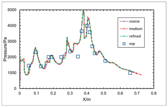
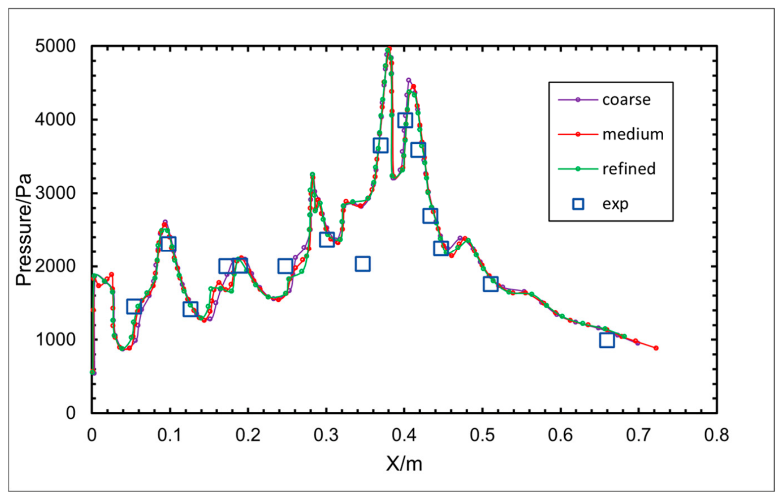
Runner imports the geometric modeling file into the parametric mesh generation program and discretizes the internal flow domain of the cavity combustor using a hexahedral mesh, as shown in Figure 5. To capture the flow and heat transfer characteristics within the boundary layer more accurately, mesh refinement is applied in the near-wall regions of the fluid domain. Meanwhile, ensuring that the value remains below 1 is critical for the iterative convergence of the viscous sublayer solution in the turbulence model. The value is typically governed by the first-layer cell height of the boundary layer mesh. Accordingly, the first-layer heights of the boundary layer mesh for the microchannel and the jet duct are set to 0.01 mm and 0.001 mm, respectively, with a mesh growth rate of 1.1 for both. The global mesh count is approximately 7.4 million cells. Local mesh refinement is applied in the near-wall regions, near the fuel injection port, within the cavity shear layer, and in areas with expected shock wave formations. A small first-layer cell height is adopted at the walls to accurately resolve the boundary layer, satisfying the low-Reynolds-number wall treatment requirements of the SST turbulence model. For the specific circular cross-section single-cavity configuration, a mesh independence study has been conducted in prior research [68]. Figure 5 [68] compares the numerical predictions of wall static pressure and exit Mach number against experimental measurements across three different mesh resolutions. The coarse, medium, and fine meshes correspond to cell counts of 7.4 million, 9.4 million, and 11.4 million, respectively. It can be observed that the results from the medium and fine meshes exhibit excellent agreement for both wall pressure and exit Mach number predictions, whereas the coarse mesh shows noticeable deviations. For instance, the pressure rise feature in the isolator region at approximately is not accurately captured by the coarse mesh due to its inability to resolve the shock structure adequately. Regarding the mainstream exit Mach number, the value computed by the coarse mesh is significantly lower than those obtained from the other two meshes. The medium mesh offers a suitable balance between computational cost and simulation fidelity for the reacting flow field. Based on the freestream Reynolds number of the model investigated in this study, the medium mesh resolution is ultimately selected for all subsequent computations.
Figure 5.
Comparison of Wall Static Pressure Distributions between Experimental Combustion Flow Field and Numerical Results Obtained with Different Mesh Resolutions.
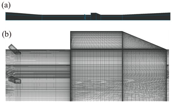
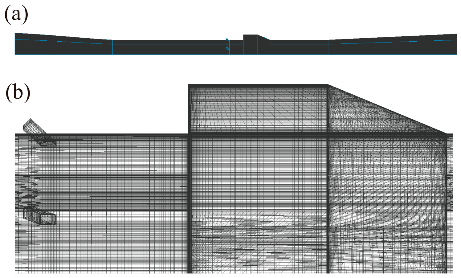
The structured mesh generated according to the geometric configuration of the cavity combustor is shown in Figure 6.
Figure 6.
Computational Mesh of the Cavity Combustor. (a) global mesh; (b) Partial details of the cavity.
2.4. Optimization Method
2.4.1. Response Surface Model
The Response Surface Model (RSM) is a class of surrogate model methods that constructs an approximate input–output function using a small number of sample points. The polynomial response surface is its most fundamental and classical form, which is suitable for solving low-dimensional problems. The mapping between the configuration parameters of a scramjet combustor and the thrust can be regarded as a black-box model. Therefore, a polynomial response surface can be adopted to approximate this mapping. The design space of the parameters is:
where
In the -th iteration, a second-order polynomial response surface model is constructed based on all existing sample points , where the coefficients are obtained by least squares fitting:
Let the search region after the -th iteration be (with the initial region ), and the width of its -th dimension be defined as: . The maximum point of the response surface is then found within the current region via random sampling:
Then, with as the center, the region is shrunk by a contraction factor . To prevent the optimization range from shrinking too rapidly and converging to a local optimum, we set in this work:
That is, the new region is a hypercube centered at with edge lengths , truncated to the global boundary .
Within the shrunk region , Latin Hypercube Sampling (LHS) is adopted to generate new sample points . The thrust values of these points are computed using the CFD solver, and these new points, along with their predicted values, are added to the dataset:
The maximum value among the newly added points in this iteration is recorded:
To ensure the algorithm performs at least iterations, the first iterations are forced to continue. Starting from the -th iteration, the difference between the maximum value of the current iteration and that of the previous iteration is calculated:
If with , the optimization is terminated; otherwise, the iteration continues until the preset maximum number of iterations is reached.
2.4.2. Latin Hypercube Sampling
Latin Hypercube Sampling (LHS) is an efficient stratified random sampling technique. Its core principle is to divide each input variable’s value range into non-overlapping intervals. Here denotes the number of sampling points. One sample point is randomly selected from each interval. The sampled values of each variable are guaranteed to be non-repetitive across the entire sample set. The result is a dataset that covers the full parameter space with uniform sample distribution. LHS is especially suitable for high-dimensional parameter spaces. It captures parameter correlations and global distribution characteristics with a small sample size. Therefore, it is widely used in engineering optimization and numerical simulations such as CFD case generation.
Compared with other sampling and optimization algorithms, LHS offers remarkable advantages. Unlike simple random sampling, LHS avoids sample aggregation or poor local coverage. It achieves better parameter space coverage with fewer samples. Unlike grid sampling, LHS does not need to traverse all parameter combinations. This greatly reduces computational cost in high-dimensional scenarios while maintaining key interval coverage. In combined applications with optimization algorithms, LHS is commonly adopted as an initial sample generation tool for global optimization algorithms like genetic algorithms and particle swarm optimization. Its uniformly distributed samples provide more comprehensive initial search baselines. This improves optimization efficiency and the probability of finding the global optimum. In contrast, traditional optimization algorithms that rely on random initial samples often fall into local optima. When combined with surrogate models such as response surface methods, LHS samples can fit the mapping between parameters and objective functions more accurately. They also enhance surrogate model prediction accuracy. Thus, LHS delivers better performance than conventional random or local sampling methods.
3. Case Verification
3.1. Effect of LLM on Case Generation
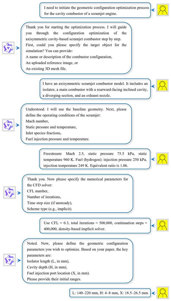
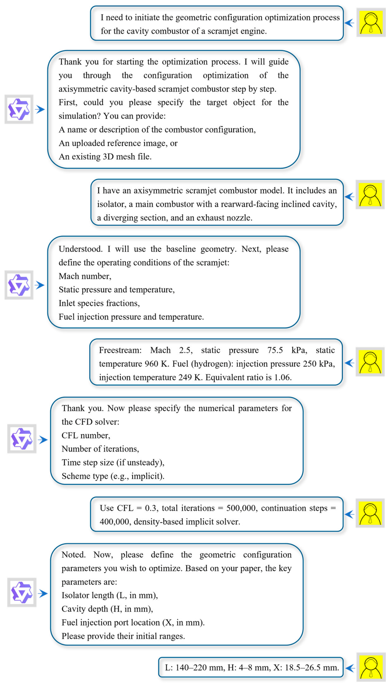
Figure 7 illustrates the interaction between a user and the G-Agent framework. The user initiates the process by requesting geometric configuration optimization. The Interactor agent subsequently guides the user through a structured workflow. It first asks for the target object definition, including a geometry description or mesh file. Next, it collects operating conditions such as Mach number, pressure, and temperature. Numerical parameters, including CFL number and iteration count, are then requested. The agent further prompts the user to specify the three geometric design variables: isolator length, cavity depth, and injector position, along with their initial ranges. After confirming the setup, the Interactor launches the Runner, Corrector, and Optimizer agents. Progress updates are provided after each batch. The interaction concludes with reporting the optimal configuration and exporting results. The entire dialog demonstrates closed-loop, stepwise guidance without manual intervention beyond initial inputs.
Figure 7.
Example of agent interaction.
During case generation, the Interactor retrieves the most relevant rules via semantic similarity. This improves the plausibility and accuracy of the generated solver input files. The RAG system also stores historical failure cases, including parameter combinations and fault types. When generating new cases, the Interactor queries this knowledge base to avoid known failure modes. Consequently, the RAG-enhanced Interactor produces more reliable simulation setups with reduced manual intervention.
3.2. Numerical Verification
The mesh file is imported into the numerical simulation software. The mesh quality is first inspected to ensure that no negative-volume cells exist within the computational domain. Given that the fluid within the cavity combustor is a high-speed compressible gas, a density-based implicit solver is selected by employing the implicit formulation to ensure iterative stability. The freestream inflow conditions are set to a Mach number of 2.5, a static pressure of 75.5 kPa, and a static temperature of 960 K. The fuel injection pressure is set to 250 kPa, and the fuel injection temperature is 249 K. A no-slip boundary condition is imposed on the walls, with a wall temperature fixed at 300 K. The CFL number and the CFL number for continuation runs are both set to 0.3. The number of continuation steps is set to 400,000, and the total number of computational steps is set to 500,000. In this study, ‘computational steps’ denotes the total number of iterations allocated for the entire simulation, while ‘continuation steps’ refers to the iterations performed in each continuation sub-run when the solver is restarted from a previous solution. The simulation is carried out in two stages: the first 100,000 steps are dedicated to a cold-flow (non-reacting) calculation to establish a stable flow field, after which ignition is triggered and the reacting flow continues. Based on our convergence monitoring, the cold-flow stage typically converges within 100,000 steps, and the reacting stage reaches steady convergence after approximately 200,000 additional steps. Considering the complexity of residual-based criteria due to the order-of-magnitude differences between cold and reacting stages, we adopted a fixed-step strategy with computational steps set to 500,000 and continuation steps to 400,000, values sufficiently large to ensure convergence across all tested configurations.
Following the numerical simulations, a dataset is generated with the isolator length , cavity depth , and fuel injection port location as inputs, and the resulting thrust as the output. All simulations were conducted on a server with 8 NVIDIA RTX 4090 GPUs, with each case consuming approximately 5.56 h of wall-clock time on average. The entire optimization campaign, involving 300 CFD cases, therefore required about 1668 GPU-hours in total, corresponding to roughly 9 calendar days when executed in parallel across the 8 GPUs. A partial excerpt of this dataset is presented in Table 2.
Table 2.
Sample Excerpt of CFD Data.
Through numerical simulation, the contour distributions of the pressure field in the cavity combustor with the corresponding geometric parameters are obtained, as illustrated in Figure 8.
Figure 8.
CFD results of the cavity combustor.
3.3. Configuration Optimization Results
The Agent takes thrust as the evaluation index for the performance of the cavity combustor of a scramjet, and adopts the response surface method to perform sampling and optimization on the design variables.
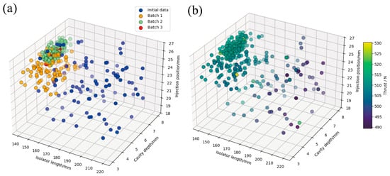
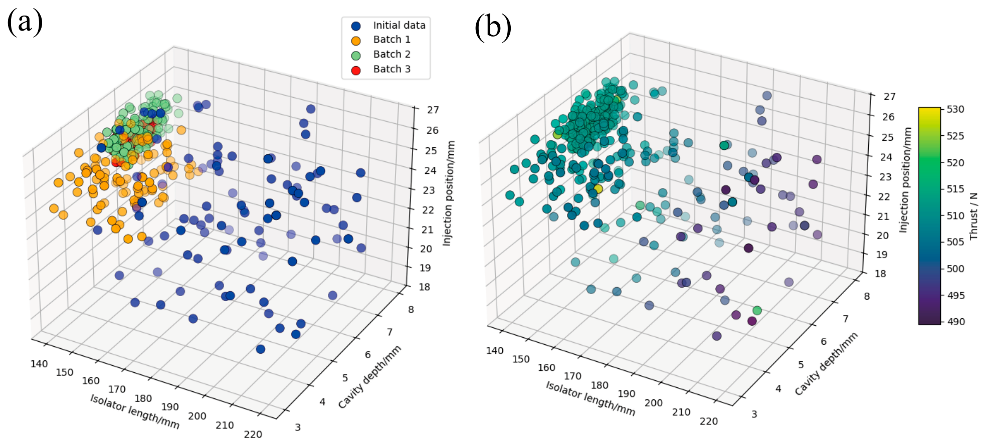
First, the Optimizer performs Latin Hypercube Sampling (LHS) of the design variables within the initial design space. The Interactor receives the user’s requirements and, assisted by the RAG library, generates case files and encodes the input parameters required by the solver into the input json file. The Runner conducts pre-processing of the cases and submits them to the solver for computation, after which the Corrector removes anomalous cases and records the causes of failure. After completing the first batch of 100 case calculations, the Optimizer evaluates the thrust values of the obtained configurations, shrinks the design space based on the response surface model, and determines the sampling range for the next batch of design variables by adapting the RSM method. After three rounds of iterative optimization, the optimal configuration is ultimately identified. The progress is shown in Figure 9.
Figure 9.
Schematic of Sampling and Calculation Data. (a) Design Space Shrinking Process; (b) Thrust Value of Configurations.
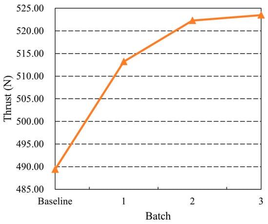
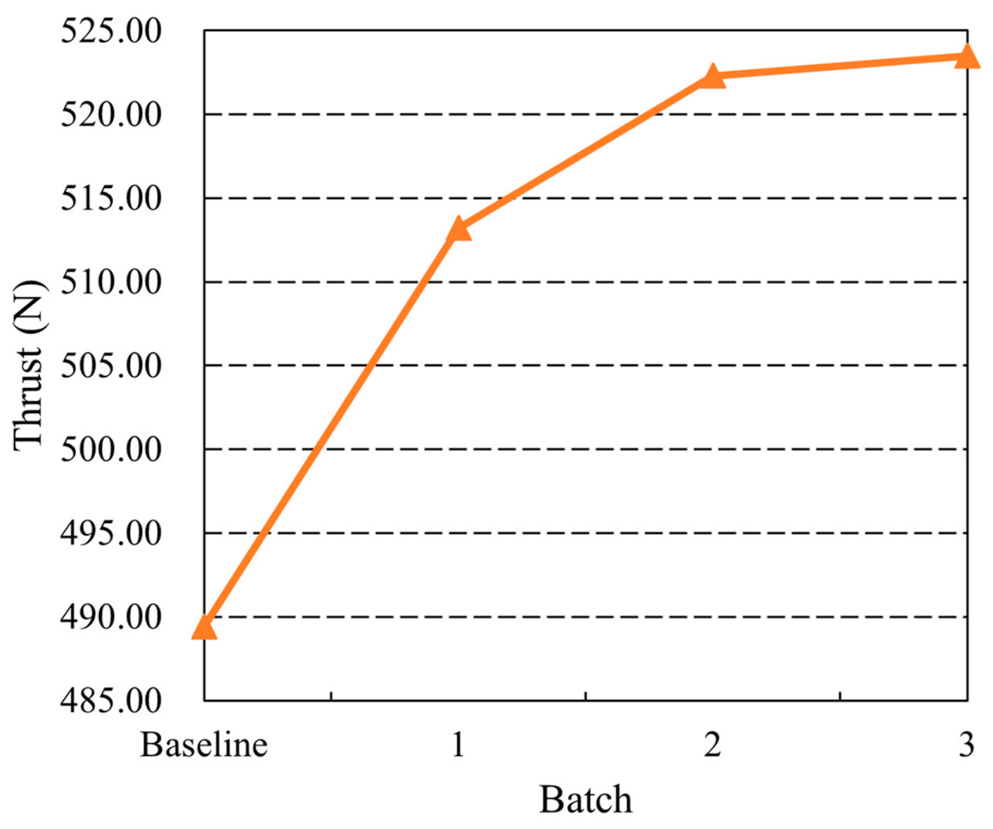
As shown in Figure 10, when the optimization proceeded to the third iteration, the improvement in thrust became negligible. Accordingly, the optimizer can be considered to have found the optimal configuration within the current design space. The thrust of the baseline configuration is 489.4 N. After three rounds of optimization iterations, the maximum thrust of the new configuration reaches 523.5 N, with mm, mm and mm, achieving a thrust increment of 6.97%.
Figure 10.
Maximum Thrust of Baseline Configuration and All Optimization Batches.
4. Conclusions
Scramjet combustor configuration optimization suffers from excessive manual intervention, high professional barriers, and the prohibitive cost of traditional numerical methods. This paper presents G-Agent, an LLM-driven multi-agent framework that automates the entire optimization workflow.
G-Agent consists of four specialized agents. The interactor initiates a natural dialog, clarifies user requirements, and generates formatted solver input files. The runner manages mesh generation, solver configuration, and numerical simulation execution. The corrector diagnoses failed cases by analyzing fault logs and applies corrective actions. The optimizer coordinates the entire process, shrinking the design space iteratively via a trust-region response surface method. A Retrieval-Augmented Generation (RAG) module injects domain-specific expert rules and continuously accumulates historical failure cases. This substantially enhances the reliability of the lightweight, locally deployed LLM.
Applied to an axisymmetric cavity-based scramjet combustor, G-Agent optimized the isolator length, cavity depth, and fuel injector position to maximize thrust. Starting from a baseline thrust of 489.4 N, the framework attained an optimized thrust of 523.5 N after three iterations, achieving a 6.97% improvement. The entire closed-loop process was completed without manual intervention beyond the initial specification, which covers requirement analysis, parameter generation, mesh generation, simulation execution, and optimization decision-making.
These results demonstrate that G-Agent significantly lowers the technical skill threshold and manual workload in scramjet combustor design. The framework establishes a practical pathway for integrating LLMs with domain-specific engineering solvers. Nevertheless, the locally deployed Qwen3-VL-2B-Instruct model is limited in reasoning capability and context length due to its modest parameter scale. Future work will investigate scaling the model size, enriching the knowledge base, and extending the framework to complex geometries and multi-objective optimization tasks.
Author Contributions
Conceptualization, Y.F. and D.X.; Methodology, D.X.; Software, G.Z.; Investigation, Y.F. and D.X.; Resources, G.Z., Y.Y. and M.S.; Data curation, Y.F.; Writing—original draft, Y.F.; Writing—review & editing, D.X.; Visualization, Y.F.; Supervision, D.X., G.Z., Y.Y. and H.W.; Project administration, Y.Y. and H.W.; Funding acquisition, H.W. and M.S. All authors have read and agreed to the published version of the manuscript.
Funding
This research was funded by Young Scientists Fund (Category A) of the National Natural Science Foundation of China grant number 12525202 and the APC was covered by this fund.
Data Availability Statement
The data presented in this study are available on request from the corresponding author due to our simulation data are generated by self-developed the inhouse code.
Conflicts of Interest
The authors declare no conflict of interest.
References
- Yu, W.; Hu, Y.; Zhao, S.; Wang, R. Progress and Development of Solid-Fuel Scramjet Technologies. Aerospace 2025, 12, 351. [Google Scholar] [CrossRef] [Scilit]
- Liu, X.; Shi, Y.; Yang, Q.; Yang, H.; Du, X.; Wang, X. Adaptive reverse Monte Carlo method and evaluation for infrared radiation characteristics of scramjet. Chin. J. Aeronaut. 2025, 38, 103524. [Google Scholar] [CrossRef] [Scilit]
- Madhumitha, R.; Karmakar, S. Boron-loaded gel fuel as potential fuel for ramjet and scramjet engines- recent advancements. FirePhysChem 2024, 4, 185–200. [Google Scholar] [CrossRef] [Scilit]
- Song, X.; Cai, Z.; Ji, J.; Chen, Z.; Wang, T.; Li, F.; Sun, M. Feasibility study of hydrogen-ammonia synergistic combustion in scramjets across broad Mach ranges. Nat. Commun. 2025, 16, 11312. [Google Scholar] [CrossRef] [Scilit]
- Tian, Y.; Zhu, J.; Sun, M.; Wang, H.; Huang, Y.; Feng, R.; Yan, B.; Sun, Y.; Cai, Z. Enhancement of blowout limit in a Mach 2.92 cavity-based scramjet combustor by a gliding arc discharge. Proc. Combust. Inst. 2023, 39, 5697–5705. [Google Scholar] [CrossRef] [Scilit]
- Ogawa, S.; Kobayashi, K.; Tomioka, S. Forced ignition modeling of methane-ethylene mixtures in scramjet combustors. Combust. Flame 2024, 263, 113383. [Google Scholar] [CrossRef] [Scilit]
- Miao, H.; Zhang, Z.; Zheng, X.; Li, J.; Wu, Y.; Li, Y. Investigation on impact of spark single-pulse energy storage on ignition performance in a scramjet combustor. Appl. Therm. Eng. 2025, 265, 125586. [Google Scholar] [CrossRef] [Scilit]
- Pugazhendhi, A.; Kamarudin, S.; Praveenkumar, T.; Sekar, M. Asymmetric injection and cross-flow effects on mixing and combustion in a hydrogen powered DLR scramjet propulsion system. Int. J. Hydrogen Energy 2025, 143, 679–690. [Google Scholar] [CrossRef] [Scilit]
- Fu, Y.; Li, J.; Song, W.; Wu, P.; Wang, Q.; Luo, Y. Effect of fuel distribution strategies on combustion performance in a core burning scramjet combustor. Phys. Fluids 2025, 37, 077167. [Google Scholar] [CrossRef] [Scilit]
- Wu, G.; Yu, X.; Peng, J.; Yang, C.; Cao, Z.; Qin, F.; Zhu, S.; Yuan, X.; Zhang, S.; Chen, X. Experimental investigation on the mixing and combustion characteristics with dual combined flame stabilizers in scramjet using simultaneous OH/kerosene-PLIF and Mie scattering measurements. Appl. Therm. Eng. 2025, 277, 127004. [Google Scholar] [CrossRef] [Scilit]
- Zhang, J.; Dou, S.; Wang, X.; Li, M.; Yang, Q.; Xu, X. Investigation on combustor performance of a ramp-based solid rocket scramjet with ethylene addition. Acta Astronaut. 2025, 234, 131–140. [Google Scholar] [CrossRef] [Scilit]
- Venkateswarlu, K.; Reddy, S.V.K. The Influence of Strut Injection Methods on Flame Stabilization and Combustion Performance of Scramjet Engines: A Review. Int. J. Aeronaut. Space Sci. 2025, 26, 2345–2370. [Google Scholar] [CrossRef] [Scilit]
- Sgubin, L.G.; Ribeiro, L.A.G.; Silva, M.T.A.; Minucci, M.A.S.; Galembeck, L.; Rêgo, I.d.S. Assessment of heat flux on a printed scramjet inlet at Mach 7 with coaxial thermocouples in a reflected shock tunnel. Aerosp. Sci. Technol. 2025, 158, 109890. [Google Scholar] [CrossRef] [Scilit]
- Liu, H.; Chen, Y.; Huang, Y.; Song, T.; Shen, W.; Tian, Y.; You, Y. Clustering investigation of scramjet combustion processes based on contrastive learning. Acta Astronaut. 2025, 233, 55–65. [Google Scholar] [CrossRef] [Scilit]
- Kim, G.; Shim, H.; Jung, S.; Park, G.; Choi, H.; Jeon, G. Experimental performance evaluation of a single-body typed TDLAS sensor using a scramjet ground test facility. Exp. Fluids 2025, 66, 190. [Google Scholar] [CrossRef] [Scilit]
- Zhou, W.; Cao, Z.; Dou, S.; Yang, Q.; Xu, L. Simultaneous Mach number, thrust, and combustion efficiency measurement for a scramjet by using a beam-jitter-resistant TDLAS sensor. Measurement 2025, 256, 118169. [Google Scholar] [CrossRef] [Scilit]
- Jeong, B.; Kim, K.; Park, G. Three-component force measurement system of scramjet model in a shock tunnel. J. Mech. Sci. Technol. 2025, 39, 287–302. [Google Scholar] [CrossRef] [Scilit]
- Tang, T.; Wang, Z.; Yu, J.; Huang, Y.; Sun, M.; Wang, H.; Zhao, G.; Yang, Y.; Xiong, D. Investigation of multi-scale flow structures and combustion characteristics in a cavity-enhanced circular scramjet. Combust. Flame 2024, 264, 113431. [Google Scholar] [CrossRef] [Scilit]
- Jeyakumar, S.; Muthu, G.S.M. Numerical Investigations on the Influence of Ramp Locations in a Strut Injection Scramjet Combustor. Int. J. Aeronaut. Space Sci. 2025, 26, 1676–1691. [Google Scholar] [CrossRef] [Scilit]
- Ma, G.; Zhao, G.; Sun, M.; Tang, T.; Li, F.; Xiong, D. Role of cavity in a Mach 8 axisymmetric scramjet combustor: Flame stabilization vs combustion enhancement. Phys. Fluids 2024, 36, 015118. [Google Scholar] [CrossRef] [Scilit]
- Venkateshwaran, V.; Jeyakumar, S.; Desai, H.A.K.; Gupta, S.; Kumar, R.G.; Satheesh, A.; Padmanathan, P. The impact of diamond struts and strategic injector placement for flame holding and enhanced combustion efficiency in scramjet combustor. Int. J. Hydrogen Energy 2025, 174, 151335. [Google Scholar] [CrossRef] [Scilit]
- Deng, X.; Tian, Y.; Chen, E.; Yang, M.; Zhang, H.; Le, J. Research on intelligent prediction method of supersonic flow field in scramjet based on deep learning: A review. Expert Syst. Appl. 2025, 279, 127500. [Google Scholar] [CrossRef] [Scilit]
- Brunton, S.L.; Noack, B.R.; Koumoutsakos, P. Machine Learning for Fluid Mechanics. Annu. Rev. Fluid Mech. 2020, 52, 477–508. [Google Scholar] [CrossRef] [Scilit]
- Duraisamy, K.; Iaccarino, G.; Xiao, H. Turbulence Modeling in the Age of Data. Annu. Rev. Fluid Mech. 2019, 51, 357–377. [Google Scholar] [CrossRef] [Scilit]
- Raiyan, A.R.; Hoque, M.A.; Hasan, M.J. Performance enhancement of a mixed compression scramjet intake through geometric modification using genetic algorithm optimization. Appl. Therm. Eng. 2025, 281, 128707. [Google Scholar] [CrossRef] [Scilit]
- Kong, C.; Chang, J.; Li, Y.; Wang, Z. A deep learning approach for the velocity field prediction in a scramjet isolator. Phys. Fluids 2021, 33, 026103. [Google Scholar] [CrossRef] [Scilit]
- An, J.; Wang, H.; Liu, B.; Luo, K.H.; Qin, F.; He, G.Q. A deep learning framework for hydrogen-fueled turbulent combustion simulation. Int. J. Hydrogen Energy 2020, 45, 17992–18000. [Google Scholar] [CrossRef] [Scilit]
- Tian, Y.; Zhao, Y.; Deng, X.; Yang, M.; Chen, E.; Xu, M.; Ren, H. An intelligent prediction method for supersonic flow field in scramjet isolator enhanced by feature details. Aerosp. Sci. Technol. 2025, 161, 110116. [Google Scholar] [CrossRef] [Scilit]
- Bao, Y.; Qiu, R.; Lou, J.; Han, X.; You, Y. Deep learning-based prediction of initiation jet momentum ratio in jet-induced oblique detonations. Aerosp. Sci. Technol. 2024, 155, 109724. [Google Scholar] [CrossRef] [Scilit]
- Chen, H.; Tian, Y.; Guo, M.; Le, J.; Ji, Y.; Zhang, Y.; Zhang, H.; Zhang, C. Flow field reconstruction and shock train leading edge position detection of scramjet isolation section based on a small amount of CFD data. Adv. Aerodyn. 2022, 4, 28. [Google Scholar] [CrossRef] [Scilit]
- Kong, C.; Wang, Z.; Zhang, J.; Wang, X.; Wang, K.; Li, Y.; Chang, J. Research on flame prediction in a scramjet combustor using a data-driven model. Phys. Fluids 2022, 34, 066101. [Google Scholar] [CrossRef] [Scilit]
- Guo, M.; Chen, H.; Tian, Y.; Wu, D.; Deng, X.; Le, J.; Zhang, H.; Zhong, F. Research on time series prediction of the flow field in supersonic combustor based on deep learning. Aerosp. Sci. Technol. 2023, 140, 108459. [Google Scholar] [CrossRef] [Scilit]
- Chen, E.; Guo, M.; Deng, J.; Tian, Y.; Deng, X.; Le, J.; Zhang, H. Supersonic combustion field evolution prediction in scramjet engine using a deblurring multi-scale attention network. Expert Syst. Appl. 2024, 252, 124290. [Google Scholar] [CrossRef] [Scilit]
- Huang, S.; Tian, Y.; Deng, X.; Yang, M.; Chen, E.; Zhang, H. Supersonic combustion flow field reconstruction in a scramjet based on deep learning method. Aerosp. Sci. Technol. 2025, 161, 110169. [Google Scholar] [CrossRef] [Scilit]
- Guan, Q.; Dong, X.; Zhang, W.; Sun, L.; Zhu, J.; Luo, T.; Xu, S. Mode recognition in a kerosene-fueled scramjet combustor by a Swin Transformer neural network. Phys. Fluids 2025, 37, 025101. [Google Scholar] [CrossRef] [Scilit]
- Xu, W.; Yang, T.; Liu, C.; Wu, K.; Zhang, P. Stabilization analysis and mode recognition of kerosene supersonic Combustion: A deep learning approach based on Res-CNN-β-VAE. Proc. Combust. Inst. 2025, 41, 105976. [Google Scholar] [CrossRef] [Scilit]
- Miah, S.U.; Kabir, M.; Sarwar, T.B.; Safran, M.; Alfarhood, S.; Mridha, M.F. A multimodal approach to cross-lingual sentiment analysis with ensemble of transformer and LLM. Sci. Rep. 2024, 14, 9603. [Google Scholar] [CrossRef] [Scilit]
- Birhane, A.; Kasirzadeh, A.; Leslie, D.; Wachter, S. Science in the age of large language models. Nat. Rev. Phys. 2023, 5, 277–280. [Google Scholar] [CrossRef] [Scilit]
- Liu, R.; Li, C.; Tang, H.; Ge, Y.; Shan, Y.; Li, G. ST-LLM: Large Language Models Are Effective Temporal Learners. In Proceedings of the Computer Vision—ECCV, Milan, Italy, 29 September–4 October 2024; pp. 1–18. [Google Scholar]
- Ramos, M.C.; Collison, C.J.; White, A.D. A review of large language models and autonomous agents in chemistry. Chem. Sci. 2025, 16, 2514–2572. [Google Scholar] [CrossRef] [Scilit]
- Jablonka, K.M.; Schwaller, P.; Ortega-Guerrero, A.; Smit, B. Leveraging large language models for predictive chemistry. Nat. Mach. Intell. 2024, 6, 161–169. [Google Scholar] [CrossRef] [Scilit]
- Shool, S.; Adimi, S.; Amleshi, R.S.; Bitaraf, E.; Golpira, R.; Tara, M. A systematic review of large language model (LLM) evaluations in clinical medicine. BMC Med. Inform. Decis. Mak. 2025, 25, 117. [Google Scholar] [CrossRef] [Scilit]
- Kim, J.K.; Chua, M.; Rickard, M.; Lorenzo, A. ChatGPT and large language model (LLM) chatbots: The current state of acceptability and a proposal for guidelines on utilization in academic medicine. J. Pediatr. Urol. 2023, 19, 598–604. [Google Scholar] [CrossRef] [Scilit]
- Gallifant, J.; Afshar, M.; Ameen, S.; Aphinyanaphongs, Y.; Chen, S.; Cacciamani, G.; Demner-Fushman, D.; Dligach, D.; Daneshjou, R.; Fernandes, C.; et al. The TRIPOD-LLM reporting guideline for studies using large language models. Nat. Med. 2025, 31, 60–69. [Google Scholar] [CrossRef] [Scilit]
- Jiang, G.; Ma, Z.; Zhang, L.; Chen, J. EPlus-LLM: A large language model-based computing platform for automated building energy modeling. Appl. Energy 2024, 367, 123431. [Google Scholar] [CrossRef] [Scilit]
- Kalyuzhnaya, A.; Mityagin, S.; Lutsenko, E.; Getmanov, A.; Aksenkin, Y.; Fatkhiev, K.; Fedorin, K.; Nikitin, N.O.; Chichkova, N.; Vorona, V.; et al. LLM Agents for Smart City Management: Enhancing Decision Support Through Multi-Agent AI Systems. Smart Cities 2025, 8, 19. [Google Scholar] [CrossRef] [Scilit]
- Lin, L.; Zhang, S.; Fu, S.; Liu, Y. FD-LLM: Large language model for fault diagnosis of complex equipment. Adv. Eng. Inform. 2025, 65, 103208. [Google Scholar] [CrossRef] [Scilit]
- Farquhar, S.; Kossen, J.; Kuhn, L.; Gal, Y. Detecting hallucinations in large language models using semantic entropy. Nature 2024, 630, 625–630. [Google Scholar] [CrossRef] [Scilit]
- Wang, G.; Cheng, S. Can foundation language models predict fluid dynamics? Eng. Appl. Artif. Intell. 2025, 158, 111427. [Google Scholar] [CrossRef] [Scilit]
- Zhang, X.; Xu, Z.; Zhu, G.; Tay, C.M.J.; Cui, Y.; Khoo, B.C.; Zhu, L. Using large language models for parametric shape optimization. Phys. Fluids 2025, 37, 083601. [Google Scholar] [CrossRef] [Scilit]
- Zhang, Y.; Zheng, K.; Liu, F.; Zhang, Q.; Wang, Z. AutoTurb: Using large language models for automatic algebraic turbulence model discovery. Phys. Fluids 2025, 37, 015211. [Google Scholar] [CrossRef] [Scilit]
- Pandey, S.; Xu, R.; Wang, W.; Chu, X. OpenFOAMGPT: A retrieval-augmented large language model (LLM) agent for OpenFOAM-based computational fluid dynamics. Phys. Fluids 2025, 37, 035120. [Google Scholar] [CrossRef] [Scilit]
- Wang, W.; Xu, R.; Feng, J.; Zhang, Q.; Pandey, S.; Chu, X. A status quo investigation of large-language models for cost-effective computational fluid dynamics automation with OpenFOAMGPT. Theor. Appl. Mech. Lett. 2025, 15, 100623. [Google Scholar] [CrossRef] [Scilit]
- Dong, Z.; Lu, Z.; Yang, Y. Fine-tuning a large language model for automating computational fluid dynamics simulations. Theor. Appl. Mech. Lett. 2025, 15, 100594. [Google Scholar] [CrossRef] [Scilit]
- Xu, Z.; Wang, L.; Wang, C.; Chen, Y.; Luo, Q.; Yao, H.-D.; Wang, S.; He, G. CFDAgent: A language-guided, zero-shot multi-agent system for complex flow simulation. Phys. Fluids 2025, 37, 117124. [Google Scholar] [CrossRef] [Scilit]
- Wang, L.; Zhang, L.; He, G. Evaluations of large language models in computational fluid dynamics: Leveraging, learning and creating knowledge. Theor. Appl. Mech. Lett. 2025, 15, 100597. [Google Scholar] [CrossRef] [Scilit]
- Liu, M.; Sun, M.; Zhao, G.; Meng, Y.; Huang, Y.; Ma, G.; Wang, H. Effect of combustion mode on thrust performance in a symmetrical tandem-cavity scramjet combustor. Aerosp. Sci. Technol. 2022, 130, 107904. [Google Scholar] [CrossRef] [Scilit]
- Ma, G.; Sun, M.; Zhao, G.; Liang, C.; Wang, H.; Yu, J. Effect of injection scheme on asymmetric phenomenon in rectangular and circular scramjets. Chin. J. Aeronaut. 2023, 36, 216–230. [Google Scholar] [CrossRef] [Scilit]
- Tang, T.; Wang, Z.; Yu, J.; Huang, Y.; Sun, M.; Wang, H.; Zhao, G.; Yang, Y.; Xiong, D. Numerical study of transverse jet mixing and combustion in a high-enthalpy supersonic crossflow with trace gases. Phys. Fluids 2023, 35, 036120. [Google Scholar] [CrossRef] [Scilit]
- Lewis, P.; Perez, E.; Piktus, A.; Petroni, F.; Karpukhin, V.; Goyal, N.; Küttler, H.; Lewis, I.; Yih, W.; Rocktäschel, T.; et al. Retrieval-augmented generation for knowledge-intensive NLP tasks. arXiv 2020, arXiv:2005.11401. [Google Scholar]
- Fatima, S.K.; Arshad, S.; Hassan, M.A.; Iqbal, F.; Altaf, A.; Aziz, I.; Ashraf, I.; Samee, N.A. Context-aware chatbot for personal healthcare assistance using LLMs and LangChain. J. Intell. Inf. Syst. 2025, 63, 1921–1953. [Google Scholar] [CrossRef] [Scilit]
- Morales-Chan, M.; Amado-Salvatierra, H.R.; Medina, J.A.; Barchino, R.; Hernández-Rizzardini, R.; Teixeira, A.M. Personalized Feedback in Massive Open Online Courses: Harnessing the Power of LangChain and OpenAI API. Electronics 2024, 13, 1960. [Google Scholar] [CrossRef] [Scilit]
- Xiong, D.; Sun, M.; Yu, J.; Hu, Z.; Yang, Y.; Wang, H.; Wang, Z. Effects of confinement and curvature on a jet in a supersonic cross-flow. Proc. Inst. Mech. Eng. Part G J. Aerosp. Eng. 2022, 236, 3518–3530. [Google Scholar] [CrossRef] [Scilit]
- Lai, J.; Yu, H.; Tian, Z.; Li, H. Hybrid MPI and CUDA Parallelization for CFD Applications on Multi-GPU HPC Clusters. Sci. Program. 2020, 2020, 8862123. [Google Scholar] [CrossRef] [Scilit]
- Menter, F.R. Two-equation eddy-viscosity turbulence models for engineering applications. AIAA J. 1994, 32, 1598–1605. [Google Scholar] [CrossRef] [Scilit] [PubMed]
- Huang, W.; Tan, J.-G.; Liu, J.; Yan, L. Mixing augmentation induced by the interaction between the oblique shock wave and a sonic hydrogen jet in supersonic flows. Acta Astronaut. 2015, 117, 142–152. [Google Scholar] [CrossRef] [Scilit]
- Liu, Q.; Baccarella, D.; McGann, B.; Lee, T. Cavity-Enhanced Combustion Stability in an Axisymmetric Scramjet Model. AIAA J. 2019, 57, 3898–3909. [Google Scholar] [CrossRef] [Scilit]
- Ma, G.; Sun, M.; Zhao, G.; Liu, P.; Tang, T.; Fan, L.; Wang, H. Numerical Investigation of an Axisymmetric Model Scramjet Assisted with Cavity of Different Aft Wall Angles. Int. J. Aerosp. Eng. 2021, 2021, 7525824. [Google Scholar] [CrossRef] [Scilit]



Disclaimer/Publisher’s Note: The statements, opinions and data contained in all publications are solely those of the individual author(s) and contributor(s) and not of MDPI and/or the editor(s). MDPI and/or the editor(s) disclaim responsibility for any injury to people or property resulting from any ideas, methods, instructions or products referred to in the content. |
© 2026 by the authors. Licensee MDPI, Basel, Switzerland. This article is an open access article distributed under the terms and conditions of the Creative Commons Attribution (CC BY) license.