


Abstract
Directional asymmetry and Dutch-roll are critical phenomena observed during powered parafoil vehicle (PPV) flight tests, complicating stable flight and leading to obvious lateral–directional biases in autopilot tracking. However, existing PPV models typically neglect propeller counter-torque (PCT), resulting in limited research on directional asymmetry. Moreover, conventional Newton–Euler formulations require explicit treatment of internal constraint forces, complicating analytical linearization and local stability analysis. To address these issues, first, this paper develops a nonlinear 9-degree-of-freedom (9-DOF) PPV model using Kane’s equations with quasi-velocities. This multibody dynamic model provides a compact and structurally consistent basis for linearization and stability analysis. Subsequently, the mechanism analysis shows that PCT shifts the coupled roll–yaw equilibrium and is the primary physical source of the observed directional asymmetry. In addition, the Dutch-roll mode is identified as the dominant oscillatory mode governing the lateral–directional stability of the PPV. The modal analysis further indicates that increasing thrust and directional control inputs reduce the Dutch-roll damping ratio. On this basis, a damping-ratio-based flight envelope is constructed. Furthermore, numerical simulations and flight-test comparisons demonstrate that the proposed model captures the principal PPV dynamic responses. The simulation results also support the mechanism analysis of directional asymmetry and the Dutch-roll.
1. Introduction
A powered parafoil vehicle (PPV) consists of a parafoil connected to a rigid payload through risers. It combines a high lift-to-drag ratio, packable wings, and a favorable payload-to-weight ratio, enabling applications in reconnaissance, precision airdrop, fog abatement, and rocket-booster recovery [1,2,3,4]. While the flexible flight structure brings excellent flight characteristics, the homing of the parafoil will be seriously disturbed by wind disturbance [5], which results in the low trajectory control accuracy and significant landing error [6]. The longitudinal (thrust) channel and the directional channel (differential deflection of the trailing-edge brakes) are strongly coupled [7,8].
Existing studies on parafoil systems dynamics have progressively evolved from low-order rigid-body representations to coupled multibody formulations. Early 3–6 DOF models were mainly used to investigate level turns, climbs, and wind-affected trajectories [9,10]. Subsequent studies introduced relative canopy–payload rotational motions, leading to 7–9 DOF models capable of reproducing the coupled motion of the canopy and payload [11,12,13,14,15,16]. Among them, the spring–damper moment has been used to describe canopy–payload coupling, and experimental investigations have provided further support for the multibody formulations [12,13,14]. In parallel, different modeling methodologies for parafoil systems have been adopted for PPV dynamics. Newton–Euler formulations have been widely used for turning, gliding, and controller design [17,18]. A known limitation of Newton–Euler formulations is that internal forces are explicitly present, which complicates analysis. To avoid the explicit treatment of internal forces, Sun [1,19,20] adopted a Lagrange modeling method for parafoil control studies without explicitly retaining internal forces in the governing equations. Hamiltonian and quasi-Hamiltonian formulations have also been introduced for coupled dynamic and stability analyses [21,22]. More recently, active-modeling [23] and data-driven representations, including neural-network and linear-parameter-varying models, have been investigated to compensate for modeling uncertainty or reduce computational complexity [24,25,26,27,28].
In addition to modeling methods, several studies have investigated the system parameter effects on PPV dynamic characteristics. The influence of canopy area, rigging angle, and payload center-of-gravity (CG) offsets on longitudinal and lateral–directional dynamics have been examined through comparative simulations and parametric analyses [29,30,31,32,33,34]. In particular, Ochi showed that an internal rolling moment can drive coupled lateral–directional motion akin to that induced by asymmetric trailing-edge deflection, thereby altering turning response [34]. These studies demonstrate that PPV dynamic characteristics depend strongly on both vehicle configuration and canopy–payload coupling.
Beyond time-domain simulations, linearization-based approaches provide a useful basis for stability analysis and controller design. Existing studies have linearized 8-DOF parafoil models, approximately separated longitudinal and lateral–directional dynamics, and derived transfer-function representations for controller design [35,36]. Small-disturbance analyses have further shown that operating conditions and structural parameters, such as climb state, suspension length, and canopy dihedral, can significantly alter the system modes [37]. Eigenvalue analyses of high-glide parafoil systems have also identified Dutch-roll oscillatory behavior in the lateral–directional dynamics [38].
Overall, existing PPV modeling methods have been developed with various DOFs, and can reproduce the position and attitude of both the canopy and the payload [14]. Nevertheless, the dynamic analysis of such a nonlinear multibody aircraft remains insufficient because it is affected by canopy aerodynamics, payload dynamics, and canopy–payload coupling. Conventional modeling methods usually introduce internal constraint forces (Newton–Euler) or constrained formulations of multibody kinematics (Lagrange), which pose challenges for analytical linearization and the further modal analysis of PPV. As a result, the lateral modal characteristics of the 9-DOF model such as the Dutch-roll mode have not been systematically investigated. In addition, most existing PPV studies neglect PCT, making it difficult to reproduce the directional asymmetry observed in powered flight.
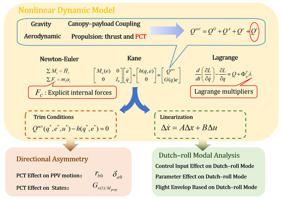
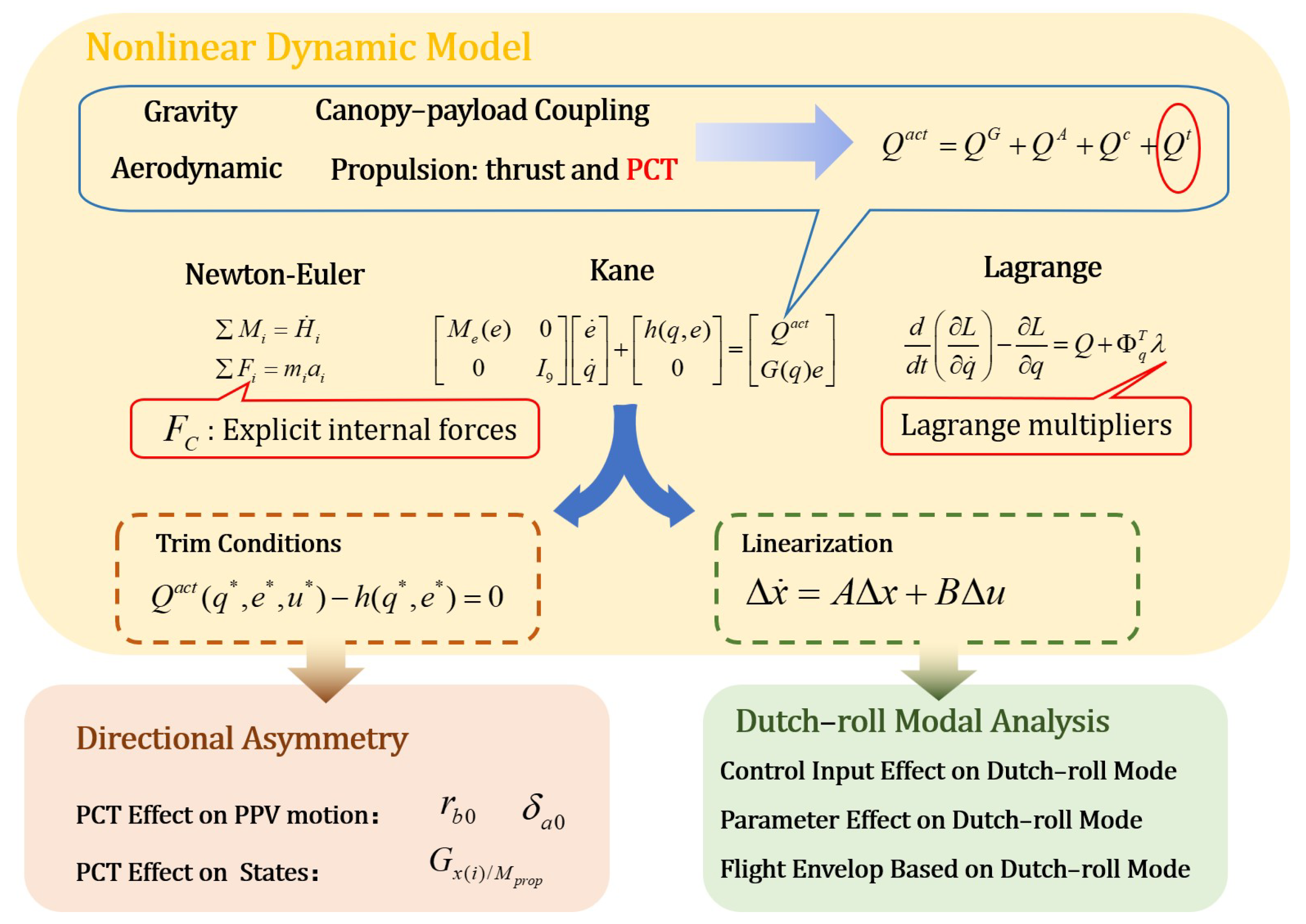
To address these issues, this paper develops a nonlinear multibody dynamic analysis framework for PPV using Kane’s equations. The proposed nonlinear model provides a structurally consistent basis for trim analysis, analytical linearization, and modal interpretation. Based on this framework, the mechanism of PCT-induced directional asymmetry is investigated, and the Dutch-roll characteristics under varying thrust and directional control inputs are analyzed. The main contributions of this paper are summarized as follows:
- (1)
- A Kane-based 9-DOF nonlinear multibody model with quasi-velocities is established for PPV. Distinct from conventional Newton–Euler [18] and Lagrange methods [20], the proposed model avoids the explicit inclusion of internal forces and constrained formulations of multibody kinematics. The resulting model provides a compact and structurally consistent basis for subsequent trim computation, analytical linearization, and stability analysis.
- (2)
- The mechanism of PCT-induced directional asymmetry is clarified. Compared with previous studies, this study incorporates PCT into the dynamic model, reproducing the phenomenon observed during flight tests. The trim and sensitivity analyses reveal that the roll-axis moment generated by PCT shifts the coupled roll–yaw equilibrium and produces asymmetric directional responses.
- (3)
- The Dutch-roll mode of the 9-DOF PPV lateral–directional dynamics is systematically analyzed. Unlike existing studies that mainly utilize comparative simulation to investigate the effects of system parameters on dynamic characteristics [31,32], this study conducts stability analysis of PPV through modal analysis under varying thrust and directional control inputs. Based on the constraint of Dutch-roll damping ratio, a flight envelope is constructed to characterize the admissible maneuver region for PPV flight.
- The overall framework of the proposed nonlinear multibody dynamic modeling and stability analysis is illustrated in Figure 1.Figure 1. Overall framework of the nonlinear multibody dynamic modeling and stability analysis for the PPV based on Kane’s equations.
The remainder of this paper is organized as follows. Section 2 presents the 9-DOF PPV dynamic model derived by Kane’s method, including the coordinate definition, external loads, coupling moments, trim formulation, and analytical linearization. Section 3 investigates the physical mechanism and quantitative characteristics of PCT-induced directional asymmetry. Section 4 analyzes the Dutch-roll mode of the lateral–directional dynamics and establishes a damping-ratio-based flight envelope. Section 5 validates the proposed framework through numerical simulations and flight-test comparisons. Finally, Section 6 concludes the paper.
2. Nonlinear Multibody Formulation of the PPV
2.1. System Description and Modeling Assumptions
Following previous parafoil system dynamic models [17,18], this study considers a powered parafoil vehicle comprising a flexible but inflated canopy and a rigid payload, connected by risers at a spherical hinge point C. The weight and thrust are concentrated in the payload, while aerodynamic forces and moments act mainly on the canopy. The canopy–payload internal constraint is represented as a spherical hinge with reaction forces and moments determined by the relative motion of the two bodies. The following standard assumptions are adopted:
- (1)
- When fully inflated, the canopy shape remains approximately fixed; flexible deformations not associated with commanded maneuvers are neglected;
- (2)
- The canopy center of pressure lies at 25% c from the leading edge;
- (3)
- Payload aerodynamics are neglected; the payload center of gravity (CG) lies in its symmetry plane;
- (4)
- Variations in the canopy inertia tensor and CG with attitude are neglected;
- (5)
- The canopy–payload connection is idealized as a spherical hinge at C, allowing free rotation of the canopy relative to the payload about all three axes.
These assumptions are consistent with established methodologies in PPV dynamic modeling [17,18,19] and enable a compact 9-DOF representation capturing the principal coupled rigid-body dynamics while avoiding Lagrange multipliers. Although canopy deformation may affect the actual mass distribution, such effects are not considered in the present model since this study focuses on normal flight conditions.
2.2. Kinematics, Generalized Coordinates and Quasi-Velocities
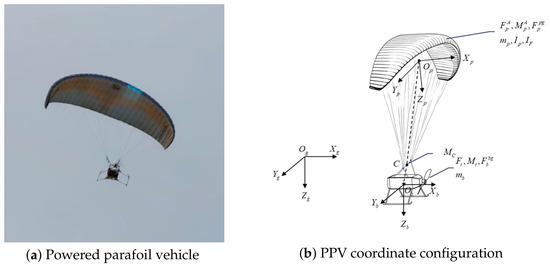
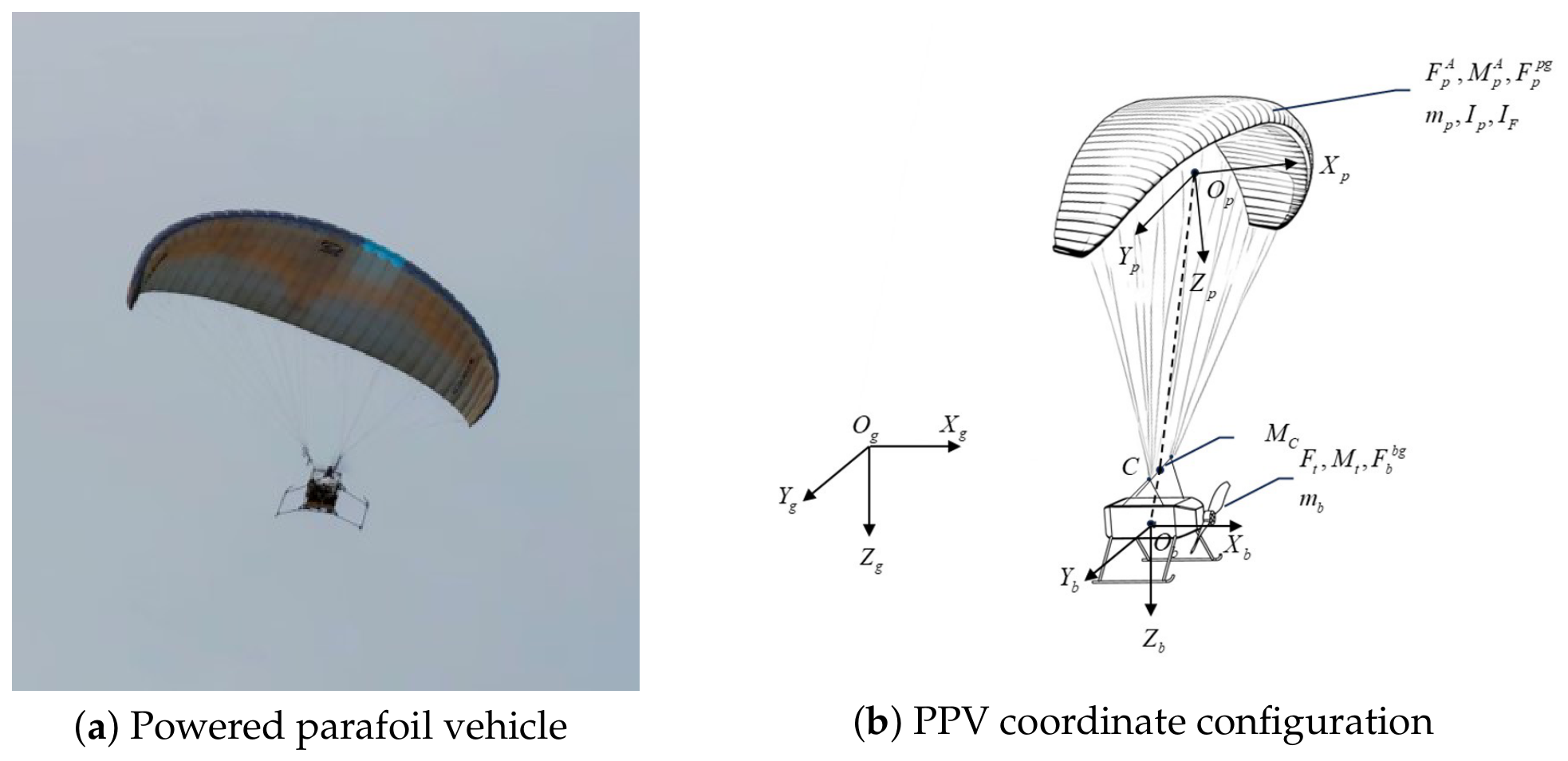
Three right-handed frames are illustrated in (Figure 2):
Figure 2.
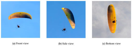
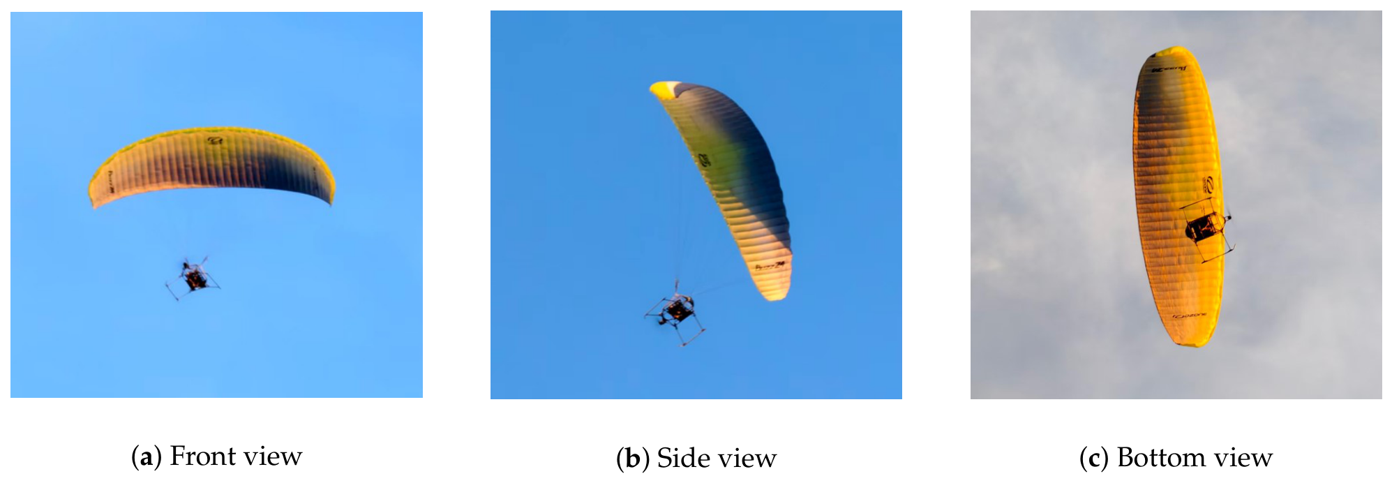
PPV and coordinate configuration. (a) shows the PPV during the flight test, and (b) illustrates the geodetic frame, payload body frame, canopy body frame.
- (1)
- Geodetic frame : (NED);
- (2)
- Canopy body frame : with at the canopy mass center; points toward the riser junction C; points to the right wing; completes a right-handed triad;
- (3)
- Payload body frame : with at the payload geometric center; aligned with the thrust axis; lies in the payload symmetry plane and is orthogonal to ; is determined by the right-hand rule.
The attitudes are described by Z–Y–X Euler angles for the payload and for the canopy. The onboard IMU directly measures the payload Euler angles. Let be the direction-cosine matrix (DCM) from to , and the inertial-to-canopy DCM is . Then, the DCM from the payload to the canopy is . These matrices are used for all vector/frame transformations in what follows.
To avoid the explicit appearance of constraint forces, the system is parameterized in terms of the kinematics of the spherical hinge point C:
where are the components of the hinge point C position in , and , are Z–Y–X Euler angles of the payload and canopy, respectively.
The corresponding quasi-velocities are chosen as follows:
where are the components of the translational velocity of the hinge point C in , and , are the body-axis angular-rate triplets of the payload and canopy, i.e., in and in .
The kinematic relations between the generalized-coordinate rates and the quasi-velocities are established as follows:
- (1)
- The translational coordinate rates of the spherical hinge point C in are related to its body-axis velocity components:
- (2)
- The Euler-angle rates of the payload and canopy are expressed in terms of their respective body angular velocities:with
- (3)
- These relations are assembled into a transformation matrix linking the generalized-coordinate rates to the quasi-velocities:
- (4)
- The body-axis velocity components of the payload and canopy are written as functions of the selected quasi-velocity vector:where S represents the skew-symmetric cross-product operator, e.g., .
2.3. Forces and Moments
In the proposed PPV dynamic model, the external loads consist of gravity, canopy aerodynamic forces and moments, thrust, propeller counter-torque, and the back turn moment.
2.3.1. Gravity
Gravity acts on the centers of mass of the payload and canopy. Let , be the masses and g the inertial gravitational acceleration. The corresponding gravitational forces are in and in . The generalized forces are obtained by projecting these forces and their moments onto the partial velocities associated with each quasi-velocity.
2.3.2. Aerodynamics of the Canopy
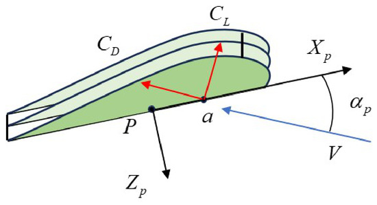
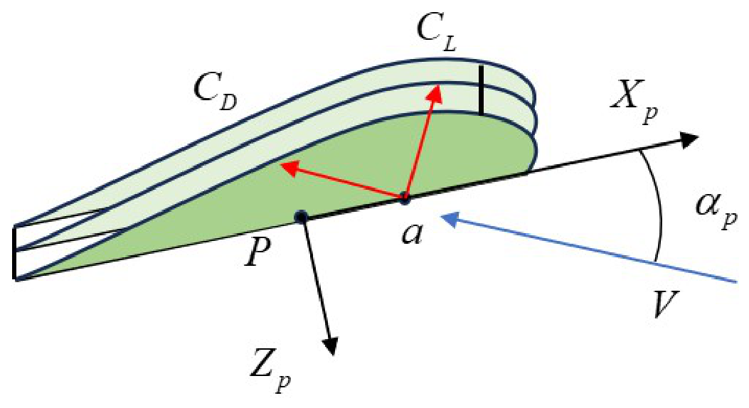
Define the canopy relative wind at its aerodynamic reference point a (Figure 3):
Figure 3.
Definition of angle of attack.
The angle of attack and sideslip angle are defined in as follows:
Two control deflections are considered:
: the symmetric trailing-edge deflection (both sides), primarily affecting longitudinal coefficients , and : the asymmetric trailing-edge deflection (left–right differential), mainly affecting lateral–directional coefficients .
The aerodynamic force and moment in are expressed as follows:
where is the dynamic pressure. Following the aerodynamic coefficient formulation in [17], the aerodynamic coefficients are expressed as functions of the instantaneous angle of attack, sideslip angle, angular rates, and trailing-edge deflections. Accordingly, the longitudinal aerodynamic coefficients and lateral–directional coefficients are represented by the following:
- (1)
- Longitudinal coefficients : the canopy exhibits strong nonlinear dependence on and . For use in dynamics, we approximate the longitudinal coefficients by a low-order polynomial.
- (2)
- Lateral–directional coefficients : the lateral–directional behavior is mainly influenced by sideslip and asymmetric control , with higher-order couplings.
The low-order aerodynamic representation is established for the normal flight regime of the PPV. When the vehicle operates at large angles of attack or with large control deflections, aerodynamic nonlinearities induced by canopy deformation and flow separation may become significant, which are not considered in the present model.
2.3.3. Thrust and Propeller Counter-Torque
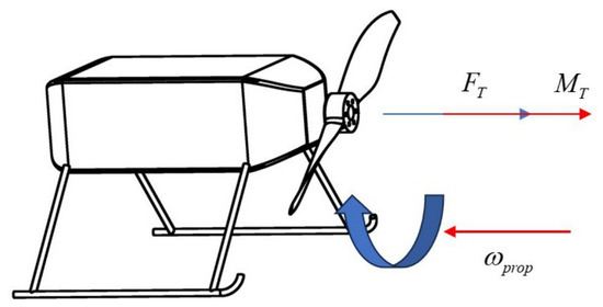
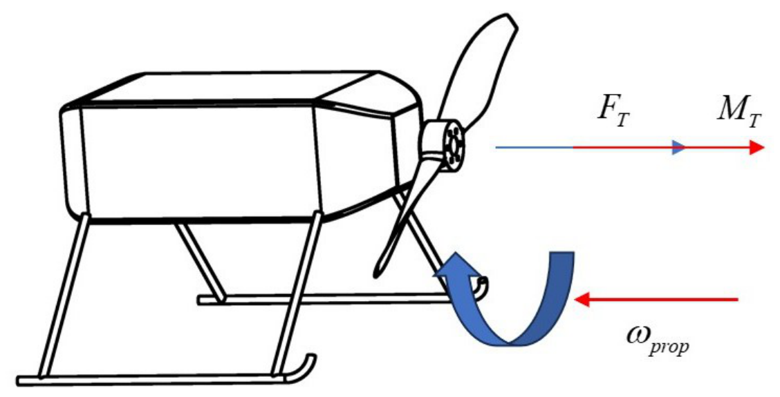
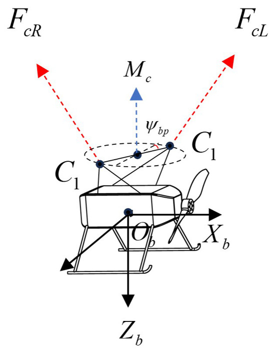
The propulsion system consists of a motor–propeller unit that generates thrust along the -axis. In addition, the aerodynamic reaction on the rotating propeller produces a counter-torque about the , as shown in Figure 4.
Figure 4.
Thrust and propeller counter-torque of the propulsion system.
Motivated by the observed directional asymmetry, we explicitly incorporate PCT into the model to refine the dynamic equations, enabling a high-fidelity representation of powered turning flight.
2.3.4. Canopy–Payload Coupling and Back Turn Moment
In the adopted 9-DOF dynamic model, the canopy–payload coupling is explicitly modeled at the hinge point C. Interestingly, in Tan’s study, the canopy–payload coupling is represented explicitly by the two riser force vectors [16]. However, for dynamic modeling, the so-called “back turn” moment representation has been widely adopted [12]. Furthermore, building on the canopy–payload relative motion, Muller derived a closed-form expression for this rotational moment [39]. Following Muller’s approach, this subsection details the geometric configuration, symmetric load transfer, and asymmetric effects that generate the back turn moment.
- (1)
- Geometry and basic assumptionsThe canopy is connected to the payload through a set of risers. For modeling, two effective attachment points are introduced on the payload and two corresponding points on the canopy:
- On the payload (body frame )left/right anchor positionsmeasured from point b to anchor point , and expressed in .
- On the canopy (body frame ):Assuming that the canopy resultant action on the payload aligns with the riser direction, which is fixed in the canopy frame by the angle between the riser and :
The geometric configuration and force transmission associated with the back turn moment are illustrated in Figure 5.Figure 5. Back turn moment of canopy–payload coupling. and represent the force generated by the risers. - (2)
- inThe resultant force of and can be expressed in as follows:In steady flight, , which means that the magnitudes of the internal forces on both sides are similar:
- (3)
- Back turn moment inAssuming that the suspension points and remain fixed in the and are arranged symmetrically on both sides of the longitudinal symmetry plane, the moment generated at the payload attachment point by the forces and is given byAfter expansion and simplification, this can be written as follows:Furthermore, to account for the relative rotational damping between the canopy and payload caused by the flexible attachment and suspension system, an equivalent damping term is introduced following previous parafoil–payload dynamic models [12,34]. This leads to the complete expression of the back-turn moment:Through and , the complex connection between the canopy and the payload is reduced to two equivalent models: a spherical hinge constraint and a back turn moment representation.
2.4. Kane’s Equations
Following Kane’s method [40], the quasi-velocity e and generalized coordinate q are defined. For each rigid body, linear partial velocity and angular partial velocity are constructed with respect to the chosen quasi-velocities e. We denote them by and for the payload and the canopy , respectively, with respect to the quasi-velocity e.
The generalized active forces are obtained by projecting gravity , canopy aerodynamic loads , propulsion , and back turn moments onto the corresponding partial velocities.
This approach allows Kane’s equations to be formulated in the standard form:
The expressions for the generalized active forces and generalized inertia forces are then introduced,
where and are the d’Alembert inertial force and inertial moment, respectively. For the canopy, apparent mass and apparent inertia are included in the evaluation of the generalized inertia force. Then, the dynamic equations can be rearranged into the standard Kane form.
By combining Equation (25) with Equation (8), the complete nonlinear differential equations of the PPV system are obtained.
The Kane-based formulation developed in this study provides a compact representation of the PPV multibody dynamics by using quasi-velocities and partial velocities. By projecting the active and inertia forces onto the partial velocities, Kane’s equations eliminate internal constraint forces, thereby reducing the algebraic complexity of the multibody dynamic formulation. This advantage is consistent with the recent multibody modeling study of a 12-DoF parachute–riser–payload system, where the matrix form of Kane’s method was used to avoid the explicit treatment of internal constraint forces in a high-DOF parachute multibody system [41].
In the present PPV model, the quasi-velocities are selected as the translational velocity of the hinge point and the body-axis angular velocities of the payload and canopy. This configuration is particularly suitable for flight dynamics analysis because the nonlinear equations, trim conditions, and linearization are expressed using the same dynamic variables. Consequently, the proposed model not only supports efficient nonlinear simulation, but also provides a consistent basis for trim computation, linearization, and modal analysis.
2.5. Trim Conditions and Linearization
Trim is defined as a condition in which the generalized coordinates q evolve at constant rates and the quasi-velocities e are constant. Let denote trim values. Under these conditions, Kane’s equations reduce to algebraic equations in the trim variables and control inputs.
In a steady coordinated turn, only the turn-related variables (i.e., and ) are allowed to vary, while all other state variables remain constant at their trim values. Then, the equilibrium equations for a steady coordinated turn can be derived as a set of algebraic equations:
where and represent a steady coordinated turn. For the stability analysis of Dutch-roll and the mechanism study of PCT-induced directional asymmetry, linearization is conducted based on trim conditions. The state is defined as follows:
In this configuration, Kane’s equations are simplified as follows:
Linearization is performed by introducing perturbations in the generalized coordinates, quasi-velocities, and inputs about a trim point :
Then, the linearized system can be written in standard state-space form:
where
All matrices are derived analytically from Kane’s equations, ensuring consistency between the nonlinear and linear models.
2.6. Model Parameters
The structural and geometric parameters of the PPV are summarized in Table 1. The canopy–payload coupling parameters, including the damping coefficients , , and , were identified from flight-test data of the present PPV configuration. The aerodynamic parameters used in Equations (13) and (14) were likewise obtained through flight-data-based parameter identification. These identified parameters are summarized in Table 1 and Table 2 and are used throughout the subsequent simulations, trim analysis, and stability analysis.
Table 1.
PPV system parameters.
Table 2.
Parafoil aerodynamic coefficients.
The quasi-velocity-based formulation is well-suited for analytical linearization about trim points in the following sections. In particular, using quasi-velocities rather than conventional generalized coordinates and generalized speeds allows the translational dynamics to be written directly as differential equations of the PPV body-frame velocity components. As a result, the associated state matrices remain expressed in a fixed body-axis representation and do not require continual rotation between inertial and body frames as the vehicle turns. This yields a more numerically stable and structurally consistent linear model across turning maneuvers, which facilitates trim-based linearization and subsequent stability and controllability analyses.
3. PCT-Induced Directional Asymmetry
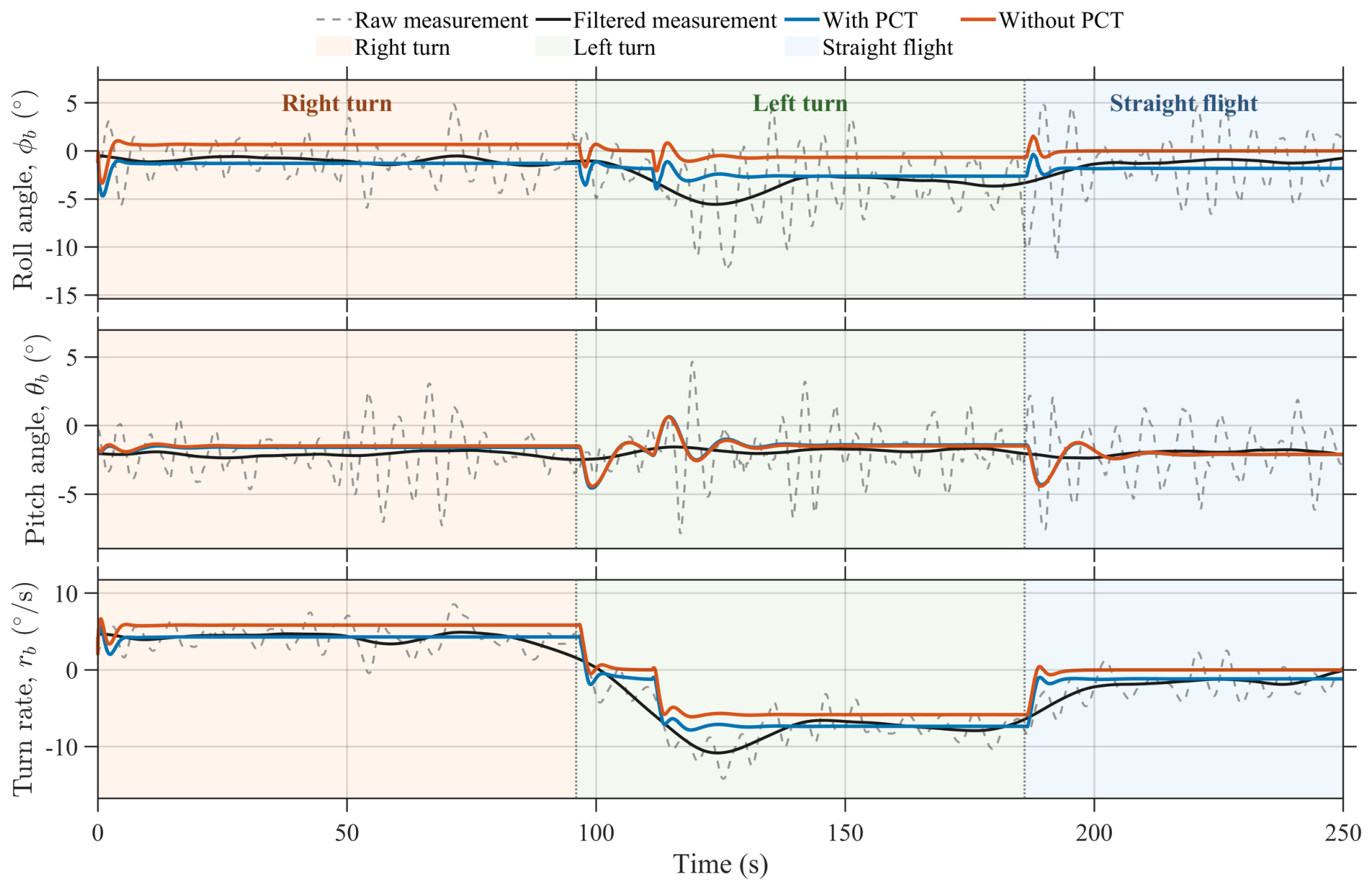
In most dynamic modeling studies of PPV, propeller counter-torque (PCT) is usually neglected in payload dynamics. However, extensive flight tests conducted by the authors revealed an obvious directional control asymmetry during powered flight, namely, the PPV exhibits asymmetric turning responses under nominally symmetric directional control inputs. Comparative flight-test observations further indicate that this asymmetry depends strongly on both the propeller rotation direction and the rotational speed. These results suggest that the directional asymmetry is fundamentally induced by propeller counter-torque. Therefore, this section investigates the physical mechanism by which PCT alters the equilibrium state and leads to directional asymmetry.
3.1. Modeling of Propeller Counter-Torque
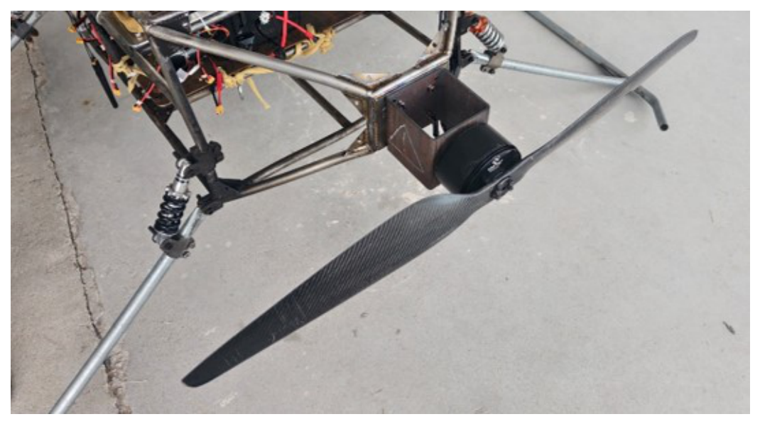
As shown in Figure 6, the propulsion system of the PPV consists of a motor–propeller assembly that simultaneously generates thrust and counter-torque. According to [42], both the propeller thrust and the reaction torque are approximately proportional to the square of the propeller rotational speed.
Figure 6.
Propulsion system.
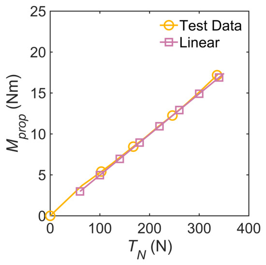
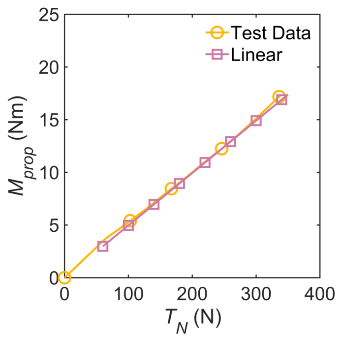
Accordingly, the counter-torque can be approximated as a linear function of thrust, i.e.,
Ground test results support this approximation (Figure 7). Therefore, the above linear relation is adopted in this paper to model the PCT effect in the PPV dynamics. For the propulsion unit considered here, the ground test data show that m. This value indicates that, for the payload, the roll-axis moment generated by the propeller is not negligible during powered flight, particularly during high-thrust maneuvering.
Figure 7.
Validation of the linear relation between and .
Notably, the gyroscopic effect associated with the rotating propeller was also evaluated. For the 42 inch propeller used in the present PPV, with a mass of kg, the gyroscopic moment induced by the payload angular motion during flight was estimated as N·m. Its magnitude is substantially smaller than those of the dominant external moments acting on the PPV. Therefore, the propeller gyroscopic moment is neglected in the subsequent dynamic modeling and analysis.
3.2. Mechanism of PCT-Induced Directional Asymmetry
To clarify the mechanism by which PCT affects the directional characteristics of the PPV, the trim conditions are simplified into the form of Equation (26):
When , namely when PCT is neglected, the influence of symmetric directional control inputs is transmitted mainly through the canopy aerodynamic coefficients, as reflected in Equation (13) and (14). Under this condition, the trim conditions remain directionally symmetric, and the vehicle exhibits symmetric turning response with respect to .
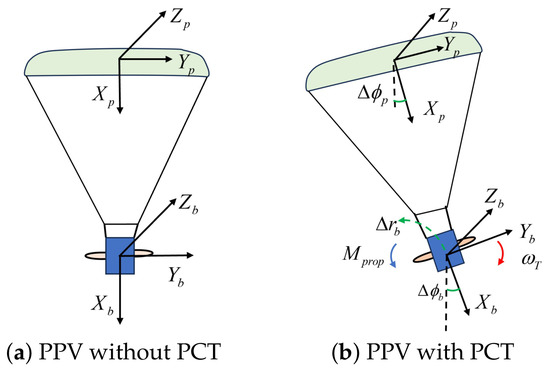
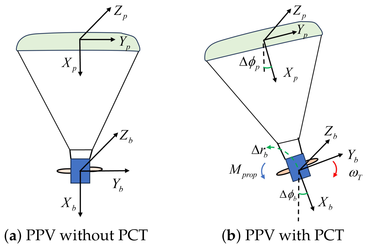
When , however, the trim state is determined jointly by the directional control inputs and the PCT. As reported by [34], a rolling moment can affect both the roll and yaw motion of a parafoil system. In the proposed PPV model, the PCT has similar effects. It shifts the roll–yaw trim states, and results in a turn rate bias even under symmetric control inputs. The mechanism by which PCT shifts the coupled roll–yaw equilibrium is illustrated in Figure 8.
Figure 8.
PCT effect on roll and yaw motion of PPV. PCT simultaneously causes bias in roll angle and turning rate.
To characterize this asymmetry quantitatively, two indicators are introduced. The denotes the steady turn rate when , which reflects the intrinsic turn rates bias produced by PCT. The denotes the compensating directional control input required to maintain straight flight, which measures the control effort needed to offset the PCT-induced trim deviation. These two quantities together provide a compact description of directional asymmetry.
As summarized in Table 3, both and vary systematically with the magnitude of the PCT. Moreover, the effect is more pronounced in climb than in level flight, indicating that the influence of PCT is enhanced at higher-thrust conditions. These results directly demonstrate the relationship between the observed directional asymmetry and the PCT-induced roll moment.
Table 3.
and .
3.3. Quantitative Analysis of PCT Effects
To quantify the effect of PCT on PPV dynamic characteristics, the linearized model in Equation (32) is analyzed about a representative level-flight trim condition , and the corresponding transfer-function representations from to the major state variables are derived.
Based on the resulting transfer functions, the sensitivity of trim states to PCT can be evaluated as shown in Table 4:
Table 4.
Sensitivity of trim states to PCT.
The sensitivity analysis indicates that the dominant influence of PCT is concentrated in the roll angle and turn rate. In contrast, the remaining states are relatively insensitive. This result is physically consistent with the role of PCT as a roll-axis moment input that directly modifies payload attitude and indirectly affects turn rates through lateral–directional coupling.
Taken together, the trim analysis and the linearized sensitivity analysis confirm that PCT is the fundamental physical source of the directional asymmetry observed in PPV powered flight. Specifically, when , the PPV may exhibit a nonzero turning tendency due to PCT. Conversely, if straight flight is desired, a nonzero compensation must be applied to counteract the turn rate bias introduced by the PCT. Among the PPV states, PCT mainly changes lateral and directional states, with minor effects on longitudinal states.
4. Stability Analysis of the Dutch-Roll Mode
This section investigates the local lateral–directional stability of the PPV in the neighborhood of trimmed points. Starting from the trim conditions obtained from the nonlinear Kane’s equations, an analytical linearization is performed to derive the corresponding lateral–directional state-space representation. On this basis, the modal structure of the coupled system is examined, with particular focus on the Dutch-roll mode, which is identified as the dominant oscillatory mode governing lateral–directional stability in powered turning flight. The effects of thrust and directional control inputs are then analyzed. Finally, a damping-ratio-based flight envelope is established to determine the admissible maneuver region for powered turning flight.
4.1. Lateral–Directional State-Space Equations
The nonlinear equations of motion derived from Kane’s equations are analytically linearized about steady trim conditions. Since Kane’s equations avoid the explicit appearance of internal constraint forces, the resulting Jacobian matrices preserve the structural characteristics of the dynamic model and provide a mathematically consistent basis for modal analysis. In the present study, the purpose of the linearization is to characterize the local oscillatory stability of the nonlinear trim family over the maneuvering domain. Because the present section focuses on local lateral–directional stability, the full linearized system in Equation (32) is partitioned into a lateral–directional subsystem:
where denotes the associated lateral–directional states. This equation is used to identify the dominant oscillatory modes and quantify their variation under different maneuver conditions. The analytical linearization provides the mathematical foundation for the following modal analysis. In particular, it enables the direct extraction of the Dutch-roll eigenstructure from , allowing investigation of the influence of thrust and directional control on the local oscillatory stability of PPV.
4.2. Identification of the Dutch-Roll Mode
The local lateral–directional stability characteristics are determined by the eigenstructure of . For the PPV considered in this study, the lateral–directional subsystem generally contains one dominant oscillatory complex–conjugate mode together with other non-oscillatory or weakly oscillatory modes. Among them, the complex–conjugate pair associated with the coupled roll–yaw motion of the payload is identified as the Dutch-roll mode.
Unlike the Dutch-roll mode of a conventional rigid aircraft, the Dutch-roll mode of the PPV is affected not only by aerodynamic derivatives but also by canopy–payload coupling, trim-state variation, and propulsion-related effects. It therefore exhibits strong dependence on the maneuver condition.
Denoting the Dutch-roll eigenvalues by the following:
The corresponding damping ratio is defined as follows:
This damping ratio is adopted as the principal indicator of lateral–directional stability in the subsequent analysis. A larger indicates faster attenuation of the coupled roll–yaw oscillation, whereas a smaller damping ratio indicates weaker damping and a stronger tendency toward persistent oscillatory motion. Because this mode corresponds directly to the oscillatory phenomenon observed in powered flight tests, it is treated as the critical mode for subsequent analysis and flight-envelope construction.
4.3. Dutch-Roll Evolution with Thrust and Directional Control
The Dutch-roll characteristics of the PPV are associated with trim conditions. Variations in thrust and directional control modify the trim states and then alter the local Jacobian matrix , leading to systematic changes in the Dutch-roll eigenvalues. The following two subsections examine these effects separately with thrust and directional control treated as the primary maneuver parameters.
4.3.1. Effect of Thrust
The trim state primarily mediates the effect of thrust on the Dutch-roll mode. As thrust increases, the longitudinal equilibrium changes, including the payload pitch attitude, forward velocity, and canopy–payload coupling loads. These changes are reflected in the lateral–directional Jacobian and, consequently, modify the oscillatory characteristics of the system.
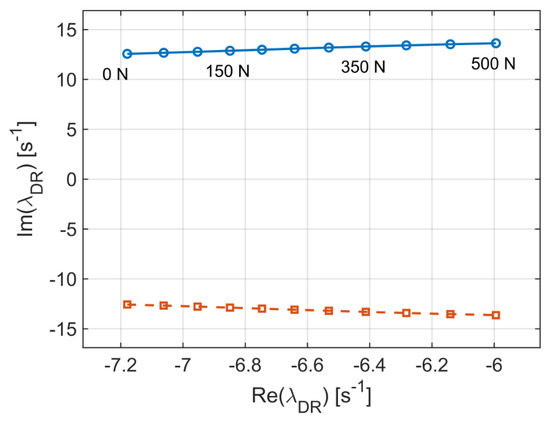
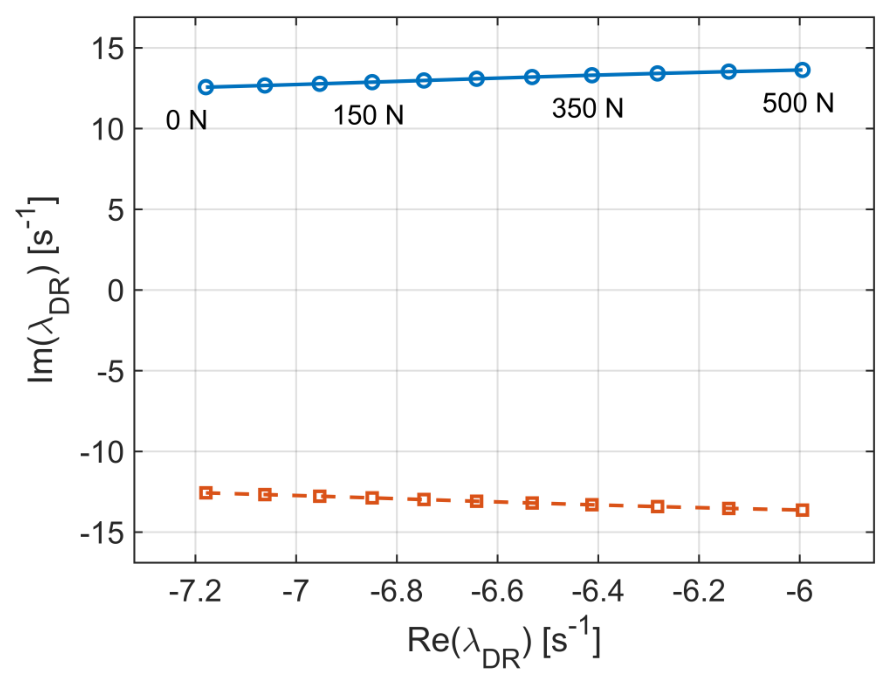
Figure 9 shows the locus of the Dutch-roll poles under varying thrust. Increasing thrust generally drives the poles toward the imaginary axis and reduces the Dutch-roll damping ratio. This trend becomes especially pronounced under climb conditions. From a physical standpoint, this explains why the oscillatory motion observed in powered climb tends to decay more slowly than that in near-level flight.
Figure 9.
Pole locus under varying . Increasing thrust shifts the poles toward a lower-damping region, indicating degraded PPV stability and a higher tendency for Dutch-roll excitation.
4.3.2. Effect of Directional Control
In addition to thrust, the directional control input also plays an important role in Dutch-roll analysis. changes the steady-turn trim state, thereby modifying the local lateral–directional dynamics. For each value of , a steady-turn trim state is first computed, after which the corresponding matrix is evaluated and the Dutch-roll eigenvalues are extracted.
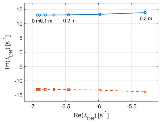
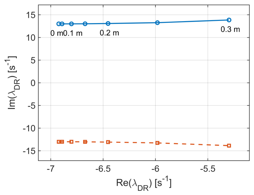
Figure 10 shows the locus of the Dutch-roll poles under varying . The results indicate that directional control can interact strongly with the Dutch-roll mode, as the maneuver input shifts the local equilibrium. Consequently, the Dutch-roll damping ratio is a parameter that varies simultaneously with propulsion and directional control. This observation is especially important for powered turning flight, where large directional control combined with high thrust may significantly reduce oscillatory damping.
Figure 10.
Pole locus under varying . Increasing shifts the Dutch-roll poles toward a lower-damping region, indicating reduced PPV stability.
4.3.3. Dutch-Roll Damping-Based Flight Envelope
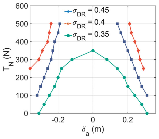
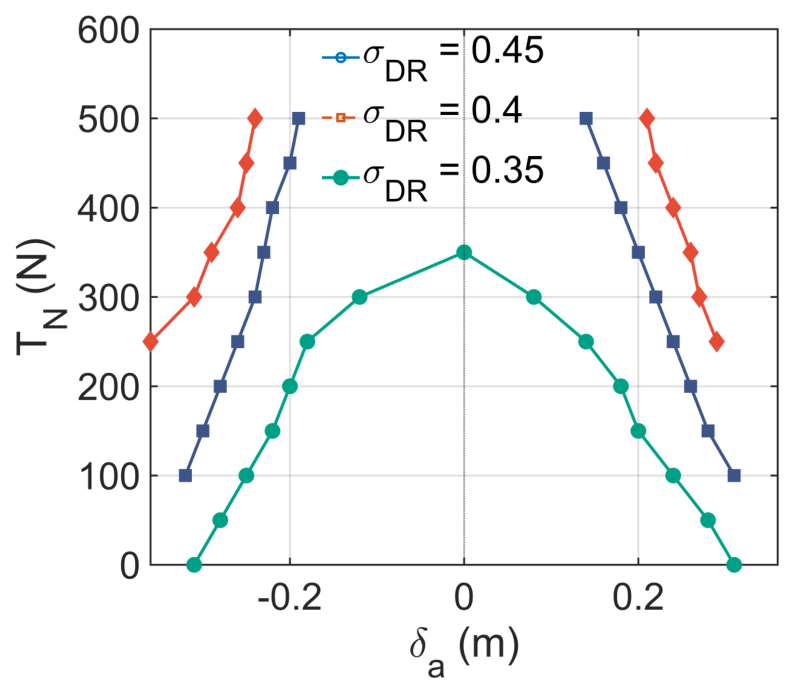
Once the Dutch-roll mode has been identified and its sensitivity to thrust and directional control inputs has been clarified, the modal analysis can be translated into an engineering stability boundary. In this study, the Dutch-roll damping ratio is selected as the evaluation metric for the lateral–directional dynamic characteristics of the PPV. Since no specific damping-ratio criterion has been established for PPVs, three representative damping levels are considered to characterize different stability requirements. These values are selected as engineering reference levels rather than strict stability limits.
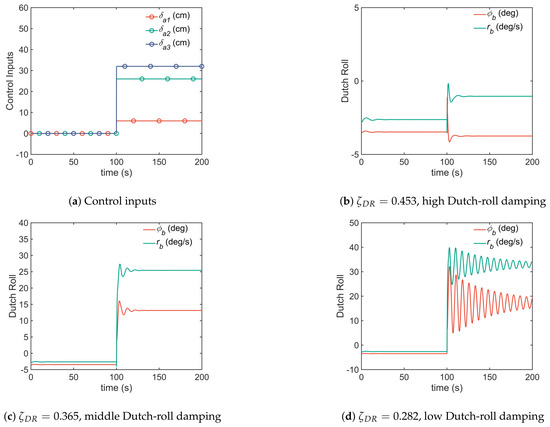
The lower level, , is chosen to represent a relatively weakly damped Dutch-roll mode, while 0.40 and 0.45 correspond to progressively improved damping characteristics. The influence of these damping levels on the lateral–directional response is further examined through nonlinear simulations in Section 5.4. In this way, the flight envelope is represented here by a family of iso-damping contours.
Figure 11 has a clear physical interpretation. As thrust increases, the Dutch-roll poles move toward the imaginary axis and the damping ratio decreases, so the allowable directional control range contracts accordingly. As a result, directional control commands that remain acceptable in low-thrust or near-level-flight conditions may cross the low-damping boundary during climb and induce slowly decaying roll–yaw oscillations. The resulting flight envelope is a dynamic-stability boundary defined by the damping characteristics of the dominant lateral–directional mode. This makes it directly relevant to flight control, autopilot design, and powered-turn safety assessment.
Figure 11.
Reference flight envelope based on the Dutch-roll damping-ratio constraint.
4.4. Sensitivity of Dutch-Roll Characteristics to System Parameters
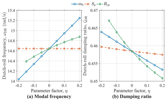
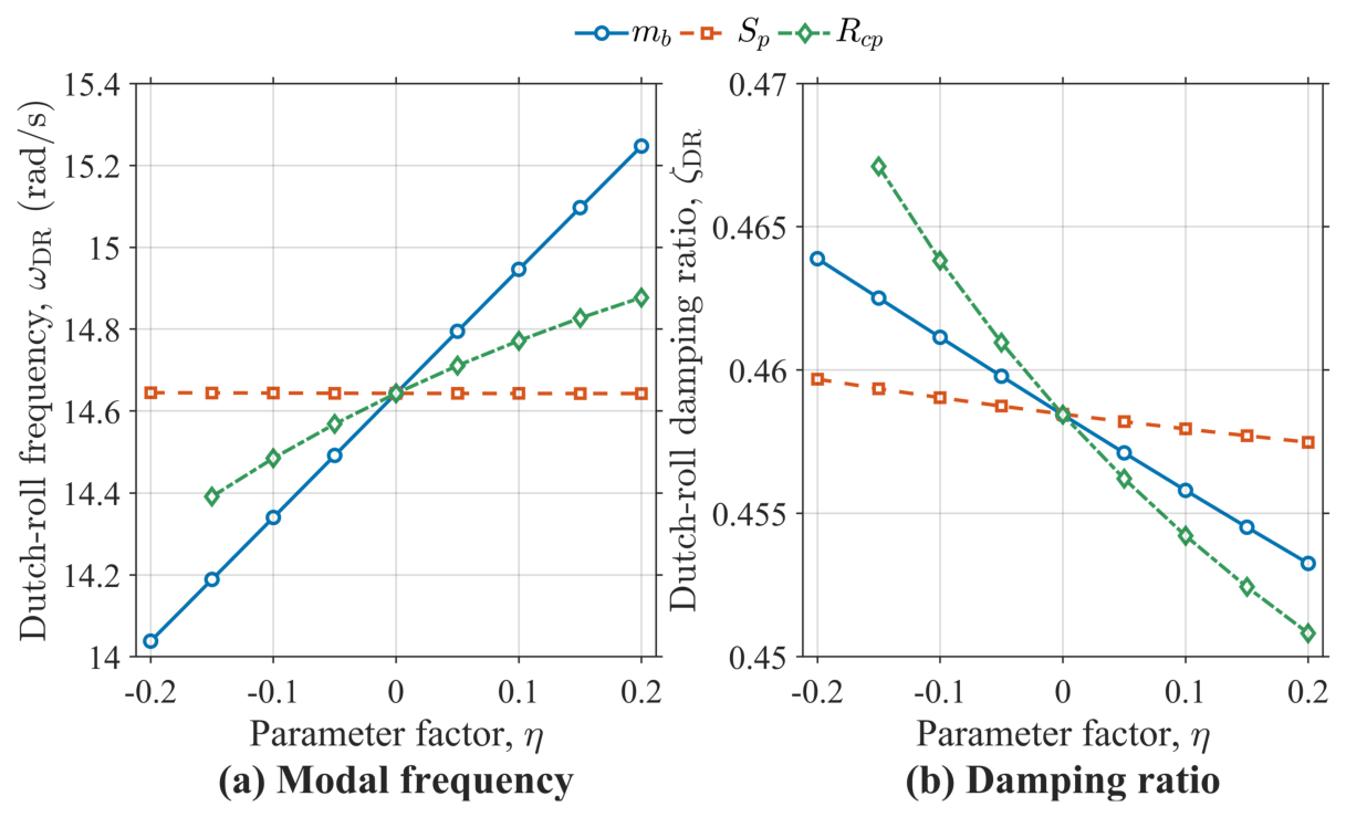
In addition to the propulsion and control conditions investigated above, the Dutch-roll characteristics are also affected by the physical configuration of the PPV. To further examine this dependence, a parametric sensitivity analysis is conducted for three representative system parameters: the parafoil area , payload mass , and canopy–payload distance . These parameters characterize, respectively, the aerodynamic loading, payload loading, and geometric coupling between the canopy and payload. The nominal values listed in Table 1 are taken as the reference values.
For each parameter , a normalized variation factor is defined as follows:
where denotes the nominal value. Each parameter is independently varied from to , while the remaining parameters are maintained at their nominal values. For each variation, the steady-flight trim condition is recomputed, followed by linearization of the nonlinear model about the updated trim state. The corresponding Dutch-roll eigenvalues are then extracted to determine the damping ratio and modal frequency . This procedure accounts for both the direct parameter dependence of the dynamics and the associated shift in the equilibrium condition.
To quantitatively compare the relative influence of different parameters, the normalized local sensitivities of the Dutch-roll damping ratio and modal frequency are defined as follows:
Figure 12 shows the variation in the Dutch-roll damping ratio with , , and . The results indicate that has the strongest influence on , with the damping ratio decreasing as this parameter increases. In comparison, the influence of is relatively moderate, whereas variations in produce only limited changes within the investigated range. Unlike the damping ratio, the modal frequency exhibits stronger sensitivity to . The corresponding normalized sensitivity coefficients are summarized in Table 5, providing a quantitative comparison of the relative contributions of the three parameters to Dutch-roll damping.
Figure 12.
Parameter effects on Dutch-roll mode.
Table 5.
Normalized sensitivities of Dutch-roll characteristics to key system parameters.
Overall, the sensitivity analysis demonstrates that the Dutch-roll characteristics identified for the nominal PPV configuration are dependent on both aerodynamic loading and canopy–payload multibody properties. In particular, variations in and modify the effective wing loading and the resulting trim condition, while affects the geometric coupling between the canopy and payload.
5. Numerical Simulations and Flight-Test Validation
This section validates the proposed modeling and analysis framework through numerical simulations and flight-test comparisons. First, Kane’s formulation with quasi-velocities is compared with Newton–Euler and Lagrange formulations under identical simulation conditions to examine the consistency of the derived equations and their computational characteristics. Subsequently, the predictive capability of the nonlinear 9-DOF Kane-based model is assessed using flight-test data. Furthermore, the mechanism and quantitative trends of PCT-induced directional asymmetry are verified using both trim analysis and time-domain response comparison. Additionally, the Dutch-roll stability analysis developed in Section 4 is validated by comparing nonlinear oscillatory responses under different thrust and directional control conditions.
5.1. Comparative Evaluation of Varying Dynamic Modeling Formulations
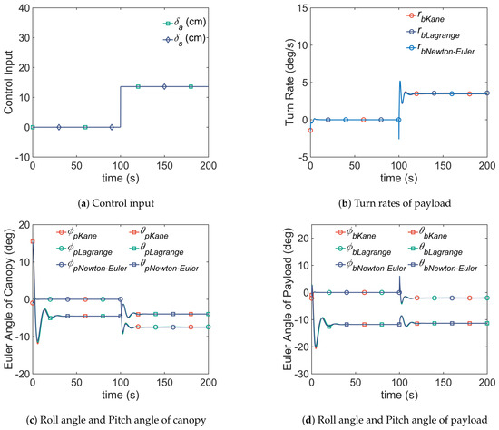
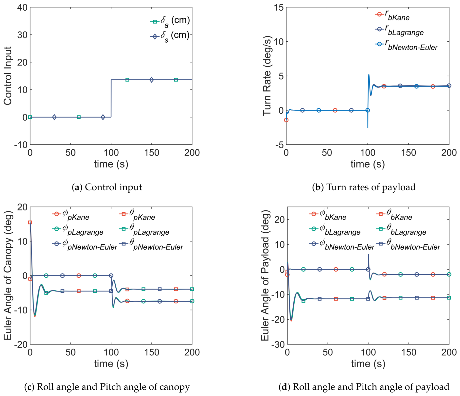
To further verify the correctness and computational characteristics of the proposed Kane-based multibody formulation, a comparative simulation study is conducted among three dynamic formulations: the Kane formulation with quasi-velocities, the Newton–Euler formulation with constraint reactions, and the Lagrange formulation. All three formulations are established using the same system parameters in Table 1 and Table 2.
Figure 13 shows the time-domain responses of principal states obtained from the three formulations. It can also be observed that the responses predicted by the Kane, Newton–Euler, and Lagrange formulations are in close agreement throughout the simulation interval.
Figure 13.
Comparative simulation of different dynamic methods.
The computational efficiency of the three formulations is further evaluated by comparing their execution time. For each formulation, the simulation is repeated 10 times under the same solver configuration. The average execution time is then recorded to reduce the influence of random fluctuations caused by operating-system scheduling and background processes.
Table 6 lists the average execution time of the three formulations. Compared with the Newton–Euler and Lagrange formulations, the Kane formulation requires a shorter execution time. The improvement is mainly attributed to the compact structure of Kane’s equations and the use of quasi-velocities. Since the internal constraint forces are eliminated through projection onto the partial velocities, the resulting equations avoid the explicit solution of constraint forces. This feature reduces the algebraic complexity of the multibody dynamic formulations and improves the computational efficiency of the simulation.
Table 6.
Execution time comparison among different dynamic modeling formulations.
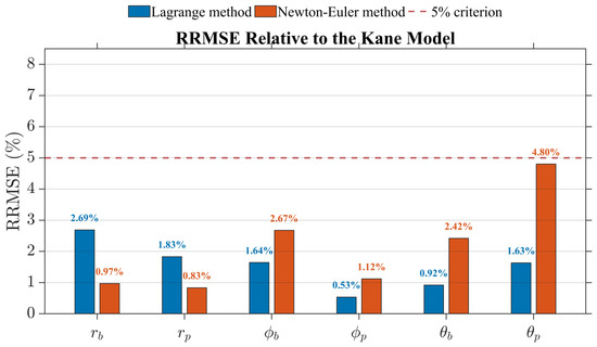
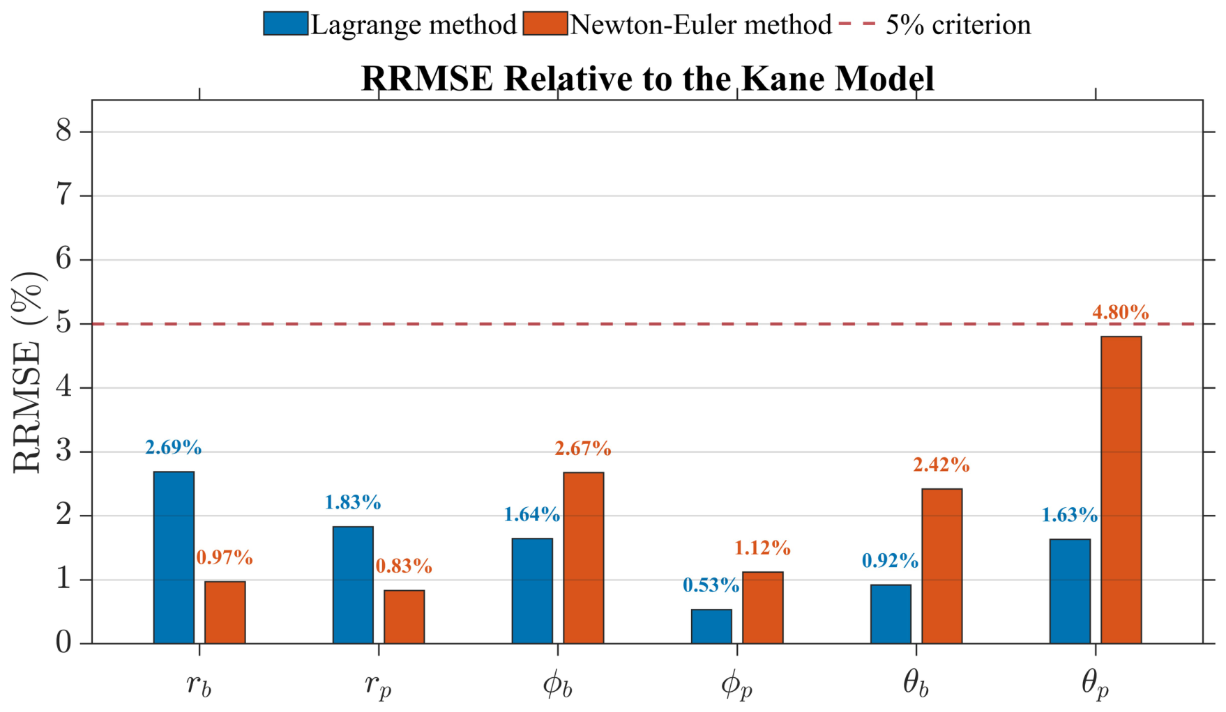
As Figure 13 and Figure 14 show, the comparative study demonstrates that Kane’s formulation, the Newton–Euler formulation, and the Lagrange formulation produce consistent nonlinear dynamic responses for the same PPV. Notably, Kane’s formulation with quasi-velocities provides a natural basis for trim-consistent linearization, which is essential for the subsequent analysis of PCT-induced directional asymmetry and Dutch-roll stability.
Figure 14.
Relative RMSE (RRMSE) of each state.
5.2. Validation of Model Fidelity and Local Linearization Accuracy
To assess the predictive capability of the proposed nonlinear model, two representative flight conditions, namely level flight and climb, are selected for comparison with flight-test data. The flight-test measurements are obtained from an onboard GPS/IMU unit (Figure 15).
Figure 15.
Flight tests conducted in July 2025 at an altitude of roughly 700 m.
As Figure 16 shows, in level flight (), the simulation reproduces the measured payload pitch and roll behavior. The payload pitch angle stabilizes around −0.9° and the roll angle remains biased at approximately −2.13°, reflecting the influence of PCT. The simulated turn rate response under differential control input matches the measured asymmetric turning behavior, confirming that the proposed model captures the observed directional control asymmetry.
Figure 16.
Level-flight maneuver ( N).
As Figure 17 shows, for the climb condition (), the nonlinear model also reproduces the measured trends: the payload pitch angle increases to about 5.36°, and the roll angle bias grows in magnitude to about −4.22° due to more substantial PCT effects at higher thrust. The turning response exhibits even more pronounced asymmetry, which the model correctly predicts. Across both cases, the agreement between simulated and measured data confirms that Kane’s formulation provides an accurate description of PPV motion in both longitudinal and lateral channels.
Figure 17.
Climb maneuver ( N).
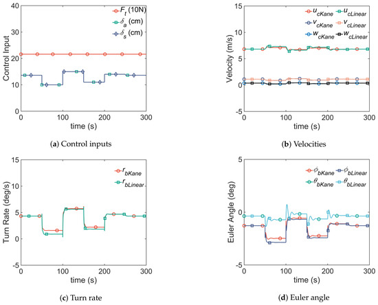
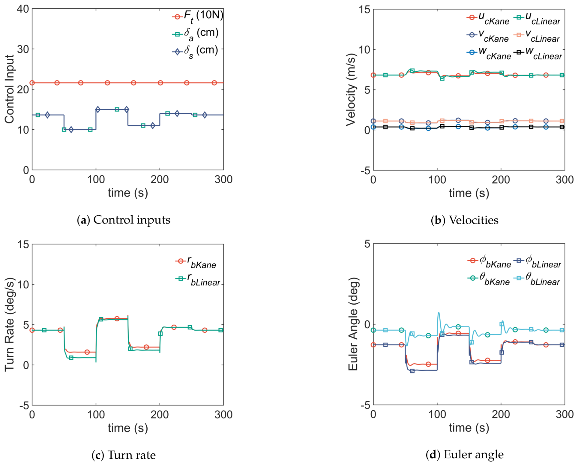
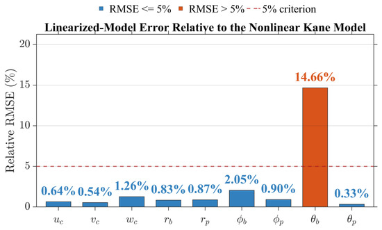
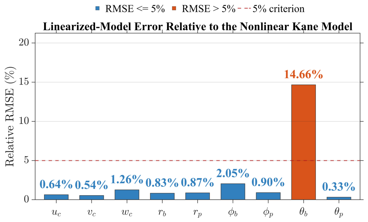
To verify the accuracy of the analytical linearization, the responses of the linearized model are compared with those of the nonlinear Kane-based model around representative trim conditions (as shown in Figure 18 and Figure 19).
Figure 18.
Validation of the linearized model.
Figure 19.
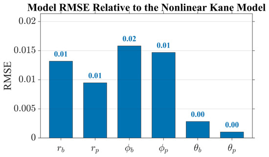
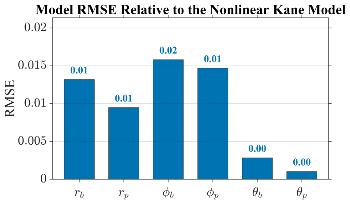
Relative RMSE of each state.
Under the same initial perturbations and control inputs, both models exhibit closely matched trends in the major state variables. The relative RMSE results indicate that the linearized model captures the dominant local dynamics of the nonlinear system with satisfactory accuracy near the trim point. Most state variables exhibit RRMSE values below , while the relatively larger errors in some angular states remain within an acceptable range due to their smaller absolute magnitudes. This agreement confirms that the analytical linearization is sufficiently accurate for local stability analysis, modal identification, and the subsequent Dutch-roll-based flight-envelope calculation.
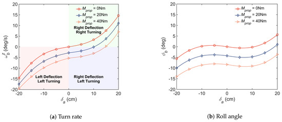
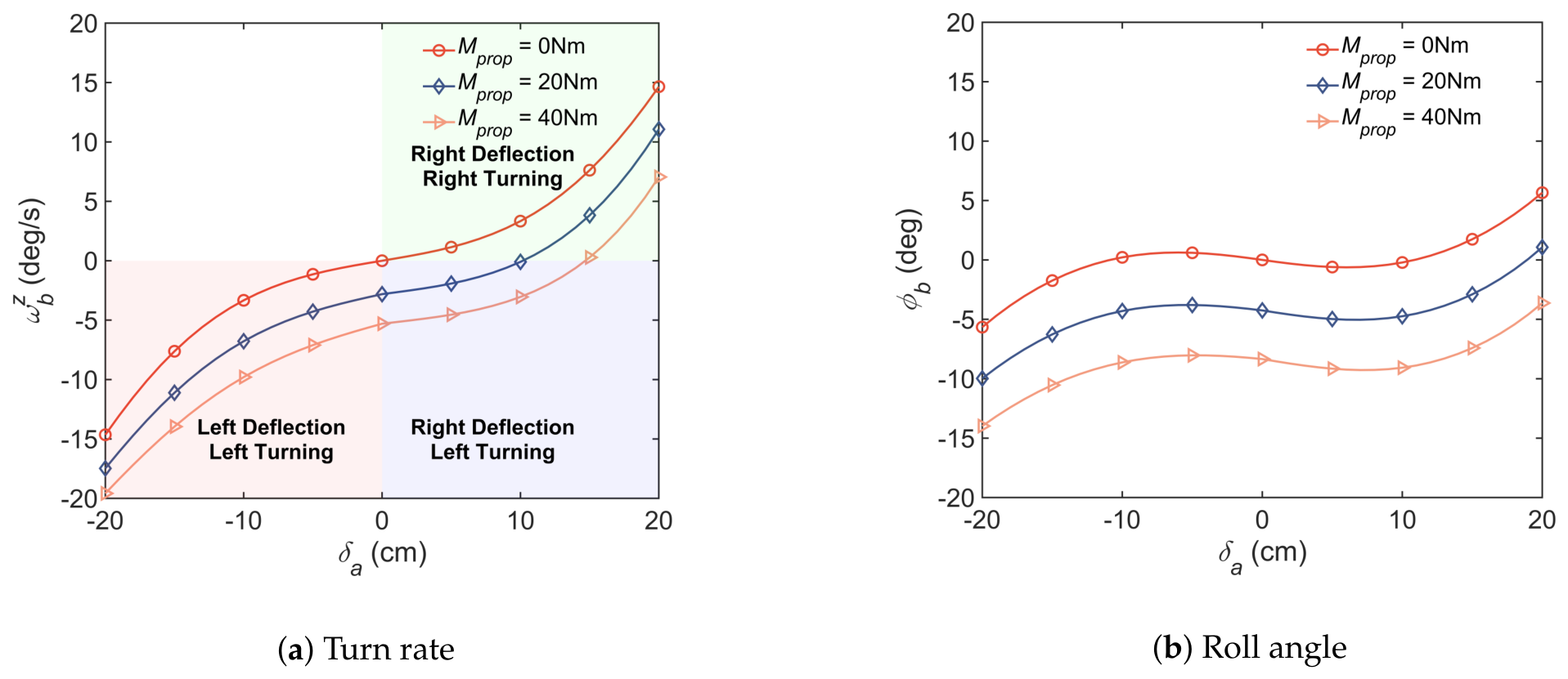
5.3. Validation of PCT-Induced Directional Asymmetry
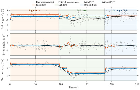
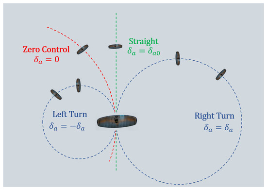
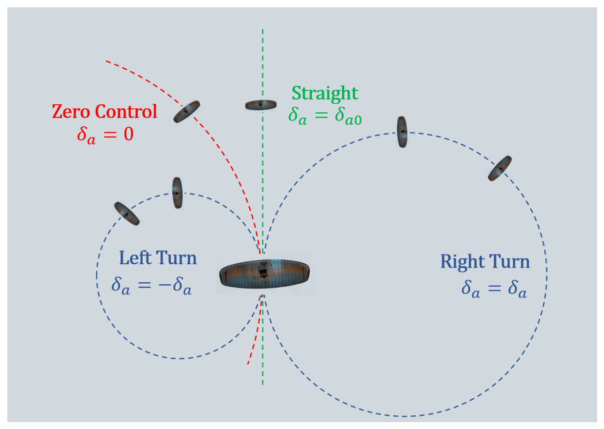
This subsection validates the PCT-induced directional asymmetry (as shown in Figure 20) through trim analysis and time-domain simulations. The trim analysis is used to compute the steady lateral–directional states under different directional control inputs and PCT levels, thereby illustrating the equilibrium shift induced by PCT. Then, the analysis results in Section 3.3 are compared with the time-domain simulations.
Figure 20.
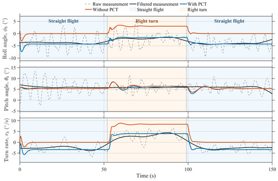
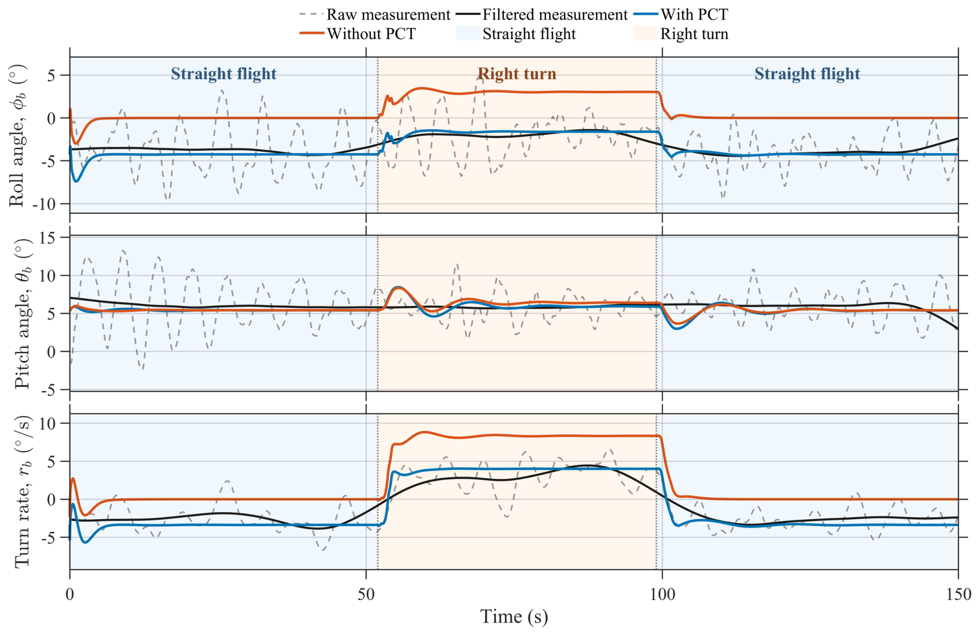
Directional asymmetry phenomenon.
As Figure 21 shows, the trim analysis results confirm that the PPV indeed exhibits an obvious directional asymmetry during powered flight, and that the magnitude and direction of this asymmetry depend directly on the sign and magnitude of PCT. The consistency between the trim calculations and the linearized sensitivity analysis in Section 3 provides strong support for the conclusion that PCT is the dominant physical source of the observed directional asymmetry.
Figure 21.
Directional asymmetry trim analysis.
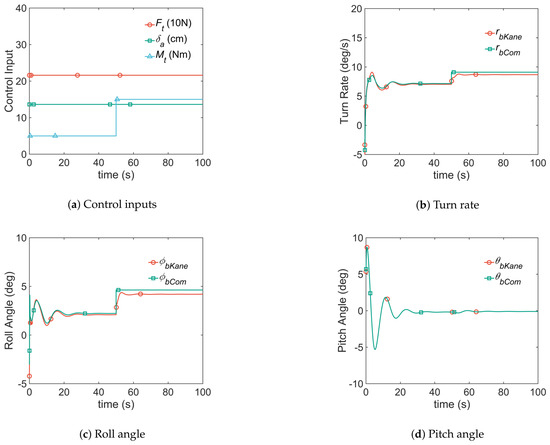
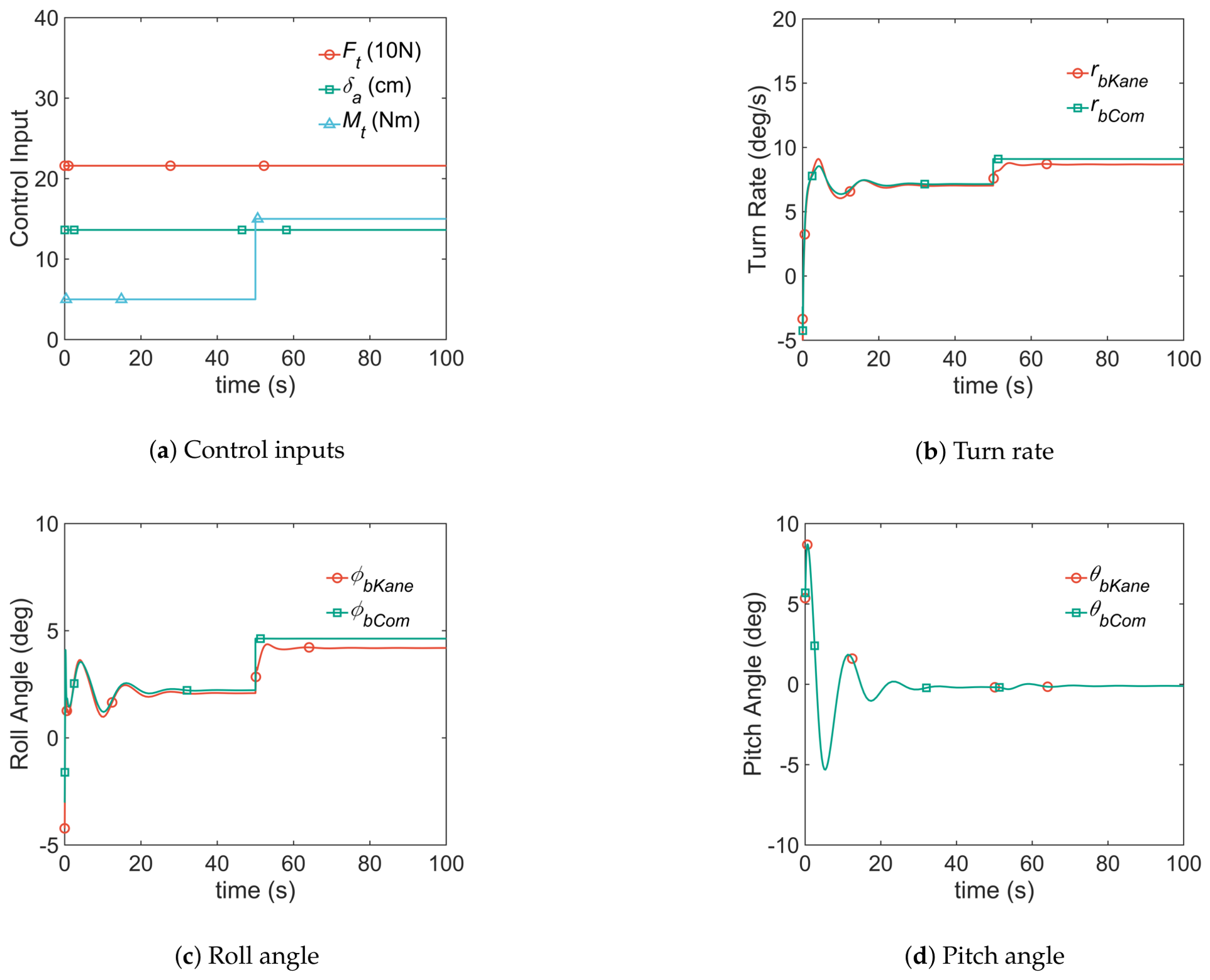
To further verify the predictive capability of the linearized analysis, an additional time-domain comparison is conducted between the nonlinear dynamic model and the compensated model (as shown in Figure 22). The corresponding RMSE statistics show that the response trend predicted by the PCT sensitivity analysis is retained in the nonlinear simulation (as shown in Figure 23).
Figure 22.
Validation of PCT effect compensation. “Kane” denotes the Kane’s equations with PCT, “Com” denotes the Kane-based model with PCT compensation.
Figure 23.
RMSE of PCT effect compensation.
Overall, the consistency among flight-test observations, trim calculations, and time-domain simulations provides strong evidence that PCT is the dominant physical source of the directional asymmetry observed in the present PPV.
5.4. Validation of Stability Analysis for Dutch-Roll
To validate the modal analysis developed in Section 4, the time-domain responses of the nonlinear model are examined under different thrust and directional control conditions, and the resulting oscillatory behavior is compared with the Dutch-roll predictions obtained from the linearized lateral–directional model.
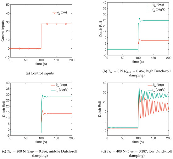
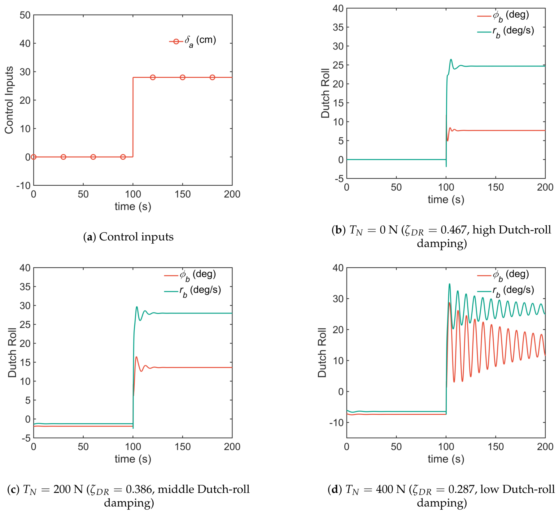
First, under the same directional control command, the lateral–directional responses are compared for different thrust levels. Figure 24 shows that the alternating roll–yaw oscillation becomes progressively more persistent and the attenuation rate decreases as thrust increases. This behavior is consistent with the modal analysis, which predicts that the Dutch-roll damping ratio decreases as the operating point shifts toward higher-thrust conditions.
Figure 24.
Dutch-roll comparison under varying .
Then, under a fixed thrust level, the lateral–directional responses are compared for different directional control inputs. Figure 25 shows that larger directional control inputs lead to lower Dutch-roll damping and more obvious oscillatory behavior. These results confirm that the maneuver command alters the trim state and thereby changes the local oscillatory stability of the coupled canopy–payload system.
Figure 25.
Dutch-roll comparison under varying ( N).
Overall, the time-domain simulations are in close agreement with the modal predictions. Trim points located in the higher-damping region exhibit well-attenuated lateral–directional responses and satisfactory stability margins. In contrast, conditions approaching the low-damping contours tend to generate slowly decaying roll–yaw oscillations and stronger sensitivity to directional control input. These results provide direct validation of the Dutch-roll damping-based flight envelope and indicate that, during powered flight, the PPV should be maneuvered within the reference envelope to avoid severe attitude oscillations associated with insufficient Dutch-roll damping.
6. Discussion
The results have several implications for the dynamic analysis and controller design of PPVs. First, the Kane’s equations provide a compact and structurally consistent basis for subsequent trim computation, analytical linearization, and stability analysis. Second, the directional asymmetry analysis demonstrates that the roll-axis moment generated by PCT shifts the coupled roll–yaw equilibrium and produces asymmetric directional responses. Consequently, neglecting PCT may lead to biases in predictions of steady coordinated turn behavior during powered flight. Finally, the Dutch-roll analysis shows that the lateral–directional stability of the PPV depends on both the control inputs and the system parameters. The damping ratio decreases under high-thrust and large directional control inputs, while variations in , , and further modify the modal characteristics.
The applicability of the present model is limited to the normal flight regime in which the canopy remains fully inflated and the aerodynamic states remain away from stall. The rigid-canopy assumption and low-order aerodynamic representation do not explicitly capture large canopy deformation, flow separation, unsteady aerodynamic effects, or nonlinear variations in aerodynamic derivatives. Consequently, the model does not represent severe oscillations or stall behavior arising from large angles of attack, aggressive control deflections, or other limiting flight conditions.
From a control perspective, the PCT-induced directional asymmetry and Dutch-roll analysis provide useful information for both autonomous and human-operated PPVs. For autonomous systems, the PCT-induced equilibrium shift can be incorporated into feedforward compensation, while the damping-ratio-based flight envelope can be used to constrain thrust and directional control inputs in low-damping operating regions. For human-operated or training systems, this dynamic model may also provide a physics-based simulation environment for evaluating pilot responses. In combination with human-in-the-loop interfaces or training devices, such as motion-feedback or exoskeleton-assisted systems, the model could support the investigation of operator–vehicle interaction. Data-driven or neural-network-based controllers may further complement the physics-based model by compensating for nonlinear and unmodeled effects outside the nominal operating region.
7. Conclusions
This paper has presented a multibody dynamic analysis framework for a powered parafoil vehicle based on Kane’s method with quasi-velocities. A 9-DOF nonlinear model was established to describe the relative motion between the canopy and the payload while avoiding the explicit appearance of internal constraint forces. Based on the resulting trim conditions, an analytical linearization was derived directly from the Kane’s equations, which provides a structurally consistent basis for local modal analysis of the PPV around trim points.
The obtained results clarify several key dynamic characteristics of powered flight. First, the propeller counter-torque is essential for reproducing the directional asymmetry observed in flight tests. The analysis shows that PCT shifts the coupled roll–yaw equilibrium, indicating that PCT is the dominant physical source of the directional asymmetry observed in the present PPV. Second, the Dutch-roll mode is identified as the dominant oscillatory mode governing local lateral–directional stability. The modal analysis shows that increasing thrust moves the Dutch-roll poles toward the imaginary axis and reduces the corresponding damping ratios. At the same time, a directional control input further modifies the local equilibrium and alters the oscillatory characteristics. On this basis, a damping-ratio-based flight envelope was constructed, providing an interpretable stability boundary for powered turning flight.
The comparative evaluation demonstrates the consistency and computational efficiency of the Kane-based formulation. The proposed framework was further examined through simulations and flight-test validation under representative level-flight and climb conditions. The results show that the nonlinear Kane-based model reproduces the pitch, roll, and turn rate responses, and that the linearization preserves the dominant local dynamics near trim points. These findings indicate that the proposed modeling and analysis framework is suitable not only for mechanism interpretation and stability assessment, but also for subsequent observer development and flight control design of PPV.
Author Contributions
Conceptualization, W.Z. and W.H.; methodology, W.Z. and W.H.; software, W.Z.; validation, W.Z. and Y.D.; formal analysis and investigation, W.Z., C.D., Y.D., M.L. and Y.F.; writing—original draft preparation, W.Z.; writing—review and editing, W.Z. and W.H.; supervision, W.H. and Y.D. All authors have read and agreed to the published version of the manuscript.
Funding
This research received no external funding.
Data Availability Statement
The data supporting the findings of this study are not publicly available due to institutional restrictions and confidentiality requirements related to the flight-test dataset.
Acknowledgments
The authors would like to express their gratitude to EditSprings (https://www.editsprings.com) for the expert linguistic services provided.
Conflicts of Interest
The authors declare no conflicts of interest.
Nomenclature
| Payload mass and canopy mass | kg | |
| Canopy area | m2 | |
| Distance from connection point to CG | m | |
| Asymmetric trailing-edge deflection | m | |
| Symmetric trailing-edge deflection | m | |
| Angular rates of payload and canopy | rad/s | |
| Propeller thrust | N | |
| Propeller counter-torque | N·m | |
| Dutch-roll damping ratio | – | |
| Dutch-roll natural frequency | rad/s | |
| Longitudinal aerodynamic coefficients of canopy | – | |
| Lateral aerodynamic coefficients of canopy | – |
References
- Sun, Q.; Yu, L.; Zheng, Y.; Tao, J.; Sun, H.; Sun, M.; Dehmer, M.; Chen, Z. Trajectory tracking control of powered parafoil system based on sliding mode control in a complex environment. Aerosp. Sci. Technol. 2022, 122, 107406. [Google Scholar] [CrossRef] [Scilit]
- Xing, X.; Yang, W.; Qin, L.; Xiao, B.; Yang, F. Finite-Time Prescribed Performance Fault-Tolerant Attitude Control for Rocket Substage Recovery by Parafoil. IEEE Trans. Ind. Electron. 2025, 73, 1341–1351. [Google Scholar] [CrossRef] [Scilit]
- Ye, F.; Jiang, X.; Luo, Y.; Li, S.; Ji, Y.; Zhong, S.; Sun, G. Mixed uncertainty quantification for terminal flight state of Mars atmospheric entry. Acta Astronaut. 2022, 199, 183–194. [Google Scholar] [CrossRef] [Scilit]
- Suhir, E. Landing on Mars: Probabilistic modeling enables quantifying the last “six minutes of terror”. Acta Astronaut. 2021, 179, 680–684. [Google Scholar] [CrossRef] [Scilit]
- Yu, Z.; Sun, H.; Sun, Q.; Tan, P.; Chen, Z.; Qu, J. Dynamic path planning for parafoil homing in surface wind disturbance environment. IEEE Trans. Autom. Sci. Eng. 2025, 22, 15045–15059. [Google Scholar] [CrossRef] [Scilit]
- Yang, J.; Tan, P.; Sun, Q.; Sun, H.; Tao, J.; Fei, Z.; Chen, Z. Dual-loop linear active disturbance rejection control for parafoil airdrop systems in wind environment. Aerosp. Sci. Technol. 2025, 158, 109910. [Google Scholar] [CrossRef] [Scilit]
- Zhu, H.; Sun, Q.; Liu, X.; Liu, J.; Sun, H.; Wu, W.; Tan, P.; Chen, Z. Fluid–structure interaction-based aerodynamic modeling for flight dynamics simulation of parafoil system. Nonlinear Dyn. 2021, 104, 3445–3466. [Google Scholar] [CrossRef] [Scilit]
- Zhu, H.; Sun, Q.; Tao, J.; Chen, Z.; Dehmer, M.; Xie, G. Flexible modeling of parafoil delivery system in wind environments. Commun. Nonlinear Sci. Numer. Simul. 2022, 108, 106210. [Google Scholar] [CrossRef] [Scilit]
- Jann, T. Aerodynamic model identification and GNC design for the parafoil-load system ALEX. In Proceedings of the 16th AIAA Aerodynamic Decelerator Systems Technology Conference and Seminar, Boston, MA, USA, 21–24 May 2001; p. 2015. [Google Scholar]
- Mortaloni, P.; Yakimenko, O.; Dobrokhodov, V.; Howard, R. On the development of a six-degree-of-freedom model of a low-aspect-ratio parafoil delivery system. In Proceedings of the 17th AIAA Aerodynamic Decelerator Systems Technology Conference and Seminar, Monterey, CA, USA, 19–22 May 2003; p. 2105. [Google Scholar]
- Yakimenko, O. On the development of a scalable 8-DoF model for a generic parafoil-payload delivery system. In Proceedings of the 18th AIAA Aerodynamic Decelerator Systems Technology Conference and Seminar, Munich, Germany, 23–26 May 2005; p. 1665. [Google Scholar]
- Slegers, N.; Costello, M. Aspects of control for a parafoil and payload system. J. Guid. Control. Dyn. 2003, 26, 898–905. [Google Scholar] [CrossRef] [Scilit] [PubMed]
- Slegers, N.J. Effects of canopy-payload relative motion on control of autonomous parafoils. J. Guid. Control. Dyn. 2010, 33, 116–125. [Google Scholar] [CrossRef] [Scilit]
- Slegers, N.; Gorman, C. Comparison and analysis of multi-body parafoil models with varying degrees of freedom. In Proceedings of the 21st AIAA Aerodynamic Decelerator Systems Technology Conference and Seminar, Dublin, Ireland, 23–26 May 2011; p. 2615. [Google Scholar]
- Zhu, E.; Sun, Q.; Tan, P.; Chen, Z.; Kang, X.; He, Y. Modeling of powered parafoil based on Kirchhoff motion equation. Nonlinear Dyn. 2015, 79, 617–629. [Google Scholar] [CrossRef] [Scilit]
- Tan, P.; Sun, M.; Sun, Q.; Chen, Z. Dynamic modeling and experimental verification of powered parafoil with two suspending points. IEEE Access 2020, 8, 12955–12966. [Google Scholar] [CrossRef] [Scilit]
- Prakash, O.; Ananthkrishnan, N. Modeling and simulation of 9-DOF parafoil-payload system flight dynamics. In Proceedings of the AIAA Atmospheric Flight Mechanics Conference and Exhibit, Keystone, CO, USA, 21–24 August 2006; p. 6130. [Google Scholar]
- Luo, S.; Sun, Q.; Sun, M.; Tan, P.; Wu, W.; Sun, H.; Chen, Z. On decoupling trajectory tracking control of unmanned powered parafoil using ADRC-based coupling analysis and dynamic feedforward compensation. Nonlinear Dyn. 2018, 92, 1619–1635. [Google Scholar] [CrossRef] [Scilit]
- Zheng, Y.; Tao, J.; Sun, Q.; Zeng, X.; Sun, H.; Sun, M.; Chen, Z. DDPG-based active disturbance rejection 3D path-following control for powered parafoil under wind disturbances. Nonlinear Dyn. 2023, 111, 11205–11221. [Google Scholar] [CrossRef] [Scilit]
- Tao, J.; Sun, Q.; Tan, P.; Chen, Z.; He, Y. Active disturbance rejection control (ADRC)-based autonomous homing control of powered parafoils. Nonlinear Dyn. 2016, 86, 1461–1476. [Google Scholar] [CrossRef] [Scilit]
- Redelinghuys, C. A flight simulation algorithm for a parafoil suspending an air vehicle. J. Guid. Control. Dyn. 2007, 30, 791–803. [Google Scholar] [CrossRef] [Scilit]
- Long, X.; Sun, M.; Chen, Z. Dynamic modeling and stability analysis of parafoil traction cable for high altitude wind power generation. In Structures; Elsevier: Amsterdam, The Netherlands, 2023; Volume 58, p. 105454. [Google Scholar]
- Bingbing, L.; Yuqing, H.; Jianda, H.; Jizhong, X. A new modeling scheme for powered parafoil unmanned aerial vehicle platforms: Theory and experiments. Chin. J. Aeronaut. 2019, 32, 2466–2479. [Google Scholar] [CrossRef] [Scilit]
- Wang, Y.; Yang, C.; Yang, H. Neural network-based simulation and prediction of precise airdrop trajectory planning. Aerosp. Sci. Technol. 2022, 120, 107302. [Google Scholar] [CrossRef] [Scilit]
- Yan, L.; Song, Y.; Wang, H.; Shi, Z. Dynamics modeling and autonomous landing for flexible parafoil-vehicle multibody system. IEEE Access 2023, 11, 43945–43961. [Google Scholar] [CrossRef] [Scilit]
- de Lange, M.H.; Verhoek, C.; Preda, V.; Tóth, R. LPV modeling of the atmospheric flight dynamics of a generic parafoil return vehicle. IFAC-PapersOnLine 2022, 55, 37–42. [Google Scholar] [CrossRef] [Scilit]
- Kumar, P.; Choudhury, B.; Singh, A.; Ramkumar, J.; Philip, D.; Ghosh, A.K. Modeling and prediction of powered parafoil unmanned aerial vehicle throttle and servo controls through artificial neural networks. Drone Syst. Appl. 2023, 11, 1–16. [Google Scholar] [CrossRef] [Scilit]
- Yan, Y.; Fan, Y.; Ning, L.; Su, C.; Wang, P.; Cao, Y. PINN-parafoil: A physics-informed neural network method for complex parafoil dynamics simulating. J. Comput. Sci. 2025, 90, 102639. [Google Scholar] [CrossRef] [Scilit]
- Goodrick, T. Scale effects on performance of ram air wings. In Proceedings of the 8th Aerodynamic Decelerator and Balloon Technology Conference, Hyannis, MA, USA, 2–4 April 1984; p. 783. [Google Scholar]
- Slegers, N.; Beyer, E.; Costello, M. Use of variable incidence angle for glide slope control of autonomous parafoils. J. Guid. Control. Dyn. 2008, 31, 585–596. [Google Scholar] [CrossRef] [Scilit]
- Moriyoshi, T.; Yamada, K.; Nishida, H. The Effect of Rigging Angle on Longitudinal Direction Motion of Parafoil-Type Vehicle: Basic Stability Analysis and Wind Tunnel Test. Int. J. Aerosp. Eng. 2020, 2020, 8861714. [Google Scholar] [CrossRef] [Scilit]
- Zhang, Z.; Zhao, Z.; Fu, Y. Dynamics analysis and simulation of six DOF parafoil system. Clust. Comput. 2019, 22, 12669–12680. [Google Scholar] [CrossRef] [Scilit]
- Ward, M.; Culpepper, S.; Costello, M. Parafoil control using payload weight shift. J. Aircr. 2014, 51, 204–215. [Google Scholar] [CrossRef] [Scilit]
- Ochi, Y. Modeling and simulation of flight dynamics of a relative-roll-type parafoil. In Proceedings of the AIAA Scitech 2020 Forum, Orlando, FL, USA, 6–10 January 2020; p. 1643. [Google Scholar]
- Watanabe, Y.; Ochi, Y. Linear dynamics and pid flight control of a powered paraglider. In Proceedings of the AIAA Guidance, Navigation, and Control Conference, Boston, MA, USA, 19–22 August 2013. [Google Scholar]
- Ochi, Y.; Watanabe, M. Modelling and simulation of the dynamics of a powered paraglider. Proc. Inst. Mech. Eng. Part G J. Aerosp. Eng. 2011, 225, 373–386. [Google Scholar] [CrossRef] [Scilit]
- Hua, Y.; Lei, S.; Weifang, C. Research on parafoil stability using a rapid estimate model. Chin. J. Aeronaut. 2017, 30, 1670–1680. [Google Scholar] [CrossRef] [Scilit]
- Ghapanvary, M.; Nosratollahi, M.; Karimi, J. Dynamic Response Analysis of a High Glide Ratio Parachute System. Int. J. Eng. 2021, 34, 195–201. [Google Scholar] [CrossRef] [Scilit]
- Müller, S.; Wagner, O.; Sachs, G. A high-fidelity nonlinear multibody simulation model for parafoil systems. In Proceedings of the 17th AIAA Aerodynamic Decelerator Systems Technology Conference and Seminar, Monterey, CA, USA, 19–22 May 2003; p. 2120. [Google Scholar]
- Šalinić, S.; Bošković, G.; Nikolić, M. Dynamic modelling of hydraulic excavator motion using Kane’s equations. Autom. Constr. 2014, 44, 56–62. [Google Scholar] [CrossRef] [Scilit]
- Iyer, P.G. Modelling of a 12-DoF Parachute–Riser–Payload system dynamics using Kane’s method. Multibody Syst. Dyn. 2024, 60, 599–619. [Google Scholar] [CrossRef] [Scilit]
- Chen, Z.; Stol, K.; Richards, P. Preliminary design of multirotor UAVs with tilted-rotors for improved disturbance rejection capability. Aerosp. Sci. Technol. 2019, 92, 635–643. [Google Scholar] [CrossRef] [Scilit]

Disclaimer/Publisher’s Note: The statements, opinions and data contained in all publications are solely those of the individual author(s) and contributor(s) and not of MDPI and/or the editor(s). MDPI and/or the editor(s) disclaim responsibility for any injury to people or property resulting from any ideas, methods, instructions or products referred to in the content. |
© 2026 by the authors. Licensee MDPI, Basel, Switzerland. This article is an open access article distributed under the terms and conditions of the Creative Commons Attribution (CC BY) license.