


Abstract
The airborne corner reflector (ACR), a novel radar passive jamming device, has attracted increasing attention from researchers worldwide due to its enhanced interference coverage when suspended by a parachute. However, the directional nature of ACRs renders their effectiveness highly sensitive to in-flight attitude dynamics. By analyzing the parachute body and the corner reflector separately, we propose an improved dynamic model to describe the parachute–payload system. Key innovations include the following: (i) by introducing an 11-degree-of-freedom model for motion analysis of the parachute-mounted double-pyramid octahedron structure, the issue of imprecise analysis in previous methods has been overcome; (ii) explicit modeling of tether tension and geometric constraints is undertaken to capture the parachute–payload coupling mechanism. Numerical simulations of the steady-descent phase demonstrate convergence of the payload’s angular rates and Euler angles, and the results show good agreement with full-scale flight test data. The model strikes a favorable balance between computational efficiency and physical fidelity, and is particularly suited for dynamic analysis of non-axisymmetric payloads in parachute descent systems.
1. Introduction
Corner reflectors are classical radar passive countermeasures that exploit metallic geometry to retro-reflect incident electromagnetic waves, thereby generating strong backscattered signatures [1,2]. Traditional implementation is predominantly sea-floating. In recent years, airborne corner reflectors (ACRs)—deployed via carrier platforms to achieve extended altitude-based jamming—have emerged as important development direction. Representative systems include Rafael’s WIZARD, Rheinmetall’s OCR, Lacroix’s SEALEM, and Chemring’s TORERO [3]. While their designs differ, all rely on parachute-assisted descent for sustained dwell time and employ octahedral reflectors (ORs) as the primary scattering structure.
Although several studies have investigated ACRs [3,4,5], the dynamic coupling between parachute descent and payload attitude, which is critical to real-world jamming effectiveness, has not been sufficiently addressed. Zhang et al. [5] investigated the statistical radar cross-section characteristics of ACRs and developed a corresponding recognition model. Wu et al. [4] studied the dynamic Doppler characteristics of maritime airborne corner reflectors, thereby enriching the theoretical understanding of ACR scattering behavior. Wu et al. [3] further analyzed the dynamic sequential radar cross-section properties of airborne corner reflector arrays. However, the motion model used in that study was based on a six-degree-of-freedom formulation, which may not fully capture the coupled motion between the parachute and the payload. As a result, existing studies have mainly focused on electromagnetic scattering characteristics, while the influence of in-flight dynamic behavior on the practical performance of ACRs remains insufficiently explored.
The trajectory and attitude evolution of parachute–payload (P-P) systems significantly influence aerodynamic drag, stability, and mission reliability [6]. Since the 1960s, modeling efforts have evolved from low-DOF engineering approximations to high-fidelity multibody dynamics:
2-DOF point-mass models [7] treat the system as a single particle, assuming vertical-plane motion. While computationally efficient, they neglect attitude, relative motion, and unsteady aerodynamics.
5–6-DOF rigid-body models (e.g., Wolf [8], Tory [9]) describe 3D translation and rotation but often assume rigid parachute–payload connections, underestimating flexibility-induced coupling.
9–15-DOF multibody models (e.g., Doherr [10], Talay [11], Pillasch [12]) explicitly resolve parachute, payload, and tether dynamics. Nikravesh [13] even proposed a 27-DOF formulation using multibody formalism. Guo [14] systematically compared model fidelity versus computational cost. In recent years, the research value of high-degree-of-freedom parachute–payload system models has led to more and more scholars to conducting in-depth research [15,16].
A critical limitation of prior models is the assumption of simplified payload geometry—typically a sphere, cylinder, or point mass. This neglects how complex non-axisymmetric shapes (e.g., polyhedral corner reflectors) induce aerodynamic moments, torque–attitude coupling, and instability via asymmetric flow separation. For ACRs, such effects directly govern radar cross-section (RCS) modulation and jamming persistence.
To address this gap, this paper develops a refined 11-DOF dynamic model for a hemispherical parachute suspending a bipyramidal octahedral payload. Our contributions are threefold:
- Independent body-fixed frames for parachute and payload enable precise decoupled kinematic description;
- Tether tension is derived analytically from kinematic constraints, eliminating ad hoc spring–damper assumptions;
- A piecewise-analytical aerodynamic moment model for the octahedron accounts for asymmetric projection geometry under varying yaw angles.
Numerical validation against flight-test data confirms model accuracy, while computational cost remains suitable for real-time trajectory prediction and stability analysis.
2. Materials and Methods
2.1. Generalized Coordinates and Degrees of Freedom
To define the order of the dynamic model unambiguously, the parachute and the payload are treated as two separate entities. A redundant generalized-coordinate vector is introduced for the constrained formulation and is defined as
where and are the positions of the parachute and payload centers of mass in the ground-fixed frame, respectively, and and denote the corresponding attitude coordinates. Each rigid body has three translational and three rotational coordinates; therefore, the redundant coordinate vector contains 12 coordinates.
The tether is modeled as a massless and inextensible connector with constant L. Its geometric constraint is
where and are the positions of the tether attachment points on the parachute and payload, respectively. This single holonomic constraint reduces the number of independent degrees of freedom from 12 to 11. Therefore, the present formulation is referred to as an 11-degree-of-freedom constrained dynamic model.
The state vector used for numerical integration is defined as
where and are the translational velocities, and and are the angular velocities of the parachute and payload, respectively. In addition, and represent the translational accelerations, and and denote the angular accelerations of the two subsystems, which are obtained from the control equations.
2.2. Dynamic Model of the Parachute
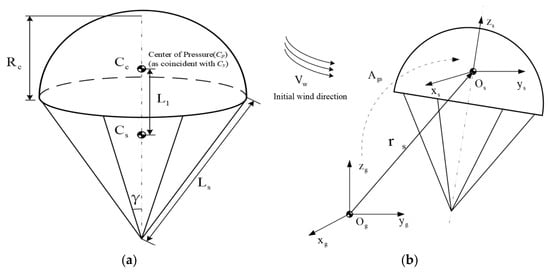
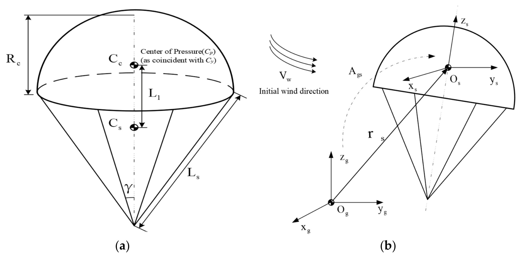
In this study, a hemispherical parachute is considered. To simplify the analysis and highlight the dominant dynamic characteristics during the steady-descent phase, the parachute canopy and connecting components are treated as an equivalent rigid body. The geometric configuration is illustrated in Figure 1a. Let Cc denote the centroid of the canopy and Cs denote the equivalent center of mass of the parachute. The canopy radius after full inflation is denoted by Rc, the distance between the canopy centroid and the equivalent center of mass of the parachute is denoted by L1, the suspension line length is denoted by Ls, and the suspension-line cone angle is denoted by γ. The masses of the canopy and suspension lines are denoted by mc and ms, respectively.
Figure 1.
Geometric parameters and coordinate system of the parachute. (a) Geometric parameters of the parachute. (b) Body-fixed coordinate system of the parachute.
The position vector of the parachute center of mass in the ground-fixed coordinate system is given by
where is the position vector from the origin of the ground-fixed coordinate system to the origin of the parachute body-fixed coordinate system, is the position vector of the parachute center of mass expressed in the parachute body-fixed coordinate system, and is the position vector of the center of mass in ground-fixed coordinate system. Asg is the transformation matrix between the parachute coordinate system and the ground coordinate system. By differentiating Equation (4) twice with respect to time, the absolute acceleration of a parachute mass point can be obtained.
According to Newton’s second law, the translational dynamic equation of the parachute can be written as
where Ms,eff is the effective translational inertia matrix of the parachute, and Fs represents the resultant external force acting on the parachute expressed in the ground-fixed inertial frame. It should be noted that the structural mass of the parachute is a scalar quantity, denoted by . The matrix form in Equation (5) is introduced only to account for the direction-dependent aerodynamic added-mass effect of the inflated canopy. Therefore, the effective translational inertia matrix can be written as
represents the added-mass matrix, which can be expressed as
Here, ms denotes the mass of the parachute, and max, may, and maz are the added masses of the parachute in the x-, y-, and z-directions, respectively. They can be expressed as
where kr is the reference coefficient of the radial added mass, ka is the reference coefficient of the axial added mass, and Vc is the inflated volume of the parachute canopy.
In Equation (5), can be expressed as
In the equation, Fxs, Fys, and Fzs represent the aerodynamic force components acting on the parachute in the three directions of the body coordinate system; Gs represents the gravitational force acting on the parachute, expressed in the ground-fixed inertial frame; T represents the tension force of the sling in the load coordinate system; and Apg is the transformation matrix between the payload coordinate system and the ground coordinate system.
The aerodynamic force acting on the parachute in the i-th direction can be described as
where ρ is the air density, Ci is the aerodynamic force coefficient in the corresponding direction, is a unified canopy reference area, and denotes the magnitude of the relative wind velocity at the parachute aerodynamic moment. The sign of the aerodynamic force is determined according to its direction relative to the flow velocity.
Because the parachute body-fixed coordinate system rotates with the parachute attitude, the time derivative of an arbitrary vector must satisfy the differentiation rule for rotating coordinate systems when transformed between the inertial frame and the body-fixed frame. For the position vector rs, its second derivative can be written as
where the subscript denotes differentiation in the inertial coordinate system, the subscript denotes differentiation in the parachute body-fixed coordinate system, and ωs is the angular velocity of the parachute body-fixed coordinate system relative to the ground-fixed inertial coordinate system.
Since the parachute canopy and connecting components are treated as an equivalent rigid body, the relative position of each mass point in the parachute body-fixed coordinate system remains unchanged. Therefore,
Consequently, Equation (11) can be simplified as
By combining Equations (4), (5), (9) and (13), the dynamic equation of the parachute in the ground-fixed coordinate system can be obtained as
To describe the attitude motion of the parachute during steady descent, the rotational dynamic equation is established in the parachute body-fixed coordinate system Osxsyszs. The rotational equation can be written as
In the formula, Hs represents the moment of momentum of the parachute around the center of pressure, and denotes the resultant external moment acting on the parachute.
where Js is the structural moment-of-inertia matrix of the parachute and Ja,s is the added moment-of-inertia matrix. Since the hemispherical parachute considered in this study is axisymmetric and the origin of the body-fixed coordinate system is located at the center of pressure, both Js and Ja,s can be approximately represented as diagonal matrices. The center of mass is determined by the mass distribution, whereas the center of pressure is determined by the pressure distribution. These two points do not generally coincide. For the steady-descent condition considered in this study, the center of pressure is approximated as coinciding with the center of mass by assuming an approximately axisymmetric pressure distribution.
The resultant external moment acting on the parachute consists of the aerodynamic moment and the moment induced by tether tension, namely,
Since the pressure center is set as the system origin, the influence of the aerodynamic moment can be ignored during the steady descent stage.
The moment generated by the tether tension is written as
where rT,s is the position vector of the tether attachment point relative to the center of pressure, and Ts is the tether tension acting on the parachute.
Substituting Equation (16) into Equation (15), the rotational dynamic equation of the parachute in the body-fixed coordinate system can be obtained as
2.3. Dynamic Model of the Payload
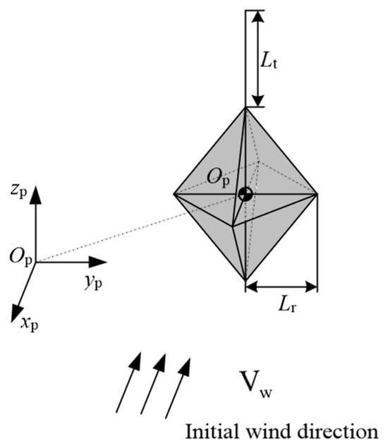
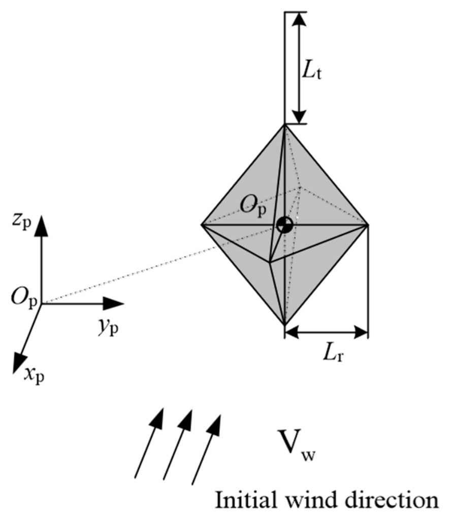
The payload considered in this study is a bipyramidal octahedral body. The tether and the bipyramidal octahedral payload are assumed to maintain a fixed relative configuration and are therefore modeled as a single equivalent rigid body. Under this assumption, the tether is considered to transmit both force and moment to the payload. A payload body-fixed coordinate system Opxpypzp is established with its origin located at the center of mass of the payload. The Opzp-axis is aligned with the tether direction and points upward, the Opxp-axis points in the direction of the initial incoming flow, and the Opyp-axis is determined according to the right-hand rule, as illustrated in Figure 2. The tether length, the length of the right-angle edge of the bipyramidal octahedron, the tether mass, and the payload mass are denoted by Lt, Lr, mt, and mp, respectively.
Figure 2.
Geometric parameters and body-fixed coordinate system of the payload.
In the ground-fixed inertial coordinate system, the translational dynamic equation of the payload can be expressed as
where rp is the position vector of the payload center of mass in the ground-fixed coordinate system, is the equivalent mass matrix of the payload, and Fp is the resultant external force acting on the payload system. The resultant external force consists of aerodynamic force, gravity, and tether tension, namely,
where Apg is the transformation matrix from the payload body-fixed frame to the ground coordinate system; Fxp, Fyp, and Fzp represent the aerodynamic force components of the load in the three directions of the body coordinate system, respectively; and Tp denotes the tether tension force acting on the payload. The aerodynamic force of the payload is the same as in Equation (10).
The rotational dynamic equation of the payload in the body-fixed coordinate system is written as
where ωp is the angular velocity vector of the payload, is the resultant external moment acting on the payload system, Jp is the structural moment-of-inertia matrix of the tether–payload system, and Ja,p is the added moment-of-inertia matrix of the payload.
The resultant external moment acting on the payload can be decomposed into the aerodynamic moment and the moment generated by tether tension:
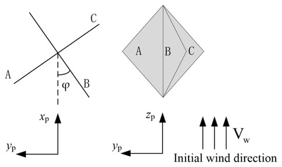
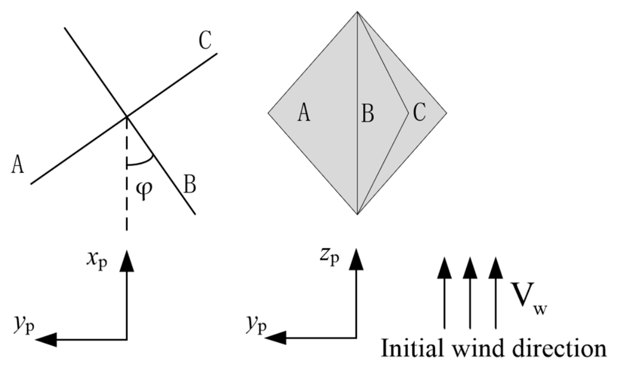
The tether-induced moment has the same form as Equation (19). For the bipyramidal octahedral payload, the aerodynamic moment mainly originates from the pressure drag acting on the windward facets. Owing to the geometric symmetry of the payload, the windward surface can be divided into three representative facets, denoted as facets A, B, and C, as shown in Figure 3.
Figure 3.
Schematic of the projected windward area of the payload.
Let φ denote the yaw angle of the payload relative to the incoming-flow direction. The aerodynamic force acting on a projected area element can be expressed as
where CD is the pressure-drag coefficient of the windward facet, Vrel is the relative incoming-flow velocity, and dA is the infinitesimal projected area element. For the aerodynamic drag coefficient of the load and the Reynolds number, they were mainly determined based on the research of Ahmad Sharifian [17].
The moment generated by this infinitesimal force element about the payload axis is given by
where y is the perpendicular distance from the infinitesimal element to the rotation axis. By integrating over the projected regions of the windward facets, the aerodynamic moments corresponding to facets A, B, and C can be obtained as MA, MB, and MC, respectively.
When the yaw angle satisfies 0 ≤ φ < π/4, the windward projection of the bipyramidal octahedron corresponds to the first type of geometric configuration. An analysis of the force conditions on facet B is conducted. Due to the symmetry, only the upper part of facet B needs to be analyzed. Combining Equations (24) and (25) yields
Here, represents wind speed and represents load speed. By the same reasoning, the force conditions on facets A and C can be derived as and .
By considering the torques exerted on the B face, A face, and C face, as well as the inclination angle of the double-angled octahedron, the total aerodynamic moment acting on the bipyramidal octahedral payload is obtained as
When the yaw angle satisfies π/4 ≤ β < π/2, the windward projection corresponds to another configuration. The calculation process is similar to the previous one. The total aerodynamic moment can be expressed as
Combining Equations (27) and (28), the total aerodynamic moment about the central axis of the payload can be expressed in a piecewise form as
For other values of β, the yaw angle can be mapped into the interval [0, π/2] according to the symmetry and periodicity of the bipyramidal octahedral geometry. Thus, the attitude response of the bipyramidal octahedral payload can be solved based on the above aerodynamic moment model. The proposed formulation is capable of reflecting the self-rotation, pendular motion, and attitude-coupled response of the complex-shaped payload under wind-induced aerodynamic moments.
Equations (20)–(29) constitute the rigid-body dynamic model of the bipyramidal octahedral payload. Compared with conventional models in which the payload is treated as a concentrated mass or a regular body, the present model explicitly accounts for the influence of the non-axisymmetric multi-faceted geometry on the aerodynamic moment, thereby improving the fidelity of attitude-motion prediction for parachute-suspended airborne corner reflectors.
2.4. Tether Tension Model
For the dynamic analysis of the parachute–payload system, separate body-fixed coordinate systems are defined for the parachute and payload, respectively. In the actual system, the parachute and the payload are connected through the tether. Therefore, the motion of the parachute and that of the payload are not independent but are coupled through geometric and dynamic constraints. In this section, the constraint relationship between the two subsystems is analyzed to determine the tether tension.
The tether attachment point is shared by both the parachute subsystem and the tether–payload subsystem. Therefore, the motion of this attachment point must be consistent when described from either subsystem. By analyzing the kinematics and dynamics of the tether attachment point, the constraint relationship between the parachute and payload can be established.
The translational and rotational equations governing the parachute and payload are given by Equations (9), (14), (20) and (21). Applying the kinematic compatibility condition at the tether attachment point yields the following constraint equation. By combining these equations, the parachute–payload system should satisfy the following constraint equation:
Therefore, the tether tension can be obtained by solving Equation (30). During the numerical simulations, the cable remained in a taut state, corresponding to the condition in Equation (30) where T ≥ 0. In this way, the dynamic constraint between the parachute subsystem and the bipyramidal octahedral payload subsystem is realized.
The tether tension model plays an essential role in the coupled dynamic analysis. On the one hand, the tether transmits the gravitational and aerodynamic loads between the parachute and the payload. On the other hand, it introduces additional constraint forces and moments, which directly affect the attitude evolution of both bodies. Compared with simplified models that assume a fixed or rigid connection, the present constraint-based treatment provides a more accurate description of the interaction mechanism between the parachute and the complex-shaped payload while retaining a relatively compact mathematical formulation.
Thus, by coupling the parachute dynamic model, the payload rigid-body dynamic model, and the tether tension model, a coupled dynamic model of the parachute-suspended bipyramidal octahedral payload system is established. This coupled model can be used to predict the descent trajectory, velocity variation, angular motion, and attitude response of the airborne corner reflector during the steady-descent phase.
3. Results
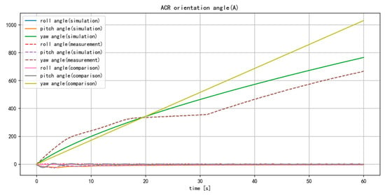
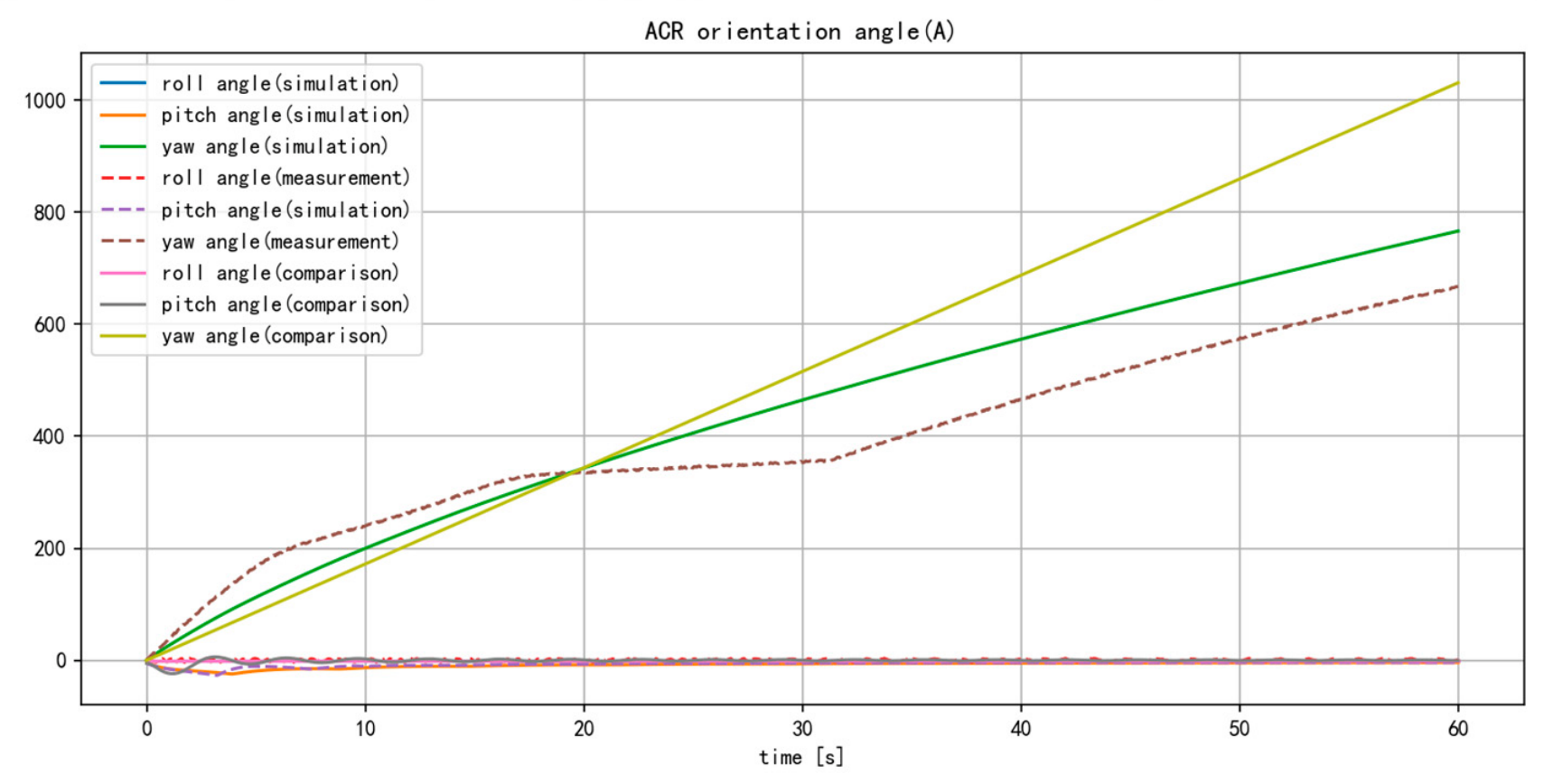
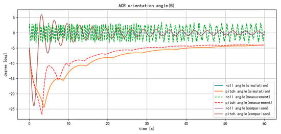
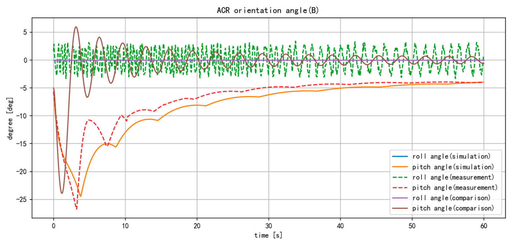
To validate the proposed model, the in-flight attitude motion of the bipyramidal octahedral payload was measured experimentally. A representative flight-test dataset with relatively small wind speed variation was selected for comparison. Meanwhile, a self-developed Python 3.10 program based on the fourth-order Runge–Kutta method was used to simulate the parachute–payload system. The main design parameters and initial attitude conditions in the simulation were kept consistent with those of the physical test. Furthermore, the proposed model was compared with the dynamic model reported in Ref. [3] which is the research most similar to the work presented in this paper. The measured and simulated results are compared in Figure 4 and Figure 5. Figure 4 presents the azimuth, pitch, and roll angles of the payload, while Figure 5 separately shows the pitch and roll angles because their amplitudes are much smaller than that of the yaw angle.
Figure 4.
Attitude variation in the payload, including azimuth, pitch, and roll angles.
Figure 5.
Attitude variation in the payload, including pitch and roll angles.
As shown in Figure 4 and Figure 5, the results obtained from the proposed model are generally closer to the measured data than those obtained from the comparison model, especially for the yaw and pitch angles. This agreement indicates that the proposed model improves the prediction of the attitude dynamics of the parachute-suspended payload. However, during the simulation process, the roll angles obtained by the proposed model and the comparison model were always zero values. As a result, the blue curve is completely overlapped by the pink curve in Figure 4 and Figure 5 and is therefore not visible. This discrepancy indicates that both models still have limitations in capturing the roll-angle response observed in the flight test. This might be due to minor changes in the wind field, local asymmetric flow, and limitations of the models.
To further analyze the performance of the model, we compared our model with the research content in the literature. Since neither the proposed model nor the comparison model was able to reproduce the roll-angle variation observed in the flight test, the comparative analysis was restricted to the simulated pitch- and yaw-angle responses. The root mean square error (RMSE), mean absolute error (MAE), and maximum absolute error were used as quantitative evaluation metrics, and the corresponding results are summarized in Table 1.
Table 1.
Comparison of model indicators.
As shown in Table 1, the proposed model achieves better performance than the comparison model for all evaluation metrics. This suggests that the proposed model allows it to more accurately capture the actual motion behavior of the parachute-payload system.
4. Discussion
4.1. Model Accuracy Analysis
In Figure 4, the dashed lines denote the measured data, and the solid lines denote the simulated results. The simulated and measured pitch angles exhibit similar trends during the first 18 s. From 18 s to 31 s, the simulated result varies faster than the measured one, whereas after 31 s, their variation rates become approximately consistent. As shown in Figure 5, the simulated pitch angle agrees reasonably well with the measured result, although the measured data show faster fluctuations and larger early-stage variations. The simulated roll angle remains close to zero, while the measured roll angle fluctuates slightly around zero.
Overall, the simulation results show good agreement with the field-test data. The pitch and yaw angles exhibit similar variation rates, and the roll-angle deviation remains small. The discrepancy in the yaw angle between 18 s and 31 s, as well as the deviations in the pitch and roll angles, can mainly be attributed to wind speed variations during the flight test. These results demonstrate that the proposed model can reliably predict the attitude response of the parachute-suspended bipyramidal octahedral payload.
4.2. Comparison with Classical Parachute–Payload Models
Our 11-DOF model bridges the gap between simplified low-fidelity models and computationally expensive high-fidelity frameworks. Unlike classic 2-DOF point-mass models, which neglect attitude and relative motion, our formulation explicitly resolves the rotational dynamics of both parachute and payload. Compared with 6-DOF rigid-body models, which often assume rigid parachute–payload connections, our constraint-based tether tension model avoids ad hoc spring–damper assumptions and yields physically consistent force transmission. Although models with more than 12 degrees of freedom can account for more realistic factors, such as flexible tethers, this is typically achieved at the cost of increased computational complexity, additional uncertain parameters, and more demanding parameter identification procedures. Our model achieves a favorable trade-off, retaining key physics (non-axisymmetric aerodynamics, geometric constraints) while maintaining real-time simulability (the total simulation time for 1000 time points using an i9 CPU is 2.55 s).
4.3. Applicability and Limitations of the Proposed Model
The proposed model is mainly applicable to the steady-descent phase of a parachute-suspended bipyramidal octahedral payload after canopy inflation. In this phase, the parachute canopy is assumed to be fully inflated and its large-scale deformation is neglected. The parachute canopy and the payload are both treated as rigid bodies, and the tether is modeled through a geometric constraint.
However, the present model has several limitations. First, the canopy inflation process and transient deployment dynamics are not considered. Second, canopy flexibility, fabric vibration, and suspension-line elasticity are neglected. Third, the aerodynamic coefficients are treated as prescribed parameters, and unsteady aerodynamic effects caused by turbulence, wake interference, and flow separation are not explicitly resolved. Fourth, the present validation is based on a limited number of flight-test records, and more tests under different wind conditions are required. Therefore, the model is most appropriate for preliminary trajectory prediction, attitude trend analysis, and engineering evaluation during the steady-descent phase, rather than for detailed deployment simulation or high-fidelity fluid–structure interaction analysis.
5. Conclusions
Based on the linear momentum theorem and angular momentum theorem, an improved dynamic model for a hemispherical parachute carrying a bipyramidal octahedral payload was established in this study. Separate body-fixed coordinate systems were introduced for the parachute and the payload, enabling independent descriptions of their translational motion, rotational motion, and attitude evolution. In addition, the tether tension and constraint relationship between the two subsystems were analyzed to characterize the dynamic coupling mechanism of the parachute–payload system.
Numerical simulations were performed for the steady-descent phase of the parachute–payload system. The results show that the yaw angular velocity of the payload decreases gradually from its initial value and tends toward a stable level, while the pitch angular velocity exhibits oscillatory convergence. The pitch angle also shows an initial rapid decrease followed by oscillatory recovery. Comparisons with field-test data indicate that the proposed model can reproduce the main dynamic characteristics of the actual system.
The proposed model maintains a relatively simple mathematical structure while accounting for the effects of parachute–payload coupling and complex payload geometry. Therefore, it provides a useful reference for the dynamic modeling, trajectory prediction, and attitude stability analysis of airborne corner reflectors and other parachute-suspended non-axisymmetric payloads.
Future work may focus on incorporating unsteady aerodynamic effects, wind disturbance, flexible tether dynamics, and more detailed aerodynamic coefficients obtained from computational fluid dynamics or wind tunnel tests, so as to further improve the prediction accuracy of the model under complex flight conditions.
Author Contributions
Conceptualization, S.H. methodology, J.W.; validation, J.X.; formal analysis, S.H.; data curation, J.X.; writing—original draft preparation, J.W.; writing—review and editing, J.X.; All authors have read and agreed to the published version of the manuscript.
Funding
This research received no external funding.
Data Availability Statement
Due to internal laboratory regulations, detailed data cannot be directly disclosed.
Conflicts of Interest
The authors declare no conflicts of interest.
References
- Luo, Y.; Guo, L.; Zuo, Y.; Liu, W. Time-Domain Scattering Characteristics and Jamming Effectiveness in Corner Reflectors. IEEE Access 2021, 9, 15696–15707. [Google Scholar] [CrossRef] [Scilit]
- Qiu, M.; Ai, X.; Xu, Z.; Zhao, F. Comparative Analysis of Monostatic and Bistatic RCS Scattering Characteristics for Corner Reflector. In Proceedings of the 2022 International Applied Computational Electromagnetics Society Symposium (ACES-China), 9–12 December 2022; IEEE: Piscataway, NJ, USA, 2022; pp. 1–3. [Google Scholar]
- Wu, L.; Hu, S.; Xu, J.; Liu, Z. Dynamic sequential radar cross section properties of airborne corner reflector in array. IET Radar Sonar Navig. 2023, 17, 1405–1419. [Google Scholar] [CrossRef] [Scilit]
- Wu, L.; Hu, S.; Feng, C.; Luo, Y.; Liu, Z.; Lin, L. Dynamic Doppler characteristics of maritime airborne corner reflector. J. Mar. Sci. Eng. 2024, 12, 727. [Google Scholar] [CrossRef] [Scilit]
- Zhang, J.; Hu, S.; Yang, Q.; Fan, X. RCS statistical features and recognition model of air-floating corner reflector. Syst. Eng. Electron. 2019, 41, 780–786. [Google Scholar]
- Guglieri, G. Parachute-Payload System Flight Dynamics and Trajectory Simulation. Int. J. Aerosp. Eng. 2012, 2012, 182907. [Google Scholar] [CrossRef] [Scilit]
- White, F.M.; Wolf, D.F. A theory of three-dimensional parachute dynamic stability. J. Aircr. 1968, 5, 86–92. [Google Scholar] [CrossRef] [Scilit] [PubMed]
- Wolf, D. Dynamic stability of a nonrigid parachute and payload system. J. Aircr. 1971, 8, 603–609. [Google Scholar] [CrossRef] [Scilit]
- Tory, C.; Ayres, R. Computer model of a fully-deployed parachute. J. Aircr. 1977, 14, 675–679. [Google Scholar] [CrossRef] [Scilit]
- Doherr, K.-F.; Schilling, H. Nine-degree-of-freedom simulation of rotating parachute systems. J. Aircr. 1992, 29, 774–781. [Google Scholar] [CrossRef] [Scilit]
- Talay, T.A. Parachute-Deployment-Parameter Identification Based on an Analytical Simulation of Viking BLDT AV-4; No. NASA-TN-D-7678; National Aeronautics and Space Administration (NASA): Washington, DC, USA, 1974.
- Pillasch, D.; Shen, Y.; Valero, N. Parachute/submunition system coupled dynamics. In Proceedings of the 8th Aerodynamic Decelerator and Balloon Technology Conference; AIAA: New York, NY, USA, 1984; p. 784. [Google Scholar]
- Nikravesh, P.E. Dynamic analysis of large-scale mechanical systems and animated graphics. J. Guid. Control Dyn. 1985, 8, 104–109. [Google Scholar] [CrossRef] [Scilit] [PubMed]
- Shuwei, G.; Yangbiao, D.; Zizeng, Q. Dynamic model and discussion of the parachute and payload system. Spacecr. Recovery Remote Sens. 2008, 29, 38–44. [Google Scholar]
- Iyer, P.G. Modelling of a 12-DoF Parachute–Riser–Payload system dynamics using Kane’s method. Multibody Syst. Dyn. 2024, 60, 599–619. [Google Scholar] [CrossRef] [Scilit]
- Zhu, H.; Sun, Q.; Tao, J.; Tan, P.; Chen, Z.; Dehmer, M.; Xie, G. Fluid-Structure Interaction Simulation and Accurate Dynamic Modeling of Parachute Warhead System Based on Impact Point Prediction. IEEE Access 2021, 9, 104418–104428. [Google Scholar] [CrossRef] [Scilit]
- Sharifian, A.; Buttsworth, D.R. Computational Simulation of the Wind-force on Metal Meshes. In Proceedings of the 16th Australasian Fluid Mechanics Conference; The University of Queensland Press: Brisbane, QLD, Australia, 2007; pp. 766–770. [Google Scholar]

Disclaimer/Publisher’s Note: The statements, opinions and data contained in all publications are solely those of the individual author(s) and contributor(s) and not of MDPI and/or the editor(s). MDPI and/or the editor(s) disclaim responsibility for any injury to people or property resulting from any ideas, methods, instructions or products referred to in the content. |
© 2026 by the authors. Licensee MDPI, Basel, Switzerland. This article is an open access article distributed under the terms and conditions of the Creative Commons Attribution (CC BY) license.