


Abstract
This research focuses on a cooperative guidance scenario involving multiple unmanned aerial vehicles (UAVs). The objective is to achieve a simultaneous interception of a maneuvering target while maintaining strict constraints on the relative geometry. To tackle this challenge, we introduce a distributed optimal spatial–temporal cooperative pursuit strategy. Initially, the impact angles and interception times for each UAV are analytically predicted based on the augmented ideal proportional navigation (AIPN) guidance scheme. Subsequently, we employ an optimal distributed consensus protocol to synchronize the UAVs, ensuring they converge on the target at the same time while preserving a predetermined intercept geometry. The proposed method offers significant advantages in a distributed framework, notably reducing control energy consumption by approximately 63.0% compared to an existing state-of-the-art cooperative guidance law. Comprehensive simulations are conducted to validate the energy efficiency of the approach.
1. Introduction
In recent years, distributed cooperative UAV guidance has received much attention due to its low communication requirement. And the spatial–temporal cooperative guidance scheme has stood out for its capability of enhancing interception performance.
Existing distributed cooperative guidance methods primarily employ multi-agent consensus theory [1,2], achieving cooperation by controlling the convergence of state errors among neighboring vehicles in communication. For instance, in [3], the authors proposed a distributed cooperative guidance law for single-integrator systems based on linear consensus dynamics, enabling a simultaneous impact on the target by multiple vehicles. In [4], target-missile engagement kinematics were formulated as a double-integrator system, and a salvo attack guidance method was designed using a linear consensus protocol that does not require time-to-go estimation. Then, the authors of [5] proposed a cooperative guidance system that avoids terminal numerical singularities. Distributed cooperative guidance methods that incorporate field-of-view constraints by combining linear consensus protocol with saturation functions have also been studied in [6,7,8]. However, linear consensus algorithms can only guarantee asymptotic convergence, and the presence of disagreement residuals may lead to non-consensus states.
To achieve consensus in finite time, the consensus protocols with strict convergence properties have been investigated in [9,10,11,12,13,14,15] by leveraging nonlinear control philosophy. However, the convergence time and guidance parameters for these finite-time methods are typically dependent on initial conditions, bringing about complex parameter adjustment when the scenario changes. This prohibits their practical implementation [16,17]. To mitigate this issue, the fixed and prescribed convergence methods have been studied and implemented with cooperative guidance design [18,19,20,21]. However, these nonlinear methods primarily focus on convergence properties while lacking physically significant performance indices, potentially resulting in unnecessary energy consumption [22].
Moreover, the existing spatial–temporal cooperative guidance approaches are generally designed by combining terminal angle-constrained guidance laws with finite or fixed-time consensus approaches [18,23,24]. But these spatial–temporal cooperative methods utilize predefined absolute impact angles rather than dynamic relative ones. And the authors of [25,26] pointed out that, for spatial cooperation, imposing relative geometry will consume less energy and bring about a more tractable guidance problem than preassigned impact angles. The reason for this phenomenon is that relative constraints are much looser than absolute ones. Hence, imposing relative impact geometry is a more feasible approach when designing spatial–temporal cooperative guidance for encirclement attack. More recently, the authors of [27] proposed a bipartite consensus control framework for heterogeneous unmanned systems subject to communication failures, advancing the robustness of cooperative guidance in complex network environments.
Motivated by the preceding observation, this paper aims to propose a distributed optimal spatial–temporal cooperative guidance for simultaneous interception with relative impact geometry. Based on augmented ideal proportional navigation (AIPN) guidance, the relative impact times and angles are first predicted, and their dynamics are formulated into a high-dimensional first-order dynamic system. By constraining the relative impact times and angles, the optimal solution for minimizing general energy cost is derived by sequentially leveraging optimal control theory and a parameter optimization approach. The main contribution of this paper is twofold:
- 1.
- An optimal terminal consensus protocol is proposed to solve a distributed cooperative guidance problem. Since the proposed protocol minimizes the performance index associated with energy consumption, it is believed to consume less effort than existing consensus-based approaches.
- 2.
- The proposed two-dimensional and three-dimensional spatial–temporal cooperative law constrains the relative interception geometry rather than absolute angles, which will be more feasible and energy-efficient.
The remainder of this paper is organized as follows. Section 2 introduces the mathematical model and formulates the guidance problem. Section 3 presents the details of the proposed approach, followed by its extension in three-dimensional space in Section 4. Finally, some simulation results and discussions are presented in Section 5 and conclusions are drawn in Section 6.
2. Problem Formulation and Preliminaries
2.1. Problem Formulation
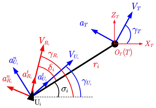
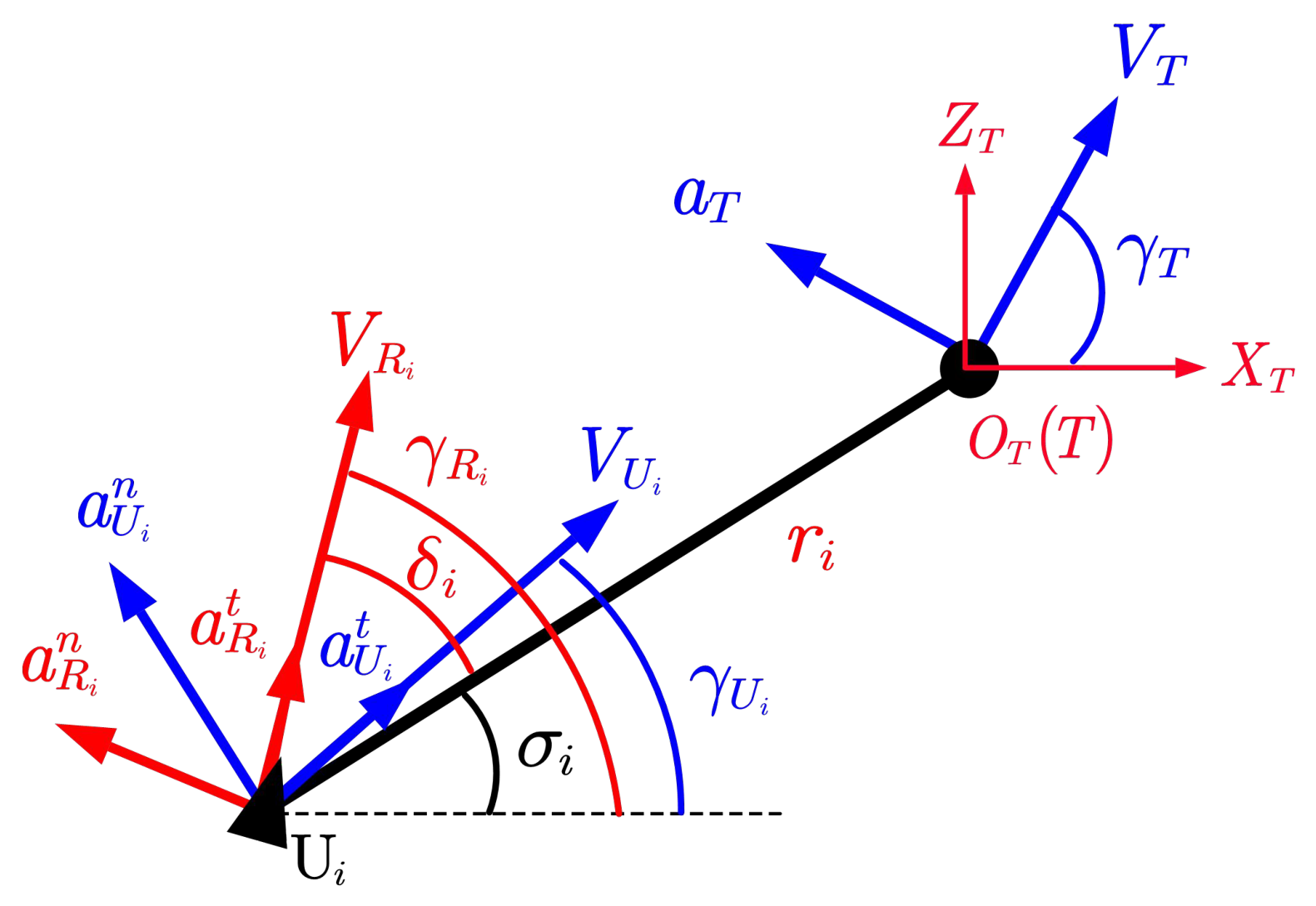
This paper addresses the guidance issue of multiple UAVs collaboratively attacking one intrusive target. The kinematics model is established in the coordinate system with its origin on the target, as depicted in Figure 1. The ith pursuer and the target in Figure 1 are denoted by and T, respectively. The symbol stands for the relative range between the ith pursuer and the target. The symbols V and a represent the velocity and acceleration of vehicles, with subscripts , T, and representing the pursuer, the target, and their relative motion, respectively. The symbol of and denote the relative flight path angle and the LOS angle, respectively.
Figure 1.
Engagement geometry in relative frame.
Accordingly, the relative kinematics can be formulated as
where
In the above equation, and represent the pursuer’s and target’s acceleration components perpendicular to the direction of relative velocity, respectively.
To cooperatively pursue the target with specified intercept geometry, the constraints of interception, spatial cooperative, and temporal cooperative are, respectively, formulated as
where and denote the ith final LOS angle and impact time, respectively. The notation represents the terminal LOS angle deviation between the ith pursuer and other pursuers, forming a desired spatial intercept geometry against the maneuvering target.
Note that the individual interception constraint (7) can be achieved by utilizing AIPN guidance law as [28,29]
2.2. Communication Topology Based on Graph Theory
Considering the practical requirement of reducing communication burdens among interception collaborators, a distributed cooperation is considered in this paper. As prerequisite knowledge, the graph-based communication topology theory is introduced in this subsection.
Define as a graph characterizing the information communication among multiple pursuers. The symbol of denotes a set of nodes that represents n pursuers. The set comprises connectivity edges between the two nodes that have information dissemination, which is quantified by the adjacency matrix . Specifically, of a directed graph indicates that the ith pursuer has access to the information from neighbor j and otherwise, whereas in an undirected graph, implies the pursuers i and j aree information-sharing. Moreover, the degree matrix associated with is defined as a diagonal matrix with element , and the Laplacian matrix is accordingly determined by for and . In the following, the communication graph is assumed to be undirected and connected, which implies that the adjacency matrix and the Laplacian matrix are symmetric. Under this assumption, and are specified as symmetric matrices.
3. Distributed Spatial–Temporal Cooperative Guidance
3.1. Design of Proposed Method
This section aims to develop a distributed guidance method to satisfy the spatial and temporal cooperative constraints based on the prediction-correction concept.
According to the AIPN law (10), the terminal LOS angle can be predicted as [30]
indicating that the convergence of is associated with , whose kinetics are determined by the normal acceleration , as shown in Equation (3). Thus, the spatial cooperative pursuit constraint (8) can be ensured by regulating . Redefine the normal guidance command as
where ensures the perfect interception while is the bias term to regulate the terminal LOS angle. Then, the kinetics of can be obtained by differentiating (11) and substituting Equation (12)
Regarding the temporal cooperative pursuit constraint (9), the impact time can be described as
Assuming the relative lead angle is a small angle, the time-to-go can be accordingly predicted as
By differentiating Equation (14) and combining it with , we get
where represents the ith closing acceleration along its LOS direction. Equation (16) reveals that, by designing a suitable closing acceleration , the guidance time of each pursuer can be adjusted, thereby achieving the temporal cooperative interception.
Remark 1.
It is well known that the exact time-to-go depends on the relative range, the closing speed, and the lead angle. Under the commonly adopted small-angle assumption, i.e., when the relative lead angle remains small throughout the engagement, the time-to-go can be accurately approximated by [18,20]. In many homing engagement scenarios, especially when the pursuer is initially aligned near the collision course or when the line-of-sight rate is well regulated, this approximation holds reasonably well. Even when moderate lead angles appear at the beginning of the engagement, the guidance system will drive the lead angle gradually toward zero to achieve interception. Consequently, the small-angle assumption is satisfied in the mid-to-terminal phase, where the approximation error becomes negligible.
From Equations (13) and (16), it can be observed that the spatial–temporal cooperative pursuit problem studied in this paper can be transformed into the dynamics regulation issue of and , which is separately dominated by the normal acceleration and closing acceleration. Thus, we define a state vector as
where and denote the LOS angle and impact time state vectors, respectively. Then, Equations (13) and (16) can be integrated into a compact state-space matrix
where
Accordingly, the spatial–temporal cooperative constraint vector (8) and (9) for all distributed pursuers yields
where is the terminal state of . And is the state derivation vector among each pursuer. Specifically, denotes the impact-angle difference vector between connected pursuers, which is determined by the LOS angle deviation of each missile. denotes the impact-time difference vector between connected pursuers, which is explicitly set to zero to enforce the simultaneous interception condition. The notation of indicates the communication relationship between every two pursuers.
Subsequently, to satisfy the dynamics (18) with its terminal constraint (21), this paper proposes an optimal high-dimensional consensus problem
where
The notations and represent the guidance parameters for spatial and temporal cooperation, respectively.
Lemma 1 presents the globally optimal solution to the centralized optimal control problem (22) when the communication topology is fully connected (i.e., when the Laplacian matrix has full rank and all agents share information with each other).
Lemma 1.
When the UAVs mutually connect in a centralized topology, the optimal solution for problem (22) is [31]
where denotes the Moore–Penrose inverse matrix of the Laplacian matrix . And .
Proof.
The proof is given by utilizing the Hamiltonian matrix method [31]. □
However, when the UAV swarm communicates only via a distributed (sparse) topology, the fully connected assumption does not hold, and the globally optimal solution in Lemma 1 is no longer directly applicable because each agent only has access to its neighbors’ information. To overcome this limitation, we propose a feasible region-parameter-optimization approach that approximates the globally optimal solution with a distributed implementation.
Lemma 2.
When the UAVs connect with each other in a distributed topology, the dynamics and constraints in Equation (22) can be achieved when the command satisfies
where is a diagonal matrix whose i-th diagonal entry is , and is the diagonal element of the Moore–Penrose inverse matrix .
Proof.
It is known that , where and denote the n-dimensional identity matrix and the all-ones matrix, respectively. Therefore, left-multiplying by the matrix in Equation (24) causes to violate the condition that elements corresponding to non-existent connections should be zero, implying that the optimal solution requires global information of the entire swarm system.
Hence, to best satisfy the performance index in (24) under distributed communication constraints, it is necessary to find a matrix that respects the properties of the Laplacian matrix and minimizes the Euclidean distance from , i.e.,
where , and the vector consists of the i-th row of . The above property implies that the zero-element positions in the rows of are identical to those in the rows of , which requires that each row vector of be a scaled version of the corresponding row vector of element-wise. It follows that has exactly one non-zero element, namely , where . Consequently, the expression of is obtained as
where , and is an arbitrary non-zero scalar.
Substituting (27) into the Euclidean norm in (26) yields
where are the elements of the Laplacian pseudo-inverse matrix . The above expression is a typical convex function, so its extremum can be obtained by solving , which gives
where . Accordingly, substituting and Equation (29) into Equation (24) yields the locally optimal control input in Equation (25). □
This law is a locally implementable suboptimal solution that approximates the globally optimal one by modifying the pseudo-inverse of the Laplacian to fit the distributed information structure. Importantly, it preserves the terminal feasibility under the same constraint because the row sum of remains consistent with the centralized case. Thus, the relation between Lemma 1 and Lemma 2 is that Lemma 2 provides a practical distributed approximation of the global optimum. It is not globally optimal due to limited communication, but it is designed to be locally optimal in the sense that each agent minimizes its own cost using only neighbor information while ensuring the terminal coordination constraint.
As a result, by combining Equations (20) and (12), the normal and closing guidance commands can be readily derived as
Note that UAV autopilots generally operate in their respective velocity coordinate systems. Hence, the normal and tangential acceleration commands for spatial–temporal cooperative pursuit are given as
3.2. Convergence Analysis of Proposed Method
This subsection aims to analyze the convergence of the cooperative consensus among pursuers. Combining Equation (18) with (25), the distributed locally optimal consensus dynamics can be derived as
Notably, following [1], we can obtain , where represents the terminal consensus state and is the disagreement vector. This implies that analyzing the dynamics of directly yields the consensus convergence performance.
Differentiating both sides of and combining the result with Equation (34) yields
To prove the convergence of , we choose the Lyapunov function as
Since the positive definite matrix ensures for any , the Lyapunov function in (36) is positive definite.
Next, we further prove the negative definiteness of the first derivative of the Lyapunov function. Replace the variable t in (36) with . Correspondingly, the domain of the independent variable changes from to . Differentiating both sides of Equation (36) with respect to and incorporating Equation (35) with the expression of , we can get
Observing the form of in Equation (29), the second term in (29) becomes zero after right-multiplying by . Therefore, combining Equation (25) and (37) yields
Since the Laplacian pseudo-inverse is a diagonally dominant matrix with positive diagonal entries , it follows that is positive definite. Moreover, because is a diagonal matrix, we have and consequently . Hence, as (i.e., ), we have , which implies that as . The above proof shows that under the proposed distributed locally optimal consensus dynamics, the cooperative state of multiple pursuers can achieve the desired consensus.
4. Design of Three-Dimensional Distributed Cooperative Guidance
Since both pursuers and the target move in three-dimensional space in practical applications, this section extends the cooperative guidance law designed in Section 3 to three-dimensional space to provide guidance for engineering implementation.
The two-dimensional multi-directional encirclement-constrained cooperative guidance command can be decomposed into a pointing-error-elimination term and an encirclement-angle-constraint term. The expression of the heading error elimination term in three-dimensional space can be expanded as
where and denote the yaw line-of-sight (LOS) angle and the pitch LOS angle, respectively, and and are the corresponding LOS angular rates.
Due to the influence of distributed communication, the encirclement angle constraint command term (30) of each pursuer is coupled with the states of its neighboring pursuers. Therefore, we first derive the encirclement angle constraint commands for the longitudinal and lateral channels in matrix form in a relative coordinate system and then transform each pursuer’s command into its velocity coordinate system. The encirclement angle constraint commands for the longitudinal and lateral channels are, respectively, given by
Here, is the terminal pitch LOS angle state vector, and is the corresponding desired terminal pitch LOS angle error vector. is the terminal yaw LOS angle state vector, and is the corresponding desired terminal yaw LOS angle error vector. Equations (40) and (41) achieve the elimination of relative pitch and yaw LOS angles between adjacent pursuers, respectively. Similar to the two-dimensional form (30), the guidance parameter ensures strict convergence of the encirclement angle deviation. Moreover, when , where can be determined in advance from the communication topology of the pursuer swarm, the smooth convergence of the control commands (40) and (41) is guaranteed.
From Equations (39) to (41), the lateral and normal acceleration commands for each pursuer in the relative velocity coordinate system are obtained as
Furthermore, the projection of the target acceleration onto the pursuer’s velocity coordinate system is given by
where and are rotation matrices. The definitions of the pursuer’s flight path angle and inclination , as well as the target’s flight path angle and inclination , are computed as
Based on the transformations between the relative velocity coordinate system, the inertial coordinate system, and the pursuer’s velocity coordinate system, the lateral acceleration and normal acceleration commands for the pursuer are derived as
where the relative velocity angle and inclination are respectively expressed as
Equation (45) yields the three-dimensional multi-directional encirclement cooperative guidance command. To simultaneously form the encirclement geometry, the terminal guidance times of the pursuer swarm must also be synchronized, which is achieved by using command (31). Since this command adjusts the guidance time by varying the pursuer’s speed and acts along the LOS direction, the time-cooperative control command for each pursuer in three-dimensional space is derived from the relationship between the LOS coordinate system and the pursuer’s velocity coordinate system as
where is the command for the i-th pursuer from Equation (31), and the definitions of the pitch LOS angle , yaw LOS angle , pursuer flight path, inclination and flight path angle are given.
5. Simulation Results
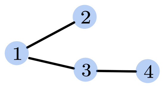
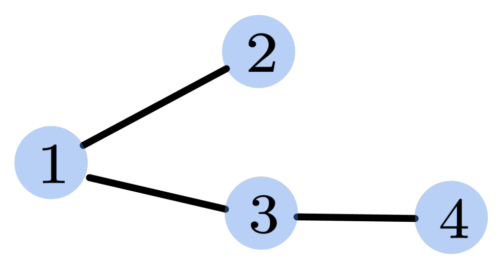
This section demonstrates the feasibility and properties of the proposed method and compares the proposed approach with the distributed cooperative guidance in [18]. Four pursuers cooperate to intercept a target. The distributed communication topology among pursuers is shown in Figure 2.
Figure 2.
Communication topology among pursuers.
The corresponding Laplacian matrix can be expressed as
According to the definition of Equation (25), the locally optimal pseudo-inverse matrix expression of Laplacian matrix can be obtained. The guidance parameters are selected as and to ensure the convergence of spatial and temporal cooperative constraints. Additionally, two adjacent pursuers are set to intercept the target at the same time as the specified geometry with a line-of-sight (LOS) angle interval of 20°. Hence, the expected terminal LOS angle and guidance time deviation vector are respectively set as
To facilitate the analysis of state consensus convergence, the state deviation of each pursuer from all other adjacent pursuer is defined as
where is composed of the LOS angle difference and the impact-time difference .
5.1. Performance of Proposed Method in Two-Dimensional Space
This subsection presents the feasibility of the proposed distributed cooperative guidance approach in two-dimensional space, where four pursuers collaboratively intercept a single maneuvering target. The initial conditions of the pursuers and the target are shown in Table 1.
Table 1.
Initial conditions of simulation.
The target speed remains constant, while its lateral acceleration is expressed as
where and represent the acceleration components in the target velocity reference frame, respectively, with the unit m/s2.
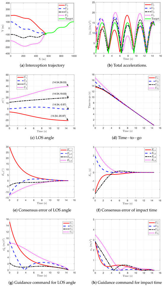
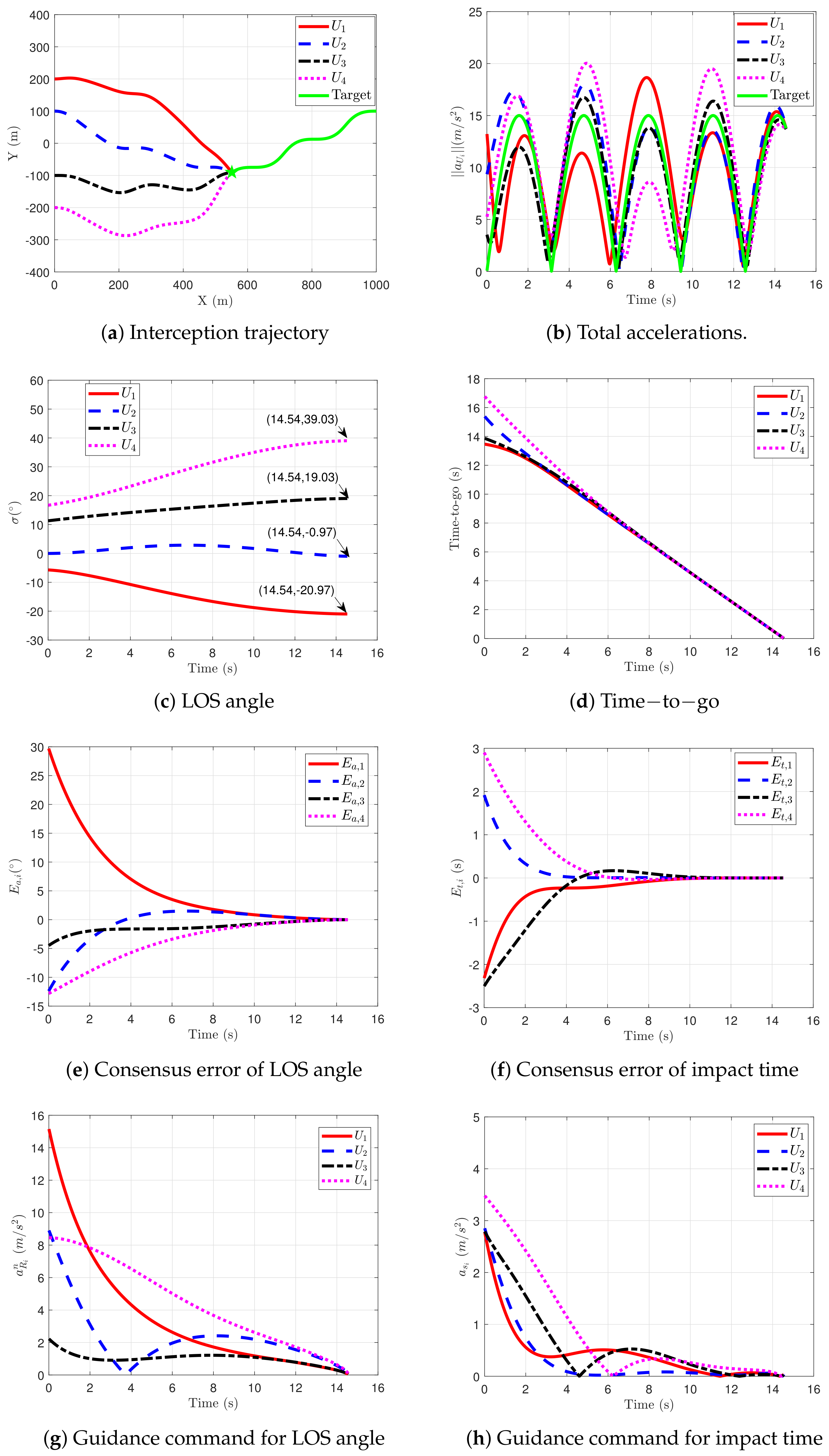
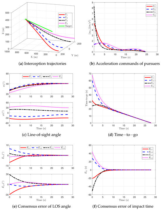
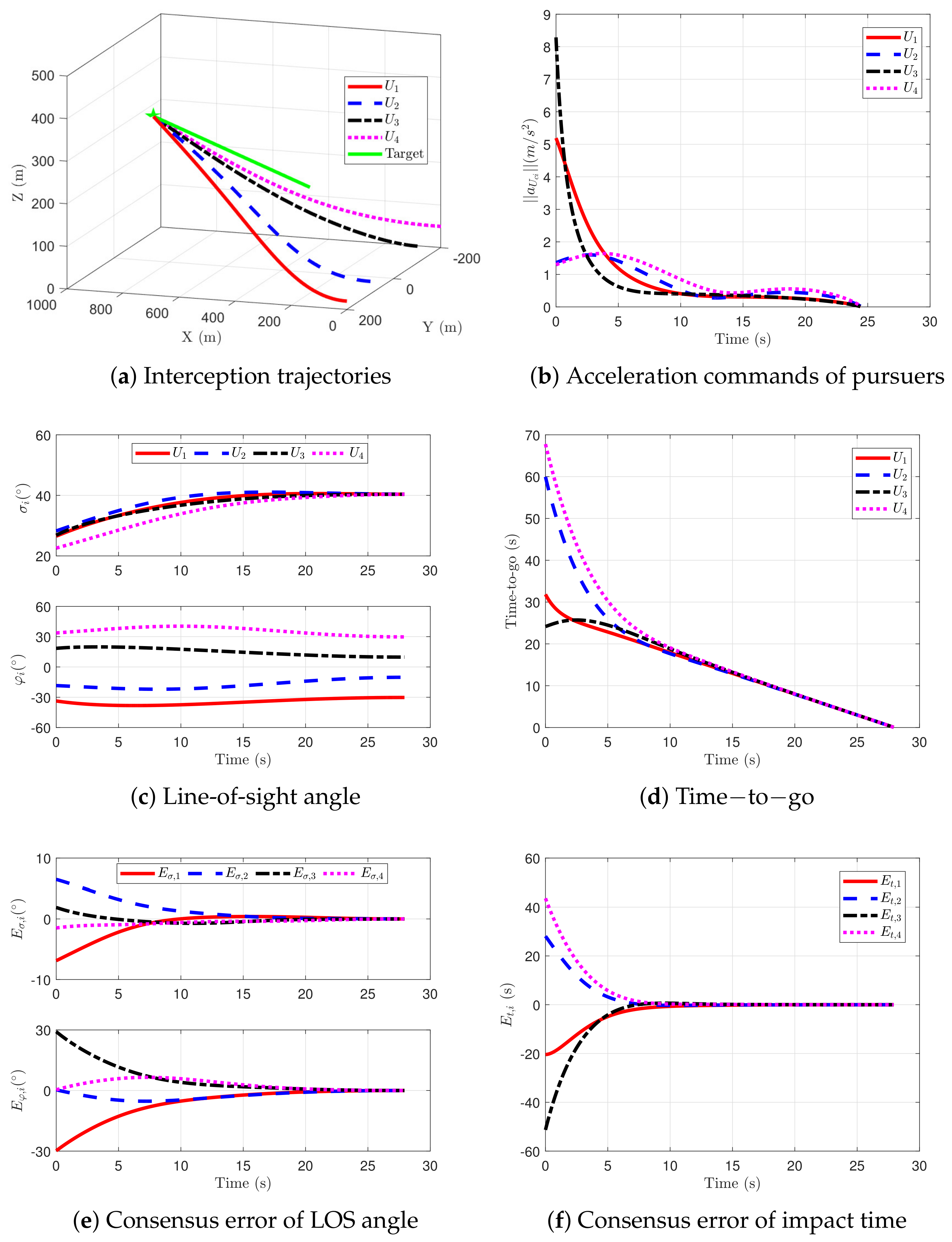
The simulation results are depicted in Figure 3. It can be observed that four pursuers finally form an encirclement geometry to intercept the maneuvering target. Furthermore, Figure 3c shows that the final relative LOS angle error of two adjacent pursuers meets the set value of 20°. Therefore, the consensus error of the LOS angle in Figure 3e converges to 0 at the end. In addition, decreases exponentially to 0, which conforms to the convergence of distributed consistency error in [31]. Figure 3d,f shows the impact time of each pursuer and its consistency error. It can be seen that the impact time of each pursuer also gradually converges and conforms to the constraint of simultaneously intercepting targets.
Figure 3.
Simulation results of the proposed method.
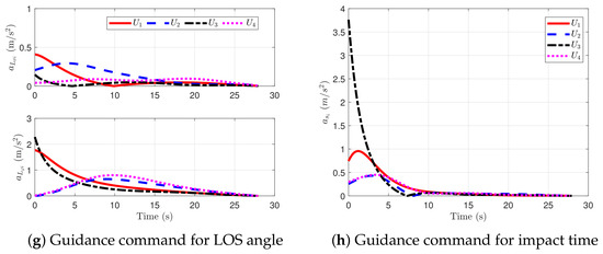
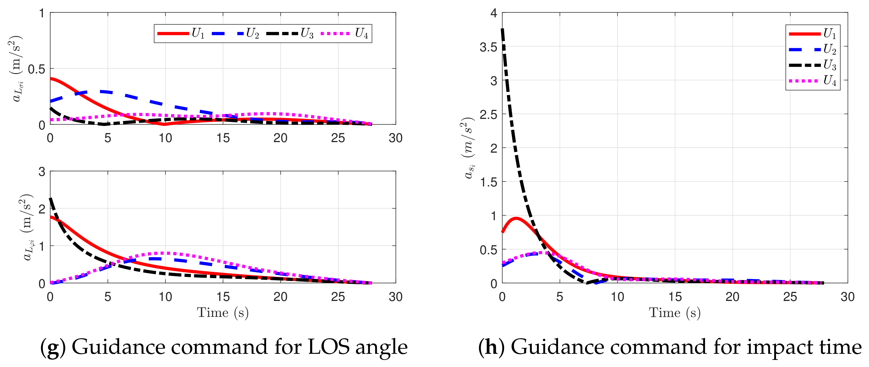
From Figure 3g,h, we can find that the acceleration commands for controlling LOS angle and impact time, i.e., and , converge to 0. And the acceleration command amplitude of each pursuer in the Figure 3b is equal to the target acceleration at the end. This phenomenon can be explained in combination with the expressions (32) and (33). Specifically, when and become 0, the pursuer’s normal acceleration and tangential acceleration command converge to the normal and tangential components of the target acceleration, respectively. Thus, the total acceleration of the pursuer is equal to the target acceleration, as shown in Figure 3b. This characteristic can help to reserve sufficient maneuvering margin to resist the disturbance and quickly restore the UAV’s consistency and cooperative state. As a result, the proposed guidance method has a feasible spatial–temporal cooperative interception effect under a distributed connecting topology.
5.2. Comparative Simulation
This subsection simulates the approach in [18] under the identical condition in Table 1 for comparison. In this case, the guidance gains of the proposed law are selected as , and the parameters of the comparative method are selected to be the same as those in [18]. Since the desired LOS angles in [18] are preset manually rather than being automatically adjusted based on the desired terminal angular difference between the pursuers, the desired LOS angles obtained via the proposed method are adopted in its implementation for a fair comparison. Specifically, the desired angles are set to .
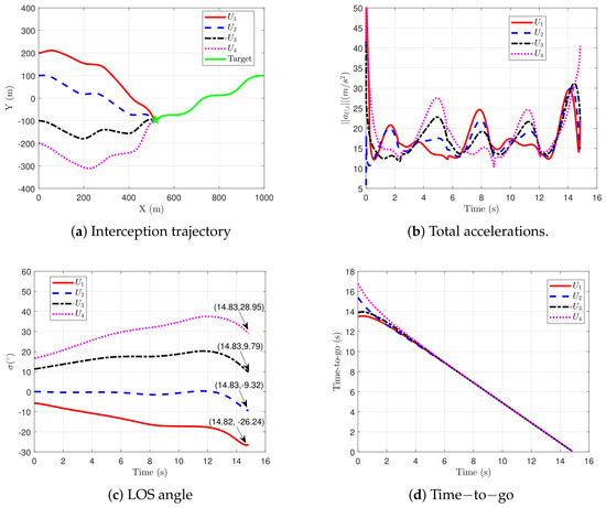
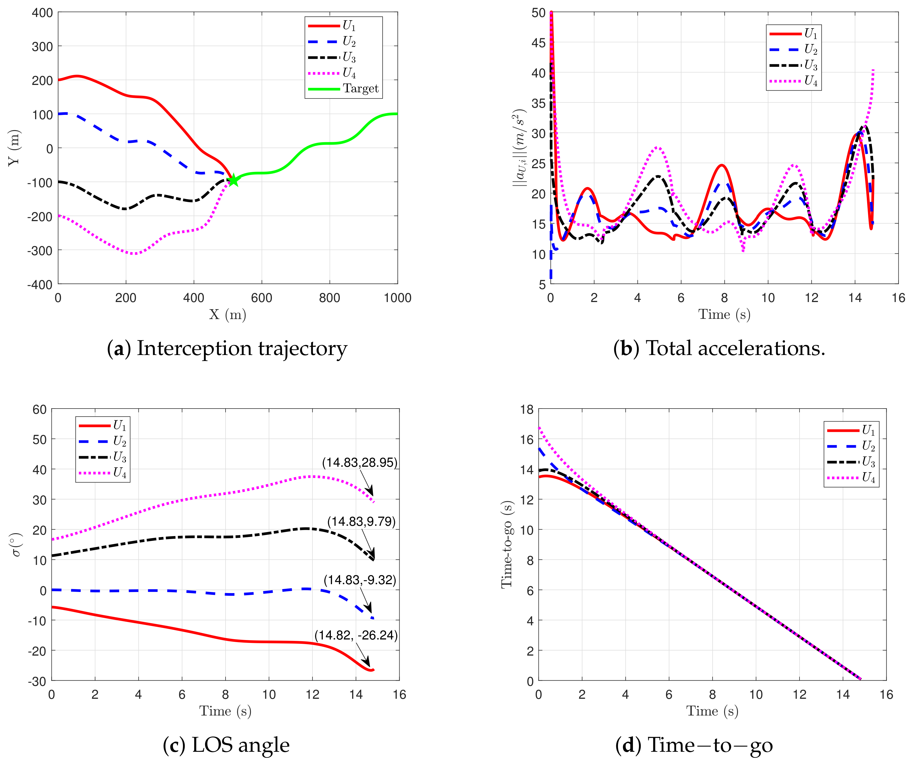
The simulation results of the approach proposed in [18] are depicted in Figure 4. The simulation results in Figure 4 demonstrate that, although the distributed guidance law in [18] enables spatial–temporal cooperative interception, its command magnitudes are higher than those in Figure 3. Furthermore, in the method of [18], the terminal angle briefly converges near but subsequently diverges, rather than converging to the desired value at the final stage of guidance. This behavior compromises the relative angle control requirement for cooperative guidance of multiple UAVs. In contrast, the proposed method strictly meets the requirement that the relative terminal angle between two adjacent UAVs is , demonstrating superior collaborative interception performance.
Figure 4.
Trajectories and accelerations of method [18].
For a thorough evaluation of interception performance, a cost function is introduced:
which quantifies the total control energy consumed by each pursuer during the engagement. The energy comparison results are listed in Table 2. It can be observed that the method in [18] has significantly larger control expenditure than the proposed approach. Quantitatively, the total control effort is reduced from 10.07 to 3.72, i.e., a reduction of approximately 63.0%, confirming the superior energy efficiency of the proposed guidance law. As a result, the proposed method is proven to be feasible and more energy-efficient.
Table 2.
Total control effort (103 m2/s3).
5.3. Validation of Three Distributed Cooperative Guidance
This section verifies the feasibility of extending the distributed optimal cooperative guidance law to three-dimensional space. The three-dimensional cooperative guidance command for the interceptors is given by Equations (45) and (47).
The simulation scenario in this subsection considers four pursuers cooperating in a tail-chase engagement against a constant-velocity target. The communication topology among the interceptors is shown in Figure 2. The initial conditions for pursuers and the target are provided in Table 3. The desired encirclement formation at the terminal time is specified such that the relative yaw LOS angle between any two communication-adjacent interceptors is , while the relative pitch LOS angle is . The control parameters for pitch and yaw LOS angle consensus are set to , and the parameter for guidance time consensus is .
Table 3.
Initial conditions for 3-D cooperative guidance.
The simulation results of the proposed method in three-dimensional space for intercepting a maneuvering target are shown in Figure 5. From Figure 5d,f, it can be seen that the remaining guidance times of the four interceptors become consistent at the terminal moment, and the time consensus error converges to zero exponentially, i.e., simultaneous interception of the target is achieved. Moreover, in Figure 5c, the four pitch LOS angles eventually converge to zero, while the yaw LOS angles converge to a separation. Correspondingly, the pitch and yaw LOS angle consensus errors in Figure 5e both decay to zero at the terminal time, satisfying the desired encirclement formation constraint. Since both the guidance time and the LOS angles achieve consensus, the corresponding control commands also converge to zero at the terminal moment. Consequently, the interceptor accelerations converge to the magnitude of the target acceleration, i.e., decay to zero, as shown in Figure 5b, which helps reduce the risk of guidance accuracy degradation due to acceleration saturation at the terminal phase. Comparing Figure 3 and Figure 5, it is observed that the convergence characteristics of the spatial–temporal consensus errors and the guidance commands in two-dimensional and three-dimensional space are similar, with both enabling cooperative encirclement and interception of a time-varying target. This demonstrates that the two-dimensional distributed cooperative encirclement method designed in this paper is extendable to three-dimensional scenarios.
Figure 5.
Feasibility verification of 3-D distributed cooperative guidance.
6. Conclusions
This paper proposes an optimal distributed spatial–temporal cooperative guidance law for multiple unmanned aerial vehicles (UAVs) to pursue a maneuvering target. The cooperative guidance problem is first formulated based on the AIPN law within a predictor-corrector framework. Subsequently, the optimal control theory is integrated with a parameter optimization method to derive a distributed optimal consensus protocol for solving the formulated problem. The proposed guidance law constrains relative spatial–temporal states and minimizes the general control effort, leading to cooperative performance that is superior to that of existing similar algorithms. Comparative simulation results validate the effectiveness and energy efficiency of the proposed approach. Specifically, the total control effort is reduced from 10.07 (using the method in [18]) to 3.72, corresponding to a relative improvement of 63.0%, which clearly demonstrates the energy advantage of our method.
Author Contributions
Conceptualization, J.X.; methodology, J.X. and H.T.; software, J.X. and D.L.; validation, J.X. and H.T.; formal analysis, H.T. and D.L.; investigation, J.X. and H.T.; resources, H.T. and D.L.; data curation, J.X. and H.T.; writing—original draft preparation, J.X.; writing—review and editing, J.X., H.T. and D.L.; visualization, J.X.; supervision, D.L.; project administration, D.L.; funding acquisition, H.T. All authors have read and agreed to the published version of the manuscript.
Funding
This work was funded by the China Postdoctoral Science Foundation (2025M774207).
Data Availability Statement
The raw data supporting the conclusions of this article will be made available by the authors on request.
Conflicts of Interest
The authors declare no conflicts of interest.
References
- Olfati-Saber, R.; Murray, R.M. Consensus problems in networks of agents with switching topology and time-delays. IEEE Trans. Autom. Control 2004, 49, 1520–1533. [Google Scholar] [CrossRef] [Scilit]
- Ren, W.; Beard, R.W. Distributed Consensus in Multi-Vehicle Cooperative Control; Springer: London, UK, 2008; Volume 27. [Google Scholar]
- Zhao, S.; Zhou, R. Cooperative guidance for multimissile salvo attack. Chin. J. Aeronaut. 2008, 21, 533–539. [Google Scholar] [CrossRef] [Scilit]
- He, S.; Wang, W.; Lin, D.; Lei, H. Consensus-based two-stage salvo attack guidance. IEEE Trans. Aerosp. Electron. Syst. 2017, 54, 1555–1566. [Google Scholar] [CrossRef] [Scilit]
- Li, K.; Wang, J.; Lee, C.H.; Zhou, R.; Zhao, S. Distributed cooperative guidance for multivehicle simultaneous arrival without numerical singularities. J. Guid. Control Dyn. 2020, 43, 1365–1373. [Google Scholar] [CrossRef] [Scilit]
- Chen, Y.; Wang, J.; Wang, C.; Shan, J.; Xin, M. Three-dimensional cooperative homing guidance law with field-of-view constraint. J. Guid. Control Dyn. 2020, 43, 389–397. [Google Scholar] [CrossRef] [Scilit]
- Chen, Y.; Guo, D.; Wang, J.; Shan, J.; Xin, M. Cooperative circular guidance with nonuniform field-of-view constraints. J. Guid. Control Dyn. 2022, 45, 1435–1450. [Google Scholar] [CrossRef] [Scilit]
- Yang, X.; Zhang, Y.; Song, S. Two-stage cooperative guidance strategy with impact-angle and field-of-view constraints. J. Guid. Control Dyn. 2023, 46, 590–599. [Google Scholar] [CrossRef] [Scilit]
- Zhou, J.; Yang, J. Distributed guidance law design for cooperative simultaneous attacks with multiple missiles. J. Guid. Control Dyn. 2016, 39, 2439–2447. [Google Scholar] [CrossRef] [Scilit]
- Song, J.; Song, S.; Xu, S. Three-dimensional cooperative guidance law for multiple missiles with finite-time convergence. Aerosp. Sci. Technol. 2017, 67, 193–205. [Google Scholar] [CrossRef] [Scilit]
- Kumar, S.R.; Mukherjee, D. Cooperative salvo guidance using finite-time consensus over directed cycles. IEEE Trans. Aerosp. Electron. Syst. 2019, 56, 1504–1514. [Google Scholar] [CrossRef] [Scilit]
- Zhang, S.; Guo, Y.; Liu, Z.; Wang, S.; Hu, X. Finite-time cooperative guidance strategy for impact angle and time control. IEEE Trans. Aerosp. Electron. Syst. 2020, 57, 806–819. [Google Scholar] [CrossRef] [Scilit]
- Sinha, A.; Kumar, S.R. Supertwisting control-based cooperative salvo guidance using leader-follower approach. IEEE Trans. Aerosp. Electron. Syst. 2020, 57, 3357–3367. [Google Scholar] [CrossRef] [Scilit]
- Nanavati, R.; Kumar, S.R.; Maity, A. Cooperative target capture using relative separation for three-dimensional engagement. IEEE Trans. Aerosp. Electron. Syst. 2021, 57, 3357–3367. [Google Scholar] [CrossRef] [Scilit]
- Sinha, A.; Kumar, S.R.; Mukherjee, D. Three-dimensional nonlinear cooperative salvo using event-triggered strategy. J. Guid. Control Dyn. 2021, 44, 328–342. [Google Scholar] [CrossRef] [Scilit]
- Polyakov, A. Nonlinear feedback design for fixed-time stabilization of linear control systems. IEEE Trans. Autom. Control 2011, 57, 2106–2110. [Google Scholar] [CrossRef] [Scilit]
- Zuo, Z.; Tian, B.; Defoort, M.; Ding, Z. Fixed-time consensus tracking for multiagent systems with high-order integrator dynamics. IEEE Trans. Autom. Control 2017, 63, 563–570. [Google Scholar] [CrossRef] [Scilit]
- Dong, W.; Wang, C.; Wang, J.; Zuo, Z.; Shan, J. Fixed-time terminal angle-constrained cooperative guidance law against maneuvering target. IEEE Trans. Aerosp. Electron. Syst. 2022, 58, 1352–1366. [Google Scholar] [CrossRef] [Scilit]
- Wang, C.; Dong, W.; Wang, J.; Xin, M. Impact-angle-constrained cooperative guidance for salvo attack. J. Guid. Control Dyn. 2022, 45, 684–703. [Google Scholar] [CrossRef] [Scilit]
- Zhang, L.; Li, D.; Jing, L.; Ju, X.; Cui, N. Appointed-Time Cooperative Guidance Law with Line-of-Sight Angle Constraint and Time-to-go Control. IEEE Trans. Aerosp. Electron. Syst. 2023, 59, 3142–3155. [Google Scholar] [CrossRef] [Scilit]
- Tang, J.; Zuo, Z. Cooperative circular guidance of multiple missiles: A practical prescribed-time consensus approach. J. Guid. Control Dyn. 2023, 46, 1–15. [Google Scholar] [CrossRef] [Scilit]
- Tao, H.; Li, H.; Wang, J.; Song, T.; Lin, D. Analytical near-optimal distributed consensus for cooperative salvo guidance. J. Guid. Control Dyn. 2024, 47, 1499–1506. [Google Scholar] [CrossRef] [Scilit]
- Chen, Y.; Wang, J.; Shan, J.; Xin, M. Cooperative guidance for multiple powered missiles with constrained impact and bounded speed. J. Guid. Control Dyn. 2021, 44, 825–841. [Google Scholar] [CrossRef] [Scilit]
- Yu, H.; Dai, K.; Li, H.; Zou, Y.; Ma, X.; Ma, S.; Zhang, H. Three-dimensional adaptive fixed-time cooperative guidance law with impact time and angle constraints. Aerosp. Sci. Technol. 2022, 123, 107450. [Google Scholar] [CrossRef] [Scilit]
- Shaferman, V.; Shima, T. Cooperative optimal guidance laws for imposing a relative intercept angle. J. Guid. Control Dyn. 2015, 38, 1395–1408. [Google Scholar] [CrossRef] [Scilit]
- Shaferman, V.; Shima, T. Cooperative differential games guidance laws for imposing a relative intercept angle. J. Guid. Control Dyn. 2017, 40, 2465–2480. [Google Scholar] [CrossRef] [Scilit]
- Ma, Z.; Wang, Q. Bipartite consensus control of uncertain heterogeneous unmanned systems under communication failures. Nonlinear Dyn. 2026, 114, 263. [Google Scholar] [CrossRef] [Scilit]
- Jeon, I.S.; Cho, H.; Lee, J.I. Exact guidance solution for maneuvering target on relative virtual frame formulation. J. Guid. Control Dyn. 2015, 38, 1330–1340. [Google Scholar] [CrossRef] [Scilit]
- Cho, N.; Kim, Y. Optimality of augmented ideal proportional navigation for maneuvering target interception. IEEE Trans. Aerosp. Electron. Syst. 2016, 52, 948–954. [Google Scholar] [CrossRef] [Scilit]
- Li, H.; He, S.; Wang, J.; Lee, C.H. Optimal encirclement guidance. IEEE Trans. Aerosp. Electron. Syst. 2022, 58, 4327–4341. [Google Scholar] [CrossRef] [Scilit]
- Tao, H.; Lin, D.; Song, T.; Li, H. Optimal spatial-temporal cooperative guidance against a maneuvering target. J. Frankl. Inst. 2023, 360, 9886–9903. [Google Scholar] [CrossRef] [Scilit]

Disclaimer/Publisher’s Note: The statements, opinions and data contained in all publications are solely those of the individual author(s) and contributor(s) and not of MDPI and/or the editor(s). MDPI and/or the editor(s) disclaim responsibility for any injury to people or property resulting from any ideas, methods, instructions or products referred to in the content. |
© 2026 by the authors. Licensee MDPI, Basel, Switzerland. This article is an open access article distributed under the terms and conditions of the Creative Commons Attribution (CC BY) license.